EP2735541B1 - Fuel processing device - Google Patents
Fuel processing device Download PDFInfo
- Publication number
- EP2735541B1 EP2735541B1 EP13810310.6A EP13810310A EP2735541B1 EP 2735541 B1 EP2735541 B1 EP 2735541B1 EP 13810310 A EP13810310 A EP 13810310A EP 2735541 B1 EP2735541 B1 EP 2735541B1
- Authority
- EP
- European Patent Office
- Prior art keywords
- section
- processing apparatus
- fuel processing
- flow channel
- cylinder
- Prior art date
- Legal status (The legal status is an assumption and is not a legal conclusion. Google has not performed a legal analysis and makes no representation as to the accuracy of the status listed.)
- Active
Links
Images



Classifications
-
- B—PERFORMING OPERATIONS; TRANSPORTING
- B01—PHYSICAL OR CHEMICAL PROCESSES OR APPARATUS IN GENERAL
- B01J—CHEMICAL OR PHYSICAL PROCESSES, e.g. CATALYSIS OR COLLOID CHEMISTRY; THEIR RELEVANT APPARATUS
- B01J19/00—Chemical, physical or physico-chemical processes in general; Their relevant apparatus
- B01J19/24—Stationary reactors without moving elements inside
- B01J19/245—Stationary reactors without moving elements inside placed in series
-
- B—PERFORMING OPERATIONS; TRANSPORTING
- B01—PHYSICAL OR CHEMICAL PROCESSES OR APPARATUS IN GENERAL
- B01J—CHEMICAL OR PHYSICAL PROCESSES, e.g. CATALYSIS OR COLLOID CHEMISTRY; THEIR RELEVANT APPARATUS
- B01J8/00—Chemical or physical processes in general, conducted in the presence of fluids and solid particles; Apparatus for such processes
- B01J8/02—Chemical or physical processes in general, conducted in the presence of fluids and solid particles; Apparatus for such processes with stationary particles, e.g. in fixed beds
- B01J8/04—Chemical or physical processes in general, conducted in the presence of fluids and solid particles; Apparatus for such processes with stationary particles, e.g. in fixed beds the fluid passing successively through two or more beds
- B01J8/0446—Chemical or physical processes in general, conducted in the presence of fluids and solid particles; Apparatus for such processes with stationary particles, e.g. in fixed beds the fluid passing successively through two or more beds the flow within the beds being predominantly vertical
- B01J8/0461—Chemical or physical processes in general, conducted in the presence of fluids and solid particles; Apparatus for such processes with stationary particles, e.g. in fixed beds the fluid passing successively through two or more beds the flow within the beds being predominantly vertical in two or more cylindrical annular shaped beds
- B01J8/0465—Chemical or physical processes in general, conducted in the presence of fluids and solid particles; Apparatus for such processes with stationary particles, e.g. in fixed beds the fluid passing successively through two or more beds the flow within the beds being predominantly vertical in two or more cylindrical annular shaped beds the beds being concentric
-
- B—PERFORMING OPERATIONS; TRANSPORTING
- B01—PHYSICAL OR CHEMICAL PROCESSES OR APPARATUS IN GENERAL
- B01J—CHEMICAL OR PHYSICAL PROCESSES, e.g. CATALYSIS OR COLLOID CHEMISTRY; THEIR RELEVANT APPARATUS
- B01J8/00—Chemical or physical processes in general, conducted in the presence of fluids and solid particles; Apparatus for such processes
- B01J8/02—Chemical or physical processes in general, conducted in the presence of fluids and solid particles; Apparatus for such processes with stationary particles, e.g. in fixed beds
- B01J8/04—Chemical or physical processes in general, conducted in the presence of fluids and solid particles; Apparatus for such processes with stationary particles, e.g. in fixed beds the fluid passing successively through two or more beds
- B01J8/0446—Chemical or physical processes in general, conducted in the presence of fluids and solid particles; Apparatus for such processes with stationary particles, e.g. in fixed beds the fluid passing successively through two or more beds the flow within the beds being predominantly vertical
- B01J8/0461—Chemical or physical processes in general, conducted in the presence of fluids and solid particles; Apparatus for such processes with stationary particles, e.g. in fixed beds the fluid passing successively through two or more beds the flow within the beds being predominantly vertical in two or more cylindrical annular shaped beds
- B01J8/0469—Chemical or physical processes in general, conducted in the presence of fluids and solid particles; Apparatus for such processes with stationary particles, e.g. in fixed beds the fluid passing successively through two or more beds the flow within the beds being predominantly vertical in two or more cylindrical annular shaped beds the beds being superimposed one above the other
-
- B—PERFORMING OPERATIONS; TRANSPORTING
- B01—PHYSICAL OR CHEMICAL PROCESSES OR APPARATUS IN GENERAL
- B01J—CHEMICAL OR PHYSICAL PROCESSES, e.g. CATALYSIS OR COLLOID CHEMISTRY; THEIR RELEVANT APPARATUS
- B01J8/00—Chemical or physical processes in general, conducted in the presence of fluids and solid particles; Apparatus for such processes
- B01J8/02—Chemical or physical processes in general, conducted in the presence of fluids and solid particles; Apparatus for such processes with stationary particles, e.g. in fixed beds
- B01J8/04—Chemical or physical processes in general, conducted in the presence of fluids and solid particles; Apparatus for such processes with stationary particles, e.g. in fixed beds the fluid passing successively through two or more beds
- B01J8/0492—Feeding reactive fluids
-
- B—PERFORMING OPERATIONS; TRANSPORTING
- B01—PHYSICAL OR CHEMICAL PROCESSES OR APPARATUS IN GENERAL
- B01J—CHEMICAL OR PHYSICAL PROCESSES, e.g. CATALYSIS OR COLLOID CHEMISTRY; THEIR RELEVANT APPARATUS
- B01J8/00—Chemical or physical processes in general, conducted in the presence of fluids and solid particles; Apparatus for such processes
- B01J8/02—Chemical or physical processes in general, conducted in the presence of fluids and solid particles; Apparatus for such processes with stationary particles, e.g. in fixed beds
- B01J8/04—Chemical or physical processes in general, conducted in the presence of fluids and solid particles; Apparatus for such processes with stationary particles, e.g. in fixed beds the fluid passing successively through two or more beds
- B01J8/0496—Heating or cooling the reactor
-
- C—CHEMISTRY; METALLURGY
- C01—INORGANIC CHEMISTRY
- C01B—NON-METALLIC ELEMENTS; COMPOUNDS THEREOF; METALLOIDS OR COMPOUNDS THEREOF NOT COVERED BY SUBCLASS C01C
- C01B3/00—Hydrogen; Gaseous mixtures containing hydrogen; Separation of hydrogen from mixtures containing it; Purification of hydrogen; Reversible storage of hydrogen
- C01B3/02—Production of hydrogen; Production of gaseous mixtures containing hydrogen
- C01B3/32—Production of hydrogen; Production of gaseous mixtures containing hydrogen by reaction of gaseous or liquid organic compounds with gasifying agents, e.g. water, carbon dioxide or air
- C01B3/34—Production of hydrogen; Production of gaseous mixtures containing hydrogen by reaction of gaseous or liquid organic compounds with gasifying agents, e.g. water, carbon dioxide or air by reaction of hydrocarbons with gasifying agents
- C01B3/38—Production of hydrogen; Production of gaseous mixtures containing hydrogen by reaction of gaseous or liquid organic compounds with gasifying agents, e.g. water, carbon dioxide or air by reaction of hydrocarbons with gasifying agents using catalysts
- C01B3/384—Production of hydrogen; Production of gaseous mixtures containing hydrogen by reaction of gaseous or liquid organic compounds with gasifying agents, e.g. water, carbon dioxide or air by reaction of hydrocarbons with gasifying agents using catalysts with external heating of the catalyst
-
- C—CHEMISTRY; METALLURGY
- C01—INORGANIC CHEMISTRY
- C01B—NON-METALLIC ELEMENTS; COMPOUNDS THEREOF; METALLOIDS OR COMPOUNDS THEREOF NOT COVERED BY SUBCLASS C01C
- C01B3/00—Hydrogen; Gaseous mixtures containing hydrogen; Separation of hydrogen from mixtures containing it; Purification of hydrogen; Reversible storage of hydrogen
- C01B3/02—Production of hydrogen; Production of gaseous mixtures containing hydrogen
- C01B3/32—Production of hydrogen; Production of gaseous mixtures containing hydrogen by reaction of gaseous or liquid organic compounds with gasifying agents, e.g. water, carbon dioxide or air
- C01B3/34—Production of hydrogen; Production of gaseous mixtures containing hydrogen by reaction of gaseous or liquid organic compounds with gasifying agents, e.g. water, carbon dioxide or air by reaction of hydrocarbons with gasifying agents
- C01B3/48—Production of hydrogen; Production of gaseous mixtures containing hydrogen by reaction of gaseous or liquid organic compounds with gasifying agents, e.g. water, carbon dioxide or air by reaction of hydrocarbons with gasifying agents followed by reaction of water vapour with carbon monoxide
-
- H—ELECTRICITY
- H01—ELECTRIC ELEMENTS
- H01M—PROCESSES OR MEANS, e.g. BATTERIES, FOR THE DIRECT CONVERSION OF CHEMICAL ENERGY INTO ELECTRICAL ENERGY
- H01M8/00—Fuel cells; Manufacture thereof
- H01M8/06—Combination of fuel cells with means for production of reactants or for treatment of residues
- H01M8/0662—Treatment of gaseous reactants or gaseous residues, e.g. cleaning
- H01M8/0675—Removal of sulfur
-
- B—PERFORMING OPERATIONS; TRANSPORTING
- B01—PHYSICAL OR CHEMICAL PROCESSES OR APPARATUS IN GENERAL
- B01J—CHEMICAL OR PHYSICAL PROCESSES, e.g. CATALYSIS OR COLLOID CHEMISTRY; THEIR RELEVANT APPARATUS
- B01J2208/00—Processes carried out in the presence of solid particles; Reactors therefor
- B01J2208/00008—Controlling the process
- B01J2208/00017—Controlling the temperature
- B01J2208/00106—Controlling the temperature by indirect heat exchange
- B01J2208/00168—Controlling the temperature by indirect heat exchange with heat exchange elements outside the bed of solid particles
- B01J2208/00212—Plates; Jackets; Cylinders
- B01J2208/00221—Plates; Jackets; Cylinders comprising baffles for guiding the flow of the heat exchange medium
-
- B—PERFORMING OPERATIONS; TRANSPORTING
- B01—PHYSICAL OR CHEMICAL PROCESSES OR APPARATUS IN GENERAL
- B01J—CHEMICAL OR PHYSICAL PROCESSES, e.g. CATALYSIS OR COLLOID CHEMISTRY; THEIR RELEVANT APPARATUS
- B01J2208/00—Processes carried out in the presence of solid particles; Reactors therefor
- B01J2208/00008—Controlling the process
- B01J2208/00017—Controlling the temperature
- B01J2208/00106—Controlling the temperature by indirect heat exchange
- B01J2208/00309—Controlling the temperature by indirect heat exchange with two or more reactions in heat exchange with each other, such as an endothermic reaction in heat exchange with an exothermic reaction
-
- B—PERFORMING OPERATIONS; TRANSPORTING
- B01—PHYSICAL OR CHEMICAL PROCESSES OR APPARATUS IN GENERAL
- B01J—CHEMICAL OR PHYSICAL PROCESSES, e.g. CATALYSIS OR COLLOID CHEMISTRY; THEIR RELEVANT APPARATUS
- B01J2208/00—Processes carried out in the presence of solid particles; Reactors therefor
- B01J2208/00008—Controlling the process
- B01J2208/00017—Controlling the temperature
- B01J2208/00504—Controlling the temperature by means of a burner
-
- B—PERFORMING OPERATIONS; TRANSPORTING
- B01—PHYSICAL OR CHEMICAL PROCESSES OR APPARATUS IN GENERAL
- B01J—CHEMICAL OR PHYSICAL PROCESSES, e.g. CATALYSIS OR COLLOID CHEMISTRY; THEIR RELEVANT APPARATUS
- B01J2208/00—Processes carried out in the presence of solid particles; Reactors therefor
- B01J2208/00008—Controlling the process
- B01J2208/00017—Controlling the temperature
- B01J2208/0053—Controlling multiple zones along the direction of flow, e.g. pre-heating and after-cooling
-
- B—PERFORMING OPERATIONS; TRANSPORTING
- B01—PHYSICAL OR CHEMICAL PROCESSES OR APPARATUS IN GENERAL
- B01J—CHEMICAL OR PHYSICAL PROCESSES, e.g. CATALYSIS OR COLLOID CHEMISTRY; THEIR RELEVANT APPARATUS
- B01J2219/00—Chemical, physical or physico-chemical processes in general; Their relevant apparatus
- B01J2219/24—Stationary reactors without moving elements inside
-
- C—CHEMISTRY; METALLURGY
- C01—INORGANIC CHEMISTRY
- C01B—NON-METALLIC ELEMENTS; COMPOUNDS THEREOF; METALLOIDS OR COMPOUNDS THEREOF NOT COVERED BY SUBCLASS C01C
- C01B2203/00—Integrated processes for the production of hydrogen or synthesis gas
- C01B2203/02—Processes for making hydrogen or synthesis gas
- C01B2203/0205—Processes for making hydrogen or synthesis gas containing a reforming step
- C01B2203/0227—Processes for making hydrogen or synthesis gas containing a reforming step containing a catalytic reforming step
- C01B2203/0233—Processes for making hydrogen or synthesis gas containing a reforming step containing a catalytic reforming step the reforming step being a steam reforming step
-
- C—CHEMISTRY; METALLURGY
- C01—INORGANIC CHEMISTRY
- C01B—NON-METALLIC ELEMENTS; COMPOUNDS THEREOF; METALLOIDS OR COMPOUNDS THEREOF NOT COVERED BY SUBCLASS C01C
- C01B2203/00—Integrated processes for the production of hydrogen or synthesis gas
- C01B2203/02—Processes for making hydrogen or synthesis gas
- C01B2203/0283—Processes for making hydrogen or synthesis gas containing a CO-shift step, i.e. a water gas shift step
-
- C—CHEMISTRY; METALLURGY
- C01—INORGANIC CHEMISTRY
- C01B—NON-METALLIC ELEMENTS; COMPOUNDS THEREOF; METALLOIDS OR COMPOUNDS THEREOF NOT COVERED BY SUBCLASS C01C
- C01B2203/00—Integrated processes for the production of hydrogen or synthesis gas
- C01B2203/04—Integrated processes for the production of hydrogen or synthesis gas containing a purification step for the hydrogen or the synthesis gas
- C01B2203/0435—Catalytic purification
- C01B2203/044—Selective oxidation of carbon monoxide
-
- C—CHEMISTRY; METALLURGY
- C01—INORGANIC CHEMISTRY
- C01B—NON-METALLIC ELEMENTS; COMPOUNDS THEREOF; METALLOIDS OR COMPOUNDS THEREOF NOT COVERED BY SUBCLASS C01C
- C01B2203/00—Integrated processes for the production of hydrogen or synthesis gas
- C01B2203/04—Integrated processes for the production of hydrogen or synthesis gas containing a purification step for the hydrogen or the synthesis gas
- C01B2203/0465—Composition of the impurity
- C01B2203/047—Composition of the impurity the impurity being carbon monoxide
-
- C—CHEMISTRY; METALLURGY
- C01—INORGANIC CHEMISTRY
- C01B—NON-METALLIC ELEMENTS; COMPOUNDS THEREOF; METALLOIDS OR COMPOUNDS THEREOF NOT COVERED BY SUBCLASS C01C
- C01B2203/00—Integrated processes for the production of hydrogen or synthesis gas
- C01B2203/06—Integration with other chemical processes
- C01B2203/066—Integration with other chemical processes with fuel cells
-
- C—CHEMISTRY; METALLURGY
- C01—INORGANIC CHEMISTRY
- C01B—NON-METALLIC ELEMENTS; COMPOUNDS THEREOF; METALLOIDS OR COMPOUNDS THEREOF NOT COVERED BY SUBCLASS C01C
- C01B2203/00—Integrated processes for the production of hydrogen or synthesis gas
- C01B2203/08—Methods of heating or cooling
- C01B2203/0805—Methods of heating the process for making hydrogen or synthesis gas
- C01B2203/0811—Methods of heating the process for making hydrogen or synthesis gas by combustion of fuel
- C01B2203/0816—Heating by flames
-
- C—CHEMISTRY; METALLURGY
- C01—INORGANIC CHEMISTRY
- C01B—NON-METALLIC ELEMENTS; COMPOUNDS THEREOF; METALLOIDS OR COMPOUNDS THEREOF NOT COVERED BY SUBCLASS C01C
- C01B2203/00—Integrated processes for the production of hydrogen or synthesis gas
- C01B2203/08—Methods of heating or cooling
- C01B2203/0872—Methods of cooling
- C01B2203/0883—Methods of cooling by indirect heat exchange
-
- C—CHEMISTRY; METALLURGY
- C01—INORGANIC CHEMISTRY
- C01B—NON-METALLIC ELEMENTS; COMPOUNDS THEREOF; METALLOIDS OR COMPOUNDS THEREOF NOT COVERED BY SUBCLASS C01C
- C01B2203/00—Integrated processes for the production of hydrogen or synthesis gas
- C01B2203/10—Catalysts for performing the hydrogen forming reactions
- C01B2203/1041—Composition of the catalyst
- C01B2203/1047—Group VIII metal catalysts
- C01B2203/1052—Nickel or cobalt catalysts
- C01B2203/1058—Nickel catalysts
-
- C—CHEMISTRY; METALLURGY
- C01—INORGANIC CHEMISTRY
- C01B—NON-METALLIC ELEMENTS; COMPOUNDS THEREOF; METALLOIDS OR COMPOUNDS THEREOF NOT COVERED BY SUBCLASS C01C
- C01B2203/00—Integrated processes for the production of hydrogen or synthesis gas
- C01B2203/10—Catalysts for performing the hydrogen forming reactions
- C01B2203/1041—Composition of the catalyst
- C01B2203/1047—Group VIII metal catalysts
- C01B2203/1064—Platinum group metal catalysts
-
- C—CHEMISTRY; METALLURGY
- C01—INORGANIC CHEMISTRY
- C01B—NON-METALLIC ELEMENTS; COMPOUNDS THEREOF; METALLOIDS OR COMPOUNDS THEREOF NOT COVERED BY SUBCLASS C01C
- C01B2203/00—Integrated processes for the production of hydrogen or synthesis gas
- C01B2203/12—Feeding the process for making hydrogen or synthesis gas
- C01B2203/1258—Pre-treatment of the feed
-
- C—CHEMISTRY; METALLURGY
- C01—INORGANIC CHEMISTRY
- C01B—NON-METALLIC ELEMENTS; COMPOUNDS THEREOF; METALLOIDS OR COMPOUNDS THEREOF NOT COVERED BY SUBCLASS C01C
- C01B2203/00—Integrated processes for the production of hydrogen or synthesis gas
- C01B2203/12—Feeding the process for making hydrogen or synthesis gas
- C01B2203/1258—Pre-treatment of the feed
- C01B2203/1264—Catalytic pre-treatment of the feed
- C01B2203/127—Catalytic desulfurisation
-
- C—CHEMISTRY; METALLURGY
- C01—INORGANIC CHEMISTRY
- C01B—NON-METALLIC ELEMENTS; COMPOUNDS THEREOF; METALLOIDS OR COMPOUNDS THEREOF NOT COVERED BY SUBCLASS C01C
- C01B2203/00—Integrated processes for the production of hydrogen or synthesis gas
- C01B2203/12—Feeding the process for making hydrogen or synthesis gas
- C01B2203/1288—Evaporation of one or more of the different feed components
-
- C—CHEMISTRY; METALLURGY
- C01—INORGANIC CHEMISTRY
- C01B—NON-METALLIC ELEMENTS; COMPOUNDS THEREOF; METALLOIDS OR COMPOUNDS THEREOF NOT COVERED BY SUBCLASS C01C
- C01B2203/00—Integrated processes for the production of hydrogen or synthesis gas
- C01B2203/14—Details of the flowsheet
- C01B2203/142—At least two reforming, decomposition or partial oxidation steps in series
-
- C—CHEMISTRY; METALLURGY
- C01—INORGANIC CHEMISTRY
- C01B—NON-METALLIC ELEMENTS; COMPOUNDS THEREOF; METALLOIDS OR COMPOUNDS THEREOF NOT COVERED BY SUBCLASS C01C
- C01B2203/00—Integrated processes for the production of hydrogen or synthesis gas
- C01B2203/80—Aspect of integrated processes for the production of hydrogen or synthesis gas not covered by groups C01B2203/02 - C01B2203/1695
- C01B2203/82—Several process steps of C01B2203/02 - C01B2203/08 integrated into a single apparatus
-
- Y—GENERAL TAGGING OF NEW TECHNOLOGICAL DEVELOPMENTS; GENERAL TAGGING OF CROSS-SECTIONAL TECHNOLOGIES SPANNING OVER SEVERAL SECTIONS OF THE IPC; TECHNICAL SUBJECTS COVERED BY FORMER USPC CROSS-REFERENCE ART COLLECTIONS [XRACs] AND DIGESTS
- Y02—TECHNOLOGIES OR APPLICATIONS FOR MITIGATION OR ADAPTATION AGAINST CLIMATE CHANGE
- Y02E—REDUCTION OF GREENHOUSE GAS [GHG] EMISSIONS, RELATED TO ENERGY GENERATION, TRANSMISSION OR DISTRIBUTION
- Y02E60/00—Enabling technologies; Technologies with a potential or indirect contribution to GHG emissions mitigation
- Y02E60/30—Hydrogen technology
- Y02E60/50—Fuel cells
Definitions
- the present invention relates to a fuel processing apparatus according to claim 1 that generates hydrogen to be supplied to a fuel cell system.
- a fuel cell system such as a household cogeneration system includes a fuel processing apparatus that generates hydrogen-containing gas and a fuel cell that generates electricity using the hydrogen-containing gas generated by the fuel processing apparatus (for example, see PTL1 and 2).
- fuel processing apparatus 100 for a conventional fuel cell system includes: combustion section 102 including burner 23; desulfurization section 105 provided to surround combustion section 102, which removes sulfur component from a source gas such as hydrogen carbonate fuel including city gas, LPG, and others; vaporization flow channel 108 in which the source gas and steam are mixed; reforming section 103 that causes a steam reforming reaction of mixed gas at a high temperature of approximately 600°C and generates hydrogen-containing gas having hydrogen as the main component, conversion section 106 in which the concentration of carbon monoxide which is poisonous to the catalyst of a fuel cell is reduced to approximately 0.5% by the CO shift reaction, and selective oxidation section 110 that further reduces the carbon oxide concentration to approximately 10 ppm or lower by the selective oxidation reaction (for example, see PTL 3).
- combustion section 102 including burner 23
- desulfurization section 105 provided to surround combustion section 102, which removes sulfur component from a source gas such as hydrogen carbonate fuel including city gas, LPG, and others
- the temperature of desulfurization section 105 is set and maintained to a high temperature of 250°C to 300°C, which is an optimum temperature for a hydrodesulfurization catalyst.
- the source gas provided to desulfurization section 105 is heated to an optimum temperature for the catalyst so as to promote the hydrodesulfurization reaction. Preheating, by the heat of the combustion section, before source fuel is supplied to the desulfurization section has been suggested (see PTL4 and PTL5).
- desulfurization section 105 is provided outside of fuel processing apparatus 100. Accordingly, desulfurization section 105 is easily affected by an external environment, making it difficult to set and maintain the temperature of the desulfurization section 105 at an optimum temperature. When the desulfurization section 105 is kept operating at a temperature lower than the optimum temperature, activity in hydrodesulfurization catalyst is reduced, shortening the lifetime of the hydrodesulfurization catalyst. Since the lifetime of a fuel processing apparatus is generally considered as 10 years, there has been a request for a method for reducing the influence of the temperature from external environment.
- the amount of hydrodesulfurization catalyst added to desulfurization section 105 may be increased.
- the increased amount of the hydrodesulfurization catalyst added increases the size of the apparatus and the cost for the fuel processing apparatus.
- PTL7 discloses, for example, a reforming apparatus in which a vaporization section is provided to surround the reforming section. Although the invention disclosed in PTL7 can reduce the amount of heat emitted from the reforming section, an effect that the influence of the temperature on the desulfurization section from the external environment is reduced is not suggested.
- a fuel processing apparatus housed inside an outer package, with a plurality of reactors closely arranged in parallel has been disclosed in PTL8 as a means for keeping the temperature of the source gas at a high temperature.
- the reformed gas can be used for preheating the source gas.
- the influence of the temperature of the external environment is reduced by a granular heat insulating material filling the outer package. Accordingly, it is difficult to miniaturize the size of the apparatus.
- PTL8 does not suggest that the influence of the temperature on the desulfurization section from the external environment is reduced. Accordingly, a fuel processing apparatus not easily affected by the temperature of the external environment has been needed.
- JP 2009-078954 A discloses a reforming apparatus according to the preamble portion of claim 1. This reforming apparatus is configured to be compact and to process a gas to be processed at a prescribed temperature.
- Prior art document WO2011/122372 A1 discloses a hydrogen production apparatus which is similar to a corresponding apparatus disclosed in JP 2010-058995 A , wherein the hydrogen production apparatus according to WO2011/122372 A1 is configured to shift a reaction in low temperature shift reaction units to allow for a selective oxidation reaction to further reduce the carbon monoxide concentration.
- a fuel processing apparatus not easily affected by a temperature of an external environment and capable of preheating the source gas is provided. Furthermore, according to the present invention, a fuel processing apparatus having a catalyst with high reaction efficiency is provided.
- FIG. 1 is a schematic cross-sectional view of a fuel processing apparatus according to Embodiment.
- Fuel processing apparatus 1 according to Embodiment includes: combustion section 2 having burner 23 as a heat source; desulfurization section 5 that removes sulfur component from a source gas; reforming section 3 that generates a hydrogen-containing gas having hydrogen as main component from the desulfurized source gas; low-temperature conversion section 6b having a exothermic catalyst for reducing impurity concentration in the hydrogen-containing gas; and preheat flow channel 55 provided at the bottom of combustion section 2 via heat insulation material 4 and in communication with desulfurization section 5, such that the source gas is preheated by the heat at combustion section 2.
- Fuel processing apparatus 1 further includes vaporization flow channel 8.
- Vaporization flow channel 8 is in communication with reforming section 3, and obliquely tilted from the upper end of reforming section 3 toward outside, and passes through a region above desulfurization section 5. The source gas and steam are mixed in vaporization flow channel 8.
- Fuel processing apparatus 1 further includes: high-temperature conversion section 6a provided above desulfurization section 5 along vaporization flow channel 8, in communication with reforming section 3 and low-temperature conversion section 6b, and selective oxidation section 10 in communication with low-temperature conversion section 6b provided outside of low-temperature conversion section 6b along vaporization flow channel 8.
- Fuel processing apparatus 1 includes ammonia decomposition section 9 including an ammonia decomposition catalyst as an exothermic catalyst downstream of low-temperature conversion section 6b, and a pipe connecting the other end of desulfurization section 5 and one end of vaporization flow channel 8 (not illustrated).
- reforming section 3 and desulfurization section 5 are provided in circle, surrounding combustion section 2. From combustion section 2 toward outside, reforming section 3 and desulfurization section 5 are arranged in order in concentric circles. In fuel processing apparatus 1, from combustion section 2 toward outside, reforming section 3, desulfurization section 5, and low-temperature conversion section 6b are arranged in order in concentric circles.
- Fuel processing apparatus 1 includes combustion section cylinder 22, first cylinder to eighth cylinder 21, 32, 31, 41, 51, 61, 62, and 91, and bottom section 53, and the components are provided to surround combustion section 2.
- the source gas is supplied to desulfurization section 5 through preheat flow channel 55.
- Preheat flow channel 55 is provided next to the bottom of combustion section 2 with an insulating material in between. Accordingly, the source gas flowing through preheat flow channel 55 can be preheated before being supplied to desulfurization section 5. Accordingly, the desulfurization reaction at desulfurization section 5 proceeds efficiently.
- preheat flow channel 55 is provided at the bottom of combustion section 2 and a part of side surface of combustion section 2 (a side surface near the bottom) with insulating material 4 in between.
- reforming section 3 and desulfurization section 5 are provided in concentric circles from combustion section 2 toward outside.
- the reforming catalytic reaction at reforming section 3 requires a higher reaction temperature than a reaction temperature for desulfurization catalytic reaction at desulfurization section 5. Accordingly, in fuel processing apparatus 1, temperatures suitable for the catalytic reactions are set at reforming section 3 and desulfurization section 5.
- low-temperature conversion section 6b and ammonia decomposition section 9 having an exothermic catalyst are provided at an outer periphery of desulfurization section 5. Accordingly, the hydrodesulfurization catalyst housed in desulfurization section 5 is less likely to be affected by the external environment. Accordingly, the amount of insulating material provided at an outer periphery can be reduced. Furthermore, according to fuel processing apparatus 1, by improving reaction efficiency of the desulfurization catalyst, the amount of catalyst added can be reduced and thus the apparatus can be reduced in size and weight, compared to a conventional apparatus. Furthermore, according to fuel processing apparatus 1 according to Embodiment, the activation efficiency of the reaction catalyst can be maintained at a constant value. Accordingly, it is possible to improve reliability of the apparatus.
- fuel processing apparatus 1 can be described in detail by describing each section.
- Combustion section 2 supplies heat to the entire fuel processing apparatus 1 by operating burner 23 as a heat source of fuel processing apparatus 1.
- Combustion section 2 includes combustion section cylinder 22, first cylinder 21 provided at an outer periphery of combustion section cylinder 22, and lid section 24 having burner 23 provided at an upper part of combustion section cylinder 22.
- Combustion section cylinder 22 includes combustion section cylinder main body 22a and funnel-shaped tilted part 22b having a diameter widening from an upper opening toward the end of combustion section cylinder main body 22a.
- First cylinder 21 includes bottomed first cylinder main body 21a in which combustion section 2 is formed, which is provided at the outer circumference of combustion section cylinder main body 22a, and funnel-shaped (cone-shaped) first tilted section 21b having a diameter widening from the opening of first cylinder main body 21a toward the outermost periphery of fuel processing apparatus 1.
- the upper ends of first cylinder 21 and combustion section cylinder 22 are joined by vacuum welding, for example.
- Combustion exhaust gas path 25 is provided between first cylinder 21 and combustion section cylinder 22.
- Vaporization flow channel 8 generates a mixed gas by mixing the source gas desulfurized by desulfurization section 5 and steam obtained by vaporizing the reforming water.
- Reforming section 3 is in communication with vaporization flow channel 8, and generates hydrogen-containing gas including hydrogen as a main component from the mixed gas generated at vaporization flow channel 8. More specifically, when the source gas is a natural gas having methane as main component, steam-methane reforming reaction occurs at reforming section 3 under the heat of approximately 600°C by combustion section 2. Subsequently, methane and steam are reformed to gas containing hydrogen, carbon monoxide, and carbon dioxide.
- Formulamula 1 CH 4 + 2H 2 O ⁇ CO 2 + 4H 2 [Formula 2]
- Vaporization flow channel 8 includes first cylinder 21 and second cylinder 32 provided at an outer periphery of first cylinder 21.
- second cylinder 32 includes second cylinder main body 32a provided at an outer periphery of first cylinder main body 21a and wavy tilted section 32b having a diameter widening from upper opening of second cylinder main body 32a toward the outermost circumference of fuel processing apparatus 1.
- Wavy tilted section 32b is a funnel-shaped tilted surface on which a spiral flow channel is formed. More specifically, as illustrated in FIG. 3 , a spiral flow channel is provided on wavy tilted section 32b.
- first tilted section 21b and wavy tilted section 32b are joined by vacuum welding, for example. Projections of first tilted section 21b and wavy tilted section 32b are welded by brazing, for example, without any gap. Accordingly, vaporization flow channel 8 is formed in a space provided between first tilted section 21b and projecting parts of wavy tilted section 32b by first cylinder 21 and second cylinder 32.
- stainless steel plates 32c and 32d are joined, respectively, by welding or another method. Through holes are provided on the main surfaces of stainless steel plates 32c and 32d, allowing the gas to pass through.
- reforming section 3 in communication with vaporization flow channel 8 and capable of housing a reformer catalyst is formed in a space between first cylinder main body 21a and second cylinder main body 32a. Note that, it is preferable that the upper ends 32e and 21c are joined; stainless steel plate 32c is joined with the upper end of reforming section 3. Subsequently, it is preferable that a catalyst is filled in reforming section 3, and stainless steel plate 32d is joined.
- Other catalyst sections can be manufactured by a similar process.
- the length of vaporization flow channel 8 can be made longer than a conventional fuel processing apparatus.
- reforming water is more likely to be evaporated, and the reforming water will be mixed more easily with the source gas.
- high-temperature conversion section 6a and selective oxidation section 10 are provided next to vaporization flow channel 8.
- conversion reaction which is exothermic catalytic reaction occurs.
- the heat generated by the catalytic reaction by high-temperature conversion section 6a is effectively absorbed by vaporization flow channel 8. Accordingly, high-temperature conversion section 6a and selective oxidation section 10 are cooled, and the temperatures of the sections are controlled at optimum temperatures. With this, the catalytic reaction proceeds efficiently.
- first tilted section 21b and wavy tilted section 32b By welding the projecting parts of first tilted section 21b and wavy tilted section 32b, a shortcut of vaporization flow channel 8 by reforming water can be prevented. Furthermore, drastic change in the temperature inside vaporization flow channel 8 can be prevented.
- the projecting part of the middle cylinder is lengthened in height by pressing the middle cylinder in the axial direction. With this process, the middle cylinder is attached closely to the outer cylinder and the inner cylinder.
- the first tilted section 21b and projecting parts of wavy tilted section 32b are closely attached. Therefore, vaporization flow channel 8 can be formed easily without a complicated process.
- Tilt angle ⁇ of first tilted section 21b and wavy tilted section 32b is approximately 15 degrees to approximately 75 degrees, and is preferably 30 to 50 degrees.
- Fuel processing apparatus 1 can set the aspect ratio of the entire apparatus (Y/X) in a range approximately from 0.6 to 0.9, and preferably approximately from 0.65 to 0.75 by providing first tilted section 21b and wavy tilted section 32b.
- the aspect ratio of the conventional fuel processing apparatus is approximately in a range from 1.6 to 3.0
- fuel processing apparatus 1 improves stability of setting when in use.
- the aspect ratio that makes fuel processing apparatus 1 easy to handle is approximately 1. Accordingly, it is preferable to adjust the tilt angle ⁇ of first tilted section 21b and wavy tilted section 32b such that the aspect ratio becomes closer to 1.
- reformer catalysts can be used for the reformer catalyst provided in reforming section 3 without any specific limit.
- a number of ceramic porous granular material carrying reformer catalyst such as ruthenium, nickel, platinum and others can be filled in a state that allows ventilation.
- platinum catalyst it is preferable to use platinum catalyst in terms of a viewpoint for not generating gas that affects components or catalysts of the fuel cell at the time of reforming.
- an inexpensive nickel (Ni) catalyst it is preferable to use an inexpensive nickel (Ni) catalyst than an expensive platinum catalyst.
- High-temperature conversion section 6a reduces the carbon monoxide concentration in the hydrogen-containing gas generated by the reforming by reforming section 3. More specifically, in high-temperature conversion section 6a, as illustrated in the following formula, carbon dioxide and hydrogen are generated through the reaction of carbon monoxide and steam in the hydrogen-containing gas.
- CO + H 2 O ⁇ CO 2 + H 2 [Formula 3]
- High-temperature conversion section 6a includes second cylinder 32 and third cylinder 31 provided at the outer periphery of second cylinder 32.
- Third cylinder 31 includes a bottomed third cylinder main body 31a provided at an outer periphery of second cylinder main body 32a and funnel-shaped second tilted section 31b having a diameter widening from the opening of third cylinder main body 31a toward the end.
- Reforming section 3 and high-temperature conversion section 6a are in communication with each other through a flow channel formed between second cylinder main body 32a and third cylinder main body 31a and a flow channel formed between spiral wavy tilted section 32b and second tilted section 31b.
- Flow channel 31c illustrated in FIG. 4 is formed at a part of second tilted section 31b in third cylinder 31.
- High-temperature conversion section 6a is provided in flow channel 31c, and is adjacent to vaporization flow channel 8 through second tilted section 31b ( FIG. 5 ).
- the gas passed through flow channel 31c passes through flow channel 31d and high-temperature conversion section 6a, and turns back to low-temperature conversion section 6b.
- a copper-based catalyst may be used as a high-temperature converter catalyst.
- Desulfurization section 5 removes sulfur component from hydrocarbon source gas such as city gas supplied (hydrocarbon raw fuel).
- Desulfurization section 5 is formed between bottomed fourth cylinder 41 and fifth cylinder 51 provided at an outer periphery of fourth cylinder 41, and a desulfurization catalyst is provided. Insulating material 4 is provided between fourth cylinder 41 and third cylinder main body 31a. At portions corresponding to the upper end and the lower end of desulfurization section 5, stainless steel plates are joined by welding, for example. A through hole is provided on the main surface of the stainless steel plate, allowing gas to pass through.
- Bottom section 53 includes tabular disc-shaped bottom section main body 53a and bottomed cylinder 53b provided to surround outer circumference of a bottom of fourth cylinder 41 as a cavity at the center part of the bottom section main body 53a.
- Preheat flow channel 55 in communication with desulfurization section 5 is formed between fourth cylinder 41 and cylinder 53b.
- various desulfurization catalyst can be used without any specific limit.
- a desulfurization catalyst a copper-based catalyst may be used, for example.
- Low-temperature conversion section 6b is formed between sixth cylinder 61 and seventh cylinder 62.
- Sixth cylinder 61 is provided at an outer periphery of fifth cylinder 51, and the upper end of sixth cylinder 61 is in contact with second tilted section 31b.
- Seventh cylinder 62 is provided at an outer periphery of sixth cylinder 61, and the upper end of seventh cylinder 62 is in contact with second tilted section 31b.
- stainless steel plates are joined by welding, for example.
- a through hole is provided on the main surface of the stainless steel plate, allowing gas to pass through.
- Ammonia decomposition section 9 is formed between sixth cylinder 61 and seventh cylinder 62, and is provided on a downstream side of low-temperature conversion section 6b with regard to the direction of the gas flow.
- Low-temperature conversion section 6b includes a low-temperature conversion catalyst as the exothermic catalyst.
- Ammonia decomposition section 9 includes an ammonia decomposing catalyst as the exothermic catalyst.
- a copper-based catalyst may be used as the low-temperature conversion catalyst and the ammonia decomposing catalyst.
- Selective oxidation section 10 removes carbon monoxide remaining in the gas converted by high-temperature conversion section 6a and low-temperature conversion section 6b. More specifically, in selective oxidation section 10, carbon monoxide remaining in the gas converted at a reaction temperature of approximately 100°C to 200°C by the catalytic action of ruthenium or others is oxidized by oxygen in added air.
- Selective oxidation section 10 is provided between eighth cylinder 91 and seventh cylinder 62.
- Eighth cylinder 91 is provided at an outer periphery of seventh cylinder 62, and is in communication with ammonia decomposition section 9 through flow channel 95.
- Selective oxidation section 10 is provided along vaporization flow channel 8 and outside of low-temperature conversion section 6b.
- Preheat flow channel 55 is formed between first cylinder 41 and bottomed cylinder 53b. It is preferable that an inlet for the source gas is provided at a part of bottomed cylinder 53b corresponding to the center axis of combustion section 2 in the gravity direction. Furthermore, preheat flow channel 55 is formed radially with the center axis of the combustion section in the gravity direction as the center. Accordingly, the source gas supplied from the source gas inlet to preheat flow channel 55 is preheated by the heat from combustion section 2. Subsequently, the preheated (for example, heated up to approximately 250°C) source gas is supplied to desulfurization section 5. Accordingly, the desulfurization reaction at desulfurization section 5 proceeds efficiently.
- the shape of preheat flow channel 55 is not limited to radial shape, as long as the supplied source gas is preheated.
- a reversed circular truncated cone-shaped preheat cavity 153d may be provided at a part of preheat flow channel 55. It is preferable that the center axis of combustion section 2 in the gravity direction passes through the center of the bottom surface and the upper surface of the reversed circular truncated cone defining preheat cavity 153d.
- circular truncated cone-shaped preheat cavity 153d having the center axis of the combustion section 2 in the gravity direction as the center, and a diameter widening from the center toward the outside may be provided at a part of preheat flow channel 55.
- Preheat cavity 153d is in communication with preheat flow channel 55 having a diameter smaller than preheat cavity 153 at the large-diameter end of the reversed truncated cone in preheat cavity 153d.
- the source gas supplied from the source gas inlet flows at a low speed in preheat cavity 153d. Accordingly, the source gas is preheated easily, and the temperature is set at a constant temperature easily. Subsequently, the preheated source gas flows at high flow speed in the small-diameter preheat flow channel 55, and is supplied to desulfurization section 5. With this, the source gas is preheated reliably, reducing variation in the temperature of the source gas.
- the source gas supplied from the supply inlet is preheated at preheat cavity 153d, and then provided to desulfurization section 5. Accordingly, even when the amount of supply of the source gas is changed due to a sudden increase in the supply amount of the source gas or temporary discontinuation of the supply, it is easy to supply the source gas preheated to a desired temperature to desulfurization section 5.
- forming preheat cavity 153d allows effective prevention of heat emission from fuel processing apparatus 1.
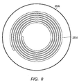
- a part of preheat flow channel 55 may be provided as spiral flow channel 253d.
- spiral flow channel 253d is formed in a spiral having the center axis of the combustion section 2 in the gravity direction as the center.
- a material for forming combustion section cylinder 22, first cylinder to eighth cylinder 21, 32, 31, 41, 51, 61, 62, and 91, and bottom section 53 composing fuel processing apparatus 1 is not particularly limited as long as molding can be performed and the material is durable at the highest temperature of the component during processing. Although various materials can be used, stainless steel may be used, for example.
- Fuel processing apparatus 1 can be manufactured by inserting cylinders made of stainless steel plates formed in cylinder shape with each other. Catalyst sections (reforming section 3, desulfurization section 5, high-temperature conversion section 6a, low-temperature conversion section 6b, ammonia decomposition section 9, selective oxidation section 10, and others) are formed between the cylinders, and combustion section 2 is formed. Reforming section 3 and desulfurization section 5 are provided in concentric circles having combustion section 2 as the center.
- vaporization flow channel 8 tilted from the upper end of reforming section 3 toward the outside is provided.
- vaporization flow channel 8 can be provided without interfering with each catalyst section.
- pipes for connecting to external apparatuses are provided at the bottom and the side surfaces of fuel processing apparatus 1. Accordingly, when assembling the apparatus by inserting the cylinders, pipes for connecting with the external apparatuses and each catalyst section do not interfere with each other. As described above, by inserting the cylinders, fuel processing apparatus 1 can be manufactured easily.
- different temperature regions are formed in concentric circles from the combustion section 2 toward outside with combustion section 2 as the center. For example, a temperature region of 600°C, a temperature region from 250°C to 300°C, a temperature region of 300°C, a temperature region of 200°C, and a temperature region of 150°C are formed.
- Reforming section 3 may be provided in the temperature region of 600°C
- desulfurization section 5 may be provided in the temperature region from 250°C to 300°C
- high-temperature conversion region 6a may be provided in the temperature region of 300°C
- low-temperature conversion section 6b and ammonia decomposition section 9 may be provided in the temperature region of 200°C
- selective oxidation section 10 may be provided in the temperature region of 150°C.
- the reaction efficiency of the converter catalyst is reduced due to variation in temperature in the converter catalyst in the conversion section.
- fuel processing apparatus 1 it is possible to effectively prevent the variation in temperature in the conversion catalyst, without increasing the amount of conversion catalyst by separating the conversion section into high-temperature conversion section 6a and low-temperature conversion section 6b.
- the variation in temperature can be effectively prevented. Since the heat generated by the catalytic reaction at high-temperature conversion section 6a is efficiently absorbed in vaporization flow channel 8, the catalytic reaction proceeds more efficiently. By improving the reaction efficiency of the catalyst, the amount of added catalyst can be reduced.
- fuel processing apparatus 1 as illustrated in FIG. 1 is prepared.
- a source gas containing methane such as LPG and city gas is supplied from a source gas supply inlet provided at cylinder 53b at bottom section 53.
- the source gas is supplied to desulfurization section 5 through preheat flow channel 55.
- preheat flow channel 55 the source gas is heated (preheated).
- the sulfur component in the source gas reacts with hydrodesulfurization catalyst stored in desulfurization section 5, and the sulfur component in the source gas is removed.
- the desulfurized source gas is supplied to vaporization flow channel 8 through a pipe (not illustrated) from an outlet for desulfurized source gas provided at bottom section main body 53a.
- the reforming water is supplied to vaporization flow channel 8, and the reforming water is heated and vaporized.
- the desulfurized source gas and the vaporized reforming water are mixed while passing through vaporization flow channel 8, generating a mixed gas.
- the mixed gas obtained is supplied to reforming section 3 filled with reformer catalyst.
- the hydrogen-containing gas is generated from the mixed gas by the reforming reaction.
- the gas reformed from the source gas to the hydrogen-containing gas is supplied from the lower end of reforming section 3 to high-temperature conversion section 6a provided along vaporization flow channel 8 illustrated in FIG. 5 through flow channel 35. Subsequently, the gas is reacted with high-temperature conversion catalyst filling high-temperature conversion section 6a. The converted gas passed through the lower end of high-temperature conversion section 6a is introduced into low-temperature conversion section 6b.
- low-temperature conversion section 6b the gas converted at a high temperature is converted again, reducing carbon monoxide in the hydrogen-containing gas.
- the gas passed through low-temperature conversion section 6b converted at low temperature is introduced into ammonia decomposition section 9 as an optional apparatus.
- the low-temperature conversion section 6b and high-temperature conversion section 6a may be continuously formed integrally.
- ammonia decomposition section 9 remaining ammonia gas is removed from the hydrogen-containing gas.
- the gas passed through ammonia decomposition section 9 is introduced into selective selection section 10 provided along vaporization flow channel 8 via flow channel 95.
- the same conversion catalyst used for low-temperature conversion section 6b is filled at a position of ammonia decomposition section 9. The purpose of this is to prevent the heat emission to outside of the apparatus.
- Selective oxidation section 10 accompanies exothermic reaction, and is provided next to vaporization flow channel 8. Accordingly, the heat generated by the catalytic reaction at selective oxidation section 10 is efficiently absorbed in vaporization flow channel 8. Accordingly, the temperature of selective oxidation section 10 is controlled to an optimum temperature, and thus the catalytic reaction proceeds efficiently.
- the hydrogen-containing gas is generated as described above.
- the fuel cell system functions by supplying the hydrogen-containing gas to a power generating stack in a fuel cell through pipes (not illustrated).
- a fuel cell system including fuel processing apparatus 1 described in Embodiment as a part can be manufactured.
- a circular truncated cone shaped space defined by tilted section 22b and lid section 24 is formed above combustion section 2.
- a tank capable of storing the reforming water in this space allows preheating the reforming water using the heat at combustion section 2.
- heat emission from fuel processing apparatus 1 can also be prevented. With this, a fuel processing apparatus having smaller influence from external environment and a catalyst having high reaction efficiency can be provided.
- the reforming water may not be sufficiently heated, not be evaporated in the vaporization flow channel, and may wet the surface of the reformer catalyst.
- the contact area of the catalyst and the gas is reduced, possibly making the catalyst less active.
- the moisture may degrade the catalyst, and may interrupt the reforming of the source gas.
- the reforming water is sufficiently heated and is evaporated easily. Accordingly, the conventional problem is solved, and the source gas is effectively reformed into hydrogen gas.
- a fuel processing apparatus capable of preheating the source gas and not easily affected by a temperature of an external environment is provided. Furthermore, according to the present invention, a fuel processing apparatus with a catalyst having high reaction efficiency is provided.
Landscapes
- Chemical & Material Sciences (AREA)
- Chemical Kinetics & Catalysis (AREA)
- Organic Chemistry (AREA)
- Engineering & Computer Science (AREA)
- Health & Medical Sciences (AREA)
- General Health & Medical Sciences (AREA)
- Combustion & Propulsion (AREA)
- Inorganic Chemistry (AREA)
- Life Sciences & Earth Sciences (AREA)
- Manufacturing & Machinery (AREA)
- Sustainable Development (AREA)
- Sustainable Energy (AREA)
- Electrochemistry (AREA)
- General Chemical & Material Sciences (AREA)
- Hydrogen, Water And Hydrids (AREA)
- Fuel Cell (AREA)
Description
- The present invention relates to a fuel processing apparatus according to claim 1 that generates hydrogen to be supplied to a fuel cell system.
- A fuel cell system such as a household cogeneration system includes a fuel processing apparatus that generates hydrogen-containing gas and a fuel cell that generates electricity using the hydrogen-containing gas generated by the fuel processing apparatus (for example, see PTL1 and 2).
- As illustrated in
FIG. 9 ,fuel processing apparatus 100 for a conventional fuel cell system includes:combustion section 102 including burner 23;desulfurization section 105 provided tosurround combustion section 102, which removes sulfur component from a source gas such as hydrogen carbonate fuel including city gas, LPG, and others;vaporization flow channel 108 in which the source gas and steam are mixed; reformingsection 103 that causes a steam reforming reaction of mixed gas at a high temperature of approximately 600°C and generates hydrogen-containing gas having hydrogen as the main component,conversion section 106 in which the concentration of carbon monoxide which is poisonous to the catalyst of a fuel cell is reduced to approximately 0.5% by the CO shift reaction, andselective oxidation section 110 that further reduces the carbon oxide concentration to approximately 10 ppm or lower by the selective oxidation reaction (for example, see PTL 3). - It is preferable that the temperature of
desulfurization section 105 is set and maintained to a high temperature of 250°C to 300°C, which is an optimum temperature for a hydrodesulfurization catalyst. In addition, it is preferable that the source gas provided todesulfurization section 105 is heated to an optimum temperature for the catalyst so as to promote the hydrodesulfurization reaction. Preheating, by the heat of the combustion section, before source fuel is supplied to the desulfurization section has been suggested (see PTL4 and PTL5). - However, as illustrated in
FIG. 9 ,desulfurization section 105 is provided outside offuel processing apparatus 100. Accordingly,desulfurization section 105 is easily affected by an external environment, making it difficult to set and maintain the temperature of thedesulfurization section 105 at an optimum temperature. When thedesulfurization section 105 is kept operating at a temperature lower than the optimum temperature, activity in hydrodesulfurization catalyst is reduced, shortening the lifetime of the hydrodesulfurization catalyst. Since the lifetime of a fuel processing apparatus is generally considered as 10 years, there has been a request for a method for reducing the influence of the temperature from external environment. - Furthermore, since a source gas at room temperature is provided to
desulfurization section 105, there is a problem that the temperature of the source gas is not raised up to a temperature sufficient for hydrodesulfurization reaction. - As a means for reducing the influence of the temperature of the external environment, providing a heat insulating section at an outer periphery of fuel processing apparatus 100 (desulfurization section 105) has been considered. For example, placing the desulfurization section in a heat insulating section provided around the combustion section has been suggested (see PTL6). However, there is a problem that providing further heat insulation material to the outer periphery of
fuel processing apparatus 100 increases the volume of the entire fuel cell system. - Alternatively, the amount of hydrodesulfurization catalyst added to
desulfurization section 105 may be increased. However, there is a problem that the increased amount of the hydrodesulfurization catalyst added increases the size of the apparatus and the cost for the fuel processing apparatus. Furthermore, PTL7 discloses, for example, a reforming apparatus in which a vaporization section is provided to surround the reforming section. Although the invention disclosed in PTL7 can reduce the amount of heat emitted from the reforming section, an effect that the influence of the temperature on the desulfurization section from the external environment is reduced is not suggested. - A fuel processing apparatus housed inside an outer package, with a plurality of reactors closely arranged in parallel has been disclosed in PTL8 as a means for keeping the temperature of the source gas at a high temperature. According to the invention disclosed in PTL8, the reformed gas can be used for preheating the source gas. However, according to the configuration, the influence of the temperature of the external environment is reduced by a granular heat insulating material filling the outer package. Accordingly, it is difficult to miniaturize the size of the apparatus. PTL8 does not suggest that the influence of the temperature on the desulfurization section from the external environment is reduced. Accordingly, a fuel processing apparatus not easily affected by the temperature of the external environment has been needed.
- Furthermore, as illustrated in
FIG. 9 , in a conventional fuel processing apparatus, there was a region A where no component is arranged around reformingsection 103 that reaches a high temperature. Since reformingsection 103 is exposed, it was necessary to provide a thick insulating material at an outer periphery of the apparatus in order to prevent the emission of heat to outside of the apparatus. The more the amount of heat insulating material, the more the volume of the apparatus becomes, despite the need for miniaturization of the apparatus. Furthermore, as illustrated inFIG. 9 ,conventional conversion section 106 is provided at one part. Sinceconversion section 106 is cooled on the inner-rim side contactingvaporization flow channel 108, exothermic reaction is mainly occurred on the upstream side of the gas. Accordingly, there is a problem that the reaction efficiency of the converter catalyst is reduced due to uneven temperature distribution in the converter catalyst. In response to the problem, a fuel processing apparatus having a catalyst with high reaction efficiency has been needed.
JP 2009-078954 A
Prior art documentWO2011/122372 A1 discloses a hydrogen production apparatus which is similar to a corresponding apparatus disclosed inJP 2010-058995 A WO2011/122372 A1 is configured to shift a reaction in low temperature shift reaction units to allow for a selective oxidation reaction to further reduce the carbon monoxide concentration. -
- PTL1
Japanese Patent Application Laid-Open No.2008-019159 - PTL2
US Patent Application Publication No. 2009-0317671 - PTL3
WO2009/150792 - PTL4
US Patent Application Publication No. 2009-0087705 - PTL5
US Patent Application Publication No. 2001-0029735 - PTL6
Japanese Patent Application Laid-Open No.2000-034103 - PTL7
Japanese Patent Application Laid-Open No.2005-104776 - PTL8
Japanese Patent Application Laid-Open No.2009-88346 - It is an object of the present invention to provide a fuel processing apparatus not easily affected by a temperature of an external environment, and capable of preheating the source gas. It is another object of the present invention to provide a fuel processing apparatus having a catalyst with high reaction efficiency.
- The above problem is solved by a fuel processing apparatus having the features set forth in claim 1.
- According to the present invention, a fuel processing apparatus not easily affected by a temperature of an external environment and capable of preheating the source gas is provided. Furthermore, according to the present invention, a fuel processing apparatus having a catalyst with high reaction efficiency is provided.
-
-
FIG. 1 is a cross-sectional view of a fuel processing apparatus according to Embodiment; -
FIG. 2 is a cross-sectional view illustrating the relationship between the first cylinder and the second cylinder as a part of the fuel processing apparatus according to Embodiment; -
FIG. 3 is a perspective view of a part of fuel processing apparatus (spiral wavy tilted part) according to Embodiment; -
FIG. 4 is a perspective view of a part of fuel processing apparatus (third cylinder) according to Embodiment; -
FIG. 5 is an enlarged cross-sectional view of a part of fuel processing apparatus according to Embodiment (vaporization flow channel and high-temperature conversion section); -
FIG. 6 is a cross-sectional view of main components of a fuel processing apparatus according to a variation of Embodiment; -
FIG. 7 is a cross-sectional view of main components of a fuel processing apparatus according to a variation of Embodiment; -
FIG. 8 is a cross-sectional view of main components of a fuel processing apparatus according to a variation of Embodiment; and -
FIG. 9 is a cross-sectional view of a conventional fuel processing apparatus. - The present invention will be described as follows based on Embodiment. However, the present invention is not limited to the following Embodiment. Components with the same function or similar function are assigned with the same or similar reference numerals, and the description for the components will be omitted. Note that the drawings are schematic. Accordingly, specific dimensions and others will be determined with reference to the following description. Needless to say, relationships of dimensions of the components and ratio may be different between the drawings.
-
FIG. 1 is a schematic cross-sectional view of a fuel processing apparatus according to Embodiment. Fuel processing apparatus 1 according to Embodiment includes:combustion section 2 having burner 23 as a heat source;desulfurization section 5 that removes sulfur component from a source gas; reformingsection 3 that generates a hydrogen-containing gas having hydrogen as main component from the desulfurized source gas; low-temperature conversion section 6b having a exothermic catalyst for reducing impurity concentration in the hydrogen-containing gas; and preheat flowchannel 55 provided at the bottom ofcombustion section 2 viaheat insulation material 4 and in communication withdesulfurization section 5, such that the source gas is preheated by the heat atcombustion section 2. - Fuel processing apparatus 1 further includes
vaporization flow channel 8.Vaporization flow channel 8 is in communication with reformingsection 3, and obliquely tilted from the upper end of reformingsection 3 toward outside, and passes through a region abovedesulfurization section 5. The source gas and steam are mixed invaporization flow channel 8. - Fuel processing apparatus 1 further includes: high-
temperature conversion section 6a provided abovedesulfurization section 5 alongvaporization flow channel 8, in communication with reformingsection 3 and low-temperature conversion section 6b, andselective oxidation section 10 in communication with low-temperature conversion section 6b provided outside of low-temperature conversion section 6b alongvaporization flow channel 8. Fuel processing apparatus 1 includesammonia decomposition section 9 including an ammonia decomposition catalyst as an exothermic catalyst downstream of low-temperature conversion section 6b, and a pipe connecting the other end ofdesulfurization section 5 and one end of vaporization flow channel 8 (not illustrated). - In fuel processing apparatus 1, reforming
section 3 anddesulfurization section 5 are provided in circle, surroundingcombustion section 2. Fromcombustion section 2 toward outside, reformingsection 3 anddesulfurization section 5 are arranged in order in concentric circles. In fuel processing apparatus 1, fromcombustion section 2 toward outside, reformingsection 3,desulfurization section 5, and low-temperature conversion section 6b are arranged in order in concentric circles. - Fuel processing apparatus 1 includes combustion section cylinder 22, first cylinder to
eighth cylinder combustion section 2. - According to fuel processing apparatus 1, the source gas is supplied to
desulfurization section 5 throughpreheat flow channel 55.Preheat flow channel 55 is provided next to the bottom ofcombustion section 2 with an insulating material in between. Accordingly, the source gas flowing throughpreheat flow channel 55 can be preheated before being supplied todesulfurization section 5. Accordingly, the desulfurization reaction atdesulfurization section 5 proceeds efficiently. - In order to preheat the source gas more efficiently, it is preferable that
preheat flow channel 55 is provided at the bottom ofcombustion section 2 and a part of side surface of combustion section 2 (a side surface near the bottom) with insulatingmaterial 4 in between. - According to fuel processing apparatus 1, reforming
section 3 anddesulfurization section 5 are provided in concentric circles fromcombustion section 2 toward outside. The reforming catalytic reaction at reformingsection 3 requires a higher reaction temperature than a reaction temperature for desulfurization catalytic reaction atdesulfurization section 5. Accordingly, in fuel processing apparatus 1, temperatures suitable for the catalytic reactions are set at reformingsection 3 anddesulfurization section 5. - Furthermore, according to fuel processing apparatus 1, low-
temperature conversion section 6b andammonia decomposition section 9 having an exothermic catalyst are provided at an outer periphery ofdesulfurization section 5. Accordingly, the hydrodesulfurization catalyst housed indesulfurization section 5 is less likely to be affected by the external environment. Accordingly, the amount of insulating material provided at an outer periphery can be reduced. Furthermore, according to fuel processing apparatus 1, by improving reaction efficiency of the desulfurization catalyst, the amount of catalyst added can be reduced and thus the apparatus can be reduced in size and weight, compared to a conventional apparatus. Furthermore, according to fuel processing apparatus 1 according to Embodiment, the activation efficiency of the reaction catalyst can be maintained at a constant value. Accordingly, it is possible to improve reliability of the apparatus. - In the following description, fuel processing apparatus 1 can be described in detail by describing each section.
-
Combustion section 2 supplies heat to the entire fuel processing apparatus 1 by operating burner 23 as a heat source of fuel processing apparatus 1.Combustion section 2 includes combustion section cylinder 22, first cylinder 21 provided at an outer periphery of combustion section cylinder 22, andlid section 24 having burner 23 provided at an upper part of combustion section cylinder 22. - Combustion section cylinder 22 includes combustion section cylinder
main body 22a and funnel-shapedtilted part 22b having a diameter widening from an upper opening toward the end of combustion section cylindermain body 22a. First cylinder 21 includes bottomed first cylindermain body 21a in whichcombustion section 2 is formed, which is provided at the outer circumference of combustion section cylindermain body 22a, and funnel-shaped (cone-shaped) first tiltedsection 21b having a diameter widening from the opening of first cylindermain body 21a toward the outermost periphery of fuel processing apparatus 1. The upper ends of first cylinder 21 and combustion section cylinder 22 are joined by vacuum welding, for example. Combustionexhaust gas path 25 is provided between first cylinder 21 and combustion section cylinder 22. -
Vaporization flow channel 8 generates a mixed gas by mixing the source gas desulfurized bydesulfurization section 5 and steam obtained by vaporizing the reforming water. Reformingsection 3 is in communication withvaporization flow channel 8, and generates hydrogen-containing gas including hydrogen as a main component from the mixed gas generated atvaporization flow channel 8. More specifically, when the source gas is a natural gas having methane as main component, steam-methane reforming reaction occurs at reformingsection 3 under the heat of approximately 600°C bycombustion section 2. Subsequently, methane and steam are reformed to gas containing hydrogen, carbon monoxide, and carbon dioxide.
CH4 + H2O → CO + 3H2 [Formula 1]
CH4 + 2H2O → CO2 + 4H2 [Formula 2]
-
Vaporization flow channel 8 includes first cylinder 21 andsecond cylinder 32 provided at an outer periphery of first cylinder 21. As illustrated inFIG. 2 ,second cylinder 32 includes second cylindermain body 32a provided at an outer periphery of first cylindermain body 21a and wavy tiltedsection 32b having a diameter widening from upper opening of second cylindermain body 32a toward the outermost circumference of fuel processing apparatus 1. Wavy tiltedsection 32b is a funnel-shaped tilted surface on which a spiral flow channel is formed. More specifically, as illustrated inFIG. 3 , a spiral flow channel is provided on wavy tiltedsection 32b. -
Upper end 32e ofsecond cylinder 32 andupper end 21c of first cylinder 21 are joined by vacuum welding, for example. Projections of first tiltedsection 21b and wavy tiltedsection 32b are welded by brazing, for example, without any gap. Accordingly,vaporization flow channel 8 is formed in a space provided between firsttilted section 21b and projecting parts of wavy tiltedsection 32b by first cylinder 21 andsecond cylinder 32. - At portions corresponding to the upper end and the lower end of reforming
section 3 betweensecond cylinder 32 and first cylinder 21,stainless steel plates stainless steel plates - As described above, reforming
section 3 in communication withvaporization flow channel 8 and capable of housing a reformer catalyst is formed in a space between first cylindermain body 21a and second cylindermain body 32a. Note that, it is preferable that the upper ends 32e and 21c are joined;stainless steel plate 32c is joined with the upper end of reformingsection 3. Subsequently, it is preferable that a catalyst is filled in reformingsection 3, andstainless steel plate 32d is joined. Other catalyst sections (desulfurization section, conversion section, oxidation section, ammonia decomposition section, and others) can be manufactured by a similar process. - By forming spiral
vaporization flow channel 8 on the tilted surface of the funnel shape, the length ofvaporization flow channel 8 can be made longer than a conventional fuel processing apparatus. By increasing the length ofvaporization flow channel 8, reforming water is more likely to be evaporated, and the reforming water will be mixed more easily with the source gas. - In addition, high-
temperature conversion section 6a andselective oxidation section 10 are provided next tovaporization flow channel 8. In high-temperature conversion section 6a, conversion reaction which is exothermic catalytic reaction occurs. The heat generated by the catalytic reaction by high-temperature conversion section 6a is effectively absorbed byvaporization flow channel 8. Accordingly, high-temperature conversion section 6a andselective oxidation section 10 are cooled, and the temperatures of the sections are controlled at optimum temperatures. With this, the catalytic reaction proceeds efficiently. - By welding the projecting parts of first tilted
section 21b and wavy tiltedsection 32b, a shortcut ofvaporization flow channel 8 by reforming water can be prevented. Furthermore, drastic change in the temperature insidevaporization flow channel 8 can be prevented. Conventionally, after a middle cylinder is inserted between an inner cylinder and an outer cylinder, the projecting part of the middle cylinder is lengthened in height by pressing the middle cylinder in the axial direction. With this process, the middle cylinder is attached closely to the outer cylinder and the inner cylinder. However, according to Embodiment, the first tiltedsection 21b and projecting parts of wavy tiltedsection 32b are closely attached. Therefore,vaporization flow channel 8 can be formed easily without a complicated process. - Tilt angle θ of first tilted
section 21b and wavy tiltedsection 32b (seeFIG. 1 ) is approximately 15 degrees to approximately 75 degrees, and is preferably 30 to 50 degrees. - Fuel processing apparatus 1 can set the aspect ratio of the entire apparatus (Y/X) in a range approximately from 0.6 to 0.9, and preferably approximately from 0.65 to 0.75 by providing first tilted
section 21b and wavy tiltedsection 32b. Considering that the aspect ratio of the conventional fuel processing apparatus is approximately in a range from 1.6 to 3.0, fuel processing apparatus 1 improves stability of setting when in use. In general, the aspect ratio that makes fuel processing apparatus 1 easy to handle is approximately 1. Accordingly, it is preferable to adjust the tilt angle θ of first tiltedsection 21b and wavy tiltedsection 32b such that the aspect ratio becomes closer to 1. Note that, the aspect ratio (Y/X) of fuel processing apparatus 1 inFIG. 1 is 235/330 = 0/71. - Various reformer catalysts can be used for the reformer catalyst provided in reforming
section 3 without any specific limit. For example, a number of ceramic porous granular material carrying reformer catalyst such as ruthenium, nickel, platinum and others can be filled in a state that allows ventilation. As the reformer catalyst, it is preferable to use platinum catalyst in terms of a viewpoint for not generating gas that affects components or catalysts of the fuel cell at the time of reforming. However, in order to suppress the cost of fuel processing apparatus 1, it is preferable to use an inexpensive nickel (Ni) catalyst than an expensive platinum catalyst. - As the reformer catalyst, using nickel (Ni) catalyst instead of platinum catalyst reduces the cost for the apparatus. However, since ammonia gas may be generated when reforming the source gas into hydrogen gas, ammonia gas may be present in the hydrogen gas, which is problematic. When ammonia gas is present in hydrogen gas, it is likely to degrade components of the fuel cell and to make the catalyst less active. Furthermore, when the fuel cell is used in a household cogeneration system, the odor of ammonia gas may be unpleasant to users. However, according to fuel processing apparatus 1 according to Embodiment, even when the nickel catalyst is used as the reformer catalyst, ammonia gas generated can be decomposed by providing
ammonia decomposition section 9. Accordingly, the problem caused by ammonia gas is solved, and the cost for the entire fuel processing apparatus 1 is reduced. - High-
temperature conversion section 6a reduces the carbon monoxide concentration in the hydrogen-containing gas generated by the reforming by reformingsection 3. More specifically, in high-temperature conversion section 6a, as illustrated in the following formula, carbon dioxide and hydrogen are generated through the reaction of carbon monoxide and steam in the hydrogen-containing gas.
CO + H2O → CO2 + H2 [Formula 3]
- High-
temperature conversion section 6a includessecond cylinder 32 and third cylinder 31 provided at the outer periphery ofsecond cylinder 32. Third cylinder 31 includes a bottomed third cylindermain body 31a provided at an outer periphery of second cylindermain body 32a and funnel-shaped second tiltedsection 31b having a diameter widening from the opening of third cylindermain body 31a toward the end. Reformingsection 3 and high-temperature conversion section 6a are in communication with each other through a flow channel formed between second cylindermain body 32a and third cylindermain body 31a and a flow channel formed between spiral wavy tiltedsection 32b and second tiltedsection 31b. -
Flow channel 31c illustrated inFIG. 4 is formed at a part of second tiltedsection 31b in third cylinder 31. High-temperature conversion section 6a is provided inflow channel 31c, and is adjacent tovaporization flow channel 8 through second tiltedsection 31b (FIG. 5 ). As illustrated inFIG. 5 , the gas passed throughflow channel 31c passes throughflow channel 31d and high-temperature conversion section 6a, and turns back to low-temperature conversion section 6b. - As a high-temperature converter catalyst, a copper-based catalyst may be used.
-
Desulfurization section 5 removes sulfur component from hydrocarbon source gas such as city gas supplied (hydrocarbon raw fuel). -
Desulfurization section 5 is formed between bottomedfourth cylinder 41 andfifth cylinder 51 provided at an outer periphery offourth cylinder 41, and a desulfurization catalyst is provided. Insulatingmaterial 4 is provided betweenfourth cylinder 41 and third cylindermain body 31a. At portions corresponding to the upper end and the lower end ofdesulfurization section 5, stainless steel plates are joined by welding, for example. A through hole is provided on the main surface of the stainless steel plate, allowing gas to pass through. - Bottom section 53 includes tabular disc-shaped bottom section
main body 53a and bottomedcylinder 53b provided to surround outer circumference of a bottom offourth cylinder 41 as a cavity at the center part of the bottom sectionmain body 53a.Preheat flow channel 55 in communication withdesulfurization section 5 is formed betweenfourth cylinder 41 andcylinder 53b. - As a (hydro) desulfurization catalyst, various desulfurization catalyst can be used without any specific limit. As a desulfurization catalyst, a copper-based catalyst may be used, for example.
- Low-
temperature conversion section 6b is formed betweensixth cylinder 61 andseventh cylinder 62.Sixth cylinder 61 is provided at an outer periphery offifth cylinder 51, and the upper end ofsixth cylinder 61 is in contact with second tiltedsection 31b.Seventh cylinder 62 is provided at an outer periphery ofsixth cylinder 61, and the upper end ofseventh cylinder 62 is in contact with second tiltedsection 31b. At portions corresponding to the upper end and the lower end of low-temperature conversion section 6b, stainless steel plates are joined by welding, for example. A through hole is provided on the main surface of the stainless steel plate, allowing gas to pass through. -
Ammonia decomposition section 9 is formed betweensixth cylinder 61 andseventh cylinder 62, and is provided on a downstream side of low-temperature conversion section 6b with regard to the direction of the gas flow. - Low-
temperature conversion section 6b includes a low-temperature conversion catalyst as the exothermic catalyst.Ammonia decomposition section 9 includes an ammonia decomposing catalyst as the exothermic catalyst. As the low-temperature conversion catalyst and the ammonia decomposing catalyst, a copper-based catalyst may be used. -
Selective oxidation section 10 removes carbon monoxide remaining in the gas converted by high-temperature conversion section 6a and low-temperature conversion section 6b. More specifically, inselective oxidation section 10, carbon monoxide remaining in the gas converted at a reaction temperature of approximately 100°C to 200°C by the catalytic action of ruthenium or others is oxidized by oxygen in added air. -
Selective oxidation section 10 is provided betweeneighth cylinder 91 andseventh cylinder 62.Eighth cylinder 91 is provided at an outer periphery ofseventh cylinder 62, and is in communication withammonia decomposition section 9 throughflow channel 95.Selective oxidation section 10 is provided alongvaporization flow channel 8 and outside of low-temperature conversion section 6b. -
Preheat flow channel 55 is formed betweenfirst cylinder 41 and bottomedcylinder 53b. It is preferable that an inlet for the source gas is provided at a part of bottomedcylinder 53b corresponding to the center axis ofcombustion section 2 in the gravity direction. Furthermore, preheat flowchannel 55 is formed radially with the center axis of the combustion section in the gravity direction as the center. Accordingly, the source gas supplied from the source gas inlet to preheatflow channel 55 is preheated by the heat fromcombustion section 2. Subsequently, the preheated (for example, heated up to approximately 250°C) source gas is supplied todesulfurization section 5. Accordingly, the desulfurization reaction atdesulfurization section 5 proceeds efficiently. - The shape of
preheat flow channel 55 is not limited to radial shape, as long as the supplied source gas is preheated. For example, as illustrated inFIG. 6 , a reversed circular truncated cone-shapedpreheat cavity 153d may be provided at a part ofpreheat flow channel 55. It is preferable that the center axis ofcombustion section 2 in the gravity direction passes through the center of the bottom surface and the upper surface of the reversed circular truncated cone definingpreheat cavity 153d. Stated differently, circular truncated cone-shapedpreheat cavity 153d having the center axis of thecombustion section 2 in the gravity direction as the center, and a diameter widening from the center toward the outside may be provided at a part ofpreheat flow channel 55.Preheat cavity 153d is in communication withpreheat flow channel 55 having a diameter smaller than preheat cavity 153 at the large-diameter end of the reversed truncated cone inpreheat cavity 153d. - With the configuration described above, the source gas supplied from the source gas inlet flows at a low speed in
preheat cavity 153d. Accordingly, the source gas is preheated easily, and the temperature is set at a constant temperature easily. Subsequently, the preheated source gas flows at high flow speed in the small-diameterpreheat flow channel 55, and is supplied todesulfurization section 5. With this, the source gas is preheated reliably, reducing variation in the temperature of the source gas. - In the fuel processing apparatus according to Embodiment, the source gas supplied from the supply inlet is preheated at
preheat cavity 153d, and then provided todesulfurization section 5. Accordingly, even when the amount of supply of the source gas is changed due to a sudden increase in the supply amount of the source gas or temporary discontinuation of the supply, it is easy to supply the source gas preheated to a desired temperature todesulfurization section 5. - In addition, forming
preheat cavity 153d allows effective prevention of heat emission from fuel processing apparatus 1. - Furthermore, as illustrated in
FIG. 7 , a part ofpreheat flow channel 55 may be provided asspiral flow channel 253d. As illustrated inFIG. 8 ,spiral flow channel 253d is formed in a spiral having the center axis of thecombustion section 2 in the gravity direction as the center. By formingspiral flow channel 253d, the source gas is preheated while flowing in the circumferential direction. Accordingly, the source gas is preheated even more reliably. In addition, the variation in the temperature of the source gas can be reduced. Furthermore, the source gas can be preheated without increasing the size of fuel processing apparatus 1. - A material for forming combustion section cylinder 22, first cylinder to
eighth cylinder - Fuel processing apparatus 1 can be manufactured by inserting cylinders made of stainless steel plates formed in cylinder shape with each other. Catalyst sections (reforming
section 3,desulfurization section 5, high-temperature conversion section 6a, low-temperature conversion section 6b,ammonia decomposition section 9,selective oxidation section 10, and others) are formed between the cylinders, andcombustion section 2 is formed. Reformingsection 3 anddesulfurization section 5 are provided in concentric circles havingcombustion section 2 as the center. - Furthermore, above
desulfurization section 5 and low-temperature conversion section 6b,vaporization flow channel 8 tilted from the upper end of reformingsection 3 toward the outside is provided. With this,vaporization flow channel 8 can be provided without interfering with each catalyst section. - Furthermore, pipes for connecting to external apparatuses are provided at the bottom and the side surfaces of fuel processing apparatus 1. Accordingly, when assembling the apparatus by inserting the cylinders, pipes for connecting with the external apparatuses and each catalyst section do not interfere with each other. As described above, by inserting the cylinders, fuel processing apparatus 1 can be manufactured easily.
- According to fuel processing apparatus 1, when the apparatus is in operation, different temperature regions are formed in concentric circles from the
combustion section 2 toward outside withcombustion section 2 as the center. For example, a temperature region of 600°C, a temperature region from 250°C to 300°C, a temperature region of 300°C, a temperature region of 200°C, and a temperature region of 150°C are formed. Reformingsection 3 may be provided in the temperature region of 600°C,desulfurization section 5 may be provided in the temperature region from 250°C to 300°C, high-temperature conversion region 6a may be provided in the temperature region of 300°C, low-temperature conversion section 6b andammonia decomposition section 9 may be provided in the temperature region of 200°C, andselective oxidation section 10 may be provided in the temperature region of 150°C. With this, each catalyst section is provided in a preferable temperature region for the catalyst in each catalyst section, improving the reaction efficiency of the catalyst. - In the conventional fuel processing apparatus, it is necessary to provide a thick insulating material covering the reforming section at an outer periphery of the apparatus in order to prevent the emission of heat from reforming section to outside of the apparatus. In contrast, according to fuel processing apparatus 1,
ammonia decomposition section 9 andselective oxidation section 10 provided outside of the apparatus also have the insulation effect. Stated differently, according to fuel processing apparatus 1, it is possible to prevent heat dissipation and to reduce the thickness of the heat insulating material provided at an outer periphery of the apparatus compared to the conventional apparatus, thereby achieving miniaturization of the apparatus. - In the conventional fuel processing apparatus, the reaction efficiency of the converter catalyst is reduced due to variation in temperature in the converter catalyst in the conversion section. However, according to fuel processing apparatus 1, it is possible to effectively prevent the variation in temperature in the conversion catalyst, without increasing the amount of conversion catalyst by separating the conversion section into high-
temperature conversion section 6a and low-temperature conversion section 6b. - In particular, by providing a high-temperature conversion catalyst in high-
temperature conversion section 6a provided alongvaporization flow channel 8, and providing a low-temperature conversion catalyst in low-temperature conversion section 6b, the variation in temperature can be effectively prevented. Since the heat generated by the catalytic reaction at high-temperature conversion section 6a is efficiently absorbed invaporization flow channel 8, the catalytic reaction proceeds more efficiently. By improving the reaction efficiency of the catalyst, the amount of added catalyst can be reduced. - Next, the process for processing the source gas into hydrogen-containing gas (gas flow) will be described by describing the fuel processing method.
- First, fuel processing apparatus 1 as illustrated in
FIG. 1 is prepared. Next, a source gas containing methane such as LPG and city gas is supplied from a source gas supply inlet provided atcylinder 53b at bottom section 53. The source gas is supplied todesulfurization section 5 throughpreheat flow channel 55. Inpreheat flow channel 55, the source gas is heated (preheated). The sulfur component in the source gas reacts with hydrodesulfurization catalyst stored indesulfurization section 5, and the sulfur component in the source gas is removed. - The desulfurized source gas is supplied to
vaporization flow channel 8 through a pipe (not illustrated) from an outlet for desulfurized source gas provided at bottom sectionmain body 53a. At the same time, the reforming water is supplied tovaporization flow channel 8, and the reforming water is heated and vaporized. Subsequently, the desulfurized source gas and the vaporized reforming water are mixed while passing throughvaporization flow channel 8, generating a mixed gas. The mixed gas obtained is supplied to reformingsection 3 filled with reformer catalyst. The hydrogen-containing gas is generated from the mixed gas by the reforming reaction. - The gas reformed from the source gas to the hydrogen-containing gas is supplied from the lower end of reforming
section 3 to high-temperature conversion section 6a provided alongvaporization flow channel 8 illustrated inFIG. 5 throughflow channel 35. Subsequently, the gas is reacted with high-temperature conversion catalyst filling high-temperature conversion section 6a. The converted gas passed through the lower end of high-temperature conversion section 6a is introduced into low-temperature conversion section 6b. - In low-
temperature conversion section 6b, the gas converted at a high temperature is converted again, reducing carbon monoxide in the hydrogen-containing gas. The gas passed through low-temperature conversion section 6b converted at low temperature is introduced intoammonia decomposition section 9 as an optional apparatus. Note that, the low-temperature conversion section 6b and high-temperature conversion section 6a may be continuously formed integrally. - At
ammonia decomposition section 9, remaining ammonia gas is removed from the hydrogen-containing gas. The gas passed throughammonia decomposition section 9 is introduced intoselective selection section 10 provided alongvaporization flow channel 8 viaflow channel 95. Note that, when it is not necessary to remove ammonia from the hydrogen-containing gas, it is preferable that the same conversion catalyst used for low-temperature conversion section 6b is filled at a position ofammonia decomposition section 9. The purpose of this is to prevent the heat emission to outside of the apparatus. - Carbon monoxide gas remaining in the gas is removed further at
selective oxidation section 10.Selective oxidation section 10 accompanies exothermic reaction, and is provided next tovaporization flow channel 8. Accordingly, the heat generated by the catalytic reaction atselective oxidation section 10 is efficiently absorbed invaporization flow channel 8. Accordingly, the temperature ofselective oxidation section 10 is controlled to an optimum temperature, and thus the catalytic reaction proceeds efficiently. - The hydrogen-containing gas is generated as described above. The fuel cell system functions by supplying the hydrogen-containing gas to a power generating stack in a fuel cell through pipes (not illustrated).
- The present invention has been described above with reference to Embodiment. However, it should not be understood that the description and drawings included as a part of the disclosure has a limiting effect on the present invention. The disclosure articulates various alternative embodiments, examples, and operation technologies for a person skilled in the art.
- For example, a fuel cell system including fuel processing apparatus 1 described in Embodiment as a part can be manufactured.
- In fuel processing apparatus 1, a circular truncated cone shaped space defined by tilted
section 22b andlid section 24 is formed abovecombustion section 2. By providing a tank capable of storing the reforming water in this space allows preheating the reforming water using the heat atcombustion section 2. In addition, since heated reforming water is provided abovecombustion section 2, heat emission from fuel processing apparatus 1 can also be prevented. With this, a fuel processing apparatus having smaller influence from external environment and a catalyst having high reaction efficiency can be provided. - Conventionally, in
vaporization flow channel 8, the reforming water may not be sufficiently heated, not be evaporated in the vaporization flow channel, and may wet the surface of the reformer catalyst. When the surface of the reformer catalyst is wet, the contact area of the catalyst and the gas is reduced, possibly making the catalyst less active. Furthermore, when the catalyst is wet, the moisture may degrade the catalyst, and may interrupt the reforming of the source gas. However, by preheating the reforming water, the reforming water is sufficiently heated and is evaporated easily. Accordingly, the conventional problem is solved, and the source gas is effectively reformed into hydrogen gas. - Needless to say, the present invention includes various embodiments that have not been described herein. Accordingly, the technical scope of the present invention is determined merely by the features of the invention according to the appended claims reasonably arrived based on the description above.
- According to the present invention, a fuel processing apparatus capable of preheating the source gas and not easily affected by a temperature of an external environment is provided. Furthermore, according to the present invention, a fuel processing apparatus with a catalyst having high reaction efficiency is provided.
-
- 1 Fuel processing apparatus
- 2 Combustion section
- 3 Reforming section
- 5 Hydrodesulfurization section
- 6a High-temperature conversion section
- 6b Low-temperature conversion section
- 8 Vaporization flow channel
- 9 Ammonia decomposition section
- 10 Selective oxidation section
- 23 Burner
- 22 Combustion section cylinder
- 21 First cylinder
- 32 Second cylinder
- 31 Third cylinder
- 41 Fourth cylinder
- 51 Fifth cylinder
- 61 Sixth cylinder
- 62 Seventh cylinder
- 91 Eighth cylinder
- 53 Bottom
- 55 Preheat flow path
- 153d Preheat cavity
- 253d Spiral flow channel
Claims (7)
- A fuel processing apparatus comprising:a combustion section having a heat source;a desulfurization section that removes sulfur component from a source gas;a reforming section that generates hydrogen-containing gas having hydrogen as a main component from the source gas desulfurized; anda low-temperature conversion section having a heat-generating catalyst that reduces an impurity concentration in the hydrogen-containing gas,characterized by the following features:the reforming section, the desulfurization section, and the low-temperature conversion section are provided surrounding the combustion section, and the reforming section, the desulfurization section, and the low-temperature conversion section are formed in order in concentric circles from the combustion section toward outside, andthe fuel processing apparatus further comprises a preheat flow channel provided at a bottom of the combustion section with an insulating material interposed in between and in communication with the desulfurization section, such that the source gas is preheated using heat from the combustion section.
- The fuel processing apparatus according to claim 1, further comprising a preheat cavity at a part of the preheat flow channel, the preheat cavity having a reversed truncated cone shape with a center axis of the combustion section in a gravity direction as a center and a diameter widening from the center toward outside.
- The fuel processing apparatus according to claim 2, wherein an end of the preheat cavity on a large-diameter radial direction side is in communication with the preheat flow channel having a diameter smaller than a diameter of the preheat cavity.
- The fuel processing apparatus according to claim 1, wherein the preheat flow channel is formed radially from a center axis of the combustion section in a gravity direction as a center.
- The fuel processing apparatus according to claim 1, wherein the preheat flow channel is formed in a spiral from a center axis of the combustion section in a gravity direction as a center.
- The fuel processing apparatus according to claim 1, wherein the preheat flow channel includes a source gas inlet at a part corresponding to a center axis of the combustion section in a gravity direction.
- The fuel processing apparatus according to claim 1, wherein the preheat flow channel is provided to cover the bottom of the combustion section and a part of a side of the combustion section.
Applications Claiming Priority (2)
| Application Number | Priority Date | Filing Date | Title |
|---|---|---|---|
| JP2012141991 | 2012-06-25 | ||
| PCT/JP2013/003944 WO2014002472A1 (en) | 2012-06-25 | 2013-06-24 | Fuel processing device |
Publications (3)
| Publication Number | Publication Date |
|---|---|
| EP2735541A1 EP2735541A1 (en) | 2014-05-28 |
| EP2735541A4 EP2735541A4 (en) | 2015-01-14 |
| EP2735541B1 true EP2735541B1 (en) | 2016-03-09 |
Family
ID=49782664
Family Applications (1)
| Application Number | Title | Priority Date | Filing Date |
|---|---|---|---|
| EP13810310.6A Active EP2735541B1 (en) | 2012-06-25 | 2013-06-24 | Fuel processing device |
Country Status (4)
| Country | Link |
|---|---|
| US (1) | US9144781B2 (en) |
| EP (1) | EP2735541B1 (en) |
| JP (1) | JP5427326B1 (en) |
| WO (1) | WO2014002472A1 (en) |
Families Citing this family (5)
| Publication number | Priority date | Publication date | Assignee | Title |
|---|---|---|---|---|
| JP5483787B1 (en) * | 2012-06-25 | 2014-05-07 | パナソニック株式会社 | Fuel processor |
| JP6205581B2 (en) * | 2014-02-17 | 2017-10-04 | パナソニックIpマネジメント株式会社 | Hydrogen generator and fuel cell system using the same |
| EP2919310B1 (en) * | 2014-03-14 | 2018-07-11 | Panasonic Corporation | Fuel cell system |
| JP6530915B2 (en) * | 2015-01-09 | 2019-06-12 | 本田技研工業株式会社 | Fuel cell module |
| CN115504434B (en) * | 2022-11-09 | 2023-08-01 | 常州创氢能源科技有限公司 | Self-heating reforming hydrogen production reactor |
Family Cites Families (15)
| Publication number | Priority date | Publication date | Assignee | Title |
|---|---|---|---|---|
| JP2000034103A (en) | 1998-07-21 | 2000-02-02 | Matsushita Electric Works Ltd | Fuel reformer |
| JP3625770B2 (en) | 1999-04-20 | 2005-03-02 | 東京瓦斯株式会社 | Single tube cylindrical reformer and its operating method |
| JP4161612B2 (en) | 2002-05-15 | 2008-10-08 | 株式会社Ihi | Starting method of fuel reformer |
| JP2004185942A (en) * | 2002-12-02 | 2004-07-02 | Sanyo Electric Co Ltd | Hydrogen generating device for fuel cell |
| JP4316975B2 (en) | 2003-09-30 | 2009-08-19 | アイシン精機株式会社 | Reformer |
| CN101233075B (en) * | 2005-09-30 | 2012-10-24 | 松下电器产业株式会社 | Hydrogen generator and fuel cell system |
| WO2007145218A1 (en) | 2006-06-12 | 2007-12-21 | Panasonic Corporation | Hydrogen generation device and fuel cell system equipped with it |
| JP5138986B2 (en) | 2006-06-12 | 2013-02-06 | 富士電機株式会社 | Hydrogen generator and fuel cell system including the same |
| JP2009078954A (en) * | 2007-09-27 | 2009-04-16 | Fuji Electric Holdings Co Ltd | Reformer |
| US8178062B2 (en) | 2007-09-27 | 2012-05-15 | Sanyo Electric Co., Ltd. | Reforming apparatus for fuel cell |
| JP2009088346A (en) | 2007-10-01 | 2009-04-23 | Hitachi Kokusai Electric Inc | Substrate processing equipment |
| CN101679033B (en) | 2008-06-13 | 2013-02-27 | 松下电器产业株式会社 | Fuel processor |
| JP5191840B2 (en) * | 2008-09-01 | 2013-05-08 | 東京瓦斯株式会社 | Cylindrical steam reformer with integrated hydrodesulfurizer |
| JP5610812B2 (en) | 2010-03-30 | 2014-10-22 | Jx日鉱日石エネルギー株式会社 | Hydrogen production apparatus and fuel cell system |
| JP5409486B2 (en) | 2010-03-30 | 2014-02-05 | Jx日鉱日石エネルギー株式会社 | Hydrogen production apparatus and fuel cell system |
-
2013
- 2013-06-24 JP JP2013546120A patent/JP5427326B1/en not_active Expired - Fee Related
- 2013-06-24 EP EP13810310.6A patent/EP2735541B1/en active Active
- 2013-06-24 WO PCT/JP2013/003944 patent/WO2014002472A1/en not_active Ceased
- 2013-06-24 US US14/404,624 patent/US9144781B2/en not_active Expired - Fee Related
Also Published As
| Publication number | Publication date |
|---|---|
| JP5427326B1 (en) | 2014-02-26 |
| EP2735541A1 (en) | 2014-05-28 |
| WO2014002472A1 (en) | 2014-01-03 |
| US9144781B2 (en) | 2015-09-29 |
| EP2735541A4 (en) | 2015-01-14 |
| JPWO2014002472A1 (en) | 2016-05-30 |
| US20150118129A1 (en) | 2015-04-30 |
Similar Documents
| Publication | Publication Date | Title |
|---|---|---|
| US9144781B2 (en) | Fuel processing device | |
| JP2009078954A (en) | Reformer | |
| EP2716598B1 (en) | Hydrogen generator and fuel cell system | |
| JP2010058995A (en) | Hydrogenation desulfurizer-integrated cylindrical steam reformer | |
| JP4870491B2 (en) | Fuel reformer | |
| JP2009096705A (en) | Fuel cell reformer | |
| EP2835345B1 (en) | Fuel treatment device | |
| US20130065144A1 (en) | Hydrogen production apparatus and fuel cell system | |
| JP5161621B2 (en) | Fuel cell reformer | |
| JP7756303B2 (en) | Hydrogen generator | |
| JP2008137832A (en) | Hydrogen generator and fuel cell system | |
| JP4764651B2 (en) | Hydrogen production apparatus and fuel cell system | |
| JP2007331985A (en) | Hydrogen generator and fuel cell power generator using the same | |
| JP2011098840A (en) | Hydrogen production apparatus for fuel cell | |
| JP4431455B2 (en) | Reformer | |
| JP2017077992A (en) | Hydrogen generator and fuel cell system using the same | |
| JP2005247617A (en) | Shift reactor | |
| JP2015010012A (en) | Fuel treatment device | |
| JP6197561B2 (en) | Hydrogen generator | |
| JP6205581B2 (en) | Hydrogen generator and fuel cell system using the same | |
| JP2009084079A (en) | Fuel cell reformer | |
| JP2012176897A (en) | Hydrogenation desulfurizer-integrated cylindrical steam reformer | |
| JP2014005171A (en) | Fuel treatment device and manufacturing method therefor | |
| JP2016222497A (en) | Hydrogen generator and fuel cell system using the same | |
| JP2008290912A (en) | Fuel cell reformer |
Legal Events
| Date | Code | Title | Description |
|---|---|---|---|
| PUAI | Public reference made under article 153(3) epc to a published international application that has entered the european phase |
Free format text: ORIGINAL CODE: 0009012 |
|
| 17P | Request for examination filed |
Effective date: 20140221 |
|
| AK | Designated contracting states |
Kind code of ref document: A1 Designated state(s): AL AT BE BG CH CY CZ DE DK EE ES FI FR GB GR HR HU IE IS IT LI LT LU LV MC MK MT NL NO PL PT RO RS SE SI SK SM TR |
|
| RAP1 | Party data changed (applicant data changed or rights of an application transferred) |
Owner name: PANASONIC INTELLECTUAL PROPERTY MANAGEMENT CO., LT |
|
| A4 | Supplementary search report drawn up and despatched |
Effective date: 20141215 |
|
| RIC1 | Information provided on ipc code assigned before grant |
Ipc: C01B 3/38 20060101AFI20141209BHEP Ipc: H01M 8/06 20060101ALI20141209BHEP Ipc: B01J 8/04 20060101ALN20141209BHEP Ipc: C01B 3/48 20060101ALI20141209BHEP |
|
| RIC1 | Information provided on ipc code assigned before grant |
Ipc: C01B 3/48 20060101ALI20150820BHEP Ipc: B01J 8/04 20060101ALN20150820BHEP Ipc: C01B 3/38 20060101AFI20150820BHEP Ipc: B01J 19/24 20060101ALN20150820BHEP Ipc: H01M 8/06 20060101ALI20150820BHEP |
|
| GRAP | Despatch of communication of intention to grant a patent |
Free format text: ORIGINAL CODE: EPIDOSNIGR1 |
|
| DAX | Request for extension of the european patent (deleted) | ||
| INTG | Intention to grant announced |
Effective date: 20150930 |
|
| GRAS | Grant fee paid |
Free format text: ORIGINAL CODE: EPIDOSNIGR3 |
|
| GRAA | (expected) grant |
Free format text: ORIGINAL CODE: 0009210 |
|
| AK | Designated contracting states |
Kind code of ref document: B1 Designated state(s): AL AT BE BG CH CY CZ DE DK EE ES FI FR GB GR HR HU IE IS IT LI LT LU LV MC MK MT NL NO PL PT RO RS SE SI SK SM TR |
|
| REG | Reference to a national code |
Ref country code: GB Ref legal event code: FG4D |
|
| REG | Reference to a national code |
Ref country code: AT Ref legal event code: REF Ref document number: 779332 Country of ref document: AT Kind code of ref document: T Effective date: 20160315 Ref country code: CH Ref legal event code: EP |
|
| REG | Reference to a national code |
Ref country code: IE Ref legal event code: FG4D |
|
| REG | Reference to a national code |
Ref country code: DE Ref legal event code: R096 Ref document number: 602013005440 Country of ref document: DE |
|
| REG | Reference to a national code |
Ref country code: FR Ref legal event code: PLFP Year of fee payment: 4 |
|
| REG | Reference to a national code |
Ref country code: LT Ref legal event code: MG4D |
|
| REG | Reference to a national code |
Ref country code: NL Ref legal event code: MP Effective date: 20160309 |
|
| PG25 | Lapsed in a contracting state [announced via postgrant information from national office to epo] |
Ref country code: ES Free format text: LAPSE BECAUSE OF FAILURE TO SUBMIT A TRANSLATION OF THE DESCRIPTION OR TO PAY THE FEE WITHIN THE PRESCRIBED TIME-LIMIT Effective date: 20160309 Ref country code: NO Free format text: LAPSE BECAUSE OF FAILURE TO SUBMIT A TRANSLATION OF THE DESCRIPTION OR TO PAY THE FEE WITHIN THE PRESCRIBED TIME-LIMIT Effective date: 20160609 Ref country code: FI Free format text: LAPSE BECAUSE OF FAILURE TO SUBMIT A TRANSLATION OF THE DESCRIPTION OR TO PAY THE FEE WITHIN THE PRESCRIBED TIME-LIMIT Effective date: 20160309 Ref country code: GR Free format text: LAPSE BECAUSE OF FAILURE TO SUBMIT A TRANSLATION OF THE DESCRIPTION OR TO PAY THE FEE WITHIN THE PRESCRIBED TIME-LIMIT Effective date: 20160610 Ref country code: HR Free format text: LAPSE BECAUSE OF FAILURE TO SUBMIT A TRANSLATION OF THE DESCRIPTION OR TO PAY THE FEE WITHIN THE PRESCRIBED TIME-LIMIT Effective date: 20160309 |
|
| REG | Reference to a national code |
Ref country code: AT Ref legal event code: MK05 Ref document number: 779332 Country of ref document: AT Kind code of ref document: T Effective date: 20160309 |
|
| PG25 | Lapsed in a contracting state [announced via postgrant information from national office to epo] |
Ref country code: LV Free format text: LAPSE BECAUSE OF FAILURE TO SUBMIT A TRANSLATION OF THE DESCRIPTION OR TO PAY THE FEE WITHIN THE PRESCRIBED TIME-LIMIT Effective date: 20160309 Ref country code: RS Free format text: LAPSE BECAUSE OF FAILURE TO SUBMIT A TRANSLATION OF THE DESCRIPTION OR TO PAY THE FEE WITHIN THE PRESCRIBED TIME-LIMIT Effective date: 20160309 Ref country code: SE Free format text: LAPSE BECAUSE OF FAILURE TO SUBMIT A TRANSLATION OF THE DESCRIPTION OR TO PAY THE FEE WITHIN THE PRESCRIBED TIME-LIMIT Effective date: 20160309 Ref country code: PL Free format text: LAPSE BECAUSE OF FAILURE TO SUBMIT A TRANSLATION OF THE DESCRIPTION OR TO PAY THE FEE WITHIN THE PRESCRIBED TIME-LIMIT Effective date: 20160309 Ref country code: LT Free format text: LAPSE BECAUSE OF FAILURE TO SUBMIT A TRANSLATION OF THE DESCRIPTION OR TO PAY THE FEE WITHIN THE PRESCRIBED TIME-LIMIT Effective date: 20160309 Ref country code: NL Free format text: LAPSE BECAUSE OF FAILURE TO SUBMIT A TRANSLATION OF THE DESCRIPTION OR TO PAY THE FEE WITHIN THE PRESCRIBED TIME-LIMIT Effective date: 20160309 |
|
| PG25 | Lapsed in a contracting state [announced via postgrant information from national office to epo] |
Ref country code: IS Free format text: LAPSE BECAUSE OF FAILURE TO SUBMIT A TRANSLATION OF THE DESCRIPTION OR TO PAY THE FEE WITHIN THE PRESCRIBED TIME-LIMIT Effective date: 20160709 Ref country code: EE Free format text: LAPSE BECAUSE OF FAILURE TO SUBMIT A TRANSLATION OF THE DESCRIPTION OR TO PAY THE FEE WITHIN THE PRESCRIBED TIME-LIMIT Effective date: 20160309 |
|
| PG25 | Lapsed in a contracting state [announced via postgrant information from national office to epo] |
Ref country code: PT Free format text: LAPSE BECAUSE OF FAILURE TO SUBMIT A TRANSLATION OF THE DESCRIPTION OR TO PAY THE FEE WITHIN THE PRESCRIBED TIME-LIMIT Effective date: 20160711 Ref country code: AT Free format text: LAPSE BECAUSE OF FAILURE TO SUBMIT A TRANSLATION OF THE DESCRIPTION OR TO PAY THE FEE WITHIN THE PRESCRIBED TIME-LIMIT Effective date: 20160309 Ref country code: SM Free format text: LAPSE BECAUSE OF FAILURE TO SUBMIT A TRANSLATION OF THE DESCRIPTION OR TO PAY THE FEE WITHIN THE PRESCRIBED TIME-LIMIT Effective date: 20160309 Ref country code: CZ Free format text: LAPSE BECAUSE OF FAILURE TO SUBMIT A TRANSLATION OF THE DESCRIPTION OR TO PAY THE FEE WITHIN THE PRESCRIBED TIME-LIMIT Effective date: 20160309 Ref country code: SK Free format text: LAPSE BECAUSE OF FAILURE TO SUBMIT A TRANSLATION OF THE DESCRIPTION OR TO PAY THE FEE WITHIN THE PRESCRIBED TIME-LIMIT Effective date: 20160309 Ref country code: RO Free format text: LAPSE BECAUSE OF FAILURE TO SUBMIT A TRANSLATION OF THE DESCRIPTION OR TO PAY THE FEE WITHIN THE PRESCRIBED TIME-LIMIT Effective date: 20160309 |
|
| REG | Reference to a national code |
Ref country code: DE Ref legal event code: R097 Ref document number: 602013005440 Country of ref document: DE |
|
| PG25 | Lapsed in a contracting state [announced via postgrant information from national office to epo] |
Ref country code: BE Free format text: LAPSE BECAUSE OF FAILURE TO SUBMIT A TRANSLATION OF THE DESCRIPTION OR TO PAY THE FEE WITHIN THE PRESCRIBED TIME-LIMIT Effective date: 20160309 Ref country code: IT Free format text: LAPSE BECAUSE OF FAILURE TO SUBMIT A TRANSLATION OF THE DESCRIPTION OR TO PAY THE FEE WITHIN THE PRESCRIBED TIME-LIMIT Effective date: 20160309 |
|
| PLBE | No opposition filed within time limit |
Free format text: ORIGINAL CODE: 0009261 |
|
| STAA | Information on the status of an ep patent application or granted ep patent |
Free format text: STATUS: NO OPPOSITION FILED WITHIN TIME LIMIT |
|
| PG25 | Lapsed in a contracting state [announced via postgrant information from national office to epo] |
Ref country code: MC Free format text: LAPSE BECAUSE OF FAILURE TO SUBMIT A TRANSLATION OF THE DESCRIPTION OR TO PAY THE FEE WITHIN THE PRESCRIBED TIME-LIMIT Effective date: 20160309 Ref country code: DK Free format text: LAPSE BECAUSE OF FAILURE TO SUBMIT A TRANSLATION OF THE DESCRIPTION OR TO PAY THE FEE WITHIN THE PRESCRIBED TIME-LIMIT Effective date: 20160309 |
|
| REG | Reference to a national code |
Ref country code: CH Ref legal event code: PL |
|
| 26N | No opposition filed |
Effective date: 20161212 |
|
| PG25 | Lapsed in a contracting state [announced via postgrant information from national office to epo] |
Ref country code: BG Free format text: LAPSE BECAUSE OF FAILURE TO SUBMIT A TRANSLATION OF THE DESCRIPTION OR TO PAY THE FEE WITHIN THE PRESCRIBED TIME-LIMIT Effective date: 20160609 |
|
| REG | Reference to a national code |
Ref country code: IE Ref legal event code: MM4A |
|
| PG25 | Lapsed in a contracting state [announced via postgrant information from national office to epo] |
Ref country code: CH Free format text: LAPSE BECAUSE OF NON-PAYMENT OF DUE FEES Effective date: 20160630 Ref country code: LI Free format text: LAPSE BECAUSE OF NON-PAYMENT OF DUE FEES Effective date: 20160630 |
|
| PG25 | Lapsed in a contracting state [announced via postgrant information from national office to epo] |
Ref country code: IE Free format text: LAPSE BECAUSE OF NON-PAYMENT OF DUE FEES Effective date: 20160624 Ref country code: SI Free format text: LAPSE BECAUSE OF FAILURE TO SUBMIT A TRANSLATION OF THE DESCRIPTION OR TO PAY THE FEE WITHIN THE PRESCRIBED TIME-LIMIT Effective date: 20160309 |
|
| REG | Reference to a national code |
Ref country code: FR Ref legal event code: PLFP Year of fee payment: 5 |
|
| PG25 | Lapsed in a contracting state [announced via postgrant information from national office to epo] |
Ref country code: HU Free format text: LAPSE BECAUSE OF FAILURE TO SUBMIT A TRANSLATION OF THE DESCRIPTION OR TO PAY THE FEE WITHIN THE PRESCRIBED TIME-LIMIT; INVALID AB INITIO Effective date: 20130624 |
|
| REG | Reference to a national code |
Ref country code: FR Ref legal event code: PLFP Year of fee payment: 6 |
|
| PG25 | Lapsed in a contracting state [announced via postgrant information from national office to epo] |
Ref country code: LU Free format text: LAPSE BECAUSE OF NON-PAYMENT OF DUE FEES Effective date: 20160624 Ref country code: MT Free format text: LAPSE BECAUSE OF NON-PAYMENT OF DUE FEES Effective date: 20160630 Ref country code: CY Free format text: LAPSE BECAUSE OF FAILURE TO SUBMIT A TRANSLATION OF THE DESCRIPTION OR TO PAY THE FEE WITHIN THE PRESCRIBED TIME-LIMIT Effective date: 20160309 Ref country code: MK Free format text: LAPSE BECAUSE OF FAILURE TO SUBMIT A TRANSLATION OF THE DESCRIPTION OR TO PAY THE FEE WITHIN THE PRESCRIBED TIME-LIMIT Effective date: 20160309 |
|
| PG25 | Lapsed in a contracting state [announced via postgrant information from national office to epo] |
Ref country code: AL Free format text: LAPSE BECAUSE OF FAILURE TO SUBMIT A TRANSLATION OF THE DESCRIPTION OR TO PAY THE FEE WITHIN THE PRESCRIBED TIME-LIMIT Effective date: 20160309 Ref country code: TR Free format text: LAPSE BECAUSE OF FAILURE TO SUBMIT A TRANSLATION OF THE DESCRIPTION OR TO PAY THE FEE WITHIN THE PRESCRIBED TIME-LIMIT Effective date: 20160309 |
|
| PGFP | Annual fee paid to national office [announced via postgrant information from national office to epo] |
Ref country code: DE Payment date: 20250618 Year of fee payment: 13 |
|
| PGFP | Annual fee paid to national office [announced via postgrant information from national office to epo] |
Ref country code: GB Payment date: 20250618 Year of fee payment: 13 |
|
| PGFP | Annual fee paid to national office [announced via postgrant information from national office to epo] |
Ref country code: FR Payment date: 20250624 Year of fee payment: 13 |
|
| REG | Reference to a national code |
Ref country code: DE Ref legal event code: R084 Ref document number: 602013005440 Country of ref document: DE |