JP5409486B2 - Hydrogen production apparatus and fuel cell system - Google Patents
Hydrogen production apparatus and fuel cell system Download PDFInfo
- Publication number
- JP5409486B2 JP5409486B2 JP2010078864A JP2010078864A JP5409486B2 JP 5409486 B2 JP5409486 B2 JP 5409486B2 JP 2010078864 A JP2010078864 A JP 2010078864A JP 2010078864 A JP2010078864 A JP 2010078864A JP 5409486 B2 JP5409486 B2 JP 5409486B2
- Authority
- JP
- Japan
- Prior art keywords
- temperature
- unit
- shift reaction
- low temperature
- water
- Prior art date
- Legal status (The legal status is an assumption and is not a legal conclusion. Google has not performed a legal analysis and makes no representation as to the accuracy of the status listed.)
- Expired - Fee Related
Links
Images


Classifications
-
- C—CHEMISTRY; METALLURGY
- C01—INORGANIC CHEMISTRY
- C01B—NON-METALLIC ELEMENTS; COMPOUNDS THEREOF; METALLOIDS OR COMPOUNDS THEREOF NOT COVERED BY SUBCLASS C01C
- C01B3/00—Hydrogen; Gaseous mixtures containing hydrogen; Separation of hydrogen from mixtures containing it; Purification of hydrogen
- C01B3/02—Production of hydrogen or of gaseous mixtures containing a substantial proportion of hydrogen
- C01B3/32—Production of hydrogen or of gaseous mixtures containing a substantial proportion of hydrogen by reaction of gaseous or liquid organic compounds with gasifying agents, e.g. water, carbon dioxide, air
- C01B3/34—Production of hydrogen or of gaseous mixtures containing a substantial proportion of hydrogen by reaction of gaseous or liquid organic compounds with gasifying agents, e.g. water, carbon dioxide, air by reaction of hydrocarbons with gasifying agents
- C01B3/48—Production of hydrogen or of gaseous mixtures containing a substantial proportion of hydrogen by reaction of gaseous or liquid organic compounds with gasifying agents, e.g. water, carbon dioxide, air by reaction of hydrocarbons with gasifying agents followed by reaction of water vapour with carbon monoxide
-
- C—CHEMISTRY; METALLURGY
- C01—INORGANIC CHEMISTRY
- C01B—NON-METALLIC ELEMENTS; COMPOUNDS THEREOF; METALLOIDS OR COMPOUNDS THEREOF NOT COVERED BY SUBCLASS C01C
- C01B3/00—Hydrogen; Gaseous mixtures containing hydrogen; Separation of hydrogen from mixtures containing it; Purification of hydrogen
- C01B3/02—Production of hydrogen or of gaseous mixtures containing a substantial proportion of hydrogen
- C01B3/32—Production of hydrogen or of gaseous mixtures containing a substantial proportion of hydrogen by reaction of gaseous or liquid organic compounds with gasifying agents, e.g. water, carbon dioxide, air
- C01B3/34—Production of hydrogen or of gaseous mixtures containing a substantial proportion of hydrogen by reaction of gaseous or liquid organic compounds with gasifying agents, e.g. water, carbon dioxide, air by reaction of hydrocarbons with gasifying agents
- C01B3/38—Production of hydrogen or of gaseous mixtures containing a substantial proportion of hydrogen by reaction of gaseous or liquid organic compounds with gasifying agents, e.g. water, carbon dioxide, air by reaction of hydrocarbons with gasifying agents using catalysts
-
- C—CHEMISTRY; METALLURGY
- C01—INORGANIC CHEMISTRY
- C01B—NON-METALLIC ELEMENTS; COMPOUNDS THEREOF; METALLOIDS OR COMPOUNDS THEREOF NOT COVERED BY SUBCLASS C01C
- C01B3/00—Hydrogen; Gaseous mixtures containing hydrogen; Separation of hydrogen from mixtures containing it; Purification of hydrogen
- C01B3/50—Separation of hydrogen or hydrogen containing gases from gaseous mixtures, e.g. purification
- C01B3/56—Separation of hydrogen or hydrogen containing gases from gaseous mixtures, e.g. purification by contacting with solids; Regeneration of used solids
- C01B3/58—Separation of hydrogen or hydrogen containing gases from gaseous mixtures, e.g. purification by contacting with solids; Regeneration of used solids including a catalytic reaction
- C01B3/583—Separation of hydrogen or hydrogen containing gases from gaseous mixtures, e.g. purification by contacting with solids; Regeneration of used solids including a catalytic reaction the reaction being the selective oxidation of carbon monoxide
-
- H—ELECTRICITY
- H01—ELECTRIC ELEMENTS
- H01M—PROCESSES OR MEANS, e.g. BATTERIES, FOR THE DIRECT CONVERSION OF CHEMICAL ENERGY INTO ELECTRICAL ENERGY
- H01M8/00—Fuel cells; Manufacture thereof
- H01M8/04—Auxiliary arrangements, e.g. for control of pressure or for circulation of fluids
- H01M8/04007—Auxiliary arrangements, e.g. for control of pressure or for circulation of fluids related to heat exchange
-
- H—ELECTRICITY
- H01—ELECTRIC ELEMENTS
- H01M—PROCESSES OR MEANS, e.g. BATTERIES, FOR THE DIRECT CONVERSION OF CHEMICAL ENERGY INTO ELECTRICAL ENERGY
- H01M8/00—Fuel cells; Manufacture thereof
- H01M8/04—Auxiliary arrangements, e.g. for control of pressure or for circulation of fluids
- H01M8/04298—Processes for controlling fuel cells or fuel cell systems
- H01M8/04313—Processes for controlling fuel cells or fuel cell systems characterised by the detection or assessment of variables; characterised by the detection or assessment of failure or abnormal function
- H01M8/0432—Temperature; Ambient temperature
- H01M8/04373—Temperature; Ambient temperature of auxiliary devices, e.g. reformers, compressors, burners
-
- H—ELECTRICITY
- H01—ELECTRIC ELEMENTS
- H01M—PROCESSES OR MEANS, e.g. BATTERIES, FOR THE DIRECT CONVERSION OF CHEMICAL ENERGY INTO ELECTRICAL ENERGY
- H01M8/00—Fuel cells; Manufacture thereof
- H01M8/04—Auxiliary arrangements, e.g. for control of pressure or for circulation of fluids
- H01M8/04298—Processes for controlling fuel cells or fuel cell systems
- H01M8/04694—Processes for controlling fuel cells or fuel cell systems characterised by variables to be controlled
- H01M8/04746—Pressure; Flow
- H01M8/04776—Pressure; Flow at auxiliary devices, e.g. reformer, compressor, burner
-
- H—ELECTRICITY
- H01—ELECTRIC ELEMENTS
- H01M—PROCESSES OR MEANS, e.g. BATTERIES, FOR THE DIRECT CONVERSION OF CHEMICAL ENERGY INTO ELECTRICAL ENERGY
- H01M8/00—Fuel cells; Manufacture thereof
- H01M8/06—Combination of fuel cells with means for production of reactants or for treatment of residues
- H01M8/0606—Combination of fuel cells with means for production of reactants or for treatment of residues with means for production of gaseous reactants
- H01M8/0612—Combination of fuel cells with means for production of reactants or for treatment of residues with means for production of gaseous reactants from carbon-containing material
- H01M8/0618—Reforming processes, e.g. autothermal, partial oxidation or steam reforming
-
- C—CHEMISTRY; METALLURGY
- C01—INORGANIC CHEMISTRY
- C01B—NON-METALLIC ELEMENTS; COMPOUNDS THEREOF; METALLOIDS OR COMPOUNDS THEREOF NOT COVERED BY SUBCLASS C01C
- C01B2203/00—Integrated processes for the production of hydrogen or synthesis gas
- C01B2203/02—Processes for making hydrogen or synthesis gas
- C01B2203/0205—Processes for making hydrogen or synthesis gas containing a reforming step
- C01B2203/0227—Processes for making hydrogen or synthesis gas containing a reforming step containing a catalytic reforming step
- C01B2203/0233—Processes for making hydrogen or synthesis gas containing a reforming step containing a catalytic reforming step the reforming step being a steam reforming step
-
- C—CHEMISTRY; METALLURGY
- C01—INORGANIC CHEMISTRY
- C01B—NON-METALLIC ELEMENTS; COMPOUNDS THEREOF; METALLOIDS OR COMPOUNDS THEREOF NOT COVERED BY SUBCLASS C01C
- C01B2203/00—Integrated processes for the production of hydrogen or synthesis gas
- C01B2203/02—Processes for making hydrogen or synthesis gas
- C01B2203/0283—Processes for making hydrogen or synthesis gas containing a CO-shift step, i.e. a water gas shift step
- C01B2203/0288—Processes for making hydrogen or synthesis gas containing a CO-shift step, i.e. a water gas shift step containing two CO-shift steps
-
- C—CHEMISTRY; METALLURGY
- C01—INORGANIC CHEMISTRY
- C01B—NON-METALLIC ELEMENTS; COMPOUNDS THEREOF; METALLOIDS OR COMPOUNDS THEREOF NOT COVERED BY SUBCLASS C01C
- C01B2203/00—Integrated processes for the production of hydrogen or synthesis gas
- C01B2203/04—Integrated processes for the production of hydrogen or synthesis gas containing a purification step for the hydrogen or the synthesis gas
- C01B2203/0435—Catalytic purification
- C01B2203/044—Selective oxidation of carbon monoxide
-
- C—CHEMISTRY; METALLURGY
- C01—INORGANIC CHEMISTRY
- C01B—NON-METALLIC ELEMENTS; COMPOUNDS THEREOF; METALLOIDS OR COMPOUNDS THEREOF NOT COVERED BY SUBCLASS C01C
- C01B2203/00—Integrated processes for the production of hydrogen or synthesis gas
- C01B2203/04—Integrated processes for the production of hydrogen or synthesis gas containing a purification step for the hydrogen or the synthesis gas
- C01B2203/0465—Composition of the impurity
- C01B2203/047—Composition of the impurity the impurity being carbon monoxide
-
- C—CHEMISTRY; METALLURGY
- C01—INORGANIC CHEMISTRY
- C01B—NON-METALLIC ELEMENTS; COMPOUNDS THEREOF; METALLOIDS OR COMPOUNDS THEREOF NOT COVERED BY SUBCLASS C01C
- C01B2203/00—Integrated processes for the production of hydrogen or synthesis gas
- C01B2203/06—Integration with other chemical processes
- C01B2203/066—Integration with other chemical processes with fuel cells
-
- C—CHEMISTRY; METALLURGY
- C01—INORGANIC CHEMISTRY
- C01B—NON-METALLIC ELEMENTS; COMPOUNDS THEREOF; METALLOIDS OR COMPOUNDS THEREOF NOT COVERED BY SUBCLASS C01C
- C01B2203/00—Integrated processes for the production of hydrogen or synthesis gas
- C01B2203/08—Methods of heating or cooling
- C01B2203/0805—Methods of heating the process for making hydrogen or synthesis gas
- C01B2203/0811—Methods of heating the process for making hydrogen or synthesis gas by combustion of fuel
- C01B2203/0816—Heating by flames
-
- C—CHEMISTRY; METALLURGY
- C01—INORGANIC CHEMISTRY
- C01B—NON-METALLIC ELEMENTS; COMPOUNDS THEREOF; METALLOIDS OR COMPOUNDS THEREOF NOT COVERED BY SUBCLASS C01C
- C01B2203/00—Integrated processes for the production of hydrogen or synthesis gas
- C01B2203/16—Controlling the process
- C01B2203/1614—Controlling the temperature
- C01B2203/1619—Measuring the temperature
-
- C—CHEMISTRY; METALLURGY
- C01—INORGANIC CHEMISTRY
- C01B—NON-METALLIC ELEMENTS; COMPOUNDS THEREOF; METALLOIDS OR COMPOUNDS THEREOF NOT COVERED BY SUBCLASS C01C
- C01B2203/00—Integrated processes for the production of hydrogen or synthesis gas
- C01B2203/16—Controlling the process
- C01B2203/169—Controlling the feed
-
- Y—GENERAL TAGGING OF NEW TECHNOLOGICAL DEVELOPMENTS; GENERAL TAGGING OF CROSS-SECTIONAL TECHNOLOGIES SPANNING OVER SEVERAL SECTIONS OF THE IPC; TECHNICAL SUBJECTS COVERED BY FORMER USPC CROSS-REFERENCE ART COLLECTIONS [XRACs] AND DIGESTS
- Y02—TECHNOLOGIES OR APPLICATIONS FOR MITIGATION OR ADAPTATION AGAINST CLIMATE CHANGE
- Y02E—REDUCTION OF GREENHOUSE GAS [GHG] EMISSIONS, RELATED TO ENERGY GENERATION, TRANSMISSION OR DISTRIBUTION
- Y02E60/00—Enabling technologies; Technologies with a potential or indirect contribution to GHG emissions mitigation
- Y02E60/30—Hydrogen technology
- Y02E60/50—Fuel cells
-
- Y—GENERAL TAGGING OF NEW TECHNOLOGICAL DEVELOPMENTS; GENERAL TAGGING OF CROSS-SECTIONAL TECHNOLOGIES SPANNING OVER SEVERAL SECTIONS OF THE IPC; TECHNICAL SUBJECTS COVERED BY FORMER USPC CROSS-REFERENCE ART COLLECTIONS [XRACs] AND DIGESTS
- Y02—TECHNOLOGIES OR APPLICATIONS FOR MITIGATION OR ADAPTATION AGAINST CLIMATE CHANGE
- Y02P—CLIMATE CHANGE MITIGATION TECHNOLOGIES IN THE PRODUCTION OR PROCESSING OF GOODS
- Y02P20/00—Technologies relating to chemical industry
- Y02P20/50—Improvements relating to the production of bulk chemicals
- Y02P20/52—Improvements relating to the production of bulk chemicals using catalysts, e.g. selective catalysts
Landscapes
- Chemical & Material Sciences (AREA)
- Chemical Kinetics & Catalysis (AREA)
- Engineering & Computer Science (AREA)
- Organic Chemistry (AREA)
- General Chemical & Material Sciences (AREA)
- Sustainable Energy (AREA)
- Sustainable Development (AREA)
- Electrochemistry (AREA)
- Life Sciences & Earth Sciences (AREA)
- Manufacturing & Machinery (AREA)
- Combustion & Propulsion (AREA)
- Inorganic Chemistry (AREA)
- Health & Medical Sciences (AREA)
- General Health & Medical Sciences (AREA)
- Fuel Cell (AREA)
- Hydrogen, Water And Hydrids (AREA)
Description
本発明は、原燃料及び水蒸気を用いて、水素を含有する改質ガスを生成する水素製造装置、及びそのような水素製造装置を備える燃料電池システムに関する。 The present invention relates to a hydrogen production apparatus that generates a reformed gas containing hydrogen using raw fuel and water vapor, and a fuel cell system including such a hydrogen production apparatus.
上記技術分野の水素製造装置には、原燃料及び水蒸気を改質反応させて改質ガスを生成する改質部の後段に、改質ガスの一酸化炭素濃度を低下させるための低温シフト反応部及び選択酸化反応部が設けられたものがある。この水素製造装置では、バーナの燃焼排ガスにて低温シフト反応部と選択酸化反応部との触媒を加熱しており、改質部の改質触媒の温度によってバーナの燃料量とバーナの空気量を制御している。このような水素製造装置において、改質触媒が劣化して場合には改質触媒への供給熱量を増加させる必要があり、燃料電池セルスタックで用いなかった余剰改質ガスのみをバーナ燃料としている場合には、原燃料流量を増加させて余剰改質ガス量を多くすることでバーナでの燃焼量を増加し、余剰改質ガスとバーナ燃料を同時に燃焼する場合には、バーナ燃料の投入量を多くしたりする必要がある。このような場合、バーナの燃焼排ガスによって加熱されている低温シフト触媒部と選択酸化触媒部との温度が上昇するために、選択酸化反応部へ供給する空気量及び改質器に導入する水量によって、低温シフト反応部及び選択酸化反応部の触媒温度を制御している。 The hydrogen production apparatus in the above technical field includes a low temperature shift reaction unit for reducing the carbon monoxide concentration of the reformed gas after the reforming unit for reforming the raw fuel and steam to generate reformed gas. And a selective oxidation reaction section. In this hydrogen production apparatus, the catalyst of the low temperature shift reaction part and the selective oxidation reaction part is heated by the combustion exhaust gas of the burner, and the fuel amount of the burner and the air amount of the burner are changed according to the temperature of the reforming catalyst of the reforming part. I have control. In such a hydrogen production apparatus, when the reforming catalyst deteriorates, it is necessary to increase the amount of heat supplied to the reforming catalyst, and only the surplus reformed gas not used in the fuel cell stack is used as the burner fuel. In this case, increase the amount of surplus reformed gas by increasing the raw fuel flow rate to increase the amount of combustion in the burner. When surplus reformed gas and burner fuel are burned simultaneously, the amount of burner fuel input Or more. In such a case, since the temperature of the low temperature shift catalyst part and the selective oxidation catalyst part heated by the combustion exhaust gas of the burner rises, it depends on the amount of air supplied to the selective oxidation reaction part and the amount of water introduced into the reformer. The catalyst temperature of the low temperature shift reaction part and the selective oxidation reaction part is controlled.
しかしながら、改質触媒の劣化に伴いバーナの燃焼量が増大した場合には、所定のS/CやO2/COによる制御ではどうしても低温シフト反応部や選択酸化反応部の触媒温度に変化が生じてしまう。これにより、低温シフト反応部から導出される一酸化炭素濃度の上昇や選択酸化反応部においてメタネーション反応が起きる温度にまで昇温するといった問題があり、安定した改質ガスの供給が困難であった。また、負荷変動時等といった水素発生装置全体の熱量が変化する過渡期にあっては、低温シフト反応部や選択酸化反応部の触媒温度が定常運転時の温度から逸脱するおそれがある。 However, when the burner combustion amount increases with the deterioration of the reforming catalyst, the control by the predetermined S / C or O 2 / CO inevitably changes the catalyst temperature in the low temperature shift reaction part or the selective oxidation reaction part. End up. As a result, there are problems such as an increase in the concentration of carbon monoxide derived from the low-temperature shift reaction section and a temperature rise to a temperature at which the methanation reaction occurs in the selective oxidation reaction section, making it difficult to supply a stable reformed gas. It was. In addition, during a transition period in which the amount of heat of the entire hydrogen generator changes, such as when the load fluctuates, the catalyst temperature of the low temperature shift reaction section or the selective oxidation reaction section may deviate from the temperature during steady operation.
そこで、例えば特許文献1に記載の水素製造装置では、改質用燃料供給量、低温シフト反応部(一酸化炭素低減部)及び改質部に供給される水蒸気の温度の少なくとも一つに基づいてスチームカーボン比(S/C)制御指示値を導出し、このS/C制御指示値と改質燃料供給量とに基づいて導出された改質水の供給量を改質部に供給するようにポンプを制御している。これにより、この水素製造装置では、低温シフト反応部の温度が変動した場合であっても、投入される改質水の供給量が低温シフト反応部の温度の変動によって調整されるため、低温シフト反応部の触媒温度を適正に維持して安定した改質ガスの供給の実現を図っている。
Thus, for example, in the hydrogen production apparatus described in
このように、上記公報を始めとする水素製造装置にあっては、安定した改質ガスの供給が望まれている。 As described above, in the hydrogen production apparatus including the above-mentioned publication, a stable supply of reformed gas is desired.
本発明は、上記問題を解決するためになされたものであり、改質ガスを安定的に供給でき、信頼性の向上を図った水素製造装置及び燃料電池システムを提供することを目的とする。 The present invention has been made to solve the above problem, and an object of the present invention is to provide a hydrogen production apparatus and a fuel cell system that can stably supply reformed gas and improve reliability.
上記課題を解決するために、本発明に係る水素製造装置は、原燃料及び水蒸気を用いて、水素を含有する改質ガスを生成する水素製造装置であって、バーナと、バーナの火炎を囲むように設けられ、バーナの排ガスを一方の側から排出する燃焼筒と、燃焼筒を囲むように筒状に設けられ、原燃料及び水蒸気を改質反応させて改質ガスを生成する改質部と、燃焼筒と改質部との間を通って改質部の他方の側で折り返され、かつ改質部の外側を通って一方の側に延在するように筒状に設けられ、燃焼筒の一方の側から排出された排ガスを流通させる排ガス流路と、排ガス流路のうち一方の側に延在する延在部分に囲まれるように筒状に設けられ、改質部で生成された改質ガスを触媒によってシフト反応させて改質ガスの一酸化炭素濃度を低下させる低温シフト反応部と、低温シフト反応部の触媒の温度を計測する温度計測部と、延在部分を囲むように筒状に設けられ、貯留された水を周囲の熱によって加熱して水蒸気を生成する蒸発部と、蒸発部を囲むように筒状に設けられ、低温シフト反応部でシフト反応させられた改質ガスを選択酸化反応させて一酸化炭素濃度を更に低下させる選択酸化反応部と、蒸発部に導入する水の導入量を制御する制御部とを備え、制御部は、温度計測部によって計測された低温シフト反応部の触媒の温度が予め設定された設定温度となるように蒸発部に導入する水の導入量を制御することを特徴とする。 In order to solve the above problems, a hydrogen production apparatus according to the present invention is a hydrogen production apparatus that generates a reformed gas containing hydrogen using raw fuel and steam, and surrounds a burner and a flame of the burner. A combustion cylinder that discharges exhaust gas from the burner from one side, and a reformer that is provided in a cylindrical shape so as to surround the combustion cylinder and that generates reformed gas by reforming the raw fuel and steam And is provided in a cylindrical shape so as to be folded between the combustion cylinder and the reforming section on the other side of the reforming section and to extend to the one side through the outside of the reforming section. It is provided in a cylindrical shape so as to be surrounded by an exhaust gas flow path for circulating the exhaust gas discharged from one side of the cylinder and an extending portion extending to one side of the exhaust gas flow path, and is generated in the reforming unit The reformed gas is shift-reacted with a catalyst to reduce the carbon monoxide concentration of the reformed gas. A low-temperature shift reaction unit, a temperature measurement unit that measures the temperature of the catalyst in the low-temperature shift reaction unit, and a cylinder that surrounds the extended part, and the stored water is heated by ambient heat to generate water vapor And a selective oxidation reaction section that is provided in a cylindrical shape so as to surround the evaporation section, and that selectively reforms the reformed gas that has undergone a shift reaction in the low temperature shift reaction section to further reduce the carbon monoxide concentration, A controller that controls the amount of water introduced into the evaporator, and the controller controls the evaporator so that the temperature of the catalyst of the low-temperature shift reaction unit measured by the temperature measuring unit becomes a preset temperature. The amount of water introduced into the is controlled.
この水素製造装置では、温度計測部によって計測された低温シフト反応部の触媒の温度が予め設定された温度となるように蒸発部に導入する水の導入量を制御部にて制御している。このように、低温シフト反応部の触媒の温度を蒸発部に導入する水の導入量によって予め設定された設定温度とすることで、低温シフト反応部から導出される一酸化炭素の濃度を所定値以下で維持することができる。そのため、選択酸化反応部に導入する空気量を増量するといった制御を行わなくとも、選択酸化反応部から導出される一酸化炭素濃度を所定の上限値以下とすることができる。したがって、改質ガスを安定的に供給でき、信頼性の向上を図ることができる。 In this hydrogen production apparatus, the control unit controls the amount of water introduced into the evaporation unit so that the temperature of the catalyst in the low temperature shift reaction unit measured by the temperature measurement unit becomes a preset temperature. In this way, by setting the temperature of the catalyst in the low temperature shift reaction section to a preset temperature set by the amount of water introduced into the evaporation section, the concentration of carbon monoxide derived from the low temperature shift reaction section is a predetermined value. The following can be maintained. Therefore, the concentration of carbon monoxide derived from the selective oxidation reaction unit can be set to a predetermined upper limit value or less without performing control such as increasing the amount of air introduced into the selective oxidation reaction unit. Therefore, the reformed gas can be stably supplied, and the reliability can be improved.
また、蒸発部に導入する水の導入量によって低温シフト反応部を設定温度に維持するため、機差(触媒量、ロット)、誤差(流量計、ポンプ)及び経年劣化等によって系全体の温度及びガス組成のバランスが多少変動した場合であっても、それぞれの要因が補正されるため、ロバスト性の向上を図ることができ、その結果、信頼性、耐久性の向上を図ることができる。 In addition, since the low temperature shift reaction part is maintained at the set temperature by the amount of water introduced into the evaporation part, the temperature of the entire system and the system due to machine differences (catalyst amount, lot), error (flow meter, pump), aging deterioration, etc. Even when the balance of the gas composition varies slightly, the respective factors are corrected, so that the robustness can be improved, and as a result, the reliability and durability can be improved.
さらに、低温シフト反応部が排ガス流路の延在部分に囲まれるように筒状に設けられており、選択酸化反応部が蒸発部を介して排ガス流路の延在部分を囲むように筒状に設けられている。そのため、水素製造装置の起動時にバーナの排ガスが排ガス流路を流通させられると、排ガスの熱によって低温シフト反応部、選択酸化反応部及び蒸発部が加熱されて昇温させられる。そして、蒸発部に水が導入され、更に改質部に原燃料及び水蒸気が導入されて、改質部で改質ガスが生成されるようになると、排ガスの熱だけでなく低温シフト反応部の反応熱及び選択酸化反応部の反応熱も蒸発部に移動する。これにより、低温シフト反応部及び選択酸化反応部がそれぞれ適切な反応温度に維持される。このように、この水素製造装置によれば、起動時に低温シフト反応部及び選択酸化反応部での電気ヒータの使用が不要となるので、起動エネルギの消費を抑制して、低温シフト反応部及び選択酸化反応部を素早く昇温させることができる。 Furthermore, the low temperature shift reaction part is provided in a cylindrical shape so as to be surrounded by the extended part of the exhaust gas flow path, and the selective oxidation reaction part is provided in a cylindrical shape so as to surround the extended part of the exhaust gas flow path via the evaporation part. Is provided. Therefore, when the exhaust gas from the burner is allowed to flow through the exhaust gas flow path when the hydrogen production apparatus is activated, the low temperature shift reaction part, the selective oxidation reaction part, and the evaporation part are heated by the heat of the exhaust gas and the temperature is raised. Then, when water is introduced into the evaporating part and raw fuel and steam are introduced into the reforming part, and reformed gas is generated in the reforming part, not only the heat of the exhaust gas but also the low temperature shift reaction part. The reaction heat and the reaction heat of the selective oxidation reaction section are also transferred to the evaporation section. Thereby, the low temperature shift reaction part and the selective oxidation reaction part are each maintained at an appropriate reaction temperature. As described above, according to this hydrogen production apparatus, the use of the electric heater in the low temperature shift reaction unit and the selective oxidation reaction unit is not required at the time of start-up. The temperature of the oxidation reaction part can be quickly raised.
ここで、制御部は、温度計測部によって計測された低温シフト反応部の触媒の温度と設定温度との間に温度差がある場合に、温度差に対して基準値に基づき設定された増加倍率で水の導入量を増加させて、低温シフト反応部の触媒の温度を設定温度にすることが好ましい。このような構成によれば、温度差に応じて水の増加倍率が設定されているので、低温シフト反応部の触媒温度の変動に対応して蒸発部への水の導入量を増加させることができる。したがって、低温シフト反応部の触媒の温度を設定温度で良好に維持できる。 Here, when there is a temperature difference between the temperature of the catalyst of the low temperature shift reaction unit measured by the temperature measurement unit and the set temperature, the control unit sets an increase rate set based on the reference value with respect to the temperature difference. It is preferable to increase the amount of water introduced so that the temperature of the catalyst in the low temperature shift reaction section is set to the set temperature. According to such a configuration, since the water increase rate is set according to the temperature difference, it is possible to increase the amount of water introduced into the evaporation unit in response to the change in the catalyst temperature of the low temperature shift reaction unit. it can. Therefore, the temperature of the catalyst in the low temperature shift reaction part can be maintained well at the set temperature.
また、増加倍率は、低温シフト反応部の触媒の温度と設定温度との温度差が大きくなるほど倍率が高くなるように設定されていることが好ましい。これにより、低温シフト反応部の触媒温度が高くなるほど水の導入量が増量されるため、より確実に低温シフト反応部の触媒の温度を設定温度で維持できる。なお、増加倍率には、最大値と最小値とが設定されている。 Moreover, it is preferable that the increase rate is set so that the rate increases as the temperature difference between the temperature of the catalyst in the low temperature shift reaction section and the set temperature increases. As a result, the amount of water introduced increases as the catalyst temperature in the low temperature shift reaction section increases, so that the temperature of the catalyst in the low temperature shift reaction section can be more reliably maintained at the set temperature. Note that a maximum value and a minimum value are set as the increase rate.
また、制御部は、蒸発部内の水の液層の位置が選択酸化反応部よりも上部となり、且つ蒸発部の出口において水が全て気化する量となるように水の導入量を制御する。 In addition, the control unit controls the amount of water introduced so that the position of the liquid layer of water in the evaporation unit is above the selective oxidation reaction unit and the amount of water is completely evaporated at the outlet of the evaporation unit.
また、本発明に係る燃料電池システムは、本発明に係る水素製造装置と、水素製造装置によって生成された改質ガスを用いて発電を行う燃料電池スタックと、を備えることを特徴とする。 In addition, a fuel cell system according to the present invention includes the hydrogen production apparatus according to the present invention and a fuel cell stack that generates electric power using the reformed gas generated by the hydrogen production apparatus.
この燃料電池システムでは、上述した本発明に係る水素製造装置を備えているので、改質ガスを安定的に供給でき、信頼性の向上を図ることができる。 Since this fuel cell system includes the above-described hydrogen production apparatus according to the present invention, the reformed gas can be stably supplied, and the reliability can be improved.
本発明によれば、改質ガスを安定的に供給でき、信頼性の向上を図ることができる。 According to the present invention, the reformed gas can be stably supplied, and the reliability can be improved.
以下、本発明の好適な実施形態について、図面を参照して詳細に説明する。なお、各図において同一又は相当部分には同一符号を付し、重複する説明を省略する。 DESCRIPTION OF EMBODIMENTS Hereinafter, preferred embodiments of the present invention will be described in detail with reference to the drawings. In addition, in each figure, the same code | symbol is attached | subjected to the same or an equivalent part, and the overlapping description is abbreviate | omitted.
図1に示されるように、水素製造装置(FPS:Fuel Processing System)1は、例えば家庭用の燃料電池システム100において水素供給源として利用されるものである。ここでの水素製造装置1は、原燃料として石油系炭化水素が用いられ、水素を含有する改質ガスをセルスタック(燃料電池スタック)20に供給する。セルスタック20は、水素製造装置1によって生成された改質ガスを用いて発電を行う。
As shown in FIG. 1, a hydrogen production apparatus (FPS: Fuel Processing System) 1 is used as a hydrogen supply source in, for example, a household
なお、原燃料としては、アルコール類、ナフサ、バイオ燃料、軽油、液化石油ガス(LPG)、天然ガス、都市ガス、メタノール或いはブタン等を用いてもよい。また、セルスタック20としては、固体高分子形の他、種々のものを用いてもよい。
As the raw fuel, alcohols, naphtha, biofuel, light oil, liquefied petroleum gas (LPG), natural gas, city gas, methanol, or butane may be used. Further, as the
図1及び図2に示されるように、水素製造装置1は、脱硫部2と、中心軸を軸Gとする円柱状外形の本体部3と、を備えている。脱硫部2は、外部から導入された原燃料を脱硫触媒によって脱硫して硫黄分を除去し、この原燃料を後述のフィード部5へ供給する。本体部3は、フィード部5、改質部6、シフト反応部7、選択酸化反応部8及び蒸発部9を備え、これらが一体で構成されている。また、水素製造装置1は、制御部30を備えている。
As shown in FIG. 1 and FIG. 2, the
フィード部5は、脱硫部2で脱硫した原燃料及び水蒸気(スチーム)を合流・混合させて混合ガス(混合流体)を生成すると共に、生成した混合ガスを拡散しつつ改質部6に供給する。改質部(SR:Steam Reforming)6は、フィード部5により供給された混合ガスを改質触媒(改質触媒部)6xによって水蒸気改質して改質ガスを生成し、この改質ガスをシフト反応部7へ供給する。
The
この改質部6は、中心軸を軸Gとする円筒状外形を呈し、本体部3の上端側に設けられている。また、改質部6は、水蒸気改質反応が吸熱反応であるため、改質部6の改質触媒6xを加熱するための熱源としてバーナ10を利用している。
The reforming
バーナ10では、外部から原燃料がバーナ燃料として供給されて燃焼される。このバーナ10は、本体部3の上端部に設けられ軸Gを中心軸とする燃焼筒11に、バーナ10による火炎が取り囲まれるよう取り付けられている。バーナ10の燃焼ガスである排ガスは、排ガス流路L1を介して外部に排出される。なお、バーナ10においては、脱硫部2で脱硫した原燃料の一部が、バーナ燃料として供給されて燃焼される場合もある。
In the
シフト反応部7は、改質部6から供給された改質ガスの一酸化炭素濃度(CO濃度)を低下させるものであり、改質ガス中の一酸化炭素を発熱反応であるシフト反応させて水素及び二酸化炭素に転換する。ここでのシフト反応部7は、シフト反応を2段階に分けて行っており、高温(例えば400℃〜600℃)でのシフト反応である高温シフト反応を行う高温シフト反応部(HTS:High Temperature Shift)12と、高温シフト反応の温度よりも低温(例えば150℃〜350℃)でのシフト反応である低温シフト反応を行う低温シフト反応部(LTS:Low Temperature Shift)13と、を有している。
The
高温シフト反応部12は、改質部6から供給された改質ガス中の一酸化炭素を高温シフト触媒12xによって高温シフト反応させ、改質ガスのCO濃度を低下させる。高温シフト反応部12は、中心軸を軸Gとする円筒状外形を呈しており、高温シフト触媒12xが改質触媒6xの下端部を囲繞するよう改質部6の径方向外側に隣接配置されている。この高温シフト反応部12は、CO濃度を低下させた改質ガスを低温シフト反応部13へ供給する。
The high temperature
低温シフト反応部13は、高温シフト反応部12で高温シフト反応させた改質ガス中の一酸化炭素を低温シフト触媒13xによって低温シフト反応させ、改質ガスのCO濃度を低下させる。低温シフト反応部13は、中心軸を軸Gとする円筒状外形を呈しており、本体部3の下端側に配設されている。この低温シフト反応部13は、CO濃度を低下させた改質ガスを選択酸化反応部8へ供給する。低温シフト反応部13には、温度センサ(温度計測部)Cが設けられている。温度センサCは、低温シフト反応部13の低温シフト触媒13xの温度、より具体的には、低温シフト触媒13xの出口の温度を計測する機能を有しており、計測結果を温度情報として制御部30へ出力する。
The low temperature
選択酸化反応部(PROX:Preferential Oxidation)8は、低温シフト反応部13で低温シフト反応させた改質ガス中のCO濃度を更に低下させる。これは、セルスタック20に高濃度の一酸化炭素を供給すると、セルスタック20の触媒が被毒して大きく性能低下するためである。この選択酸化反応部8は、具体的には、改質ガス中の一酸化炭素と外部から導入される空気とを、選択酸化触媒8xによって発熱反応である選択酸化反応させることで、選択的に酸化して二酸化炭素に転換する。
A selective oxidation reaction unit (PROX) 8 further reduces the CO concentration in the reformed gas subjected to the low temperature shift reaction in the low temperature
この選択酸化反応部8は、中心軸を軸Gとする円筒状外形を呈しており、本体部3の下端から所定長上端側にて該本体部3の最外周側を構成するよう配設されている。この選択酸化反応部8は、CO濃度を更に低下させた改質ガスを外部へ導出する。
The selective oxidation reaction portion 8 has a cylindrical outer shape with the central axis as the axis G, and is disposed so as to constitute the outermost peripheral side of the
蒸発部9は、周囲の熱、すなわち、低温シフト反応部13、選択酸化反応部8及び排ガス流路L1から移動させた熱(低温シフト反応部13、選択酸化反応部8及び排ガスを冷却して得た熱)で、内部に貯留された水を気化させて水蒸気を生成する。蒸発部9は、ジャケット型のものであり、中心軸を軸Gとする円筒状を呈している。この蒸発部9は、生成した水蒸気をフィード部5に供給する。蒸発部9には、水供給ポンプPが接続されている。水供給ポンプPは、蒸発部9へ水を供給するポンプである。水供給ポンプPにおける蒸発部9への水の供給量は、制御部30によって制御される。
The evaporation unit 9 cools the ambient heat, that is, the low-temperature
なお、本実施形態においては、例えば各触媒6x,12x,13x,8xにて触媒反応を好適に行うため、次のように各部位の温度が設定されている。すなわち、改質部6に流入する混合ガスの温度が約300〜550℃とされ、改質部6から流出する改質ガスの温度が550℃〜800℃とされ、高温シフト反応部12に流入する改質ガスの温度が400℃〜600℃とされ、高温シフト反応部12から流出する改質ガスの温度が300℃〜500℃とされている。また、低温シフト反応部13に流入する改質ガスの温度が150℃〜350℃とされ、低温シフト反応部13から流出する改質ガスの温度が150℃〜250℃とされ、選択酸化反応部8に流入する改質ガスの温度が90℃〜210℃(120℃〜190℃)とされている。
In the present embodiment, for example, the temperature of each part is set as follows in order to suitably perform the catalytic reaction with each of the
制御部30は、低温シフト反応部13の低温シフト触媒13xの温度が予め設定された設定温度となるように、蒸発部9に導入される水の導入量を調整する機能を有する。制御部30は、温度センサCから出力された温度情報を取得すると、この温度情報に基づいて水供給ポンプPから蒸発部9に供給される水の供給量を制御する。具体的には、制御部30は、温度センサCから出力された温度情報が示す低温シフト触媒13xの温度の変化に応じて制御マップを用い、水供給ポンプPから供給される水の供給量を制御する。
The control unit 30 has a function of adjusting the amount of water introduced into the evaporation unit 9 so that the temperature of the low
ここで、制御マップについて具体的に説明する。図3は、制御マップを示す図である。同図に示すように、制御マップMでは、基準温度Tと低温シフト触媒13xの温度T1との温度差に対して蒸発部9に供給される水の増加倍率が設定されている。より具体的には、制御マップMでは、原燃料の導入量(流量)によらず低温シフト触媒13xが目標とする基準温度(設定温度)Tが一定に設定されており、原燃料に対する水量の基準値Sを「1」として基準温度Tとの温度差が大きくなるにしたがい水の増加倍率が大きくなるように設定されている。すなわち、増加倍率は、温度差の増加に応じて倍率が高くなるように設定されており、例えば基準温度Tと低温シフト触媒13xとの温度差が「+10℃」の場合には基準値Sに対しての増加倍率が「1.1倍」、温度差が「+20℃」の場合には基準値Sに対しての増加倍率が「1.3倍」、温度差が「+30℃」の場合には基準値Sに対しての増加倍率が「1.5倍」といったように設定されている。
Here, the control map will be specifically described. FIG. 3 is a diagram showing a control map. As shown in the figure, in the control map M, the increase rate of the water supplied to the evaporator 9 is set with respect to the temperature difference between the reference temperature T and the temperature T1 of the low
より具体的には、例えば低温シフト反応部13の低温シフト触媒13xの温度が「170℃」である場合には、水の増加倍率が「100%」、つまり基準値Sに対しての増加倍率が「1.0倍」に設定されており、温度が「190℃」である場合には、水の増加倍率が「100%」、つまり基準値Sに対しての増加倍率が「1.0倍」に設定されている。また、例えば低温シフト触媒13xの温度が「195℃」の場合には、水の増加倍率が「110%」、つまり基準値Sに対しての増加倍率が「1.1倍」に設定されており、温度が「240℃」である場合には、水の増加倍率が「130%」、つまり基準値Sに対しての増加倍率が「1.3倍」に設定されている。さらに、例えば低温シフト触媒13xの温度が「300℃」の場合には、水の増加率が「130%」、つまり基準値Sに対しての増加倍率が「1.3倍」に設定されている。なお、制御マップMにて設定されている増加率には最大値と最小値とが設定されており、最大値は3.0倍、最小値は1.0倍となっている。
More specifically, for example, when the temperature of the low
制御部30は、低温シフト触媒13xの温度に基づいて制御マップMを用いて水の増加倍率を設定し、この増加倍率に応じて水供給ポンプPの水量を調整する。これにより、蒸発部9に供給される水の量が増加されるため、低温シフト反応部13では、低温シフト触媒13xの出口の温度が所定範囲内の基準温度Tに維持される。さらに、蒸発部9には水面WFを検出するセンサ(図示しない)が設けられており、制御部30は、低温シフト触媒13xの温度が基準温度Tからずれた場合でも、上記の最大値、最初値に関わらず、蒸発部9の液層の位置が選択酸化反応部8よりも上部となり、且つ蒸発部9の出口において水が全て気化、すなわち水が完全に蒸発する量となるよう導入量の範囲を制限するように、水供給ポンプPを制御する。
The control unit 30 sets the water increase rate using the control map M based on the temperature of the low
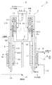
次に、上述したバーナ10、燃焼筒11、排ガス流路L1、改質部6、高温シフト反応部12、低温シフト反応部13、選択酸化反応部8、蒸発部9の配置関係について、より詳細に説明する。
Next, the arrangement relationship of the
図2に示されるように、燃焼筒11は、バーナ10の火炎を囲むようにバーナ10の下端部に設けられている。燃焼筒11は、バーナ10の燃焼ガスである排ガスを下側(一方の側)から排出する。改質部6は、燃焼筒11を囲むように筒状(ここでは、上述したように中心軸を軸Gとする円筒状外形)に設けられている。排ガス流路L1は、燃焼筒11の下側から燃焼筒11と改質部6との間を通って改質部6の上側(他方の側)で折り返され、かつ改質部6の外側を通って下側に延在するように筒状に設けられている。高温シフト反応部12は、改質部6を囲み、かつ排ガス流路L1のうち改質部の外側を通る部分L1aに囲まれるように筒状に設けられている。
As shown in FIG. 2, the
低温シフト反応部13は、排ガス流路L1のうち下側に延在する部分(延在部分)L1bに囲まれるように筒状に設けられている。換言すれば、低温シフト反応部13は、排ガス流路L1の部分L1bの内側(ここでは、径方向内側)において部分L1bに沿うように筒状に設けられている。蒸発部9は、排ガス流路L1の部分L1bを囲むように筒状に設けられている。選択酸化反応部8は、蒸発部9を囲むように筒状に設けられている。換言すれば、選択酸化反応部8は、排ガス流路L1の部分L1bの外側(ここでは、径方向外側)において部分L1bに沿うように筒状に設けられている。
The low temperature
なお、低温シフト反応部13を排ガス流路L1の部分L1bの内側に配置し、選択酸化反応部8を排ガス流路L1の部分L1bの外側に配置することで、選択酸化反応部8の放熱を促進させることができる。また、選択酸化反応部8の選択酸化触媒8xは、低温シフト反応部13の低温シフト触媒13xよりも通常少量となるため、前述の配置構成は、水素製造装置1の大型化を抑制する。
In addition, the low temperature
低温シフト反応部13の上端部(他方の側の端部)は、選択酸化反応部8の上端部よりも上側に位置している。蒸発部9の上端部は、高温シフト反応部12の下端部(一方の側の端部)の外側に位置している。そして、改質部6で改質ガスが生成されているときは、蒸発部9に貯留された水の水面WFは、低温シフト反応部13の上端部及び選択酸化反応部8の上端部よりも上側に位置するように調整される。
The upper end portion (the end portion on the other side) of the low temperature
なお、フィード部5は、燃焼筒11の下側において燃焼筒11に対向する位置から改質部6の下端部に至っている。改質部6で生成された改質ガスを流通させる改質ガス流路L2は、改質部6の上端部の外側から、高温シフト反応部12及び低温シフト反応部13を上側から下側へと通り、更に選択酸化反応部8を下側から上側へと通ってセルスタック20に至っている。
The
また、蒸発部9に導入される水を流通させる水流路L3は、改質ガス流路L2のうち選択酸化反応部8の下流側の部分に設けられた予熱部15を通って、蒸発部9の下端部に至っている。予熱部15は、蒸発部9に導入される水を、選択酸化反応部8から導出された改質ガスの熱によって予熱する。蒸発部9で生成された水蒸気を流通させる水蒸気流路L4は、蒸発部9の上端部から、原燃料を流通させる原燃料流路L5に合流してフィード部5に至っている。
Further, the water flow path L3 for circulating the water introduced into the evaporation section 9 passes through the preheating
上述の構成を有する水素製造装置1では、制御部30において以下の制御を実行することで、選択酸化反応部8から導出されるCO濃度を所定の上限値(例えば10ppm)以下としている。すなわち、水素製造装置1では、低温シフト触媒13xの温度に応じて所定の制御マップMを用い、低温シフト反応部13の低温シフト触媒13xの温度を所定温度以下とするために蒸発部9への水の供給量を変更することで、選択酸化反応部8から導出されるCO濃度を所定範囲内とする。
In the
具体的な制御部30の制御方法について、図4を参照しながら説明する。図4は、制御部の処理手順を示すフローチャートである。 A specific control method of the control unit 30 will be described with reference to FIG. FIG. 4 is a flowchart illustrating a processing procedure of the control unit.
図4に示すように、まず温度センサCによって計測された低温シフト反応部13の低温シフト触媒13xの温度情報が取得される(ステップS01)。低温シフト触媒13xの温度情報が取得されると、この取得された低温シフト触媒13xの温度情報が示す温度T1と基準温度Tとの温度差が求められる(ステップS02)。
As shown in FIG. 4, first, temperature information of the low
そして、制御マップMに基づいて、基準温度Tからの温度差に対応する水(プロセス水)の増加倍率が設定される(ステップS03)。具体的には、図3に示すように、例えば温度差が「15℃」である場合には、水の増加倍率が「1.2倍」に設定される。その後、設定された増加率に応じて水供給ポンプPが制御される(ステップS04)。これにより、低温シフト反応部13の低温シフト触媒13xの温度が所定の範囲内に設定され、これに伴い選択酸化反応部8から導出されるCO濃度が所定値に維持される。
Based on the control map M, an increase rate of water (process water) corresponding to the temperature difference from the reference temperature T is set (step S03). Specifically, as shown in FIG. 3, for example, when the temperature difference is “15 ° C.”, the water increase rate is set to “1.2 times”. Thereafter, the water supply pump P is controlled according to the set increase rate (step S04). As a result, the temperature of the low
以上説明したように、燃料電池システム100の水素製造装置1では、蒸発部9に導入する水の導入量を制御する制御部30によって、低温シフト触媒13xの温度を計測する温度センサCによって計測された低温シフト反応部13の低温シフト触媒13xの温度が予め設定された基準温度Tとなるように水供給ポンプPが蒸発部9に導入する水の導入量を制御している。このように、低温シフト反応部13の低温シフト触媒13xの温度を蒸発部9に導入する水の導入量によって予め設定された基準温度Tとすることで、低温シフト反応部13から導出されるCO濃度を所定値以下で維持することができる。そのため、選択酸化反応部8に導入する空気量を増量するといった制御を行わなくとも、選択酸化反応部8から導出されるCO濃度を所定の上限値以下とすることができる。したがって、改質ガスを安定的に供給でき、信頼性の向上を図ることができる。
As described above, in the
また、蒸発部9に導入する水の導入量によって低温シフト反応部13を基準温度Tに維持するため、機差(触媒量、ロット)、誤差(流量計、ポンプ)及び経年劣化等によって系全体の温度及びガス組成のバランスが多少変動した場合であっても、それぞれの要因が補正されるため、ロバスト性の向上を図ることができ、その結果、信頼性、耐久性の向上を図ることができる。
Further, since the low temperature
また、低温シフト反応部13が排ガス流路L1の部分L1bに囲まれるように筒状に設けられており、選択酸化反応部8が蒸発部9を介して排ガス流路L1の部分L1bを囲むように筒状に設けられている。そのため、水素製造装置1の起動時にバーナ10の燃焼ガスである排ガスが排ガス流路L1を流通させられると、排ガスの熱によって、改質部6及び高温シフト反応部12だけでなく、低温シフト反応部13、選択酸化反応部8及び蒸発部9も加熱されて昇温させられる。その後、蒸発部9に水が導入されると、加熱水蒸気の熱によって、改質部6、各シフト反応部12,13及び選択酸化反応部8が更に加熱されて昇温させられる。これにより、改質部6、各シフト反応部12,13及び選択酸化反応部8がそれぞれ適切な反応温度に昇温させられる。そして、蒸発部9で生成された水蒸気と共に原燃料が改質部6に導入され、選択酸化反応部8に空気が導入されると、一酸化炭素濃度が低下させられた改質ガスが生成され始める。このとき、排ガス流路L1の部分L1bでは、排ガスの熱だけでなく低温シフト反応部13の反応熱及び選択酸化反応部8の反応熱も蒸発部9に移動する。これにより、低温シフト反応部13及び選択酸化反応部8がそれぞれ適切な反応温度に維持される。このように、水素製造装置1及びその起動方法によれば、起動時に低温シフト反応部13及び選択酸化反応部8での電気ヒータの使用が不要となるので、起動エネルギの消費を抑制して、低温シフト反応部13及び選択酸化反応部8を素早く昇温させることができる。
Further, the low temperature
また、制御部30は、温度センサCによって計測された低温シフト反応部13の低温シフト触媒13xの温度T1と基準温度Tとの間に温度差がある場合に、温度差に対して基準値Sに基づき設定された増加倍率で蒸発部9に導入する水の導入量を増加させて、低温シフト反応部13の低温シフト触媒13xの温度を基準温度Tにする。このような構成によれば、低温シフト触媒13xと基準温度Tとの温度差に応じて水の増加倍率が設定されているので、低温シフト反応部13の低温シフト触媒13xの温度の変動に対応して蒸発部9への水の導入量を増加させることができる。したがって、低温シフト反応部13の低温シフト触媒13xの温度を基準温度Tで維持できる。
In addition, when there is a temperature difference between the temperature T1 of the low
また、増加倍率は、低温シフト反応部の触媒の温度と設定温度との温度差が大きくなるほど倍率が高くなるように設定されている。これにより、低温シフト反応部13の低温シフト触媒13xの温度が高くなるほど水供給ポンプから供給される水の量が増量されるため、より確実に低温シフト反応部13の低温シフト触媒13xの温度を基準温度Tで維持できる。
The increase rate is set so that the rate increases as the temperature difference between the temperature of the catalyst in the low temperature shift reaction section and the set temperature increases. As a result, the amount of water supplied from the water supply pump increases as the temperature of the low
本発明は、上記実施形態に限定されるものではない。例えば、上記実施形態では、制御マップMにおいて、原燃料の導入量によらず低温シフト触媒13xの目標温度(基準温度T)が一定の場合を例示したが、原燃料の導入量に応じて低温シフト触媒13xの目標温度が変更されてもよい。具体的には、図5を参照しながら説明する。図5は、他の変形例に係る制御マップを示す図である。
The present invention is not limited to the above embodiment. For example, in the above-described embodiment, the case where the target temperature (reference temperature T) of the low
図5に示すように、制御マップMAでは、原燃料の導入量と低温シフト触媒13xの温度の変動に応じて水の増加倍率が設定されており、原燃料の増加に伴い低温シフト触媒13xの目標温度が低下するように設定されている。制御マップMAでは、基準となる低温シフト触媒13xの目標温度(目標値)Gが設定されおり、この目標温度Gでは、水の増加倍率が1.0倍に設定されている。そして、制御マップMAでは、この目標温度Gの水の増加倍率を基準として、例えば低温シフト触媒13xの温度が目標温度Gに対して「+10℃」である場合には、水の増加倍率が「1.1倍」に設定されており、低温シフト触媒13xの温度が目標温度Gに対して「+20℃」である場合には、水の増加倍率が「1.3倍」に設定されており、低温シフト触媒13xの温度が目標温度Gに対して「+30℃」である場合には、水の増加倍率が「1.5倍」に設定されている。
As shown in FIG. 5, in the control map MA, the rate of increase of water is set according to the amount of raw fuel introduced and the temperature of the low
制御部30は、上記制御マップMAを用い、蒸発部9に導入する水の増加倍率を設定し、水供給ポンプPを制御する。これにより、蒸発部9に供給される水の量が増加されるため、低温シフト反応部13では、低温シフト触媒13xの出口の温度が所定範囲内の目標温度Gに維持される。
The control part 30 sets the increase rate of the water introduced into the evaporation part 9 using the control map MA, and controls the water supply pump P. As a result, the amount of water supplied to the evaporation unit 9 is increased, so that the temperature of the outlet of the low
また、上記実施形態では、水素製造装置は、改質ガス中の一酸化炭素をシフト反応させるものとして高温シフト反応部及び低温シフト反応部を備えているが、低温シフト反応部のみを備えるものであってもよい。 Moreover, in the said embodiment, although the hydrogen production apparatus is provided with the high temperature shift reaction part and the low temperature shift reaction part as what makes the carbon monoxide in reformed gas shift reaction, it is only provided with a low temperature shift reaction part. There may be.
また、水素製造装置の改質部は、水蒸気改質反応を利用するものに限定されず、原燃料及び水蒸気を用いて改質ガスを生成するものであれば、他の改質反応を利用するものであってもよい。また、水素製造装置の配置構成については、上記水素製造装置1を上下反転したような配置構成(例えば、バーナ10が下部に設置されて構成された水素製造装置)としてもよい。また、水素製造装置は、脱硫器を備えない場合もある。
Further, the reforming unit of the hydrogen production apparatus is not limited to the one using the steam reforming reaction, and other reforming reactions are used as long as the reformed gas is generated using raw fuel and steam. It may be a thing. Moreover, about the arrangement configuration of the hydrogen production apparatus, an arrangement arrangement in which the
ちなみに、上記の「筒状」とは、略円筒状だけでなく、略多角筒状を含むものである。また、略円筒状及び略多角筒状とは、円筒状及び多角筒状に概略等しいものや、円筒状及び多角筒状の部分を少なくとも含むもの等の広義の円筒状及び多角筒状を意味している。また、上記実施形態は、好ましいとして、中心軸を軸Gとする同軸構成とされているが、本発明は、略同軸又は軸Gに沿った構成とされていてもよい。 Incidentally, the above “tubular shape” includes not only a substantially cylindrical shape but also a substantially polygonal tubular shape. In addition, the substantially cylindrical shape and the substantially polygonal cylindrical shape mean a cylindrical shape and a polygonal cylindrical shape in a broad sense such as those substantially equal to the cylindrical shape and the polygonal cylindrical shape, and those including at least a cylindrical shape and a polygonal cylindrical shape. ing. Moreover, although the said embodiment is made into the coaxial structure which makes the center axis | shaft the axis | shaft G as a preferable, this invention may be set as the structure substantially along the axis | shaft or the axis | shaft G.
1…水素製造装置、6…改質部、8…選択酸化反応部、9…蒸発部、10…バーナ、11…燃焼筒、13…低温シフト反応部、15…予熱部、20…セルスタック(燃料電池スタック)、30…制御部、100…燃料電池システム、C…温度センサ(温度計測部)、L1…排ガス流路、L1a…部分、L1b…部分(延在部分)。
DESCRIPTION OF
Claims (6)
バーナと、
前記バーナの火炎を囲むように設けられ、前記バーナの排ガスを一方の側から排出する燃焼筒と、
前記燃焼筒を囲むように筒状に設けられ、前記原燃料及び前記水蒸気を改質反応させて前記改質ガスを生成する改質部と、
前記燃焼筒と前記改質部との間を通って前記改質部の他方の側で折り返され、かつ前記改質部の外側を通って一方の側に延在するように筒状に設けられ、前記燃焼筒の一方の側から排出された前記排ガスを流通させる排ガス流路と、
前記排ガス流路のうち一方の側に延在する延在部分に囲まれるように筒状に設けられ、前記改質部で生成された前記改質ガスを触媒によってシフト反応させて前記改質ガスの一酸化炭素濃度を低下させる低温シフト反応部と、
前記低温シフト反応部の前記触媒の温度を計測する温度計測部と、
前記延在部分を囲むように筒状に設けられ、貯留された水を周囲の熱によって加熱して前記水蒸気を生成する蒸発部と、
前記蒸発部を囲むように筒状に設けられ、前記低温シフト反応部でシフト反応させられた前記改質ガスを選択酸化反応させて前記一酸化炭素濃度を更に低下させる選択酸化反応部と、
前記蒸発部に導入する前記水の導入量を制御する制御部とを備え、
前記制御部は、前記温度計測部によって計測された前記低温シフト反応部の前記触媒の温度が予め設定された設定温度となるように前記蒸発部に導入する前記水の導入量を制御することを特徴とする水素製造装置。 A hydrogen production apparatus that generates a reformed gas containing hydrogen using raw fuel and steam,
With a burner,
A combustion cylinder provided so as to surround the flame of the burner, and exhausting the exhaust gas of the burner from one side;
A reforming section that is provided in a cylindrical shape so as to surround the combustion cylinder, and that reforms the raw fuel and the steam to generate the reformed gas;
It is provided in a cylindrical shape so as to be folded between the combustion cylinder and the reforming section on the other side of the reforming section and to extend to one side through the outside of the reforming section. An exhaust gas passage for circulating the exhaust gas discharged from one side of the combustion cylinder;
The reformed gas is provided in a cylindrical shape so as to be surrounded by an extending portion extending to one side of the exhaust gas flow path, and the reformed gas generated in the reforming section is shift-reacted by a catalyst. A low temperature shift reaction section for reducing the carbon monoxide concentration of
A temperature measuring unit for measuring the temperature of the catalyst in the low temperature shift reaction unit;
An evaporating section that is provided in a cylindrical shape so as to surround the extending portion, and that heats the stored water by ambient heat to generate the water vapor;
A selective oxidation reaction section that is provided in a cylindrical shape so as to surround the evaporation section, and that causes a selective oxidation reaction of the reformed gas that has undergone a shift reaction in the low temperature shift reaction section to further reduce the carbon monoxide concentration;
A control unit for controlling the amount of water introduced into the evaporation unit,
The control unit controls the amount of water introduced into the evaporation unit so that the temperature of the catalyst of the low temperature shift reaction unit measured by the temperature measurement unit becomes a preset temperature. Characteristic hydrogen production equipment.
前記水素製造装置によって生成された前記改質ガスを用いて発電を行う燃料電池スタックと、を備えることを特徴とする燃料電池システム。 The hydrogen production apparatus according to any one of claims 1 to 5,
A fuel cell system, comprising: a fuel cell stack that generates electric power using the reformed gas generated by the hydrogen production apparatus.
Priority Applications (2)
| Application Number | Priority Date | Filing Date | Title |
|---|---|---|---|
| JP2010078864A JP5409486B2 (en) | 2010-03-30 | 2010-03-30 | Hydrogen production apparatus and fuel cell system |
| PCT/JP2011/057686 WO2011122579A1 (en) | 2010-03-30 | 2011-03-28 | Device for producing hydrogen, and fuel-cell system |
Applications Claiming Priority (1)
| Application Number | Priority Date | Filing Date | Title |
|---|---|---|---|
| JP2010078864A JP5409486B2 (en) | 2010-03-30 | 2010-03-30 | Hydrogen production apparatus and fuel cell system |
Publications (2)
| Publication Number | Publication Date |
|---|---|
| JP2011207715A JP2011207715A (en) | 2011-10-20 |
| JP5409486B2 true JP5409486B2 (en) | 2014-02-05 |
Family
ID=44712274
Family Applications (1)
| Application Number | Title | Priority Date | Filing Date |
|---|---|---|---|
| JP2010078864A Expired - Fee Related JP5409486B2 (en) | 2010-03-30 | 2010-03-30 | Hydrogen production apparatus and fuel cell system |
Country Status (2)
| Country | Link |
|---|---|
| JP (1) | JP5409486B2 (en) |
| WO (1) | WO2011122579A1 (en) |
Families Citing this family (7)
| Publication number | Priority date | Publication date | Assignee | Title |
|---|---|---|---|---|
| JP5468713B1 (en) * | 2012-06-22 | 2014-04-09 | パナソニック株式会社 | Hydrogen generator and fuel cell system |
| US9144781B2 (en) | 2012-06-25 | 2015-09-29 | Panasonic International Property Management Co., Ltd. | Fuel processing device |
| US11434021B2 (en) | 2017-03-23 | 2022-09-06 | Bae Systems Plc | Electrical power generation on a vehicle |
| US11505328B2 (en) | 2017-03-23 | 2022-11-22 | Bae Systems Plc | Electrical power generation on a vehicle |
| GB2560771A (en) * | 2017-03-23 | 2018-09-26 | Bae Systems Plc | Electrical power generation on a vehicle |
| GB2560773A (en) * | 2017-03-23 | 2018-09-26 | Bae Systems Plc | Electrical power generation on a vehicle |
| JP2019040663A (en) * | 2017-08-22 | 2019-03-14 | 京セラ株式会社 | Power generation device, control device, and control program |
Family Cites Families (4)
| Publication number | Priority date | Publication date | Assignee | Title |
|---|---|---|---|---|
| JP2003321206A (en) * | 2002-05-08 | 2003-11-11 | Tokyo Gas Co Ltd | Single tubular cylinder type reforming apparatus |
| JP2007063102A (en) * | 2005-09-02 | 2007-03-15 | Toshiba Fuel Cell Power Systems Corp | Temperature control system and temperature control method for co converter unit |
| JP2008189509A (en) * | 2007-02-02 | 2008-08-21 | Idemitsu Kosan Co Ltd | Reforming unit and fuel cell system |
| JP2008189507A (en) * | 2007-02-02 | 2008-08-21 | Idemitsu Kosan Co Ltd | Reforming unit and fuel cell system |
-
2010
- 2010-03-30 JP JP2010078864A patent/JP5409486B2/en not_active Expired - Fee Related
-
2011
- 2011-03-28 WO PCT/JP2011/057686 patent/WO2011122579A1/en active Application Filing
Also Published As
| Publication number | Publication date |
|---|---|
| WO2011122579A1 (en) | 2011-10-06 |
| JP2011207715A (en) | 2011-10-20 |
Similar Documents
| Publication | Publication Date | Title |
|---|---|---|
| JP5409486B2 (en) | Hydrogen production apparatus and fuel cell system | |
| JP5164441B2 (en) | Starting method of fuel cell system | |
| JP5325403B2 (en) | Starting method of fuel cell system | |
| JP5610812B2 (en) | Hydrogen production apparatus and fuel cell system | |
| JP5214230B2 (en) | Starting method of fuel cell system | |
| US20100221619A1 (en) | Fuel cell system | |
| JP5340657B2 (en) | Hydrogen generator, fuel cell system, and operation method of hydrogen generator | |
| JP2009079155A (en) | Liquid fuel desulfurization apparatus and liquid fuel desulfurization system | |
| JP5536636B2 (en) | Fuel cell system | |
| JP4902165B2 (en) | Fuel cell reformer and fuel cell system comprising the fuel cell reformer | |
| JP2007022826A (en) | Hydrogen generation unit and fuel cell system | |
| JP5536635B2 (en) | Fuel cell system | |
| JP5634729B2 (en) | Hydrogen production apparatus and fuel cell system | |
| JP5613432B2 (en) | Hydrogen production apparatus, fuel cell system, and hydrogen production apparatus start-up method | |
| JP5538028B2 (en) | Hydrogen production apparatus and fuel cell system | |
| JP5462687B2 (en) | Hydrogen production apparatus and fuel cell system | |
| JP2004175637A (en) | Co remover and hydrogen production apparatus | |
| JP5597426B2 (en) | Hydrogen production apparatus and fuel cell system | |
| JP5257186B2 (en) | Fuel cell power generator | |
| JP5562700B2 (en) | Hydrogen production apparatus and fuel cell system | |
| WO2012091037A1 (en) | Fuel cell system | |
| JP2007326725A (en) | Apparatus for producing hydrogen and fuel cell system | |
| JP2010189198A (en) | Maintenance method of hydrogen generator | |
| JP2008143751A (en) | Fuel processor and its operation method | |
| JP2009143745A (en) | Hydrogen generator |
Legal Events
| Date | Code | Title | Description |
|---|---|---|---|
| A621 | Written request for application examination |
Free format text: JAPANESE INTERMEDIATE CODE: A621 Effective date: 20120629 |
|
| A01 | Written decision to grant a patent or to grant a registration (utility model) |
Free format text: JAPANESE INTERMEDIATE CODE: A01 Effective date: 20131029 |
|
| A61 | First payment of annual fees (during grant procedure) |
Free format text: JAPANESE INTERMEDIATE CODE: A61 Effective date: 20131105 |
|
| LAPS | Cancellation because of no payment of annual fees |