EP2732770A1 - Nadellose Injektionsvorrichtung - Google Patents
Nadellose Injektionsvorrichtung Download PDFInfo
- Publication number
- EP2732770A1 EP2732770A1 EP12192953.3A EP12192953A EP2732770A1 EP 2732770 A1 EP2732770 A1 EP 2732770A1 EP 12192953 A EP12192953 A EP 12192953A EP 2732770 A1 EP2732770 A1 EP 2732770A1
- Authority
- EP
- European Patent Office
- Prior art keywords
- fluid
- injection device
- wall surface
- energy store
- valve
- Prior art date
- Legal status (The legal status is an assumption and is not a legal conclusion. Google has not performed a legal analysis and makes no representation as to the accuracy of the status listed.)
- Granted
Links
Images

Classifications
-
- A—HUMAN NECESSITIES
- A61—MEDICAL OR VETERINARY SCIENCE; HYGIENE
- A61M—DEVICES FOR INTRODUCING MEDIA INTO, OR ONTO, THE BODY; DEVICES FOR TRANSDUCING BODY MEDIA OR FOR TAKING MEDIA FROM THE BODY; DEVICES FOR PRODUCING OR ENDING SLEEP OR STUPOR
- A61M5/00—Devices for bringing media into the body in a subcutaneous, intra-vascular or intramuscular way; Accessories therefor, e.g. filling or cleaning devices, arm-rests
- A61M5/178—Syringes
- A61M5/30—Syringes for injection by jet action, without needle, e.g. for use with replaceable ampoules or carpules
-
- A—HUMAN NECESSITIES
- A61—MEDICAL OR VETERINARY SCIENCE; HYGIENE
- A61B—DIAGNOSIS; SURGERY; IDENTIFICATION
- A61B17/00—Surgical instruments, devices or methods
- A61B17/00234—Surgical instruments, devices or methods for minimally invasive surgery
-
- A—HUMAN NECESSITIES
- A61—MEDICAL OR VETERINARY SCIENCE; HYGIENE
- A61B—DIAGNOSIS; SURGERY; IDENTIFICATION
- A61B17/00—Surgical instruments, devices or methods
- A61B17/32—Surgical cutting instruments
- A61B17/3203—Fluid jet cutting instruments
-
- A—HUMAN NECESSITIES
- A61—MEDICAL OR VETERINARY SCIENCE; HYGIENE
- A61B—DIAGNOSIS; SURGERY; IDENTIFICATION
- A61B17/00—Surgical instruments, devices or methods
- A61B17/32—Surgical cutting instruments
- A61B17/3203—Fluid jet cutting instruments
- A61B17/32037—Fluid jet cutting instruments for removing obstructions from inner organs or blood vessels, e.g. for atherectomy
-
- A—HUMAN NECESSITIES
- A61—MEDICAL OR VETERINARY SCIENCE; HYGIENE
- A61B—DIAGNOSIS; SURGERY; IDENTIFICATION
- A61B17/00—Surgical instruments, devices or methods
- A61B17/00234—Surgical instruments, devices or methods for minimally invasive surgery
- A61B2017/00238—Type of minimally invasive operation
- A61B2017/00269—Type of minimally invasive operation endoscopic mucosal resection EMR
-
- A—HUMAN NECESSITIES
- A61—MEDICAL OR VETERINARY SCIENCE; HYGIENE
- A61B—DIAGNOSIS; SURGERY; IDENTIFICATION
- A61B17/00—Surgical instruments, devices or methods
- A61B2017/00535—Surgical instruments, devices or methods pneumatically or hydraulically operated
- A61B2017/00544—Surgical instruments, devices or methods pneumatically or hydraulically operated pneumatically
-
- A—HUMAN NECESSITIES
- A61—MEDICAL OR VETERINARY SCIENCE; HYGIENE
- A61B—DIAGNOSIS; SURGERY; IDENTIFICATION
- A61B17/00—Surgical instruments, devices or methods
- A61B2017/00535—Surgical instruments, devices or methods pneumatically or hydraulically operated
- A61B2017/00544—Surgical instruments, devices or methods pneumatically or hydraulically operated pneumatically
- A61B2017/00548—Gas cartridges therefor
-
- A—HUMAN NECESSITIES
- A61—MEDICAL OR VETERINARY SCIENCE; HYGIENE
- A61B—DIAGNOSIS; SURGERY; IDENTIFICATION
- A61B17/00—Surgical instruments, devices or methods
- A61B17/32—Surgical cutting instruments
- A61B2017/320044—Blunt dissectors
-
- F—MECHANICAL ENGINEERING; LIGHTING; HEATING; WEAPONS; BLASTING
- F04—POSITIVE - DISPLACEMENT MACHINES FOR LIQUIDS; PUMPS FOR LIQUIDS OR ELASTIC FLUIDS
- F04C—ROTARY-PISTON, OR OSCILLATING-PISTON, POSITIVE-DISPLACEMENT MACHINES FOR LIQUIDS; ROTARY-PISTON, OR OSCILLATING-PISTON, POSITIVE-DISPLACEMENT PUMPS
- F04C2270/00—Control; Monitoring or safety arrangements
- F04C2270/04—Force
- F04C2270/041—Controlled or regulated
Definitions
- the invention relates to an injection device for needleless fluid injection, in particular for injection or elevation of the mucosa of the gastrointestinal tract or for similar applications.
- the device has a reservoir for a drug which is connected to a hollow needle. This is retracted at rest in a housing. A tensioned spring present in the housing serves to cause the hollow needle to rattle when triggered and to expel the medicament via the hollow needle.
- devices which serve for the needleless injection of a fluid under the mucosa.
- US 2009/0157114 A1 an endoscope with a probe for needle-less injection of the mucosa.
- the probe emits a jet of sodium chloride solution, which penetrates into the tissue due to its small cross-section and its pressure (or momentum).
- a pump unit or optionally a force-enhancing lever may be provided.
- the injection device serves to generate a fluid jet by means of a fluid applicator, which penetrates into the biological tissue without the use of a hollow needle and generates a fluid depot there.
- the fluid applicator is preferably formed as a flexible, thin probe that can be inserted through a tube, endoscope, or other suitable means into a body cavity to perform the desired needleless injection.
- the fluid applicator may also be formed as a hand instrument with a handle and a nozzle, via which the user initiates the ejection of a fluid jet.
- the nozzle provided for ejecting the fluid jet can be designed to generate a substantially cylindrical sharp jet or other beam shapes suitable for Paremchym resolution (cone beam, fan beam, hollow beam and the like). It is also possible to use the fluid jet generated by the device according to the invention for the dissection of tissue.
- the fluid line leading to the supply of the fluid outlet opening is connected to a storage chamber which belongs to a fluid supply device.
- the fluid is preferably physiological saline.
- the storage chamber has at least one first movable wall surface, which can be acted upon by a force generated by a drive device. Preferably, this force is substantially constant in time, so that at the fluid outlet opening the fluid can emerge at a substantially constant speed and under a substantially constant pressure.
- the drive device has an energy store. Thus, it can be handled independently of stationary devices, which brings a high flexibility in the use of the patient.
- the energy storage also replaces people who would otherwise have to apply by hand the high fluid pressure required for needleless injection.
- the fluid is under a pressure of 20 bar to 40 bar, for example, it has a pressure of substantially constant 30 bar.
- the energy storage may include or be formed by a biased spring acting on a movable wall of the storage chamber.
- the length of the spring is preferably greater than that of the movable wall surface during the ejection of the fluid to be traversed way.
- the change in the spring force is limited in the expansion of the same, so that the resulting pressure difference between full pantry and nearly empty pantry remains below a tolerable tolerance of, for example, some bar.
- the energy storage device may be an electric battery or an accumulator, which is connected via a switch to an electric motor which is connected directly or via a gear to the movable wall surface of the storage chamber.
- the capacity of the battery is preferably at least sized so that the energy supplied by it is sufficient for ejecting the entire fluid volume of the storage chamber.
- the energy store is designed as a pressure source.
- the pressure source is understood by a storage volume with a pressurized compressible fluid.
- the fluid may be wholly or partly in the gaseous or in the liquid state.
- the fluid used is preferably a fluid which is present in liquid form at room temperature and storage pressure, such as carbon dioxide (CO 2 ), nitrogen oxide (dinitrogen monoxide or the like). During expansion, it evaporates completely or partially.
- CO 2 carbon dioxide
- nitrogen oxide dinitrogen monoxide or the like
- the drive means preferably comprises an expansion chamber having a second movable wall surface for expanding the driving fluid, the expansion chamber being connected or connectable to the pressure source. Once the pressure source is connected to the expansion chamber is, the injection device is ready. The pressure exerted by the driving fluid on the second movable wall surface pressure generates a force with which the first movable wall surface of the storage chamber can be acted upon. If at least a portion of the driving fluid in the liquid phase is present in the liquid phase, a constant working pressure can be maintained in the expansion chamber during expansion, ie during ejection of the fluid. Accordingly, the fluid is subjected to constant pressure.
- a gas pressure accumulator is preferably a CO 2 capsule, an N 2 O capsule or other gas-filled capsule with a gas-tight seal for use.
- the capsule may be associated with a receptacle with a piercing device for the unsealing of the capsule. Once the capsule is inserted into a corresponding receptacle and activated by means of the piercing device, the injection device is ready for use.
- the first and second movable wall surfaces have different surface areas. In this way, a pressure adjustment causes and, for example, with a up to 60 bar having CO 2 capsule, a constant ejection pressure of, for example, 30 bar can be achieved.
- the area ratio of the wall surfaces to each other in this case is 1: 2. Other wall surface ratios may be provided. Thus, both an increase in pressure and a pressure reduction can be achieved.
- the two surfaces are arranged on mutually remote pistons, between which a ventilation opening is provided.
- a ventilation opening is provided.
- leakage gas escaping from the piston of the expansion chamber can escape without entering the storage chamber. Damage to the patient by disruptive gases are hereby locked out.
- a valve is provided between the nozzle and the storage chamber. It may be a check valve, via which the fluid flow can be released or shut off. In a convenient embodiment, the valve may also be designed as a throttle valve. It allows the user to regulate the strength of the exiting fluid jet.
- the valve is located near the storage chamber.
- the fluid line When commissioning the injection device, the fluid line must be vented. This is done by probeweises the valve until the entire fluid line is filled with fluid.
- the fluid outlet opening can also be provided with a sterility closure and the fluid line can be prefilled with fluid. This further facilitates the handling.
- Each of the injection devices described above may be wholly or partially formed as a disposable device.
- a housing containing the storage chamber and the drive means may be provided sterile plastic, wherein the storage chamber may be filled with sodium chloride solution or another fluid.
- a tensioned spring may be located in the housing, which is held by the locking device.
- a battery, an electric motor and a transmission may be accommodated in the housing.
- a sterile pack may contain both the injection device and the pressure accumulator, for example in the form of a CO 2 capsule or other capsule. The capsule is used for activation in a corresponding receptacle of the injection device and broached. It is also possible to use non-sterile storage capsules (eg NO 2 , CO 2 or the like) from the consumer goods sector.
- non-sterile storage capsules eg NO 2 , CO 2 or the like
- Illustrated injection device 10 comprises a fluid applicator 11 and a fluid supply device 12 for supplying the fluid applicator 11 with a fluid.
- the fluid is preferably a physiological saline solution (NaCl solution) expelled from the fluid applicator 11 in a suitable jet shape.
- a physiological saline solution NaCl solution
- the fluid applicator 11 may, as in FIG. 1 schematically illustrated, be provided for open surgical application and correspondingly have a handle 13 and a nozzle shaft 14 extending therefrom.
- On the handle 13 may be an actuator, for example.
- a button 15 may be provided, via which a supply of the nozzle shaft 14 releasing or blocking valve or a regulating valve is actuated.
- a closed here by a protective cap 16 fluid outlet opening 17 may be attached, which can leak a fluid jet of the desired shape.
- the fluid outlet opening 17 is preferably formed by a nozzle.
- To the fluid applicator 11 further includes a fluid line 18, which connects the fluid applicator 11 with the fluid supply device 12.
- the fluid conduit 18 ultimately passes the fluid through the handle 13 to the nozzle stem 14 and its nozzle.
- FIG. 1 illustrates a fluid applicator 11 for open surgical application
- FIG. 2 a fluid applicator 11 for endoscopic application illustrated. It essentially comprises the fluid line 18, which here forms a thin flexible plastic tube is that can be pushed through a lumen of an endoscope.
- the fluid outlet opening 17 is arranged. If necessary, the outlet opening can be defined by a nozzle.
- the fluid supply device 12 serves to supply the fluid applicator 11 with fluid that is under a substantially constant pressure. Both the fluid applicator 11 after FIG. 1 as well as the fluid applicator 11 after FIG. 2 can be supplied with fluid from each of the fluid delivery devices 12 described below.
- FIG. 3 shows, the fluid supply device 12 to a storage chamber 20 which is completely filled with a suitable fluid 21.
- the storage chamber 20 has an outlet 22 to which the fluid line 18 is connected via a valve 23.
- the valve 23 may be a switching valve, which can take only the two positions “open” and “closed”. Alternatively, it may be a throttle valve, with the various flow resistances and thus different flow rates are adjustable.
- the valve may include an operator or actuator 24 attached to a housing of the fluid supply device 12.
- the storage chamber 20 is formed by a receiving space, which has, for example, the shape of a cylinder, which is closed at one side by a movable piston 25.
- the piston closes the storage chamber 20 with a wall surface 26 which is movable relative to the rest of the cylinder by the piston 25 is sealed against the cylinder displaceable.
- the piston 25 is via a power transmission means, such as a pin, a plunger, a rod 27 or The like, with a drive device 28 which includes an energy storage 29.
- the drive device 28 also comprises an expansion chamber 30, which has at least one movable wall surface 31.
- the ratio of the wall surfaces 26, 31 to each other is preferably different from one.
- the movable wall surface 31 may be formed by the end face of a sealingly mounted in a cylinder 32 piston 33. This is connected via the rod 27 or other power transmission means to the piston 25.
- the rod 27 extends through a gap 34, which is completely or partially enclosed by the housing, which encloses the storage chamber 20 and the expansion chamber 30.
- the intermediate space 34 is preferably ventilated to the atmosphere, for which purpose at least one ventilation opening 35 is provided.
- the energy store 29 forms a pressure source 36, for example in the form of a CO 2 capsule 37.
- a pressure-resistant container which is provided at a neck-like end 38 with a seal 39.
- the seal 39 can be pierced to release the gas present in the pressure source or the pressure vessel 36 by means of a Materialstechnadel 40, which is part of a container receptacle.
- the container receptacle has sealing means to receive the pressure vessel 36 sealed at its neck or end 38.
- the Aufbrechadel 40 pierces the seal 39, whereby the thus released pressurized gas via a channel 41 or directly ( Fig. 4 ) can be directed into the expansion chamber 30.
- the injection device 10 described so far operates as follows:
- the fluid supply device 12 is provided with a filled storage chamber 20.
- the pistons 25, 33 are thus in FIG. 3 in left position.
- the valve 23 is closed and the fluid line 18 initially empty.
- a preinstalled pressure vessel already present in the receptacle is pierced by means of a suitable mechanism by moving it against the Aufstechnadel 40 or by the Aufstechnadel is moved.
- the mechanism may e.g. be a lever-operated eccentric on which the neck of the opposite end 38 of the pressure vessel 36 is supported.
- Other mechanisms such as toggle arrangements or the like may be provided.
- the pressure vessel 36 is a commercially available CO 2 capsule with a charge of, for example, 12 g CO 2 , a pressure of 55 bar to 60 bar directly acts on the wall surface 31 FIG. 3 rightward force is transmitted to the piston 25 via the rod 27. Due to the diameter ratio of the pistons 33, 25 to each other, a desired fluid pressure of, for example, 30 bar can be produced. In this case, the wall surface 26 has twice the area as the wall surface 31.
- the injection device 10 is now ready for operation. Depending on the design of the fluid applicator 11, this can by appropriate handling of the handle 13 and, if necessary, actuation of the button 15 (if available). If a sharp fluid jet emerges from the fluid outlet opening 17, it can penetrate into a biological tissue and be used there, for example for injecting the mucosa. Other applications for injecting and submerging tissues are possible.
- the user can, for example, with the exiting beam also dissolve organ tissue.
- the fluid outlet opening 17 can also be designed so that other beam shapes, for example, fan beams or the like are generated.
- the fluid supply can be sized to 200 ml to 300 ml. Such a fluid supply can be ejected with a single CO 2 capsule 37 (eg 12 g) with a pressure of almost 30 bar, which is almost constant. This results in reliable and constant operating conditions for the user. Overall, the injection device 10 is very easy to handle and can be used independently of external energy or by the skill of an assistant.
- FIG. 4 illustrates this with an example in which the storage chamber 20 and its piston 25 are designed as a separate handle assembly in the manner of a pressure-resistant syringe. This is inserted into a socket of the housing, wherein the rod 27 presses against the piston 25.
- the chamber 30 is pressurized, whereby the rod 27 presses against the piston 25 with a substantially constant force.
- the valve 23 may be disposed in the handle 13 or elsewhere of the fluid line 18.
- the storage chamber 20 is empty, it can be replaced by a sterile, full.
- the CO 2 capsule 37 can be disposed of, whereby the expansion chamber 30 is first depressurized.
- the piston 25 can be pushed back to its left rest position.
- a new pantry 20, ie a new syringe and a new CO 2 capsule 37 are inserted into the housing, whereby the fluid supply device 12 is in turn ready for operation.
- reusable devices may be connected to the expansion chamber 30 and a residual pressure relief valve to drain existing residual propellant fluid safely.
- the storage chamber 20 are arranged in the expansion chamber 30.
- the storage chamber 20 may be formed, for example, by a bag or other compressible container which is connected to the outlet 22.
- the inner surface of the bag forms the first movable wall surface 26.
- the outside of the bag forms the two movable wall surface 31.
- a pressure vessel 36 serves as an energy storage 29 for pressurizing the expansion chamber 30.
- the bag containing the fluid supply can be designed as a disposable product, while the housing enclosing the chamber 30 and accommodating the pressure container 36 can be designed for multiple use. Alternatively, these parts can be designed as a disposable product.
- an outlet opening 42 leading into the interior of the storage chamber 20 is provided at the connection 22, which constitutes a flow restriction and has, for example, only a diameter of one millimeter or less.
- This restriction ensures that a completely emptied bag with its flexible wall closes the corresponding outlet opening 42.
- the cross-sectional area of the outlet opening 42 is preferably so low that the bag wall opposite to the discharge port 42 2 capsule 37 with certainty does not tear under pressure of CO.
- the diameter of the outlet opening 42 for this purpose is less than the wall thickness of the storage chamber 20 enclosing bag.
- FIG. 6 illustrates a fluid supply device 12 with an energy storage 29 in the form of a spring store.
- an energy storage 29 in the form of a spring store.
- the fluid 21 is pressurized via the piston 25.
- the piston 25 via a traction means.
- a pull rod 44 and a locking device 45 to lock in the housing.
- the pull rod 44 receives the force of the compression spring 43.
- the locking device 45 is released, for example, by tearing off or removing a blocking pin, the spring force acts on the piston and pressurizes the fluid 21.
- the fluid 21 can be released via the valve 23 and flow out controlled via the line 18.
- the fluid supply device 12 can be designed as a refillable product or as a disposable product.
- an electric battery 46 or a battery, a supercapacitor or the like which serves to feed a motor 47.
- the motor 47 actuates the piston 25 via a gear.
- the gear is preferably a reduction gear, which moves the piston 25, for example via a spindle-threaded drive 48.
- a switch 49 is used to activate the motor 47.
- the motor 47 and its feeding device are tuned to each other so that the motor 47 can be set under current for a long period of time (several minutes).
- the motor 47 is designed as a torque motor, so that it can be operated at zero speed as a torque source.
- the injection device 10 has a fluid applicator 11, which is fed by a fluid supply device 12, which contains an energy store 29.
- a fluid supply device 12 which contains an energy store 29.
- this is designed as a pressure vessel 36.
- the gas pressure originating from this pressure vessel 36 acts either directly on a container prefilled with the liquid or the fluid (eg isotonic NaCl solution) ( FIG. 5 ) or indirectly ( FIG. 3, 4 ).
- the ejected liquid is thus placed under constant pressure.
- the check valve 23 may also be a throttle valve, whereby the intensity of the effect can be varied by the user.
- the invention provides the basis for realizing an injection device which can be produced very inexpensively and which is always available.
- the user merely has to release the system, for example by staking the pressure vessel 36, in order then to be able to inject liquid directly or metered via the fluid line 18, ie the fluid applicator 11.
- the handling of both the Entêtns and the operation of the locking or throttle valve 23 is simple and intuitive. It is also possible to design the entire injection device 10 as a single-use system and to prefill the fluid applicator 11 as far as its fluid outlet opening.
- a sterile closure at the distal end of the fluid applicator 12 may be be formed by a protective cap 16.
Landscapes
- Health & Medical Sciences (AREA)
- Life Sciences & Earth Sciences (AREA)
- Surgery (AREA)
- Animal Behavior & Ethology (AREA)
- Biomedical Technology (AREA)
- Heart & Thoracic Surgery (AREA)
- Engineering & Computer Science (AREA)
- General Health & Medical Sciences (AREA)
- Public Health (AREA)
- Veterinary Medicine (AREA)
- Molecular Biology (AREA)
- Medical Informatics (AREA)
- Nuclear Medicine, Radiotherapy & Molecular Imaging (AREA)
- Vascular Medicine (AREA)
- Anesthesiology (AREA)
- Hematology (AREA)
- Infusion, Injection, And Reservoir Apparatuses (AREA)
Abstract
Description
- Die Erfindung betrifft eine Injektionsvorrichtung zur nadellosen Fluidinjektion, insbesondere zu Unterspritzung bzw. Elevation der Mucosa des Gastrointestinaltrakts oder für ähnliche Anwendungen.
- Zur Applikation von Arzneimitteln sind automatische Injektionsgeräte bekannt, die mittels Federspeicher und Nadel arbeiten. Ein Beispiel dafür ist der
DE 69533811 T2 zu entnehmen. Das Gerät weist einen Vorratsbehälter für ein Medikament auf, der mit einer Hohlnadel verbunden ist. Diese ist im Ruhezustand in ein Gehäuse zurückgezogen. Eine in dem Gehäuse vorhandene gespannte Feder dient dazu, bei Auslösung die Hohlnadel vorschnellen zu lassen und das Medikament über die Hohlnadel auszustoßen. - Darüberhinaus sind Geräte bekannt, die zur nadellosen Injektion eines Fluids unter die Mucosa dienen. Zum Beispiel offenbart die
US 2009/0157114 A1 ein Endoskop mit einer Sonde zur nadellosen Unterspritzung der Mucosa. Die Sonde stößt dazu einen Strahl Natriumchloridlösung aus, der aufgrund seines geringen Querschnitts und seines Drucks (bzw. Impulses) in das Gewebe eindringt. Zur Förderung der Natriumchloridlösung und zur Erzeugung des entsprechenden Drucks kann eine Pumpeinheit oder gegebenenfalls ein kraftverstärkender Hebel vorgesehen sein. - Die Anwendung dieses Prinzips setzt ein speisendes Gerät mit einer entsprechenden Pumpeinheit voraus. Wird zur Druckerzeugung ein kraftverstärkender Hebel, gegebenenfalls in Verbindung mit einer entsprechenden druckfesten Spritze, genutzt, ist die permanente Druckerzeugung durch Ausübung einer Handkraft z.B. durch einen Assistenten umständlich.
- Davon ausgehend ist es Aufgabe der Erfindung, eine Injektionsvorrichtung zu schaffen, die leicht und komfortabel zu handhaben ist und geringen technischen Aufwand erfordert.
- Diese Aufgabe wird mit der erfindungsgemäßen Injektionsvorrichtung gelöst, die insbesondere zur nadellosen Unterspritzung bzw. Elevation der Mucosa des Gastrointestinaltrakts eingerichtet, jedoch auch bei anderen vergleichbaren Aufgabe genutzt werden kann. Die Injektionsvorrichtung dient dazu, mittels eines Fluidapplikators einen Fluidstrahl zu erzeugen, der ohne Nutzung einer Hohlnadel in das biologische Gewebe eindringt und dort ein Flüssigkeitsdepot erzeugt. Der Fluidapplikator ist vorzugsweise als flexible dünne Sonde ausgebildet, die durch einen Schlauch, ein Endoskop oder andere geeignete Mittel hindurch in eine Körperhöhle eingeführt werden kann, um dort die gewünschte nadellose Injektion vorzunehmen. Für die offenchirurgische Anwendung kann der Fluidapplikator jedoch auch als Handinstrument mit einem Griff und einer Düse ausgebildet sein, über die der Anwender das Ausstoßen eines Fluidstrahls veranlasst. Unabhängig davon, ob der Fluidapplikator als flexible Sonde oder als Handinstrument ausgebildet ist, kann die zum Ausstoßen des Fluidstrahls vorgesehene Düse einen im Wesentlichen zylindrischen scharfen Strahl oder auch andere beispielsweise zur Paremchymauflösung geeignete Strahlformen erzeugend (Kegelstrahl, Fächerstrahl, Hohlstrahl und dergleichen) ausgebildet sein. Es ist auch möglich, den von der erfindungsgemäßen Vorrichtung erzeugte Fluidstrahl zur Dissektion von Gewebe zu verwenden.
- Die zur Speisung der Fluidaustrittsöffnung führende Fluidleitung ist mit einer Vorratskammer verbunden, die zu einer Fluidliefereinrichtung gehört. Das Fluid ist vorzugsweise physiologische Kochsalzlösung. Die Vorratskammer weist zumindest eine erste bewegliche Wandfläche auf, die mit einer von einer Antriebseinrichtung erzeugten Kraft beaufschlagbar ist. Vorzugsweise ist diese Kraft zeitlich im Wesentlichen konstant, so dass an der Fluidaustrittsöffnung das Fluid mit im Wesentlichen konstanter Geschwindigkeit und unter im Wesentlichen konstantem Druck austreten kann.
- Die Antriebseinrichtung weist einen Energiespeicher auf. Damit kann sie unabhängig von stationären Geräten gehandhabt werden, was eine hohe Flexibilität beim Einsatz am Patienten mit sich bringt. Der Energiespeicher ersetzt auch Hilfspersonen, die sonst den zur nadellosen Injektion erforderlichen hohen Fluiddruck von Hand aufbringen müssten. Vorzugsweise steht das Fluid unter einem Druck von 20 bar bis 40 bar, beispielsweise hat es einen Druck von im Wesentlichen konstant 30 bar.
- Als Energiespeicher können prinzipiell unterschiedliche Speicherarten für unterschiedliche Energien genutzt werden. Zum Beispiel kann der Energiespeicher eine gespannte Feder enthalten oder durch eine solche gebildet sein, die auf eine bewegliche Wand der Vorratskammer einwirkt. Die Länge der Feder ist dabei vorzugsweise größer als der von der beweglichen Wandfläche beim Ausstoßen des Fluids zu durchlaufende Weg. Dadurch wird die Änderung der Federkraft bei der Expansion derselben begrenzt, so dass der entstehende Druckunterschied zwischen voller Vorratskammer und nahezu leerer Vorratskammer unterhalb einer zulässigen Toleranz von beispielsweise einigen Bar bleibt.
- Es ist möglich, der Feder eine lösbare Arretierung zuzuordnen und das Fluid erst dann unter Druck setzt, wenn die Arretierung gelöst wird. Im Ruhezustand nimmt die Arretierung die von der gespannten Feder ausgehende Kraft auf. Wird die Arretierung gelöst, wirkt die Feder auf die bewegliche Wand ein und setzt das Fluid unter Druck, womit die Arbeitsbereitschaft der Injektionsvorrichtung hergestellt ist.
- Alternativ kann der Energiespeicher eine elektrische Batterie oder ein Akkumulator sein, die über einen Schalter mit einem Elektromotor verbunden ist, der direkt oder über ein Getriebe mit der beweglichen Wandfläche der Vorratskammer verbunden ist. Die Kapazität der Batterie ist vorzugsweise wenigstens so groß bemessen, dass die von ihr gelieferte Energie zum Ausstoßen des gesamten Fluidvolumens der Vorratskammer ausreicht.
- Bei einer bevorzugten Ausführungsform ist der Energiespeicher als Druckquelle ausgebildet. Die Druckquelle wird durch ein Vorratsvolumen mit einem unter Druck stehenden kompressiblen Fluid verstanden. Das Fluid kann ganz oder teilweise in gasförmigem oder in flüssigem Zustand vorliegen. Vorzugsweise wird als Fluid ein bei Zimmertemperatur und Speicherdruck in flüssiger Form vorliegendes Fluid wie Kohlendioxid (CO2), Stickstoffoxid (Distickstoffmonoxid o.ä.) verwendet. Bei der Expansion verdampft es ganz oder teilweise. Die Anwendung anderer (nichtsiedender) Fluide (Stickstoff, Argon oder dergleichen) ist möglich.
- Die Antriebseinrichtung umfasst zur Expansion des treibenden Fluids vorzugsweise eine Expansionskammer mit einer zweiten beweglichen Wandfläche, wobei die Expansionskammer mit der Druckquelle verbunden oder verbindbar ist. Sobald die Druckquelle mit der Expansionskammer verbunden ist, ist die Injektionsvorrichtung betriebsbereit. Der von dem treibenden Fluid auf die zweite bewegliche Wandfläche ausgeübte Druck erzeugt eine Kraft, mit der die erste bewegliche Wandfläche der Vorratskammer beaufschlagbar ist. Ist in der Druckquelle wenigstens ein Teil des treibenden Fluids in flüssiger Phase vorhanden, kann in der Expansionskammer während der Expansion, d.h. während des Aussto-βens des Fluid, ein konstanter Arbeitsdruck aufrechterhalten werden. Entsprechend wird das Fluid mit konstantem Druck beaufschlagt.
- Als Gasdruckspeicher kommt vorzugsweise eine CO2-Kapsel, eine N2O-Kapsel oder eine andere gasgefüllte Kapsel mit einer gasdichten Versiegelung zur Anwendung. Der Kapsel kann eine Aufnahme mit einer Durchstecheinrichtung für die Entsiegelung der Kapsel zugeordnet sein. Sobald die Kapsel in eine entsprechende Aufnahme eingesetzt und mittels der Durchstecheinrichtung aktiviert ist, ist die Injektionsvorrichtung betriebsbereit. Vorzugsweise weisen die erste und die zweite bewegliche Wandfläche unterschiedliche Flächeninhalte auf. Auf diese Weise kann eine Druckanpassung bewirkt und beispielsweise mit einer bis zu 60 bar aufweisenden CO2-Kapsel ein konstanter Ejektionsdruck von zum Beispiel 30 bar erreicht werden. Das Flächenverhältnis der Wandflächen zueinander ist in diesem Fall 1:2. Andere Wandflächenverhältnisse können vorgesehen werden. Damit ist sowohl eine Druckerhöhung als auch eine Druckverminderung erzielbar.
- Vorzugsweise sind die beiden Flächen an voneinander entfernt liegenden Kolben angeordnet, zwischen denen eine Ventilationsöffnung vorgesehen ist. Auf diese Weise kann an dem Kolben der Expansionskammer austretendes Leckgas entweichen, ohne in die Vorratskammer einzudringen. Schädigungen des Patienten durch durchschlagende Gase sind hiermit ausgeschlossen.
- Vorzugsweise ist zwischen der Düse und der Vorratskammer ein Ventil vorgesehen. Es kann sich hier um ein Sperrventil handeln, über das der Fluidstrom freigegeben oder abgesperrt werden kann. Bei einer komfortablen Ausführungsform kann das Ventil auch als Drosselventil ausgebildet sein, Es gestattet dem Anwender die Regulierung der Stärke des austretenden Fluidstrahls.
- Typischerweise ist das Ventil in der Nähe der Vorratskammer angeordnet. Bei Inbetriebnahme der Injektionsvorrichtung muss die Fluidleitung entlüftet werden. Dies geschieht durch probeweises Betätigen des Ventils bis die gesamte Fluidleitung mit Fluid gefüllt ist. Alternativ kann die Fluidaustrittsöffnung auch mit einem Sterilitätsverschluss versehen und die Fluidleitung mit Fluid vorgefüllt sein. Dies erleichtert die Handhabung weiter.
- Jede der vorstehend beschriebenen Injektionsvorrichtungen kann ganz oder teilweise als Einweggerät ausgebildet sein. Ein Gehäuse, das die Vorratskammer und die Antriebseinrichtung enthält, kann zum Beispiel steril aus Kunststoff bereitgestellt sein, wobei die Vorratskammer mit Natriumchloridlösung oder einem anderen Fluid gefüllt sein kann. Im Falle eines Federantriebs kann sich eine gespannte Feder in dem Gehäuse befinden, die von der Arretiereinrichtung gehalten ist. Im Falle des Elektromotorantriebs können in dem Gehäuse eine Batterie,ein Elektromotor und ein Getriebe untergebracht sein. Bei der bevorzugten druckspeicherbetätigten Ausführungsform kann eine sterile Packung sowohl die Injektionsvorrichtung wie auch den Druckspeicher bspw. in Gestalt einer CO2-Kapsel oder anderen Kapsel enthalten. Die Kapsel wird zur Aktivierung in eine entsprechende Aufnahme der Injektionsvorrichtung eingesetzt und angestochen. Es ist auch möglich nichtsterile Speicherkapseln (z.B. NO2, CO2 oder dergleichen) aus dem Konsumgüterbereich zu nutzen.
- Weitere Einzelheiten von Ausführungsformen der Erfindung sind Gegenstand der Zeichnung, der Beschreibung oder von Unteransprüchen.
- In der Zeichnung sind in unterschiedlichen Figuren Ausführungsformen der erfindungsgemäßen Injektionsvorrichtung schematisch und beispielhaft veranschaulicht. Es zeigen:
-
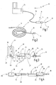
Figur 1 eine erfindungsgemäße Injektionsvorrichtung, in schematisierter Gesamtansicht, -
Figur 2 einen Teil einer alternativen Ausführungsform einer erfindungsgemäßen Injektionsvorrichtung, -
Figur 3 eine Fluidliefereinrichtung einer Injektionsvorrichtung, in einer ersten Ausführungsform, und -
Figur 4 bis 7 Fluidliefereinrichtungen für Injektionsvorrichtungen in abgewandelten Ausführungsformen. - Die in
Figur 1 veranschaulichte Injektionsvorrichtung 10 umfasst einen Fluidapplikator 11 und eine Fluidliefereinrichtung 12 zur Speisung des Fluidapplikators 11 mit einem Fluid. Das Fluid ist vorzugsweise eine physiologische Kochsalzlösung (NaCl-Lösung), die von dem Fluidapplikator 11 in einer geeigneten Strahlform ausgestoßen wird. Vorzugsweise wir ein scharfer laminarer, nadelartiger Strahl bevorzugt. Es können jedoch auch Anwendungsfälle vorgesehen werden, bei denen eine andere Strahlform gewünscht und realisiert wird. - Der Fluidapplikator 11 kann, wie in
Figur 1 schematisch veranschaulicht, zur offenchirurgischen Applikation vorgesehen sein und entsprechend einen Handgriff 13 und einen sich von diesem weg erstreckenden Düsenschaft 14 aufweisen. An dem Handgriff 13 kann ein Betätigungsorgan, bspw. in Gestalt einer Taste 15, vorgesehen sein, über die ein die Speisung des Düsenschafts 14 freigebendes oder sperrendes Ventil oder auch ein Regulierventil betätigbar ist. An dem distalen Ende des Düsenschafts 14 kann eine hier durch eine Schutzkappe 16 verschlossene Fluidaustrittsöffnung 17 angebracht sein, die einen Fluidstrahl der gewünschten Form austreten lassen kann. Die Fluidaustrittsöffnung 17 wird vorzugsweise durch eine Düse gebildet. Zu dem Fluidapplikator 11 gehört ferner eine Fluidleitung 18, die den Fluidapplikator 11 mit der Fluidliefereinrichtung 12 verbindet. Die Fluidleitung 18 führt das Fluid durch den Handgriff 13 hindurch letztendlich zu dem Düsenschaft 14 und seiner Düse. - Während
Figur 1 einen Fluidapplikator 11 zur offenchirurgischen Anwendung veranschaulicht, ist inFigur 2 ein Fluidapplikator 11 zur endoskopischen Anwendung veranschaulicht. Er umfasst im Wesentlichen die Fluidleitung 18, die hier als dünner flexibler Kunststoffschlauch ausgebildet ist, der durch ein Lumen eines Endoskops geschoben werden kann. An seinem distalen Ende 19 ist die Fluidaustrittsöffnung 17 angeordnet. Falls erforderlich kann die Austrittsöffnung durch eine Düse festgelegt sein. - Die Fluidliefereinrichtung 12 dient zur Versorgung des Fluidapplikators 11 mit unter einem im Wesentlichen konstanten Druck stehenden Fluid. Sowohl der Fluidapplikator 11 nach
Figur 1 wie auch der Fluidapplikator 11 nachFigur 2 kann von jeder der nachstehend beschriebenen Fluidliefereinrichtungen 12 mit Fluid versorgt werden. - Wie
Figur 3 zeigt, weist die Fluidliefereinrichtung 12 eine Vorratskammer 20 auf, die vollständig mit einem geeigneten Fluid 21 gefüllt ist. Die Vorratskammer 20 weist einen Ausgang 22 auf, an dem über ein Ventil 23 die Fluidleitung 18 angeschlossen ist. Das Ventil 23 kann ein schaltendes Ventil sein, das nur die beiden Stellungen "offen" und "geschlossen" einnehmen kann. Alternativ kann es sich um ein Drosselventil handeln, mit dem verschiedene Durchflusswiderstände und somit verschiedene Durchflussmengen einstellbar sind. Das Ventil kann ein Bedienorgan bzw. Betätigungsorgang 24 aufweisen, das an einem Gehäuse der Fluidliefereinrichtung 12 angebracht ist. - Die Vorratskammer 20 wird durch ein Aufnahmeraum, der bspw. die Form eines Zylinders aufweist, gebildet, der an einer Seite durch einen beweglichen Kolben 25 verschlossen ist. Der Kolben schließt die Vorratskammer 20 mit einer Wandfläche 26 ab, die bezüglich des übrigen Zylinders beweglich ist, indem der Kolben 25 gegen den Zylinder abgedichtet verschiebbar ist.
- Der Kolben 25 ist über ein Kraftübertragungsmittel, wie bspw. einen Zapfen, einen Stößel, eine Stange 27 oder dergleichen, mit einer Antriebseinrichtung 28 verbunden, die einen Energiespeicher 29 enthält. Die Antriebseinrichtung 28 umfasst im vorliegenden Ausführungsbeispiel außerdem eine Expansionskammer 30, die wenigstens eine bewegliche Wandfläche 31 hat. Das Verhältnis der Wandflächen 26, 31 zueinander ist vorzugsweise verschieden von Eins. Die bewegliche Wandfläche 31 kann durch die Stirnfläche eines in einem Zylinder 32 abgedichtet verschiebbar gelagerten Kolben 33 gebildet sein. Dieser ist über die Stange 27 oder ein sonstiges Kraftübertragungsmittel mit dem Kolben 25 verbunden. Die Stange 27 erstreckt sich durch einen Zwischenraum 34, der ganz oder teilweise von dem Gehäuse umschlossen ist, das die Vorratskammer 20 und die Expansionskammer 30 umschließt. Der Zwischenraum 34 ist vorzugsweise zur Atmosphäre belüftet, wozu mindestens eine Belüftungsöffnung 35 vorgesehen ist.
- Der Energiespeicher 29 bildet eine Druckquelle 36, beispielsweise in Gestalt einer CO2-Kapsel 37. Diese wird durch einen druckfesten Behälter gebildet, der an einem halsartigen Ende 38 mit einer Versiegelung 39 versehen ist. Die Versiegelung 39 kann zur Freisetzung des in der Druckquelle bzw. dem Druckbehälter 36 vorhandenen Gases mittels einer Aufstechnadel 40 durchstochen werden, die Teil einer Behälteraufnahme ist. Die Behälteraufnahme weist Dichtmittel auf, um den Druckbehälter 36 an seinem Hals bzw. Ende 38 abgedichtet aufzunehmen. Die Aufstechnadel 40 durchsticht die Versiegelung 39, wodurch das somit freigesetzte unter Druck stehende Gas über einen Kanal 41 oder auch unmittelbar (
Fig. 4 ) in die Expansionskammer 30 geleitet werden kann. - Die insoweit beschriebene Injektionsvorrichtung 10 arbeitet wie folgt:
- Es wird davon ausgegangen, dass die Fluidliefereinrichtung 12 mit gefüllter Vorratskammer 20 bereitgestellt wird. Die Kolben 25, 33 befinden sich somit in
Figur 3 in linker Position. Das Ventil 23 ist geschlossen und die Fluidleitung 18 zunächst leer. - Zur Aktivierung wird der Druckbehälter 36 in seine Aufnahme eingesetzt, wobei die Versiegelung 39 durchstoßen wird. Alternativ wird ein bereits in der Aufnahme vorhandener vorinstallierter Druckbehälter mittels eines geeigneten Mechanismus angestochen, indem er gegen die Aufstechnadel 40 bewegt oder indem die Aufstechnadel bewegt wird. Der Mechanismus kann z.B. ein handhebelbetätigter Exzenter sein, an dem sich das dem Hals gegenüberliegende Ende 38 des Druckbehälters 36 abstützt. Andere Mechanismen, wie Kniehebelanordnungen oder dergleichen können vorgesehen sein.
- Handelt es sich bei dem Druckbehälter 36 um eine handelsübliche CO2-Kapsel mit einer Füllung von z.B. 12g CO2, wirkt unmittelbar ein Druck von 55 bar bis 60 bar auf die Wandfläche 31. Die entsprechende in
Figur 3 nach rechts gerichtete Kraft wird über die Stange 27 auf den Kolben 25 übertragen. Infolge des Durchmesserverhältnisses der Kolben 33, 25 zueinander, kann ein gewünschter Fluiddruck von beispielsweise 30 bar hervorgerufen werden. In diesem Fall hat die Wandfläche 26 den doppelten Flächeninhalt wie die Wandfläche 31. - Der Anwender betätigt nun das Ventil 23, um es zu öffnen und die Fluidleitung 18 bis zur Fluidaustrittsöffnung 17 mit Fluid zu füllen. Wenn eine Schutzkappe 16 vorhanden ist, nimmt er diese zuvor ab. Die Injektionsvorrichtung 10 ist nun betriebsbereit. Je nach Bauform des Fluidapplikators 11 kann diese durch entsprechende Handhabung des Handgriffs 13 und bedarfsweise Betätigung der Taste 15 (falls vorhanden) benutzt werden. Tritt aus der Fluidaustrittsöffnung 17 ein scharfer Fluidstrahl aus, kann dieser in ein biologisches Gewebe eindringen und dort zum Beispiel zum Unterspritzen der Mucosa genutzt werden. Andere Anwendungen zum Einspritzen in und Unterspritzen von Geweben sind möglich. Der Anwender kann bspw. mit dem austretenden Strahl auch Organgewebe auflösen. Dazu kann die Fluidaustrittsöffnung 17 auch so gestaltet werden, dass anderen Strahlformen bspw. Fächerstrahlen oder dergleichen erzeugt werden.
- Bei Anwendung des Fluidapplikators 11 nach
Figur 2 wird dieser zum Beispiel durch ein Endoskop in eine Körperhöhle, bspw. den Gastrointestinaltrakt, geführt, um dort mit dem aus der Fluidaustrittsöffnung 17 austretendem Fluidstrahl Unterspritzungen bspw. der Mucosa vorzunehmen. - Der Fluidvorrat kann auf 200 ml bis 300 ml bemessen sein. Ein solcher Fluidvorrat kann mit einer einzigen CO2-Kapsel 37 (z.B. 12 g) mit nahezu konstantem Druck von 30 bar ausgestoßen werden. Somit ergeben sich für den Anwender verlässliche und konstante Operationsbedingungen. Die Injektionsvorrichtung 10 ist dabei insgesamt sehr einfach zu handhaben und unabhängig von Fremdenergie oder von der Geschicklichkeit eines Assistenten einsetzbar.
- Es sind Abwandlungen möglich, die nachfolgend exemplarisch erläutert werden und die insbesondere die Fluidliefereinrichtung 12 betreffen. Beispielsweise kann der Druckbehälter 36 sowohl wie in
Figur 3 dargestellt, in einem Winkel zu der Bewegungsrichtung des Kolbens 33 wie auch koaxial zu diesem angeordnet sein, wieFigur 4 veranschaulicht. Damit kann eine kompakte schlanke Bauform erreicht werden. Außerdem ist es sowohl möglich, die Injektionsvorrichtung 10 insgesamt oder lediglich die Fluidliefereinrichtung 12 als Einmalgerät oder als mehrfach verwendbare Vorrichtung auszubilden.Figur 4 veranschaulicht dies an einem Beispiel, bei dem die Vorratskammer 20 und ihr Kolben 25 als gesondert handhabbare Baugruppe nach Art einer druckfesten Spritze ausgebildet sind. Diese wird in eine Fassung des Gehäuses eingelegt, wobei die Stange 27 gegen den Kolben 25 drückt. Sobald der Druckbehälter 36, z.B. eine CO2-Kapsel 37 in ihre entsprechende Fassung eingesetzt ist, ist die Kammer 30 druckbeaufschlagt, womit die Stange 27 mit im Wesentlichen konstanter Kraft gegen den Kolben 25 drückt. Über die an den Ausgang 22 angeschlossene Fluidleitung 18 kann nun wie vorbeschrieben gearbeitet werden. Das Ventil 23 kann in dem Handgriff 13 oder an anderer Stelle der Fluidleitung 18 angeordnet sein. - Ist die Vorratskammer 20 leer, kann sie durch eine sterile, volle ersetzt werden. Ebenso kann die CO2-Kapsel 37 entsorgt werden, womit die Expansionskammer 30 zunächst drucklos wird. Über ein geeignetes Mittel 50 kann der Kolben 25 in seine linke Ruheposition zurückgeschoben werden. In diesem Zustand können eine neue Vorratskammer 20, d.h. eine neue Spritze und eine neue CO2-Kapsel 37 in das Gehäuse eingesetzt werden, womit die Fluidliefereinrichtung 12 wiederum betriebsbereit ist. Bei solchen wiederverwendbaren Vorrichtungen kann an die Expansionskammer 30 auch ein Restdruckentleerungsventil angeschlossen sein, um vorhandenes restliches Treibfluid gefahrlos ablassen zu können.
- Alternativ zur Nutzung von zylindrischen Kammern für die Expansionskammer 30 und die Vorratskammer 20 mit entsprechenden Kolben 25, 33, kann gemäß
Figur 5 die Vorratskammer 20 in der Expansionskammer 30 angeordnet werden. Die Vorratskammer 20 kann bspw. durch einen Beutel oder einen sonstigen komprimierbaren Behälter gebildet werden, der an den Ausgang 22 angeschlossen ist. Die Innenfläche des Beutels bildet die erste bewegliche Wandfläche 26. Die Außenseite des Beutels bildet die zweie bewegliche Wandfläche 31. Wiederum dient ein Druckbehälter 36 als Energiespeicher 29 zur Druckbeaufschlagung der Expansionskammer 30. Sobald mit der Aufstechnadel 40 die an dem Behälterhals des Druckbehälters 36 vorgesehene Versiegelung 39 durchstochen ist, steht die Expansionskammer 30 unter Druck. Dieser wirkt auf die Wandfläche 31 und somit in gleicher Größe über die Wandfläche 26 auf den Fluidvorrat in dem Beutel. Über das Ventil 23 kann dann unter Druck stehendes Fluid gezielt freigegeben werden, um den Fluidapplikator 11 zu speisen. - Der den Fluidvorrat enthaltende Beutel kann als Einmalprodukt ausgebildet sein, während das die Kammer 30 umschließende und den Druckbehälter 36 aufnehmende Gehäuse zur mehrfachen Verwendung eingerichtet sein kann. Alternativ können auch diese Teile als Einmalprodukt ausgebildet sein.
- Vorzugsweise ist an dem Anschluss 22 eine in das Innere der Vorratskammer 20 führende Auslassöffnung 42 vorgesehen, die eine Flussrestriktion darstellt und beispielsweise lediglich einen Durchmesser von einem Millimeter oder weniger aufweist. Diese Restriktion sorgt dafür, dass ein vollständig entleerter Beutel mit seiner flexiblen Wand die entsprechende Auslassöffnung 42 verschließt. Die Querschnittsfläche der Auslassöffnung 42 ist dabei vorzugsweise so gering, dass die auf der Auslassöffnung 42 liegende Beutelwand unter dem Druck der CO2-Kapsel 37 mit Sicherheit nicht reißt. Beispielsweise ist der Durchmesser der Auslassöffnung 42 zu diesem Zweck geringer als die Wandstärke des die Vorratskammer 20 umschließenden Beutels.
- Weitere Abwandlungen sind möglich.
Figur 6 veranschaulicht dazu eine Fluidliefereinrichtung 12 mit einem Energiespeicher 29 in Gestalt eines Federspeichers. Es ist dazu bspw. eine vorgespannte Druckfeder 43 vorhanden, die sich mit einem Ende an den Kolben 25 und mit ihrem anderen Ende an eine Gehäusewand abstützt. Damit ist das Fluid 21 über den Kolben 25 unter Druck gesetzt. - Es ist möglich, den Kolben 25 über ein Zugmittel bspw. eine Zugstange 44 und eine Arretiereinrichtung 45, in dem Gehäuse zu arretieren. In diesem Fall nimmt die Zugstange 44 die Kraft der Druckfeder 43 auf. Wird die Arretiereinrichtung 45 bspw. durch Abreißen oder Entfernen eines Blockierstifts gelöst, wirkt die Federkraft auf den Kolben und setzt das Fluid 21 unter Druck. Damit kann das Fluid 21 über das Ventil 23 freigegeben werden und über die Leitung 18 kontrolliert ausströmen. Die Fluidliefereinrichtung 12 kann als wiederbefüllbares Produkt oder als Einwegprodukt ausgebildet sein.
- Letzteres gilt auch für die Ausführungsform nach
Figur 7 . Danach ist als Energiespeicher 29 eine elektrische Batterie 46 oder ein Akku, ein Superkondensator oder dergleichen vorgesehen, der zur Speisung eines Motors 47 dient. Der Motor 47 betätigt über ein Getriebe den Kolben 25. Das Getriebe ist vorzugsweise ein Untersetzungsgetriebe, das z.B. über ein Spindel-Gewinde-Trieb 48 den Kolben 25 bewegt. Ein Schalter 49 dient zum Aktivieren des Motors 47. Vorzugsweise sind der Motor 47 und seine speisende Einrichtung so aufeinander abgestimmt, dass der Motor 47 über einen langen Zeitraum (mehrere Minuten) unter Storm gesetzt werden kann. Vorzugsweise ist der Motor 47 dabei als Torquemotor ausgebildet, so dass er bei Drehzahl Null als Drehmomentquelle betrieben werden kann. Dabei gibt er unabhängig von seiner Drehzahl ein im Wesentlichen konstantes Drehmoment ab, das über den Spindel-Gewinde-Trieb 48 eine konstante, auf den Kolben 25 einwirkende Kraft ergibt. Diese ist so bemessen, dass sich in der Vorratskammer 20 der gewünschte Druck von z.B. 30 bar oder 40 bar einstellt. Der Energievorrat der Batterie 46 ist so groß, dass der Motor 47 mindestens den gesamten Vorrat der Vorratskammer 20 einmal ausspritzen kann. Auch dieses Produkt kann als Einwegprodukt oder als wiederbefüllbares Produkt ausgebildet sein. Die Vorratskammer 20 und/oder die Batterie 36 können auswechselbar ausgebildet und angeordnet sein. - Die erfindungsgemäße Injektionsvorrichtung 10 weist einen Fluidapplikator 11 auf, der von einer Fluidliefereinrichtung 12 gespeist wird, die einen Energiespeicher 29 enthält. Vorzugsweise ist dieser als Druckbehälter 36 ausgebildet. Der von diesem Druckbehälter 36 ausgehende Gasdruck wirkt auf einen mit der Flüssigkeit bzw. dem Fluid (z.B. isotonischer NaCL-Lösung) vorgefüllten Behälter entweder direkt (
Figur 5 ) oder indirekt (Figur 3, 4 ). Die auszustoßende Flüssigkeit wird somit unter konstanten Druck gesetzt. Mit einem Ventil 23 kann der Anwender den Ausstoß der gewünschten Flüssigkeitsmenge mit konstanter Intensität veranlassen. Das Sperrventil 23 kann auch ein Drosselventil sein, womit die Intensität des Effekts durch den Anwender variiert werden kann. Die Erfindung bietet die Basis, eine sehr kostengünstig herstellbare immer verfügbare Injektionsvorrichtung zu realisieren. Der Anwender muss lediglich das System entsichern, z.B. indem er den Druckbehälter 36 ansticht, um dann über die Fluidleitung 18, d.h. den Fluidapplikator 11, unmittelbar Flüssigkeit definiert bzw. dosiert injizieren zu können. Die Handhabung sowohl des Entsicherns als auch die Betätigung des Sperr- oder Drosselventils 23 ist einfach und intuitiv möglich. Es ist auch möglich, die gesamte Injektionsvorrichtung 10 als Einmalsystem auszubilden, und dem Fluidapplikator 11 bis zu seiner Fluidaustrittsöffnung hin vorzufüllen. Ein steriler Verschluss am distalen Ende des Fluidapplikators 12 kann durch eine Schutzkappe 16 gebildet werden. -
- 10
- Injektionsvorrichtung
- 11
- Fluidapplikator
- 12
- Fluidliefereinrichtung
- 13
- Handgriff
- 14
- Düsenschaft
- 15
- Taste
- 16
- Schutzkappe
- 17
- Fluidaustrittsöffnung
- 18
- Fluidleitung
- 19
- distales Ende
- 20
- Vorratskammer
- 21
- Fluid
- 22
- Ausgang
- 23
- Ventil
- 24
- Betätigungsorgan
- 25
- Kolben
- 26
- erste bewegliche Wandfläche
- 27
- Stange
- 28
- Antriebseinrichtung
- 29
- Energiespeicher
- 30
- Expansionskammer
- 31
- zweite bewegliche Wandfläche
- 32
- Zylinder
- 33
- Kolben
- 34
- Zwischenraum
- 35
- Belüftungsöffnung
- 36
- Druckbehälter, Druckquelle
- 37
- CO2-Kapsel
- 38
- Ende
- 39
- Versiegelung
- 40
- Aufstechnadel
- 41
- Kanal
- 42
- Auslassöffnung
- 43
- Druckfeder
- 44
- Zugstange
- 45
- Arretiereinrichtung
- 46
- Batterie, Akkumulator
- 47
- Motor
- 48
- Spindel-Gewinde-Trieb
- 49
- Schalter
- 50
- Mittel zur Handhabung
Claims (15)
- Injektionsvorrichtung (10) mit:einem Fluidapplikator (11), der eine Fluidaustrittsöffnung (17) zur nadellosen Injektion eines Fluids in ein biologisches Gewebe und eine zu der Fluidaustrittsöffnung (17) führende Fluidleitung (18) aufweist,einer Fluidliefereinrichtung (12), die eine Antriebseinrichtung (28) und eine Vorratskammer (20) aufweist oder mit einer solchen verbindbar ist,wobei die Vorratskammer (20) wenigstens eine erste bewegliche Wandfläche (26) aufweist, die mit einer von der Antriebseinrichtung (28) erzeugten Kraft beaufschlagbar ist,dadurch gekennzeichnet, dassdie Antriebseinrichtung (28) einen Energiespeicher (29) aufweist.
- Injektionsvorrichtung nach Anspruch 1, dadurch gekennzeichnet, dass der Energiespeicher (29) eine gespannte Feder (43) aufweist, die sich mit einem Ende an einem Kolben (25), der die ersten beweglichen Wandfläche (26) aufweist, und mit ihrem anderen Ende an einem Gehäuse abstützt, das mit der Vorratskammer (20) verbunden ist.
- Injektionsvorrichtung nach Anspruch 2, dadurch gekennzeichnet, dass der Feder (43) eine lösbare Arretierung (45) zugeordnet ist.
- Injektionsvorrichtung nach Anspruch 1, dadurch gekennzeichnet, dass der Energiespeicher (29) eine elektrische Batterie (46) ist, die über einen Schalter (49) mit einem Elektromotor (47) verbunden ist, der direkt oder über ein Getriebe (48) mit der beweglichen Wandfläche (26) der Vorratskammer (20) verbunden ist.
- Injektionsvorrichtung nach Anspruch 1, dadurch gekennzeichnet, dass die Antriebseinrichtung (28) ein Energiespeicher (29) und eine Expansionskammer (30) aufweist, die eine zweite bewegliche Wandfläche (31) aufweist, die von dem Energiespeicher (29) mit einem Druckfluid beaufschlagbar ist.
- Injektionsvorrichtung nach Anspruch 5, dadurch gekennzeichnet, dass der Energiespeicher (29) einen druckspeichernden Druckbehälter (36) aufweist.
- Injektionsvorrichtung nach einem Ansprüche 6, dadurch gekennzeichnet, dass der Druckbehälter (36) eine CO2-Kapsel (37) mit einer gasdichten Versiegelung (39) ist.
- Injektionsvorrichtung nach Anspruch 7, dadurch gekennzeichnet, dass dem Energiespeicher (29) eine Wechselaufnahme für den Druckbehälter (36) und eine Durchstecheinrichtung (40) für die Versiegelung (39) zugeordnet ist.
- Injektionsvorrichtung nach einem der Ansprüche 5 bis 8, dadurch gekennzeichnet, dass die erste bewegliche Wandfläche (26) und die zweite bewegliche Wandfläche (31) unterschiedliche Flächeninhalte aufweisen.
- Injektionsvorrichtung nach einem Ansprüche 5 bis 9, dadurch gekennzeichnet, dass zwischen der ersten Wandfläche (26) und der zweiten Wandfläche (31) ein belüfteter Raum (34) angeordnet ist.
- Injektionsvorrichtung nach einem der vorigen Ansprüche, dadurch gekennzeichnet, dass zwischen der Vorratskammer (20) und der Fluidaustrittsöffnung (17) ein Ventil (23) angeordnet ist.
- Injektionsvorrichtung nach Anspruch 11, dadurch gekennzeichnet, dass das Ventil (23) ein Sperrventil ist.
- Injektionsvorrichtung nach Anspruch 11, dadurch gekennzeichnet, dass das Ventil (23) ein Drosselventil ist.
- Injektionsvorrichtung nach einem der vorigen Ansprüche, dadurch gekennzeichnet, dass die Fluidaustrittsöffnung (17) mit einer Schutzkappe (16) versehen ist.
- Verfahren zur Erzeugung eines in ein biologisches Gewebe eindringungsfähigen Fluidstrahls, mit folgenden Schritten:Bereitstellung eines Energiespeichers (29) und Erzeugung einer Kraft aus in dem Energiespeicher gespeicherter Energie,Bereitstellung einer mit einem Fluid gefüllten Vorratskammer (20) mit wenigstens einer ersten beweglichen Wandfläche (26) und Beaufschlagung derselben mit der von der Antriebseinrichtung (28) erzeugten Kraft,
Zuleitung des Fluids zu einem Fluidapplikator (11), der eine Fluidaustrittsöffnung (17) aufweist, und Austretenlassen des Fluids aus der Fluidaustrittsöffnung (17) als Strahl.
Priority Applications (8)
| Application Number | Priority Date | Filing Date | Title |
|---|---|---|---|
| PL12192953.3T PL2732770T3 (pl) | 2012-11-16 | 2012-11-16 | Bezigłowe urządzenie do iniekcji |
| EP12192953.3A EP2732770B1 (de) | 2012-11-16 | 2012-11-16 | Nadellose Injektionsvorrichtung |
| US14/079,114 US9044545B2 (en) | 2012-11-16 | 2013-11-13 | Needleless injection device |
| KR1020130137790A KR101704106B1 (ko) | 2012-11-16 | 2013-11-13 | 무바늘 주입 장치 |
| BR102013029470-5A BR102013029470B1 (pt) | 2012-11-16 | 2013-11-14 | Dispositivo de injeção |
| CN201310571096.2A CN103816588B (zh) | 2012-11-16 | 2013-11-15 | 无针注射装置 |
| RU2013150912A RU2650584C2 (ru) | 2012-11-16 | 2013-11-15 | Инъектор для безыгольных инъекций |
| JP2013236400A JP5856132B2 (ja) | 2012-11-16 | 2013-11-15 | 無針注射器具 |
Applications Claiming Priority (1)
| Application Number | Priority Date | Filing Date | Title |
|---|---|---|---|
| EP12192953.3A EP2732770B1 (de) | 2012-11-16 | 2012-11-16 | Nadellose Injektionsvorrichtung |
Publications (2)
| Publication Number | Publication Date |
|---|---|
| EP2732770A1 true EP2732770A1 (de) | 2014-05-21 |
| EP2732770B1 EP2732770B1 (de) | 2016-08-24 |
Family
ID=47278112
Family Applications (1)
| Application Number | Title | Priority Date | Filing Date |
|---|---|---|---|
| EP12192953.3A Active EP2732770B1 (de) | 2012-11-16 | 2012-11-16 | Nadellose Injektionsvorrichtung |
Country Status (8)
| Country | Link |
|---|---|
| US (1) | US9044545B2 (de) |
| EP (1) | EP2732770B1 (de) |
| JP (1) | JP5856132B2 (de) |
| KR (1) | KR101704106B1 (de) |
| CN (1) | CN103816588B (de) |
| BR (1) | BR102013029470B1 (de) |
| PL (1) | PL2732770T3 (de) |
| RU (1) | RU2650584C2 (de) |
Families Citing this family (15)
| Publication number | Priority date | Publication date | Assignee | Title |
|---|---|---|---|---|
| WO2015009673A2 (en) * | 2013-07-17 | 2015-01-22 | Bayer Medical Care Inc. | Cartridge-based in-bore infuser |
| JP2015058240A (ja) * | 2013-09-20 | 2015-03-30 | セイコーエプソン株式会社 | 医療機器システム、液体供給装置 |
| US10258502B2 (en) | 2014-09-18 | 2019-04-16 | Orbit Biomedical Limited | Therapeutic agent delivery device |
| US20180311439A1 (en) * | 2015-11-27 | 2018-11-01 | Sanofi-Aventis Deutschland Gmbh | An injection device with an expandable cavity |
| CN105709311A (zh) * | 2016-01-18 | 2016-06-29 | 华南农业大学 | 一种基于压电转换的无针注射器及其使用方法 |
| WO2018038118A1 (ja) * | 2016-08-23 | 2018-03-01 | 株式会社ダイセル | 投与装置 |
| JP7127022B2 (ja) * | 2016-11-01 | 2022-08-29 | サノフィ-アベンティス・ドイチュラント・ゲゼルシャフト・ミット・ベシュレンクテル・ハフツング | 容積測定装置 |
| CN106668992B (zh) * | 2016-11-28 | 2019-07-12 | 合肥讯创信息科技有限公司 | 增压无针注射装置 |
| CN107126599A (zh) * | 2017-06-19 | 2017-09-05 | 上海完形健康管理咨询有限公司 | 一种无针低压渗透水剥离祛皱装置 |
| PL3628356T3 (pl) * | 2018-09-26 | 2022-05-02 | Erbe Elektromedizin Gmbh | Instrument medyczny i urządzenie wytwarzające |
| GB201905015D0 (en) * | 2019-04-09 | 2019-05-22 | Alchemie Tech Ltd | Improvements in or relating to industrial fluid dispensing |
| NL2024158B1 (en) * | 2019-11-05 | 2021-07-20 | Univ Delft Tech | Waterjet cutting system |
| KR102463473B1 (ko) * | 2020-10-26 | 2022-11-04 | 미라클스코프(주) | 약물주입단자를 구비한 무침주사기 |
| AT526629B1 (de) * | 2022-10-19 | 2024-09-15 | Juergen Stockmar Prof Dipl Ing Dr H C | Applikator, Gerät und Verfahren zum nadellosen Einspritzen eines zu injizierenden Wirkmediums |
| CN117045903A (zh) * | 2023-09-22 | 2023-11-14 | 杭州电子科技大学 | 一种空心杯电机驱动的连续无针注射装置 |
Citations (4)
| Publication number | Priority date | Publication date | Assignee | Title |
|---|---|---|---|---|
| US20020143323A1 (en) * | 1997-05-23 | 2002-10-03 | Johnston Mark H. | Method and apparatus for cryogenic spray ablation of gastrointestinal mucosa |
| DE69533811T2 (de) | 1994-06-17 | 2005-12-15 | Safe-T-Ltd., Lonan | Hohlnadelapplikatoren für arzneien und ähnlichem |
| US20060149193A1 (en) * | 2005-01-05 | 2006-07-06 | Biomec, Inc. | High pressure liquid jet ablation of tissue and apparatus |
| US20090157114A1 (en) | 2005-04-11 | 2009-06-18 | Klaus Fischer | Method for selectively elevating and separating tissue layers and surgical instrument for performing the method |
Family Cites Families (21)
| Publication number | Priority date | Publication date | Assignee | Title |
|---|---|---|---|---|
| SU480420A1 (ru) * | 1974-07-30 | 1975-08-15 | Центральный научно-исследовательский институт стоматологии | Безыгольный инъектор |
| US4342310A (en) * | 1980-07-08 | 1982-08-03 | Istvan Lindmayer | Hydro-pneumatic jet injector |
| US5312335A (en) * | 1989-11-09 | 1994-05-17 | Bioject Inc. | Needleless hypodermic injection device |
| US5322511A (en) * | 1992-04-21 | 1994-06-21 | Sterling Winthrop Inc. | Portable hand-held power injector |
| ATE197904T1 (de) * | 1993-07-31 | 2000-12-15 | Weston Medical Ltd | Nadelloser injektor |
| US5398851A (en) * | 1993-08-06 | 1995-03-21 | River Medical, Inc. | Liquid delivery device |
| US5700245A (en) * | 1995-07-13 | 1997-12-23 | Winfield Medical | Apparatus for the generation of gas pressure for controlled fluid delivery |
| US6096002A (en) | 1998-11-18 | 2000-08-01 | Bioject, Inc. | NGAS powered self-resetting needle-less hypodermic jet injection apparatus and method |
| US6783509B1 (en) * | 1998-11-18 | 2004-08-31 | Bioject Inc. | Single-use needle-less hypodermic jet injection apparatus and method |
| JP3555509B2 (ja) | 1999-06-29 | 2004-08-18 | 株式会社村田製作所 | スピーカ |
| CA2331030A1 (en) | 2000-02-16 | 2001-08-16 | Roche Diagnostics Gmbh | Hypodermic needleless injection system |
| CN1227042C (zh) * | 2000-07-22 | 2005-11-16 | 金容年 | 液体供给设备 |
| MXPA03009385A (es) * | 2001-04-13 | 2004-11-12 | Penjet Corp | Inyector modular libre de aguja, presurizado con gas. |
| KR100507593B1 (ko) | 2002-02-08 | 2005-08-10 | 주식회사 이화양행 | 액체공급장치 |
| US7803141B2 (en) * | 2003-08-12 | 2010-09-28 | Boston Scientific Scimed, Inc. | Device and method for direct delivery of a therapeutic using non-newtonian fluids |
| EP1570875A1 (de) * | 2004-03-04 | 2005-09-07 | Roche Diagnostics GmbH | Nadelfreier Strahlinjektor mit pyrotechnischem Antrieb mit billigen Bauteilen und Herstellung |
| US7717874B2 (en) * | 2004-05-28 | 2010-05-18 | Bioject, Inc. | Needle-free injection system |
| US7686788B2 (en) * | 2005-03-03 | 2010-03-30 | Boston Scientific Scimed, Inc. | Catheter having a distal drug delivery unit and method of using same |
| US8591457B2 (en) * | 2005-08-10 | 2013-11-26 | Alza Corporation | Method for making a needle-free jet injection drug delivery device |
| CA2739968A1 (en) * | 2008-10-10 | 2010-04-15 | Deka Products Limited Partnership | Infusion pump assembly |
| JP5856621B2 (ja) * | 2010-09-15 | 2016-02-10 | ゾゲニクス インコーポレーティッド | 無針注射器および注射性能を最適化する同注射器の設計パラメータ |
-
2012
- 2012-11-16 EP EP12192953.3A patent/EP2732770B1/de active Active
- 2012-11-16 PL PL12192953.3T patent/PL2732770T3/pl unknown
-
2013
- 2013-11-13 KR KR1020130137790A patent/KR101704106B1/ko active Active
- 2013-11-13 US US14/079,114 patent/US9044545B2/en active Active
- 2013-11-14 BR BR102013029470-5A patent/BR102013029470B1/pt active IP Right Grant
- 2013-11-15 CN CN201310571096.2A patent/CN103816588B/zh active Active
- 2013-11-15 RU RU2013150912A patent/RU2650584C2/ru active
- 2013-11-15 JP JP2013236400A patent/JP5856132B2/ja active Active
Patent Citations (4)
| Publication number | Priority date | Publication date | Assignee | Title |
|---|---|---|---|---|
| DE69533811T2 (de) | 1994-06-17 | 2005-12-15 | Safe-T-Ltd., Lonan | Hohlnadelapplikatoren für arzneien und ähnlichem |
| US20020143323A1 (en) * | 1997-05-23 | 2002-10-03 | Johnston Mark H. | Method and apparatus for cryogenic spray ablation of gastrointestinal mucosa |
| US20060149193A1 (en) * | 2005-01-05 | 2006-07-06 | Biomec, Inc. | High pressure liquid jet ablation of tissue and apparatus |
| US20090157114A1 (en) | 2005-04-11 | 2009-06-18 | Klaus Fischer | Method for selectively elevating and separating tissue layers and surgical instrument for performing the method |
Also Published As
| Publication number | Publication date |
|---|---|
| RU2650584C2 (ru) | 2018-04-16 |
| CN103816588B (zh) | 2017-04-05 |
| US20140142536A1 (en) | 2014-05-22 |
| JP2014100563A (ja) | 2014-06-05 |
| KR20140063446A (ko) | 2014-05-27 |
| US9044545B2 (en) | 2015-06-02 |
| BR102013029470B1 (pt) | 2021-09-08 |
| JP5856132B2 (ja) | 2016-02-09 |
| CN103816588A (zh) | 2014-05-28 |
| KR101704106B1 (ko) | 2017-02-07 |
| EP2732770B1 (de) | 2016-08-24 |
| PL2732770T3 (pl) | 2016-12-30 |
| RU2013150912A (ru) | 2015-05-20 |
| BR102013029470A2 (pt) | 2014-10-07 |
Similar Documents
| Publication | Publication Date | Title |
|---|---|---|
| EP2732770B1 (de) | Nadellose Injektionsvorrichtung | |
| DE60111967T2 (de) | Nadelloses Subkutaninjektionssystem | |
| EP2957337B1 (de) | Vakuummischsystem und verfahren zum mischen von polymethylmethacrylat-knochenzement | |
| DE69426390T2 (de) | Nadelloser injektor | |
| AT514484B1 (de) | Aktivator für einen Autoinjektor | |
| EP2448617A1 (de) | Aufsatz für eine standardspritzenvorrichtung sowie injektionsgerät zur nadellosen injektion | |
| DE60124013T2 (de) | Injektionsvorrichtung mit wiederverwendbarem druckerzeugungsmittel | |
| DE10351594A1 (de) | Vorrichtung für die Verabreichung eines injizierbaren Produkts | |
| DE102015111320B4 (de) | Vakuummischsystem und Verfahren zum Mischen von Polymethylmethacrylat-Knochenzement | |
| EP3100694B1 (de) | Vorrichtung und verfahren zum mischen und lagern von polymethylmethacrylat-knochenzement | |
| WO2003015853A1 (de) | Ampulle für eine injektionseinrichtung | |
| EP3544656A1 (de) | Vorrichtung zur abgabe einer substanz | |
| WO2006114012A1 (de) | Vorrichtung zur verabreichung eines fluiden produkts | |
| DE1287743B (de) | ||
| WO2012171898A1 (de) | Transport- und transferbehältnis für ein fluides medium | |
| EP3706834A1 (de) | Verfahren und vorrichtung zum nadellosen injizieren von flüssigkeit in ein substrat | |
| EP3153240B1 (de) | Pasten-applikationsvorrichtung zum mischen einer paste | |
| EP2056901A1 (de) | Injektionseinrichtung | |
| DE2461272A1 (de) | Injektionseinrichtung | |
| DE2740328A1 (de) | Einrichtung zur sauginjektion | |
| DE102014016303A1 (de) | Koppelbarer Stoffbehälter für Kapillarnadeln | |
| EP4134113A1 (de) | Applikator mit dosiereinheit |
Legal Events
| Date | Code | Title | Description |
|---|---|---|---|
| PUAI | Public reference made under article 153(3) epc to a published international application that has entered the european phase |
Free format text: ORIGINAL CODE: 0009012 |
|
| 17P | Request for examination filed |
Effective date: 20121116 |
|
| AK | Designated contracting states |
Kind code of ref document: A1 Designated state(s): AL AT BE BG CH CY CZ DE DK EE ES FI FR GB GR HR HU IE IS IT LI LT LU LV MC MK MT NL NO PL PT RO RS SE SI SK SM TR |
|
| AX | Request for extension of the european patent |
Extension state: BA ME |
|
| 17Q | First examination report despatched |
Effective date: 20150612 |
|
| GRAP | Despatch of communication of intention to grant a patent |
Free format text: ORIGINAL CODE: EPIDOSNIGR1 |
|
| INTG | Intention to grant announced |
Effective date: 20160422 |
|
| GRAS | Grant fee paid |
Free format text: ORIGINAL CODE: EPIDOSNIGR3 |
|
| GRAR | Information related to intention to grant a patent recorded |
Free format text: ORIGINAL CODE: EPIDOSNIGR71 |
|
| GRAA | (expected) grant |
Free format text: ORIGINAL CODE: 0009210 |
|
| AK | Designated contracting states |
Kind code of ref document: B1 Designated state(s): AL AT BE BG CH CY CZ DE DK EE ES FI FR GB GR HR HU IE IS IT LI LT LU LV MC MK MT NL NO PL PT RO RS SE SI SK SM TR |
|
| INTG | Intention to grant announced |
Effective date: 20160719 |
|
| REG | Reference to a national code |
Ref country code: GB Ref legal event code: FG4D Free format text: NOT ENGLISH |
|
| REG | Reference to a national code |
Ref country code: CH Ref legal event code: EP |
|
| REG | Reference to a national code |
Ref country code: AT Ref legal event code: REF Ref document number: 822317 Country of ref document: AT Kind code of ref document: T Effective date: 20160915 |
|
| REG | Reference to a national code |
Ref country code: IE Ref legal event code: FG4D Free format text: LANGUAGE OF EP DOCUMENT: GERMAN |
|
| REG | Reference to a national code |
Ref country code: DE Ref legal event code: R096 Ref document number: 502012008040 Country of ref document: DE |
|
| REG | Reference to a national code |
Ref country code: FR Ref legal event code: PLFP Year of fee payment: 5 |
|
| REG | Reference to a national code |
Ref country code: LT Ref legal event code: MG4D |
|
| REG | Reference to a national code |
Ref country code: NL Ref legal event code: MP Effective date: 20160824 |
|
| RAP2 | Party data changed (patent owner data changed or rights of a patent transferred) |
Owner name: ERBE ELEKTROMEDIZIN GMBH |
|
| PG25 | Lapsed in a contracting state [announced via postgrant information from national office to epo] |
Ref country code: LT Free format text: LAPSE BECAUSE OF FAILURE TO SUBMIT A TRANSLATION OF THE DESCRIPTION OR TO PAY THE FEE WITHIN THE PRESCRIBED TIME-LIMIT Effective date: 20160824 Ref country code: FI Free format text: LAPSE BECAUSE OF FAILURE TO SUBMIT A TRANSLATION OF THE DESCRIPTION OR TO PAY THE FEE WITHIN THE PRESCRIBED TIME-LIMIT Effective date: 20160824 Ref country code: NL Free format text: LAPSE BECAUSE OF FAILURE TO SUBMIT A TRANSLATION OF THE DESCRIPTION OR TO PAY THE FEE WITHIN THE PRESCRIBED TIME-LIMIT Effective date: 20160824 Ref country code: NO Free format text: LAPSE BECAUSE OF FAILURE TO SUBMIT A TRANSLATION OF THE DESCRIPTION OR TO PAY THE FEE WITHIN THE PRESCRIBED TIME-LIMIT Effective date: 20161124 Ref country code: HR Free format text: LAPSE BECAUSE OF FAILURE TO SUBMIT A TRANSLATION OF THE DESCRIPTION OR TO PAY THE FEE WITHIN THE PRESCRIBED TIME-LIMIT Effective date: 20160824 Ref country code: RS Free format text: LAPSE BECAUSE OF FAILURE TO SUBMIT A TRANSLATION OF THE DESCRIPTION OR TO PAY THE FEE WITHIN THE PRESCRIBED TIME-LIMIT Effective date: 20160824 |
|
| PG25 | Lapsed in a contracting state [announced via postgrant information from national office to epo] |
Ref country code: LV Free format text: LAPSE BECAUSE OF FAILURE TO SUBMIT A TRANSLATION OF THE DESCRIPTION OR TO PAY THE FEE WITHIN THE PRESCRIBED TIME-LIMIT Effective date: 20160824 Ref country code: GR Free format text: LAPSE BECAUSE OF FAILURE TO SUBMIT A TRANSLATION OF THE DESCRIPTION OR TO PAY THE FEE WITHIN THE PRESCRIBED TIME-LIMIT Effective date: 20161125 Ref country code: SE Free format text: LAPSE BECAUSE OF FAILURE TO SUBMIT A TRANSLATION OF THE DESCRIPTION OR TO PAY THE FEE WITHIN THE PRESCRIBED TIME-LIMIT Effective date: 20160824 Ref country code: BE Free format text: LAPSE BECAUSE OF NON-PAYMENT OF DUE FEES Effective date: 20161130 Ref country code: ES Free format text: LAPSE BECAUSE OF FAILURE TO SUBMIT A TRANSLATION OF THE DESCRIPTION OR TO PAY THE FEE WITHIN THE PRESCRIBED TIME-LIMIT Effective date: 20160824 Ref country code: PT Free format text: LAPSE BECAUSE OF FAILURE TO SUBMIT A TRANSLATION OF THE DESCRIPTION OR TO PAY THE FEE WITHIN THE PRESCRIBED TIME-LIMIT Effective date: 20161226 |
|
| PG25 | Lapsed in a contracting state [announced via postgrant information from national office to epo] |
Ref country code: RO Free format text: LAPSE BECAUSE OF FAILURE TO SUBMIT A TRANSLATION OF THE DESCRIPTION OR TO PAY THE FEE WITHIN THE PRESCRIBED TIME-LIMIT Effective date: 20160824 Ref country code: EE Free format text: LAPSE BECAUSE OF FAILURE TO SUBMIT A TRANSLATION OF THE DESCRIPTION OR TO PAY THE FEE WITHIN THE PRESCRIBED TIME-LIMIT Effective date: 20160824 |
|
| REG | Reference to a national code |
Ref country code: DE Ref legal event code: R097 Ref document number: 502012008040 Country of ref document: DE |
|
| PG25 | Lapsed in a contracting state [announced via postgrant information from national office to epo] |
Ref country code: BG Free format text: LAPSE BECAUSE OF FAILURE TO SUBMIT A TRANSLATION OF THE DESCRIPTION OR TO PAY THE FEE WITHIN THE PRESCRIBED TIME-LIMIT Effective date: 20161124 Ref country code: SK Free format text: LAPSE BECAUSE OF FAILURE TO SUBMIT A TRANSLATION OF THE DESCRIPTION OR TO PAY THE FEE WITHIN THE PRESCRIBED TIME-LIMIT Effective date: 20160824 Ref country code: CZ Free format text: LAPSE BECAUSE OF FAILURE TO SUBMIT A TRANSLATION OF THE DESCRIPTION OR TO PAY THE FEE WITHIN THE PRESCRIBED TIME-LIMIT Effective date: 20160824 Ref country code: DK Free format text: LAPSE BECAUSE OF FAILURE TO SUBMIT A TRANSLATION OF THE DESCRIPTION OR TO PAY THE FEE WITHIN THE PRESCRIBED TIME-LIMIT Effective date: 20160824 Ref country code: SM Free format text: LAPSE BECAUSE OF FAILURE TO SUBMIT A TRANSLATION OF THE DESCRIPTION OR TO PAY THE FEE WITHIN THE PRESCRIBED TIME-LIMIT Effective date: 20160824 |
|
| PLBE | No opposition filed within time limit |
Free format text: ORIGINAL CODE: 0009261 |
|
| REG | Reference to a national code |
Ref country code: CH Ref legal event code: PL |
|
| STAA | Information on the status of an ep patent application or granted ep patent |
Free format text: STATUS: NO OPPOSITION FILED WITHIN TIME LIMIT |
|
| PG25 | Lapsed in a contracting state [announced via postgrant information from national office to epo] |
Ref country code: LI Free format text: LAPSE BECAUSE OF NON-PAYMENT OF DUE FEES Effective date: 20161130 Ref country code: CH Free format text: LAPSE BECAUSE OF NON-PAYMENT OF DUE FEES Effective date: 20161130 |
|
| 26N | No opposition filed |
Effective date: 20170526 |
|
| REG | Reference to a national code |
Ref country code: IE Ref legal event code: MM4A |
|
| PG25 | Lapsed in a contracting state [announced via postgrant information from national office to epo] |
Ref country code: SI Free format text: LAPSE BECAUSE OF FAILURE TO SUBMIT A TRANSLATION OF THE DESCRIPTION OR TO PAY THE FEE WITHIN THE PRESCRIBED TIME-LIMIT Effective date: 20160824 |
|
| PG25 | Lapsed in a contracting state [announced via postgrant information from national office to epo] |
Ref country code: LU Free format text: LAPSE BECAUSE OF NON-PAYMENT OF DUE FEES Effective date: 20161130 |
|
| REG | Reference to a national code |
Ref country code: FR Ref legal event code: PLFP Year of fee payment: 6 |
|
| PG25 | Lapsed in a contracting state [announced via postgrant information from national office to epo] |
Ref country code: IE Free format text: LAPSE BECAUSE OF NON-PAYMENT OF DUE FEES Effective date: 20161116 |
|
| REG | Reference to a national code |
Ref country code: BE Ref legal event code: MM Effective date: 20161130 |
|
| PG25 | Lapsed in a contracting state [announced via postgrant information from national office to epo] |
Ref country code: CY Free format text: LAPSE BECAUSE OF FAILURE TO SUBMIT A TRANSLATION OF THE DESCRIPTION OR TO PAY THE FEE WITHIN THE PRESCRIBED TIME-LIMIT Effective date: 20160824 Ref country code: HU Free format text: LAPSE BECAUSE OF FAILURE TO SUBMIT A TRANSLATION OF THE DESCRIPTION OR TO PAY THE FEE WITHIN THE PRESCRIBED TIME-LIMIT; INVALID AB INITIO Effective date: 20121116 |
|
| PG25 | Lapsed in a contracting state [announced via postgrant information from national office to epo] |
Ref country code: MC Free format text: LAPSE BECAUSE OF FAILURE TO SUBMIT A TRANSLATION OF THE DESCRIPTION OR TO PAY THE FEE WITHIN THE PRESCRIBED TIME-LIMIT Effective date: 20160824 Ref country code: IS Free format text: LAPSE BECAUSE OF FAILURE TO SUBMIT A TRANSLATION OF THE DESCRIPTION OR TO PAY THE FEE WITHIN THE PRESCRIBED TIME-LIMIT Effective date: 20160824 Ref country code: MK Free format text: LAPSE BECAUSE OF FAILURE TO SUBMIT A TRANSLATION OF THE DESCRIPTION OR TO PAY THE FEE WITHIN THE PRESCRIBED TIME-LIMIT Effective date: 20160824 |
|
| PG25 | Lapsed in a contracting state [announced via postgrant information from national office to epo] |
Ref country code: MT Free format text: LAPSE BECAUSE OF FAILURE TO SUBMIT A TRANSLATION OF THE DESCRIPTION OR TO PAY THE FEE WITHIN THE PRESCRIBED TIME-LIMIT Effective date: 20160824 |
|
| PG25 | Lapsed in a contracting state [announced via postgrant information from national office to epo] |
Ref country code: AL Free format text: LAPSE BECAUSE OF FAILURE TO SUBMIT A TRANSLATION OF THE DESCRIPTION OR TO PAY THE FEE WITHIN THE PRESCRIBED TIME-LIMIT Effective date: 20160824 Ref country code: TR Free format text: LAPSE BECAUSE OF FAILURE TO SUBMIT A TRANSLATION OF THE DESCRIPTION OR TO PAY THE FEE WITHIN THE PRESCRIBED TIME-LIMIT Effective date: 20160824 |
|
| REG | Reference to a national code |
Ref country code: AT Ref legal event code: MM01 Ref document number: 822317 Country of ref document: AT Kind code of ref document: T Effective date: 20171116 |
|
| PG25 | Lapsed in a contracting state [announced via postgrant information from national office to epo] |
Ref country code: AT Free format text: LAPSE BECAUSE OF NON-PAYMENT OF DUE FEES Effective date: 20171116 |
|
| PGFP | Annual fee paid to national office [announced via postgrant information from national office to epo] |
Ref country code: DE Payment date: 20251126 Year of fee payment: 14 |
|
| PGFP | Annual fee paid to national office [announced via postgrant information from national office to epo] |
Ref country code: GB Payment date: 20251125 Year of fee payment: 14 |
|
| PGFP | Annual fee paid to national office [announced via postgrant information from national office to epo] |
Ref country code: IT Payment date: 20251121 Year of fee payment: 14 |
|
| PGFP | Annual fee paid to national office [announced via postgrant information from national office to epo] |
Ref country code: FR Payment date: 20251124 Year of fee payment: 14 |
|
| PGFP | Annual fee paid to national office [announced via postgrant information from national office to epo] |
Ref country code: PL Payment date: 20251022 Year of fee payment: 14 |