EP2730816B1 - Procédé de commande de transmission à double embrayage, transmission à double embrayage et véhicule équipé de cette transmission - Google Patents
Procédé de commande de transmission à double embrayage, transmission à double embrayage et véhicule équipé de cette transmission Download PDFInfo
- Publication number
- EP2730816B1 EP2730816B1 EP12808085.0A EP12808085A EP2730816B1 EP 2730816 B1 EP2730816 B1 EP 2730816B1 EP 12808085 A EP12808085 A EP 12808085A EP 2730816 B1 EP2730816 B1 EP 2730816B1
- Authority
- EP
- European Patent Office
- Prior art keywords
- clutch
- gear
- input shaft
- transmission
- rotational speed
- Prior art date
- Legal status (The legal status is an assumption and is not a legal conclusion. Google has not performed a legal analysis and makes no representation as to the accuracy of the status listed.)
- Active
Links
- 230000005540 biological transmission Effects 0.000 title claims description 53
- 230000009977 dual effect Effects 0.000 title claims description 35
- 238000000034 method Methods 0.000 title claims description 23
- 230000001133 acceleration Effects 0.000 claims description 27
- 230000001360 synchronised effect Effects 0.000 claims description 16
- 230000007246 mechanism Effects 0.000 description 19
- 230000008878 coupling Effects 0.000 description 14
- 238000010168 coupling process Methods 0.000 description 14
- 238000005859 coupling reaction Methods 0.000 description 14
- 238000010586 diagram Methods 0.000 description 8
- 101150108611 dct-1 gene Proteins 0.000 description 4
- 230000000694 effects Effects 0.000 description 4
- 239000000446 fuel Substances 0.000 description 2
- 230000006872 improvement Effects 0.000 description 2
- 230000008859 change Effects 0.000 description 1
- 238000002485 combustion reaction Methods 0.000 description 1
- 230000003247 decreasing effect Effects 0.000 description 1
- 230000004044 response Effects 0.000 description 1
Images


Classifications
-
- F—MECHANICAL ENGINEERING; LIGHTING; HEATING; WEAPONS; BLASTING
- F16—ENGINEERING ELEMENTS AND UNITS; GENERAL MEASURES FOR PRODUCING AND MAINTAINING EFFECTIVE FUNCTIONING OF MACHINES OR INSTALLATIONS; THERMAL INSULATION IN GENERAL
- F16H—GEARING
- F16H3/00—Toothed gearings for conveying rotary motion with variable gear ratio or for reversing rotary motion
- F16H3/02—Toothed gearings for conveying rotary motion with variable gear ratio or for reversing rotary motion without gears having orbital motion
- F16H3/08—Toothed gearings for conveying rotary motion with variable gear ratio or for reversing rotary motion without gears having orbital motion exclusively or essentially with continuously meshing gears, that can be disengaged from their shafts
-
- F—MECHANICAL ENGINEERING; LIGHTING; HEATING; WEAPONS; BLASTING
- F16—ENGINEERING ELEMENTS AND UNITS; GENERAL MEASURES FOR PRODUCING AND MAINTAINING EFFECTIVE FUNCTIONING OF MACHINES OR INSTALLATIONS; THERMAL INSULATION IN GENERAL
- F16H—GEARING
- F16H61/00—Control functions within control units of change-speed- or reversing-gearings for conveying rotary motion ; Control of exclusively fluid gearing, friction gearing, gearings with endless flexible members or other particular types of gearing
- F16H61/68—Control functions within control units of change-speed- or reversing-gearings for conveying rotary motion ; Control of exclusively fluid gearing, friction gearing, gearings with endless flexible members or other particular types of gearing specially adapted for stepped gearings
- F16H61/684—Control functions within control units of change-speed- or reversing-gearings for conveying rotary motion ; Control of exclusively fluid gearing, friction gearing, gearings with endless flexible members or other particular types of gearing specially adapted for stepped gearings without interruption of drive
- F16H61/688—Control functions within control units of change-speed- or reversing-gearings for conveying rotary motion ; Control of exclusively fluid gearing, friction gearing, gearings with endless flexible members or other particular types of gearing specially adapted for stepped gearings without interruption of drive with two inputs, e.g. selection of one of two torque-flow paths by clutches
-
- F—MECHANICAL ENGINEERING; LIGHTING; HEATING; WEAPONS; BLASTING
- F16—ENGINEERING ELEMENTS AND UNITS; GENERAL MEASURES FOR PRODUCING AND MAINTAINING EFFECTIVE FUNCTIONING OF MACHINES OR INSTALLATIONS; THERMAL INSULATION IN GENERAL
- F16H—GEARING
- F16H3/00—Toothed gearings for conveying rotary motion with variable gear ratio or for reversing rotary motion
- F16H3/006—Toothed gearings for conveying rotary motion with variable gear ratio or for reversing rotary motion power being selectively transmitted by either one of the parallel flow paths
-
- B—PERFORMING OPERATIONS; TRANSPORTING
- B60—VEHICLES IN GENERAL
- B60Y—INDEXING SCHEME RELATING TO ASPECTS CROSS-CUTTING VEHICLE TECHNOLOGY
- B60Y2300/00—Purposes or special features of road vehicle drive control systems
- B60Y2300/18—Propelling the vehicle
- B60Y2300/184—Preventing damage resulting from overload or excessive wear of the driveline
- B60Y2300/186—Excessive wear or burn out of friction elements, e.g. clutches
-
- F—MECHANICAL ENGINEERING; LIGHTING; HEATING; WEAPONS; BLASTING
- F16—ENGINEERING ELEMENTS AND UNITS; GENERAL MEASURES FOR PRODUCING AND MAINTAINING EFFECTIVE FUNCTIONING OF MACHINES OR INSTALLATIONS; THERMAL INSULATION IN GENERAL
- F16H—GEARING
- F16H59/00—Control inputs to control units of change-speed-, or reversing-gearings for conveying rotary motion
- F16H59/68—Inputs being a function of gearing status
- F16H59/72—Inputs being a function of gearing status dependent on oil characteristics, e.g. temperature, viscosity
- F16H2059/725—Sensing or calculating temperature of friction devices, e.g. clutches to prevent overheating of friction linings
-
- F—MECHANICAL ENGINEERING; LIGHTING; HEATING; WEAPONS; BLASTING
- F16—ENGINEERING ELEMENTS AND UNITS; GENERAL MEASURES FOR PRODUCING AND MAINTAINING EFFECTIVE FUNCTIONING OF MACHINES OR INSTALLATIONS; THERMAL INSULATION IN GENERAL
- F16H—GEARING
- F16H61/00—Control functions within control units of change-speed- or reversing-gearings for conveying rotary motion ; Control of exclusively fluid gearing, friction gearing, gearings with endless flexible members or other particular types of gearing
- F16H61/02—Control functions within control units of change-speed- or reversing-gearings for conveying rotary motion ; Control of exclusively fluid gearing, friction gearing, gearings with endless flexible members or other particular types of gearing characterised by the signals used
- F16H61/0202—Control functions within control units of change-speed- or reversing-gearings for conveying rotary motion ; Control of exclusively fluid gearing, friction gearing, gearings with endless flexible members or other particular types of gearing characterised by the signals used the signals being electric
- F16H61/0204—Control functions within control units of change-speed- or reversing-gearings for conveying rotary motion ; Control of exclusively fluid gearing, friction gearing, gearings with endless flexible members or other particular types of gearing characterised by the signals used the signals being electric for gearshift control, e.g. control functions for performing shifting or generation of shift signal
- F16H61/0213—Control functions within control units of change-speed- or reversing-gearings for conveying rotary motion ; Control of exclusively fluid gearing, friction gearing, gearings with endless flexible members or other particular types of gearing characterised by the signals used the signals being electric for gearshift control, e.g. control functions for performing shifting or generation of shift signal characterised by the method for generating shift signals
- F16H2061/023—Drive-off gear selection, i.e. optimising gear ratio for drive off of a vehicle
-
- F—MECHANICAL ENGINEERING; LIGHTING; HEATING; WEAPONS; BLASTING
- F16—ENGINEERING ELEMENTS AND UNITS; GENERAL MEASURES FOR PRODUCING AND MAINTAINING EFFECTIVE FUNCTIONING OF MACHINES OR INSTALLATIONS; THERMAL INSULATION IN GENERAL
- F16H—GEARING
- F16H2312/00—Driving activities
- F16H2312/02—Driving off
-
- Y—GENERAL TAGGING OF NEW TECHNOLOGICAL DEVELOPMENTS; GENERAL TAGGING OF CROSS-SECTIONAL TECHNOLOGIES SPANNING OVER SEVERAL SECTIONS OF THE IPC; TECHNICAL SUBJECTS COVERED BY FORMER USPC CROSS-REFERENCE ART COLLECTIONS [XRACs] AND DIGESTS
- Y10—TECHNICAL SUBJECTS COVERED BY FORMER USPC
- Y10T—TECHNICAL SUBJECTS COVERED BY FORMER US CLASSIFICATION
- Y10T74/00—Machine element or mechanism
- Y10T74/19—Gearing
- Y10T74/19219—Interchangeably locked
- Y10T74/19228—Multiple concentric clutch shafts
Definitions
- the present invention relates to a method of controlling a dual clutch transmission, a dual clutch transmission, and a vehicle equipped with the same which reduce the load on both clutches and reduce the wear thereof to thereby improve the durability thereof, the dual clutch transmission including at least two input shafts and two clutches to smoothen gear shift operations.
- the DCT generally includes a clutch for each of an even-numbered gear set and an odd-numbered gear set and shifts by switching the clutches. For this reason, a gear shift operation of an odd-numbered gear (or an even-numbered gear) can be performed while an even-numbered gear (or an odd-numbered gear) is being used.
- This DCT allows a quick gear shift with no gear shift time lag.
- the DCT transmits power by means of clutches, it has a simple structure and the power loss is small, or the transmission efficiency is good, which leads to improvement in fuel consumption.
- a DCT 1X includes a first input shaft 11, a second input shaft 12, a first clutch C1, a second clutch C2, a countershaft 13, gears G1 to G6, a gear GR, coupling sleeves S1 to S3, and a coupling sleeve SR.
- the power of an engine is received from a crankshaft 2 through the first clutch C1 or the second clutch C2, and that power is transmitted to an output shaft 3 after its speed is changed at one of the gears.
- the second input shaft 12 is formed in a hollow shape, and the first input shaft 11 is coaxially inserted in the second input shaft 12.
- the gears G1, G3, G5, and GR are arranged on the first input shaft 11, and the gears G2, G4, and G6 are arranged on the second input shaft.
- the power can be transmitted by connecting the first clutch C1 to the first input shaft 11 or the second clutch C2 to the second input shaft, and synchronously engaging one of the coupling sleeves S1 to SR provided on the countershaft 13 to one of the gears G1 to GR.
- the clutch C1 includes a flywheel C1a, a clutch cover C1b, a release bearing C1c, a diaphragm spring C1d, a pressure plate C1e, and a clutch disk C1f formed of a lining, a torsion damper, a thrust, and the like.
- the clutch C2 has a similar configuration as well.
- the DCT 1X described above further includes an ECU (control device) 20, a clutch operation mechanism 21 which operates the clutch C1 or the clutch C2, and a shift operation mechanism 22 which operates the coupling sleeves S1 to SR. Hydraulic pistons or the like can be used for the clutch operation mechanism 21 and the shift operation mechanism 22.
- This DCT 1X uses the gear G1 as a start gear DG1.
- the ECU 20 disconnects the first clutch C1 and the second clutch C2 and synchronously engages the coupling sleeve S1 to the start gear DG1.
- the ECU 20 connects the first clutch C1 to the first input shaft 11.
- Arrows in Fig. 6 illustrate the transmission of power during this state.
- the ECU 20 synchronously engages the coupling sleeve S2 to the gear G2 so that smooth acceleration will be performed.
- the first clutch C1 and the first input shaft are disconnected from each other (hereinafter, expressed as being fully disconnected), and the second clutch C2 is connected to the second input shaft 12 (hereinafter, expressed as being fully connected) . Since the connection can be switched back and forth as described above, gear shift operations can be done smoothly.
- the DCT normally uses a predetermined gear such as the first gear or the second gear for start.
- the clutch to be used for start is either the one for the odd-numbered gears or the one for the even-numbered gears.
- Such a clutch is subjected to high load when brought into a connected state during start and wears accordingly.
- one of the clutches, the one for the odd-number gears or the one for the even-numbered gears wears faster.
- a clutch of a sufficiently large volume may be used to prevent this clutch wear. It is, however, difficult to secure a sufficiently large volume in the case of a DCT with two clutches housed in a small space. Meanwhile, as measures against this wear, there are devices employing a method that involves switching the start gear based on the worn states of the clutches, a start condition, etc. (see Patent Document 1 and Patent Document 2, for example) . These devices can make the wear of the clutches even by selecting the appropriate start gear based on the worn states of the clutches. This, however, leads to a problem of changing the feel during start, which impairs the driving comfort of the vehicle.
- a method that involves connecting both clutches of a DCT at the same time to prevent clutch wear by starting is known from DE 102 32 832 A1 .
- the present invention has been made in view of the above problem, and an object thereof is to provide a method of controlling a dual clutch transmission, a dual clutch transmission, and a vehicle equipped with the same which can reduce the load on one of clutches to suppress the occurrence of wear of only the one clutch and therefore make the clutch replacement interval longer, without requiring any additional component and also without changing the feel during start.
- a method of controlling a dual clutch transmission for achieving the above-described object is a method according to claim 1.
- both clutches are used to transmit the torque through both clutches, thereby making it possible to reduce the wear of the clutch on the start gear side.
- the clutch replacement interval can be made longer.
- fully connecting both clutches linked to these gears may result in double engagement and stop the operation or result in slip of one of the clutches.
- the clutches linked to the gears are in a half clutch state, or partially connected, hence absorbing the rotational speed difference.
- the double engagement will never occur. Since this method requires a support gear having a gear ratio smaller than that of the start gear by one speed or higher, the start gear is set to be the second or higher gear.
- the start gear is set to be the second gear
- the support gear is set to be the first gear.
- the above-described method of controlling a dual clutch transmission further comprises: disconnecting the first clutch from the first input shaft when a difference between a rotational speed inputted to the first clutch and a rotational speed outputted from the first clutch falls below a predetermined threshold; releasing the synchronous engagement between the support gear and the first input shaft; synchronously engaging an acceleration gear to the first input shaft, the acceleration gear having a gear ratio larger than that of the start gear by one speed; and then connecting the second clutch to the second input shaft.
- the difference between the rotational speed inputted to the clutch on the support gear side (the rotational speed of the crankshaft) and the rotational speed outputted from the clutch on the support gear side reaches a coinciding point earlier than that of the clutch on the start gear side. For this reason, when the value of the rotational speed difference falls below a set value which is the predetermined threshold, the clutch on the support gear side is fully disconnected from the partially connected state, and the transmission of the rotation is performed only with the start gear. In this way, it is possible to prevent the clutch on the support gear side from slipping and being worn unnecessarily. Moreover, since the acceleration gear that comes next to the start gear is synchronously engaged in advance, smooth acceleration can be achieved.
- a dual clutch transmission for achieving the above-described object is a dual clutch transmission according to claim 2.
- the above-described dual clutch transmission comprises an acceleration gear having a gear ratio larger than that of the start gear by one speed, an input-rotational-speed sensor configured to detect a rotational speed inputted to the first clutch, and an output-rotational-speed sensor configured to detect a rotational speed outputted from the first clutch
- the control device further includes a control of determining whether or not the value of a difference between the rotational speed inputted to the first clutch and the rotational speed outputted from the first clutch falls below a predetermined threshold, a control of disconnecting the first clutch from the first input shaft when the value of the difference between the rotational speeds falls below the threshold, a control of releasing the synchronous engagement between the support gear and the first input shaft and synchronously engaging the acceleration gear to the input shaft, and a control of connecting the second clutch to the second input shaft.
- a vehicle for achieving the above-described object is equipped with the above-described dual clutch transmission. According to this configuration, the wear of the clutches can be made even, and the feel during start does not change. Thus, a vehicle with good driving comfort can be provided.
- a dual clutch transmission (hereinafter, referred to as the DCT) 1 of the embodiment according to the present invention, includes a first input shaft 11, a second input shaft 12, a first clutch C1, a second clutch C2, a countershaft 13, gears G1 to G6, a gear GR, coupling sleeves S1 to S3, a coupling sleeve SR, an ECU (control device) 20, a clutch operation mechanism 21, and a synchronous engagement mechanism 22, and uses a configuration similar to that of the conventional DCT X1 shown in Fig. 6 .
- the DCT dual clutch transmission
- the configuration is different from that of the conventional DCT X1 in that: the gear G2, the gear G1, and the gear G3 serve as a start gear DG2, a support gear SG1, and an acceleration gear AG3, respectively; the clutch operation mechanism 21 is configured to be capable of simultaneously operating both clutches C1 and C2; and a first-clutch input-rotational-speed sensor 23 and a first-clutch output-rotational-speed sensor 24 are added.
- This DCT 1 is not limited to the above configuration as long as it is an automated manual transmission, and no limitation is imposed on the arrangement of both input shafts, the numbers of the input shafts and the clutches mounted, the number of the gears, and so on.
- the present invention may be applied to a triple clutch transmission including three clutches.
- the DCT is a conventional one, no additional component needs to be particularly added. Accordingly, the cost can be reduced.
- the gear G2 is the start gear DG2
- the gear G1 which synchronously engages with the first input shaft 11 at a gear ratio lower than the start gear DG2 by one speed is the support gear SG1.
- the gear G3 which synchronously engages with the first input shaft 11 at a gear ratio higher than the start gear DG2 by one speed is the acceleration gear AG3.
- This start gear may be set to any gear as long as it is the gear G2 (second speed) or higher.
- the support gear only needs to have a gear ratio lower than the start gear by one speed or higher and synchronously engages with the input shaft other than that for the start gear.
- the gear G2 and the gear G4 are set as the support gear and the acceleration gear, respectively.
- the ECU 20 is a control device called an engine control unit and configured to control the whole power plant including the transmission through electric circuits.
- the ECU 20 also controls the engine and is a microcontroller which performs total electrical control.
- the ECU 20 stores therein optimal control values for all the possible traveling states, and controls the mechanisms by causing sensors to detect the current state and selecting the optimal values from the stored data based input signals from the sensors.
- This ECU 20 controls the connection of the first clutch C1 to the first input shaft 11 and the connection of the second clutch C2 to the second input shaft 12 independently and simultaneously. Moreover, the ECU 20 can also control each of the first clutch C1 and the second clutch C2 to bring them into a half clutch (partially connected) state.
- the half clutch state refers to a state where the clutch is not fully engaged. In this state, the drive power from the engine can be adjusted and transmitted to power transmission systems such as the transmission, transfer case, and differential gear. Thus, the drive power can be transmitted to the wheel(s) even during a low-speed traveling state where the traveling speed of the vehicle does not match the engine speed or during a stopped state.
- the ECU 20 also performs control which brings the gears G1 to GR into synchronous engagement with the first input shaft 11 and the second input shaft 12 through the coupling sleeves S1 to SR.
- This control can bring the odd-numbered gear G1, G3, or G5 into synchronous engagement while the even-numbered gear G2, G4, or G6 is being used, for example, so as to achieve a smooth gear shift operation.
- the clutch operation mechanism 21 only needs to be capable of operating the clutches C1 and C2 to connect them to the first input shaft 11 and the second input shaft 12, respectively, and operating the clutches C1 and C2 simultaneously.
- the clutch operation mechanism 21 is formed of a hydraulic piston, an electromagnetic actuator, and the like, for example.
- the shift operation mechanism 22 includes shift forks which swing the coupling sleeves S1 to SR, and only needs to be capable of operating these shift forks.
- the shift operation mechanism 22 is formed of a hydraulic piston, an electromagnetic actuator, and the like, for example.
- the clutch operation mechanism 21 and the shift operation mechanism 22 are not limited to the configurations described above; the clutch operation mechanism 21 only needs to be capable of operating the clutches C1 and C2, and the shift operation mechanism 22 only needs to be capable of operating the coupling sleeve S3.
- the first-clutch input-rotational-speed sensor 23 is a sensor capable of detecting an input rotational speed Nin of the first clutch C1
- the first-clutch output-rotational-speed sensor 24 is a sensor capable of detecting an output rotational speed Nout of the first clutch C1.
- the input rotational speed Nin is the rotational speed of the crankshaft 2, and an existing crank angle sensor can be used.
- the output rotational speed Nout is the rotational speed of the first input shaft 11 which is lower than the input rotational speed Nin due to the presence of the first clutch C1, and an existing speed sensor or the like can be used.
- this first-clutch output-rotational-speed sensor 24 can be provided to the output shaft 3 instead of being provided to the first input shaft 11.
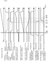
- the operation of the DCT 1 will be described with reference to Fig. 2 .
- the ECU 20 synchronously engages the start gear DG2 and the support gear SG1 to the second input shaft 12 and the first input shaft 11, respectively.
- the ECU 20 simultaneously brings the first clutch C1 and the second clutch C2 into a half clutch state with respect to the first input shaft 11 and the second input shaft 12, respectively. In this way, both clutches C1 and C2 transmit the torque at the moment of the start.
- the first clutch C1 on the support gear SG1 side takes part of the torque transmission.
- the input rotational speed Nin and the output rotational speed Nout detected by the first-clutch input-rotational-speed sensor 23 and the first-clutch output-rotational-speed sensor 24 are sent to the ECU 20, and the ECU 20 calculates a rotational speed difference ⁇ N therebetween (Nin - Nout).
- this rotational speed difference ⁇ N falls below a set value Nlim which is a predetermined value
- the ECU 20 fully disconnects the first clutch C1 on the support gear SG1 side in the half clutch state from the first input shaft 11 as shown in Part (c) of Fig. 2 .
- the ECU 20 releases the synchronous engagement of the support gear SG1 and brings the acceleration gear AG3 into a synchronously engaged state. Note that while this operation is performed, the torque transmission is still being performed on the start gear DG2 side and therefore the acceleration of the vehicle is still continuing.
- the ECU 20 fully connects the second clutch C2 on the start gear DG2 side to the second input shaft 12. If the speed is to be accelerated, the ECU 20 fully disconnects the second clutch C2 on the start gear DG2 side from the second input shaft 12 and fully connects the first clutch C1 on the acceleration gear AG3 side to the first input shaft 11.
- both clutches C1 and C2 linked to these gears may result in double engagement and stop the operation.
- the clutches C1 and C2 linked to the gears are in a half clutch state, hence absorbing the rotational speed difference.
- both clutches C1 and C2 can be used simultaneously.
- the first clutch C1 is fully disconnected when that rotational speed difference ⁇ N falls below the set value Nlim. In this way, it is possible to prevent the first clutch from slipping and being worn unnecessarily.
- the second clutch C2 is fully connected after synchronously engaging, to the first input shaft 11, the acceleration gear AG3 which has a gear ratio higher than the start gear DG2 by one speed. In this way, the acceleration can be done smoothly by simply switching the clutches C1 and C2.
- step S1 the ECU 20 performs step S1 of determining whether or not the vehicle is stopped. If determining that the vehicle is stopped, the ECU 20 then performs step S2 of fully disconnecting the first clutch C1 from the first input shaft 11 or the second clutch C2 from the second input shaft 12. Then, the ECU 20 performs step S3 of synchronously engaging the start gear DG2 and the support gear SG1 to the second input shaft 12 or the first input shaft 11. In step S3, the ECU 20 synchronously engages the start gear DG2 and the support gear SG1 by operating the shift operation mechanism 22 to swing the coupling sleeve S2 and the coupling sleeve S1.
- step S4 the ECU 20 performs step S4 of determining whether or not an operation to start the vehicle is performed. If determining that an operation to start the vehicle is performed, the ECU 20 then performs step S5 of connecting the first clutch C1 and the second clutch C2 to the first input shaft 11 and the second input shaft 12 in a half clutch state, respectively. By step S5, the power from the crankshaft 2 can be transmitted to both clutches C1 and C2 and to the output shaft 3 at the moment of the start of the vehicle.
- step S6 the ECU 20 performs step S6 of determining whether or not the second clutch C2 is fully connected to the second input shaft 12. Since the second clutch C2 has been set to a half clutch state in step S5, the ECU 20 performs next step S7 of determining whether or not the first clutch C1 is fully disconnected from the first input shaft 11. Since the first clutch C1 has likewise been set to a half clutch state in step S5, the ECU 20 proceeds to the next step.
- step S8 of calculating the rotational speed difference ⁇ N between the input rotational speed Nin and the output rotational speed Nout of the first clutch C1.
- step S9 of determining whether or not the rotational speed difference ⁇ N is smaller than the set value Nlim which is a predetermined threshold. Since the gear ratio of the support gear SG1 is smaller than that of the start gear DG2, the rotational speed difference ⁇ N reaches the coinciding point earlier than the other. If the value of the rotational speed difference ⁇ N reaches 0, i.e. the coinciding point, the first clutch C1 starts to slip and gets worn unnecessarily.
- the ECU 20 returns to step S6 and performs steps S6 to S9 again.
- step S10 of fully disconnecting the first clutch C1 from the first input shaft 11.
- step S10 the ECU 20 then returns to step S6.
- the first clutch C1 is fully disconnected
- the second clutch C2 is in a half clutch state
- the start gear DG2 is synchronously engaged
- the support gear SG1 is synchronously engaged.
- step S6 it is "N" in step S6, and the ECU 20 proceeds to step S7. If determining in step S7 that the first clutch C1 is fully disconnected, the ECU 20 then performs step S11 of determining whether or not the synchronous engagement of the support gear SG1 is released. Since the synchronous engagement of the support gear SG1 is not released, the ECU 20 performs next step S12 of releasing the synchronous engagement of the support gear SG1. Once completing step S12, the ECU 20 returns to step S6. At this point, the first clutch C1 is fully disconnected, the second clutch C2 is in a half clutch state, the start gear DG2 is synchronously engaged, and the support gear SG1 is released from its synchronous engagement.
- step S13 of bringing the acceleration gear AG3 into a synchronously engaged state.
- step S14 of fully connecting the second clutch C2 to the second input shaft 12.
- step S14 the ECU 20 returns to step S6.
- the first clutch C1 is fully disconnected
- the second clutch C2 is fully connected
- the start gear DG2 is synchronously engaged
- the support gear SG1 is released from its synchronous engagement
- the acceleration gear AG3 is synchronously engaged.
- This control method ends when the second clutch C2 is determined as being fully connected in step S6.
- the load on the second clutch C2 on the start gear DG2 side is reduced since both clutches C1 and C2 are used for start.
- the wear of the second clutch C2 can be reduced.
- the replacement interval for both clutches C1 and C2 can be made longer.
- the above-described operation and effect can be achieved as long as both clutches C1 and C2 can be operated independently and simultaneously.
- no additional component is needed for a conventional DCT. Accordingly, the cost can be reduced.
- the start gear DG2 is always the same gear each time start is performed, the wear of both clutches C1 and C2 can be reduced without changing the feel during start.
- a start operation is performed.
- the first clutch C1 and the second clutch C2 are brought into a half clutch state.
- the torque can be transmitted through both clutches C1 and C2.
- the input rotational speed Nin of the support gear SG1 becomes constant after a short period of time, while the output rotational speed Nout keeps increasing gradually, thereby decreasing the rotational speed difference ⁇ N gradually.
- the rotational speed difference ⁇ N falls below the set value Nlim, and the first clutch C1 on the support gear SG1 side starts to be fully disconnected.
- a vehicle equipped with the above-described DCT 1 can make the wear of both clutches C1 and C2 even and therefore make the replacement interval for both clutches C1 and C2 longer than conventional cases. Moreover, the above-described operation and effect can be achieved without changing the feel during start, and therefore a vehicle with good driving comfort can be provided.
- the method of controlling a dual clutch transmission of the present invention can reduce the load on the clutch on the start gear side and thus reduce the wear thereof and therefore make the clutch replacement interval longer, without requiring any additional component and also without changing the feel during start. Accordingly, the method of controlling a dual clutch transmission of the present invention can be utilized in large-sized vehicles such as trucks equipped with a dual clutch transmission to achieve low fuel consumption via smooth gear shift operations.
Landscapes
- Engineering & Computer Science (AREA)
- General Engineering & Computer Science (AREA)
- Mechanical Engineering (AREA)
- Control Of Transmission Device (AREA)
- Structure Of Transmissions (AREA)
- Hydraulic Clutches, Magnetic Clutches, Fluid Clutches, And Fluid Joints (AREA)
Claims (3)
- Un procédé de commande d'une transmission à double embrayage (1) qui inclut au moins un premier arbre d'entrée (11) configuré pour être connecté à un premier embrayage (C1) et un deuxième arbre d'entrée (12) configuré pour être connecté à un deuxième embrayage (C2), et dans laquelle un jeu d'engrenages impairs et un jeu d'engrenages pairs sont agencés à chaque étape pour alterner respectivement entre les premier et deuxième arbres d'entrée (11, 12) et un arbre de sortie (3), et dans un cas de démarrage de transmission de puissance d'une source de puissance à l'arbre de sortie (3), la transmission de la puissance est démarrée par le fait d'engager de manière synchrone un engrenage de démarrage (DG2) lequel est l'un des engrenages destinés au démarrage sur le deuxième arbre d'entrée (12) et de connecter le deuxième embrayage (C2) au deuxième arbre d'entrée (12), où
le procédé comprend, au moment du démarrage de la transmission de la puissance de la source de puissance à l'arbre de sortie (3), le fait d'engager de manière synchrone l'engrenage de démarrage (DG2) sur le deuxième arbre d'entrée (12) et d'engager de manière synchrone un engrenage de support (SG1) sur le premier arbre d'entrée (11), respectivement, et de connecter simultanément le premier embrayage (C1) partiellement au premier arbre d'entrée (11) et de connecter le deuxième embrayage (C2) partiellement au deuxième arbre d'entrée (12), respectivement, l'engrenage de support (SG1) ayant un rapport d'engrenage inférieur à celui de l'engrenage de démarrage (DG2) d'une vitesse ou plus ;
le fait de déconnecter le premier embrayage (C1) du premier arbre d'entrée (11) lorsqu'une différence entre une vitesse de rotation communiquée au premier embrayage (C1) et une vitesse de rotation fournie par le premier embrayage (C1) tombe au-dessous d'un seuil prédéterminé et que le démarrage à l'aide des deux embrayages (C1, C2) se termine ;
le fait de libérer l'engagement synchrone entre l'engrenage de support (SG1) et le premier arbre d'entrée (11) ;
le fait d'engager de manière synchrone un engrenage d'accélération (AG3) sur le premier arbre d'entrée (11), l'engrenage d'accélération (AG3) ayant un rapport d'engrenage supérieur à celui de l'engrenage de démarrage (DG2) d'une vitesse ;
et puis, le procédé étant caractérisé par
le fait de connecter complètement le deuxième embrayage (C2) au deuxième arbre d'entrée (12),
où le premier embrayage (C1) demeure complètement déconnecté. - Une transmission à double embrayage (1) qui inclut au moins un premier arbre d'entrée (11) configuré pour être connecté à un premier embrayage (C1) et un deuxième arbre d'entrée (12) configuré pour être connecté à un deuxième embrayage (C2), et dans laquelle un jeu d'engrenages impairs et un jeu d'engrenages pairs sont agencés à chaque étape pour alterner respectivement entre les premier et deuxième arbres d'entrée (11, 12) et un arbre de sortie (3), et dans un cas de démarrage de transmission de puissance d'une source de puissance à l'arbre de sortie (3), la transmission de la puissance est démarrée par le fait d'engager de manière synchrone un engrenage de démarrage (DG2) lequel est l'un des engrenages destinés au démarrage sur le deuxième arbre d'entrée (12) et de connecter le deuxième embrayage (C2) au deuxième arbre d'entrée (12), où
la transmission à double embrayage (1) comprend un engrenage de support (SG1) et un dispositif de commande (20), l'engrenage de support (SG1) ayant un rapport d'engrenage inférieur à celui de l'engrenage de démarrage (DG2) d'une vitesse ou plus, et
le dispositif de commande (20) inclut une commande pour, au moment du démarrage de la transmission de la puissance de la source de puissance à l'arbre de sortie (3), engager de manière synchrone l'engrenage de démarrage (DG2) sur le deuxième arbre d'entrée (12) et engager de manière synchrone l'engrenage de support (SG1) sur le premier arbre d'entrée (11), respectivement, et une commande pour connecter simultanément le premier embrayage (C1) partiellement au premier arbre d'entrée (11) et le deuxième embrayage (C2) partiellement au deuxième arbre d'entrée (12), respectivement, où
la transmission à double embrayage (1) comprend en sus
un engrenage d'accélération (AG3) ayant un rapport d'engrenage supérieur à celui de l'engrenage de démarrage (DG2) d'une vitesse,
un capteur de vitesse de rotation d'entrée (23) configuré pour détecter une vitesse de rotation communiquée au premier embrayage (C1), et
un capteur de vitesse de rotation de sortie (24) configuré pour détecter une vitesse de rotation fournie par le premier embrayage (C1), et
le dispositif de commande (20) inclut en sus
une commande pour déterminer si la valeur d'une différence entre la vitesse de rotation communiquée au premier embrayage (C1) et la vitesse de rotation fournie par le premier embrayage (C1) tombe au-dessous d'un seuil prédéterminé ou non,
une commande pour déconnecter complètement le premier embrayage (C1) du premier arbre d'entrée (11) lorsque la valeur de la différence entre la vitesse de rotation communiquée au premier embrayage (C1) et la vitesse de rotation fournie par le premier embrayage (C1) tombe au-dessous du seuil prédéterminé et que le démarrage à l'aide des deux embrayages (C1, C2) se termine,
une commande pour libérer l'engagement synchrone entre l'engrenage de support (SG1) et le premier arbre d'entrée (11) et engager de manière synchrone l'engrenage d'accélération (AG3) sur l'arbre d'entrée (11), où la transmission à double embrayage (1) est caractérisée en ce que le dispositif de commande (20) inclut en sus
une commande pour connecter complètement le deuxième embrayage (C2) au deuxième arbre d'entrée (12), où le premier embrayage (C1) demeure complètement déconnecté. - Un véhicule équipé de la transmission à double embrayage (1) selon la revendication 2.
Applications Claiming Priority (2)
| Application Number | Priority Date | Filing Date | Title |
|---|---|---|---|
| JP2011148151A JP5899682B2 (ja) | 2011-07-04 | 2011-07-04 | デュアルクラッチ式変速機の制御方法とデュアルクラッチ式変速機とそれを搭載した車両 |
| PCT/JP2012/066703 WO2013005673A1 (fr) | 2011-07-04 | 2012-06-29 | Procédé de commande de transmission à double embrayage, transmission à double embrayage et véhicule équipé de cette transmission |
Publications (3)
| Publication Number | Publication Date |
|---|---|
| EP2730816A1 EP2730816A1 (fr) | 2014-05-14 |
| EP2730816A4 EP2730816A4 (fr) | 2016-08-17 |
| EP2730816B1 true EP2730816B1 (fr) | 2021-03-24 |
Family
ID=47437025
Family Applications (1)
| Application Number | Title | Priority Date | Filing Date |
|---|---|---|---|
| EP12808085.0A Active EP2730816B1 (fr) | 2011-07-04 | 2012-06-29 | Procédé de commande de transmission à double embrayage, transmission à double embrayage et véhicule équipé de cette transmission |
Country Status (5)
| Country | Link |
|---|---|
| US (1) | US9556934B2 (fr) |
| EP (1) | EP2730816B1 (fr) |
| JP (1) | JP5899682B2 (fr) |
| CN (1) | CN103620270B (fr) |
| WO (1) | WO2013005673A1 (fr) |
Families Citing this family (9)
| Publication number | Priority date | Publication date | Assignee | Title |
|---|---|---|---|---|
| BR112015030831B1 (pt) * | 2013-06-12 | 2022-03-29 | Volvo Truck Corporation | Método para balanceamento de desgaste de embreagem |
| WO2015048963A1 (fr) * | 2013-10-04 | 2015-04-09 | Schaeffler Technologies AG & Co. KG | Procédé de commande d'une chaîne cinématique comprenant une boîte de vitesses à double embrayage |
| KR20160062292A (ko) * | 2014-11-24 | 2016-06-02 | 현대오트론 주식회사 | 듀얼 클러치 변속기의 제어 방법 및 제어 장치 |
| KR101865999B1 (ko) | 2015-11-04 | 2018-06-11 | 현대자동차주식회사 | 차량용 클러치의 스턱 방지방법 |
| US20180128351A1 (en) * | 2016-11-04 | 2018-05-10 | Gregory Mordukhovich | Split torque dual clutch transmission for concentric input shafts |
| US10525817B2 (en) * | 2018-05-21 | 2020-01-07 | Earl E. Irwin | Supplemental transmission assembly |
| JP6843095B2 (ja) * | 2018-07-04 | 2021-03-17 | 本田技研工業株式会社 | 車両用制御装置 |
| CN111379832A (zh) * | 2018-12-27 | 2020-07-07 | 长城汽车股份有限公司 | 一种单输出轴变速器 |
| DE102020110610B4 (de) * | 2020-04-20 | 2022-08-11 | Audi Aktiengesellschaft | Verfahren zum Betreiben eines Doppelkupplungsgetriebes eines Kraftfahrzeugs sowie Kraftfahrzeug |
Citations (1)
| Publication number | Priority date | Publication date | Assignee | Title |
|---|---|---|---|---|
| DE10232832A1 (de) * | 2002-07-19 | 2004-02-05 | Zf Friedrichshafen Ag | Verfahren zum Anfahren bei einem Mehrfachkupplungsgetriebe, insbesondere bei einem Doppelkupplungsgetriebe |
Family Cites Families (14)
| Publication number | Priority date | Publication date | Assignee | Title |
|---|---|---|---|---|
| DE19950696A1 (de) * | 1999-10-21 | 2001-04-26 | Volkswagen Ag | Doppelkupplungsgetriebe und Verfahren zur Steuerung eines automatisierten Doppelkupplungsgetriebes |
| DE10015296A1 (de) * | 2000-02-12 | 2001-08-16 | Bosch Gmbh Robert | Verfahren zum Anfahren eines Kraffahrzeuges mit Doppelkupplungsgetriebe |
| US6463821B1 (en) * | 2001-06-29 | 2002-10-15 | Daimlerchrysler Corporation | Method of controlling a transmission having a dual clutch system |
| WO2004036079A2 (fr) * | 2002-10-11 | 2004-04-29 | Luk Lamellen Und Kupplungsbau Beteiligungs Kg | Procede et systeme de commande d'au moins un actionneur dans la chaine cinematique d'un vehicule |
| WO2004096597A1 (fr) * | 2003-05-02 | 2004-11-11 | Luk Lamellen Und Kupplungsbau Beteiligungs Kg | Transmission comprenant une boite de vitesses a double embrayage et procede pour commander une telle transmission |
| JP3963868B2 (ja) * | 2003-06-23 | 2007-08-22 | トヨタ自動車株式会社 | ハイブリッド駆動装置の制御装置 |
| DE102005006556A1 (de) * | 2004-02-17 | 2005-09-08 | Volkswagen Ag | Verfahren zur Betätigung mindestens zweier parallel im Antriebsstrang eines Kraftfahrzeugs drehmomentübertragenden Kupplungen und Getriebesteuerung |
| JP2006132562A (ja) | 2004-11-02 | 2006-05-25 | Nissan Motor Co Ltd | ツインクラッチ式マニュアルトランスミッションのクラッチ偏摩耗時変速制御装置 |
| JP4235203B2 (ja) * | 2005-12-26 | 2009-03-11 | ジヤトコ株式会社 | ツインクラッチ式変速機の発進制御装置及び発進制御方法 |
| JP4650263B2 (ja) * | 2005-12-28 | 2011-03-16 | トヨタ自動車株式会社 | 動力伝達装置の制御装置 |
| JP5211373B2 (ja) | 2007-05-15 | 2013-06-12 | 株式会社 神崎高級工機製作所 | 作業運搬車のデュアルクラッチ式変速装置 |
| JP5136129B2 (ja) * | 2008-03-12 | 2013-02-06 | いすゞ自動車株式会社 | 車両用デュアルクラッチ式変速機 |
| JP2011112174A (ja) * | 2009-11-27 | 2011-06-09 | Mitsubishi Fuso Truck & Bus Corp | 車両用変速機制御装置 |
| JP6088726B2 (ja) | 2011-07-04 | 2017-03-01 | いすゞ自動車株式会社 | デュアルクラッチ式変速機の制御方法とデュアルクラッチ式変速機とそれを搭載した車両 |
-
2011
- 2011-07-04 JP JP2011148151A patent/JP5899682B2/ja not_active Expired - Fee Related
-
2012
- 2012-06-29 CN CN201280031712.9A patent/CN103620270B/zh active Active
- 2012-06-29 US US14/130,480 patent/US9556934B2/en active Active
- 2012-06-29 EP EP12808085.0A patent/EP2730816B1/fr active Active
- 2012-06-29 WO PCT/JP2012/066703 patent/WO2013005673A1/fr active Application Filing
Patent Citations (1)
| Publication number | Priority date | Publication date | Assignee | Title |
|---|---|---|---|---|
| DE10232832A1 (de) * | 2002-07-19 | 2004-02-05 | Zf Friedrichshafen Ag | Verfahren zum Anfahren bei einem Mehrfachkupplungsgetriebe, insbesondere bei einem Doppelkupplungsgetriebe |
Also Published As
| Publication number | Publication date |
|---|---|
| US9556934B2 (en) | 2017-01-31 |
| EP2730816A4 (fr) | 2016-08-17 |
| CN103620270B (zh) | 2016-07-06 |
| WO2013005673A1 (fr) | 2013-01-10 |
| JP2013015183A (ja) | 2013-01-24 |
| EP2730816A1 (fr) | 2014-05-14 |
| CN103620270A (zh) | 2014-03-05 |
| US20140150583A1 (en) | 2014-06-05 |
| JP5899682B2 (ja) | 2016-04-06 |
Similar Documents
| Publication | Publication Date | Title |
|---|---|---|
| EP2730816B1 (fr) | Procédé de commande de transmission à double embrayage, transmission à double embrayage et véhicule équipé de cette transmission | |
| EP2730814B1 (fr) | Procédé de commande de transmission à double embrayage, transmission à double embrayage et véhicule équipé de cette transmission | |
| EP2733393B1 (fr) | Procédé de commande pour transmission à double embrayage, transmission à double embrayage et véhicule chargé de cette transmission | |
| RU2376175C1 (ru) | Устройство управления транспортным средством | |
| EP2653754B1 (fr) | Dispositif de commande pour transmission à double embrayage et procédé de commande pour transmission à double embrayage | |
| EP2730815A1 (fr) | Procédé de commande d'une transmission à double embrayage, transmission à double embrayage et véhicule équipé de cette transmission | |
| CN102278461A (zh) | 动力换挡变速器中扭矩方向转换的控制 | |
| US20180266519A1 (en) | Automatic manual transmission and method for the same | |
| JP4502103B2 (ja) | 自動変速機 | |
| JP2013047532A (ja) | デュアルクラッチ式自動変速機 | |
| JP5552136B2 (ja) | 自動変速機の制御装置 | |
| JP5685160B2 (ja) | 機械式自動変速装置の制御システム | |
| CN108291630B (zh) | 双离合器式变速器的控制装置 | |
| JP2003130151A (ja) | 自動変速機 | |
| JP2004278767A (ja) | 車両用自動変速機の制御装置 | |
| JP2019074103A (ja) | デュアルクラッチ式変速機 |
Legal Events
| Date | Code | Title | Description |
|---|---|---|---|
| PUAI | Public reference made under article 153(3) epc to a published international application that has entered the european phase |
Free format text: ORIGINAL CODE: 0009012 |
|
| 17P | Request for examination filed |
Effective date: 20140113 |
|
| AK | Designated contracting states |
Kind code of ref document: A1 Designated state(s): AL AT BE BG CH CY CZ DE DK EE ES FI FR GB GR HR HU IE IS IT LI LT LU LV MC MK MT NL NO PL PT RO RS SE SI SK SM TR |
|
| DAX | Request for extension of the european patent (deleted) | ||
| RA4 | Supplementary search report drawn up and despatched (corrected) |
Effective date: 20160714 |
|
| RIC1 | Information provided on ipc code assigned before grant |
Ipc: F16H 61/688 20060101ALI20160708BHEP Ipc: F16H 61/02 20060101AFI20160708BHEP |
|
| STAA | Information on the status of an ep patent application or granted ep patent |
Free format text: STATUS: EXAMINATION IS IN PROGRESS |
|
| 17Q | First examination report despatched |
Effective date: 20190409 |
|
| GRAP | Despatch of communication of intention to grant a patent |
Free format text: ORIGINAL CODE: EPIDOSNIGR1 |
|
| STAA | Information on the status of an ep patent application or granted ep patent |
Free format text: STATUS: GRANT OF PATENT IS INTENDED |
|
| INTG | Intention to grant announced |
Effective date: 20201118 |
|
| GRAS | Grant fee paid |
Free format text: ORIGINAL CODE: EPIDOSNIGR3 |
|
| GRAA | (expected) grant |
Free format text: ORIGINAL CODE: 0009210 |
|
| STAA | Information on the status of an ep patent application or granted ep patent |
Free format text: STATUS: THE PATENT HAS BEEN GRANTED |
|
| AK | Designated contracting states |
Kind code of ref document: B1 Designated state(s): AL AT BE BG CH CY CZ DE DK EE ES FI FR GB GR HR HU IE IS IT LI LT LU LV MC MK MT NL NO PL PT RO RS SE SI SK SM TR |
|
| REG | Reference to a national code |
Ref country code: GB Ref legal event code: FG4D |
|
| REG | Reference to a national code |
Ref country code: CH Ref legal event code: EP |
|
| REG | Reference to a national code |
Ref country code: DE Ref legal event code: R096 Ref document number: 602012074919 Country of ref document: DE |
|
| REG | Reference to a national code |
Ref country code: IE Ref legal event code: FG4D |
|
| REG | Reference to a national code |
Ref country code: AT Ref legal event code: REF Ref document number: 1374803 Country of ref document: AT Kind code of ref document: T Effective date: 20210415 |
|
| REG | Reference to a national code |
Ref country code: LT Ref legal event code: MG9D |
|
| PG25 | Lapsed in a contracting state [announced via postgrant information from national office to epo] |
Ref country code: FI Free format text: LAPSE BECAUSE OF FAILURE TO SUBMIT A TRANSLATION OF THE DESCRIPTION OR TO PAY THE FEE WITHIN THE PRESCRIBED TIME-LIMIT Effective date: 20210324 Ref country code: HR Free format text: LAPSE BECAUSE OF FAILURE TO SUBMIT A TRANSLATION OF THE DESCRIPTION OR TO PAY THE FEE WITHIN THE PRESCRIBED TIME-LIMIT Effective date: 20210324 Ref country code: GR Free format text: LAPSE BECAUSE OF FAILURE TO SUBMIT A TRANSLATION OF THE DESCRIPTION OR TO PAY THE FEE WITHIN THE PRESCRIBED TIME-LIMIT Effective date: 20210625 Ref country code: BG Free format text: LAPSE BECAUSE OF FAILURE TO SUBMIT A TRANSLATION OF THE DESCRIPTION OR TO PAY THE FEE WITHIN THE PRESCRIBED TIME-LIMIT Effective date: 20210624 Ref country code: NO Free format text: LAPSE BECAUSE OF FAILURE TO SUBMIT A TRANSLATION OF THE DESCRIPTION OR TO PAY THE FEE WITHIN THE PRESCRIBED TIME-LIMIT Effective date: 20210624 |
|
| PG25 | Lapsed in a contracting state [announced via postgrant information from national office to epo] |
Ref country code: SE Free format text: LAPSE BECAUSE OF FAILURE TO SUBMIT A TRANSLATION OF THE DESCRIPTION OR TO PAY THE FEE WITHIN THE PRESCRIBED TIME-LIMIT Effective date: 20210324 Ref country code: RS Free format text: LAPSE BECAUSE OF FAILURE TO SUBMIT A TRANSLATION OF THE DESCRIPTION OR TO PAY THE FEE WITHIN THE PRESCRIBED TIME-LIMIT Effective date: 20210324 Ref country code: LV Free format text: LAPSE BECAUSE OF FAILURE TO SUBMIT A TRANSLATION OF THE DESCRIPTION OR TO PAY THE FEE WITHIN THE PRESCRIBED TIME-LIMIT Effective date: 20210324 |
|
| REG | Reference to a national code |
Ref country code: NL Ref legal event code: MP Effective date: 20210324 |
|
| REG | Reference to a national code |
Ref country code: AT Ref legal event code: MK05 Ref document number: 1374803 Country of ref document: AT Kind code of ref document: T Effective date: 20210324 |
|
| PG25 | Lapsed in a contracting state [announced via postgrant information from national office to epo] |
Ref country code: NL Free format text: LAPSE BECAUSE OF FAILURE TO SUBMIT A TRANSLATION OF THE DESCRIPTION OR TO PAY THE FEE WITHIN THE PRESCRIBED TIME-LIMIT Effective date: 20210324 |
|
| PG25 | Lapsed in a contracting state [announced via postgrant information from national office to epo] |
Ref country code: SM Free format text: LAPSE BECAUSE OF FAILURE TO SUBMIT A TRANSLATION OF THE DESCRIPTION OR TO PAY THE FEE WITHIN THE PRESCRIBED TIME-LIMIT Effective date: 20210324 Ref country code: AT Free format text: LAPSE BECAUSE OF FAILURE TO SUBMIT A TRANSLATION OF THE DESCRIPTION OR TO PAY THE FEE WITHIN THE PRESCRIBED TIME-LIMIT Effective date: 20210324 Ref country code: CZ Free format text: LAPSE BECAUSE OF FAILURE TO SUBMIT A TRANSLATION OF THE DESCRIPTION OR TO PAY THE FEE WITHIN THE PRESCRIBED TIME-LIMIT Effective date: 20210324 Ref country code: EE Free format text: LAPSE BECAUSE OF FAILURE TO SUBMIT A TRANSLATION OF THE DESCRIPTION OR TO PAY THE FEE WITHIN THE PRESCRIBED TIME-LIMIT Effective date: 20210324 Ref country code: LT Free format text: LAPSE BECAUSE OF FAILURE TO SUBMIT A TRANSLATION OF THE DESCRIPTION OR TO PAY THE FEE WITHIN THE PRESCRIBED TIME-LIMIT Effective date: 20210324 |
|
| PG25 | Lapsed in a contracting state [announced via postgrant information from national office to epo] |
Ref country code: ES Free format text: LAPSE BECAUSE OF FAILURE TO SUBMIT A TRANSLATION OF THE DESCRIPTION OR TO PAY THE FEE WITHIN THE PRESCRIBED TIME-LIMIT Effective date: 20210324 Ref country code: PT Free format text: LAPSE BECAUSE OF FAILURE TO SUBMIT A TRANSLATION OF THE DESCRIPTION OR TO PAY THE FEE WITHIN THE PRESCRIBED TIME-LIMIT Effective date: 20210726 Ref country code: PL Free format text: LAPSE BECAUSE OF FAILURE TO SUBMIT A TRANSLATION OF THE DESCRIPTION OR TO PAY THE FEE WITHIN THE PRESCRIBED TIME-LIMIT Effective date: 20210324 Ref country code: SK Free format text: LAPSE BECAUSE OF FAILURE TO SUBMIT A TRANSLATION OF THE DESCRIPTION OR TO PAY THE FEE WITHIN THE PRESCRIBED TIME-LIMIT Effective date: 20210324 Ref country code: IS Free format text: LAPSE BECAUSE OF FAILURE TO SUBMIT A TRANSLATION OF THE DESCRIPTION OR TO PAY THE FEE WITHIN THE PRESCRIBED TIME-LIMIT Effective date: 20210724 Ref country code: RO Free format text: LAPSE BECAUSE OF FAILURE TO SUBMIT A TRANSLATION OF THE DESCRIPTION OR TO PAY THE FEE WITHIN THE PRESCRIBED TIME-LIMIT Effective date: 20210324 |
|
| REG | Reference to a national code |
Ref country code: DE Ref legal event code: R097 Ref document number: 602012074919 Country of ref document: DE |
|
| PG25 | Lapsed in a contracting state [announced via postgrant information from national office to epo] |
Ref country code: MC Free format text: LAPSE BECAUSE OF FAILURE TO SUBMIT A TRANSLATION OF THE DESCRIPTION OR TO PAY THE FEE WITHIN THE PRESCRIBED TIME-LIMIT Effective date: 20210324 Ref country code: AL Free format text: LAPSE BECAUSE OF FAILURE TO SUBMIT A TRANSLATION OF THE DESCRIPTION OR TO PAY THE FEE WITHIN THE PRESCRIBED TIME-LIMIT Effective date: 20210324 Ref country code: DK Free format text: LAPSE BECAUSE OF FAILURE TO SUBMIT A TRANSLATION OF THE DESCRIPTION OR TO PAY THE FEE WITHIN THE PRESCRIBED TIME-LIMIT Effective date: 20210324 |
|
| REG | Reference to a national code |
Ref country code: CH Ref legal event code: PL |
|
| PLBE | No opposition filed within time limit |
Free format text: ORIGINAL CODE: 0009261 |
|
| STAA | Information on the status of an ep patent application or granted ep patent |
Free format text: STATUS: NO OPPOSITION FILED WITHIN TIME LIMIT |
|
| PG25 | Lapsed in a contracting state [announced via postgrant information from national office to epo] |
Ref country code: SI Free format text: LAPSE BECAUSE OF FAILURE TO SUBMIT A TRANSLATION OF THE DESCRIPTION OR TO PAY THE FEE WITHIN THE PRESCRIBED TIME-LIMIT Effective date: 20210324 |
|
| 26N | No opposition filed |
Effective date: 20220104 |
|
| REG | Reference to a national code |
Ref country code: BE Ref legal event code: MM Effective date: 20210630 |
|
| PG25 | Lapsed in a contracting state [announced via postgrant information from national office to epo] |
Ref country code: LU Free format text: LAPSE BECAUSE OF NON-PAYMENT OF DUE FEES Effective date: 20210629 |
|
| PG25 | Lapsed in a contracting state [announced via postgrant information from national office to epo] |
Ref country code: LI Free format text: LAPSE BECAUSE OF NON-PAYMENT OF DUE FEES Effective date: 20210630 Ref country code: IE Free format text: LAPSE BECAUSE OF NON-PAYMENT OF DUE FEES Effective date: 20210629 Ref country code: CH Free format text: LAPSE BECAUSE OF NON-PAYMENT OF DUE FEES Effective date: 20210630 |
|
| PG25 | Lapsed in a contracting state [announced via postgrant information from national office to epo] |
Ref country code: IS Free format text: LAPSE BECAUSE OF FAILURE TO SUBMIT A TRANSLATION OF THE DESCRIPTION OR TO PAY THE FEE WITHIN THE PRESCRIBED TIME-LIMIT Effective date: 20210724 |
|
| PG25 | Lapsed in a contracting state [announced via postgrant information from national office to epo] |
Ref country code: BE Free format text: LAPSE BECAUSE OF NON-PAYMENT OF DUE FEES Effective date: 20210630 |
|
| PGFP | Annual fee paid to national office [announced via postgrant information from national office to epo] |
Ref country code: GB Payment date: 20220427 Year of fee payment: 11 |
|
| PGFP | Annual fee paid to national office [announced via postgrant information from national office to epo] |
Ref country code: FR Payment date: 20220624 Year of fee payment: 11 |
|
| PG25 | Lapsed in a contracting state [announced via postgrant information from national office to epo] |
Ref country code: IT Free format text: LAPSE BECAUSE OF FAILURE TO SUBMIT A TRANSLATION OF THE DESCRIPTION OR TO PAY THE FEE WITHIN THE PRESCRIBED TIME-LIMIT Effective date: 20210324 |
|
| PG25 | Lapsed in a contracting state [announced via postgrant information from national office to epo] |
Ref country code: HU Free format text: LAPSE BECAUSE OF FAILURE TO SUBMIT A TRANSLATION OF THE DESCRIPTION OR TO PAY THE FEE WITHIN THE PRESCRIBED TIME-LIMIT; INVALID AB INITIO Effective date: 20120629 Ref country code: CY Free format text: LAPSE BECAUSE OF FAILURE TO SUBMIT A TRANSLATION OF THE DESCRIPTION OR TO PAY THE FEE WITHIN THE PRESCRIBED TIME-LIMIT Effective date: 20210324 |
|
| PGFP | Annual fee paid to national office [announced via postgrant information from national office to epo] |
Ref country code: DE Payment date: 20220630 Year of fee payment: 12 |
|
| GBPC | Gb: european patent ceased through non-payment of renewal fee |
Effective date: 20230629 |
|
| PG25 | Lapsed in a contracting state [announced via postgrant information from national office to epo] |
Ref country code: MK Free format text: LAPSE BECAUSE OF FAILURE TO SUBMIT A TRANSLATION OF THE DESCRIPTION OR TO PAY THE FEE WITHIN THE PRESCRIBED TIME-LIMIT Effective date: 20210324 Ref country code: GB Free format text: LAPSE BECAUSE OF NON-PAYMENT OF DUE FEES Effective date: 20230629 |