EP2730734A2 - Dispositif d'insertion bidirectionnel pour une porte coulissante moyenne - Google Patents
Dispositif d'insertion bidirectionnel pour une porte coulissante moyenne Download PDFInfo
- Publication number
- EP2730734A2 EP2730734A2 EP13187575.9A EP13187575A EP2730734A2 EP 2730734 A2 EP2730734 A2 EP 2730734A2 EP 13187575 A EP13187575 A EP 13187575A EP 2730734 A2 EP2730734 A2 EP 2730734A2
- Authority
- EP
- European Patent Office
- Prior art keywords
- driver
- sliding door
- housing
- coupling
- bidirectional
- Prior art date
- Legal status (The legal status is an assumption and is not a legal conclusion. Google has not performed a legal analysis and makes no representation as to the accuracy of the status listed.)
- Granted
Links
- 230000002457 bidirectional effect Effects 0.000 title claims description 24
- 230000008878 coupling Effects 0.000 claims abstract description 40
- 238000010168 coupling process Methods 0.000 claims abstract description 40
- 238000005859 coupling reaction Methods 0.000 claims abstract description 40
- 238000013016 damping Methods 0.000 claims description 5
- 230000000694 effects Effects 0.000 abstract description 2
- 101100390736 Danio rerio fign gene Proteins 0.000 description 2
- 101100390738 Mus musculus Fign gene Proteins 0.000 description 2
- CNQCVBJFEGMYDW-UHFFFAOYSA-N lawrencium atom Chemical compound [Lr] CNQCVBJFEGMYDW-UHFFFAOYSA-N 0.000 description 2
- 239000012530 fluid Substances 0.000 description 1
- 239000002184 metal Substances 0.000 description 1
Images


Classifications
-
- E—FIXED CONSTRUCTIONS
- E05—LOCKS; KEYS; WINDOW OR DOOR FITTINGS; SAFES
- E05F—DEVICES FOR MOVING WINGS INTO OPEN OR CLOSED POSITION; CHECKS FOR WINGS; WING FITTINGS NOT OTHERWISE PROVIDED FOR, CONCERNED WITH THE FUNCTIONING OF THE WING
- E05F5/00—Braking devices, e.g. checks; Stops; Buffers
- E05F5/003—Braking devices, e.g. checks; Stops; Buffers for sliding wings
-
- E—FIXED CONSTRUCTIONS
- E05—LOCKS; KEYS; WINDOW OR DOOR FITTINGS; SAFES
- E05F—DEVICES FOR MOVING WINGS INTO OPEN OR CLOSED POSITION; CHECKS FOR WINGS; WING FITTINGS NOT OTHERWISE PROVIDED FOR, CONCERNED WITH THE FUNCTIONING OF THE WING
- E05F1/00—Closers or openers for wings, not otherwise provided for in this subclass
- E05F1/08—Closers or openers for wings, not otherwise provided for in this subclass spring-actuated, e.g. for horizontally sliding wings
- E05F1/16—Closers or openers for wings, not otherwise provided for in this subclass spring-actuated, e.g. for horizontally sliding wings for sliding wings
-
- E—FIXED CONSTRUCTIONS
- E05—LOCKS; KEYS; WINDOW OR DOOR FITTINGS; SAFES
- E05Y—INDEXING SCHEME RELATING TO HINGES OR OTHER SUSPENSION DEVICES FOR DOORS, WINDOWS OR WINGS AND DEVICES FOR MOVING WINGS INTO OPEN OR CLOSED POSITION, CHECKS FOR WINGS AND WING FITTINGS NOT OTHERWISE PROVIDED FOR, CONCERNED WITH THE FUNCTIONING OF THE WING
- E05Y2201/00—Constructional elements; Accessories therefore
- E05Y2201/10—Covers; Housings
-
- E—FIXED CONSTRUCTIONS
- E05—LOCKS; KEYS; WINDOW OR DOOR FITTINGS; SAFES
- E05Y—INDEXING SCHEME RELATING TO HINGES OR OTHER SUSPENSION DEVICES FOR DOORS, WINDOWS OR WINGS AND DEVICES FOR MOVING WINGS INTO OPEN OR CLOSED POSITION, CHECKS FOR WINGS AND WING FITTINGS NOT OTHERWISE PROVIDED FOR, CONCERNED WITH THE FUNCTIONING OF THE WING
- E05Y2201/00—Constructional elements; Accessories therefore
- E05Y2201/20—Brakes; Disengaging means, e.g. clutches; Holders, e.g. locks; Stops; Accessories therefore
- E05Y2201/262—Brakes; Disengaging means, e.g. clutches; Holders, e.g. locks; Stops; Accessories therefore characterised by type of motion
- E05Y2201/264—Brakes; Disengaging means, e.g. clutches; Holders, e.g. locks; Stops; Accessories therefore characterised by type of motion linear
-
- E—FIXED CONSTRUCTIONS
- E05—LOCKS; KEYS; WINDOW OR DOOR FITTINGS; SAFES
- E05Y—INDEXING SCHEME RELATING TO HINGES OR OTHER SUSPENSION DEVICES FOR DOORS, WINDOWS OR WINGS AND DEVICES FOR MOVING WINGS INTO OPEN OR CLOSED POSITION, CHECKS FOR WINGS AND WING FITTINGS NOT OTHERWISE PROVIDED FOR, CONCERNED WITH THE FUNCTIONING OF THE WING
- E05Y2201/00—Constructional elements; Accessories therefore
- E05Y2201/40—Motors; Magnets; Springs; Weights; Accessories therefore
- E05Y2201/404—Motors; Magnets; Springs; Weights; Accessories therefore characterised by the function
- E05Y2201/41—Motors; Magnets; Springs; Weights; Accessories therefore characterised by the function for closing
- E05Y2201/412—Motors; Magnets; Springs; Weights; Accessories therefore characterised by the function for closing for the final closing movement
-
- E—FIXED CONSTRUCTIONS
- E05—LOCKS; KEYS; WINDOW OR DOOR FITTINGS; SAFES
- E05Y—INDEXING SCHEME RELATING TO HINGES OR OTHER SUSPENSION DEVICES FOR DOORS, WINDOWS OR WINGS AND DEVICES FOR MOVING WINGS INTO OPEN OR CLOSED POSITION, CHECKS FOR WINGS AND WING FITTINGS NOT OTHERWISE PROVIDED FOR, CONCERNED WITH THE FUNCTIONING OF THE WING
- E05Y2201/00—Constructional elements; Accessories therefore
- E05Y2201/40—Motors; Magnets; Springs; Weights; Accessories therefore
- E05Y2201/404—Motors; Magnets; Springs; Weights; Accessories therefore characterised by the function
- E05Y2201/422—Motors; Magnets; Springs; Weights; Accessories therefore characterised by the function for opening
- E05Y2201/424—Motors; Magnets; Springs; Weights; Accessories therefore characterised by the function for opening for the final opening movement
-
- E—FIXED CONSTRUCTIONS
- E05—LOCKS; KEYS; WINDOW OR DOOR FITTINGS; SAFES
- E05Y—INDEXING SCHEME RELATING TO HINGES OR OTHER SUSPENSION DEVICES FOR DOORS, WINDOWS OR WINGS AND DEVICES FOR MOVING WINGS INTO OPEN OR CLOSED POSITION, CHECKS FOR WINGS AND WING FITTINGS NOT OTHERWISE PROVIDED FOR, CONCERNED WITH THE FUNCTIONING OF THE WING
- E05Y2800/00—Details, accessories and auxiliary operations not otherwise provided for
- E05Y2800/20—Combinations of elements
- E05Y2800/21—Combinations of elements of identical elements, e.g. of identical compression springs
-
- E—FIXED CONSTRUCTIONS
- E05—LOCKS; KEYS; WINDOW OR DOOR FITTINGS; SAFES
- E05Y—INDEXING SCHEME RELATING TO HINGES OR OTHER SUSPENSION DEVICES FOR DOORS, WINDOWS OR WINGS AND DEVICES FOR MOVING WINGS INTO OPEN OR CLOSED POSITION, CHECKS FOR WINGS AND WING FITTINGS NOT OTHERWISE PROVIDED FOR, CONCERNED WITH THE FUNCTIONING OF THE WING
- E05Y2800/00—Details, accessories and auxiliary operations not otherwise provided for
- E05Y2800/20—Combinations of elements
- E05Y2800/23—Combinations of elements of elements of different categories
- E05Y2800/24—Combinations of elements of elements of different categories of springs and brakes
-
- E—FIXED CONSTRUCTIONS
- E05—LOCKS; KEYS; WINDOW OR DOOR FITTINGS; SAFES
- E05Y—INDEXING SCHEME RELATING TO HINGES OR OTHER SUSPENSION DEVICES FOR DOORS, WINDOWS OR WINGS AND DEVICES FOR MOVING WINGS INTO OPEN OR CLOSED POSITION, CHECKS FOR WINGS AND WING FITTINGS NOT OTHERWISE PROVIDED FOR, CONCERNED WITH THE FUNCTIONING OF THE WING
- E05Y2800/00—Details, accessories and auxiliary operations not otherwise provided for
- E05Y2800/73—Single use of elements
-
- E—FIXED CONSTRUCTIONS
- E05—LOCKS; KEYS; WINDOW OR DOOR FITTINGS; SAFES
- E05Y—INDEXING SCHEME RELATING TO HINGES OR OTHER SUSPENSION DEVICES FOR DOORS, WINDOWS OR WINGS AND DEVICES FOR MOVING WINGS INTO OPEN OR CLOSED POSITION, CHECKS FOR WINGS AND WING FITTINGS NOT OTHERWISE PROVIDED FOR, CONCERNED WITH THE FUNCTIONING OF THE WING
- E05Y2800/00—Details, accessories and auxiliary operations not otherwise provided for
- E05Y2800/74—Specific positions
- E05Y2800/75—Specific positions intermediate
-
- E—FIXED CONSTRUCTIONS
- E05—LOCKS; KEYS; WINDOW OR DOOR FITTINGS; SAFES
- E05Y—INDEXING SCHEME RELATING TO HINGES OR OTHER SUSPENSION DEVICES FOR DOORS, WINDOWS OR WINGS AND DEVICES FOR MOVING WINGS INTO OPEN OR CLOSED POSITION, CHECKS FOR WINGS AND WING FITTINGS NOT OTHERWISE PROVIDED FOR, CONCERNED WITH THE FUNCTIONING OF THE WING
- E05Y2900/00—Application of doors, windows, wings or fittings thereof
- E05Y2900/20—Application of doors, windows, wings or fittings thereof for furnitures, e.g. cabinets
Definitions
- the invention relates to a bidirectional intake device for pulling a sliding door on both sides into a middle door position according to the preamble of claim 1, as well as a sliding door arrangement with such a bidirectional intake device.
- Such a bidirectional collection device is, for example, by DE 20 2010 007 230 U1 known.
- Unidirectional collection devices for drawing in a movable furniture part, such as e.g. a drawer or a sliding door, in its closed end position are well known.
- Such known unidirectional intake devices have a slidably guided driver for releasable coupling with the furniture part.
- the furniture part is in its closed end position in engagement with the retracted driver and takes in its opening movement the driver from a retracted end position against the action of a catch spring in a tilted locking end position, in which the furniture part is decoupled in the opening direction of the driver.
- the furniture part releases the driver from the locking end position and is retracted therefrom, driven by the pull-in spring, into the closed end position.
- Each of the two unidirectional collection devices has a separate guide housing, in which a driver and a linear damper are arranged.
- the housing also has the guides for the driver and that the linear damper independently of the drivers on the housing can be fastened.
- the attachable linear damper offers the possibility of selecting and installing the optimum linear damper from several linear dampers, each with different damping characteristics.
- each of the two unidirectional collection devices optionally a single linear damper or more parallel linear damper fastened so as to produce the corresponding damping characteristic depending on the weight class of the sliding door.
- the driver is formed in two parts, namely from a linearly guided in the leadership of the housing guide member and a guided in the leadership of the housing linear and tiltable tilting element which is pivotally mounted on the guide element.
- This two-part design of the driver has the advantage that the damping forces of the linear damper or have no effect on the tilting movement of the driver.
- the guide element has a bearing journal and the tilting element has a bearing receptacle rotatably mounted on the bearing journal, or vice versa.
- the scope of the invention also includes a sliding door arrangement with a sliding door and with a bidirectional draw-in device as described above, the sliding door being motion-coupled with the slide in its middle door position in both directions.
- bidirectional feeder 1 is used for both sides retracting a displaceable in the direction of the double arrow 2 mounted central sliding door (center door) 3 in a closed center door position.
- the feeder device 1 is for example attached to an upper or lower guide rail (not shown) of the sliding door 3 or on the top floor or in the cabinet base of a sliding door cabinet.
- the collection device 1 comprises two unidirectional collection devices 4 which are effective in opposite directions and , in the exemplary embodiment shown, are identically constructed and mirror images of one another in a housing 5 , as well as a coupling carriage 6 in lateral guides (eg guide grooves) 7 of the housing 5 in the direction of the double arrow 2 is guided displaceably.
- the coupling carriage 6 is arranged between the sliding door 3 and the drawing-in devices 4 and serves, as described in detail below, for coupling the sliding door 3 with the drawing-in devices 4.
- Each retraction device 4 has a guide housing 8 with a guide track 9 , in which a carriage-shaped carrier 10 is displaceably guided between a retracted and an extended end position.
- Fig. 1 c is the driver 10 of the right feed device 4 in its retracted end position and the driver 10 of the left feed device 4 in its extended end position shown.
- the driver 10 has on its the coupling carriage 6 side facing a recess 11 ( Fig. 1c ) and is by a pull-in spring 12 applied to its retracted position.
- the retraction movement of the driver 10 is damped by a designed as a linear damper 13 fluid damper, the linearly displaceable piston is entrained by the driver 10 in the extension direction.
- a piston rod of the piston 10 may be attached to the driver.
- the guide track 9 initially has a straight guide section 9a , which then merges at the end of the guide track 9 into a transverse guide section 9b , which defines the extended end position of the driver 10.
- the coupling carriage 6 has a middle slide arm 14 and two outer slide arms 15 , which are articulated on the middle slide arm 14 in each case via axes 16 , that is connected in a tiltable manner.
- the middle slide arm 14 is guided in the lateral guides 7 of the housing 5.
- the free ends of the outer slide arms 15 are also guided in the lateral guides 7 via guide pins 17 .
- the outer slide arms 15 each have a projection 18 on their side facing the driver 10, and a protruding coupling element 19 on their side facing the sliding door 3, which can be formed, for example, by an obliquely projecting arm.
- a straight central guide portion 20 of the guide 7 close each have an inclined guide portion 21 (FIG. Fig. 1 c) two straight outer guide portions 22 , which are due to the oblique guide portions 21 relative to the central guide portion 20 in the direction away from the slide door 3 set back by a dimension A and as shown, for example, can be parallel to the middle guide portion 20.
- the middle guide portion 20 is more than twice as long as the distance of the two axes 16, and the outer guide portions 22 are at least as long as the distance between the axis 16 and the guide pin 17th
- the sliding door 3 has on its side facing the coupling slide 6 two driver projections 23 whose outer distance from the distance between the two Coupling elements 19 corresponds.
- the driver projections 23 may be formed for example by a bolt or an angled sheet metal.
- Fig. 1a the collection device 1 is shown in its normal position, in which the sliding door 3 is retracted in its closed center door position.
- the two drivers 10 of the intake devices 4 are in their retracted end positions, and the coupling carriage 6 engages with its two projections 18 in the recesses 11 of the two drivers 10 a.
- the driver projections 23 of the sliding door 3 are fixed between the two coupling elements 19, whereby the coupling slide 6 is coupled in motion with the sliding door 3 in both directions.
- the two axes 16 are located in the middle guide portion 20 and the guide pin 17 respectively in the outer guide portions 22, wherein the outer slide arms 15 engage with their projections 18 in the recesses 11 of the driver 10.
- the guide pin 17 of the right slide arm 15 is transferred via the inclined guide portion 21 in the middle guide portion 20, whereby the right slide arm 15 tilted counterclockwise about the axis 16 and its projection 18 no longer engages in the recess 11 of the right-hand carrier 10 ,
- the driver 10 of the left feed device 4 is taken over the engaging in its recess 11 projection 18 of the left slide arm 15 from the coupling carriage 6 to the left against the action of the pull-in spring 12, which is thereby tensioned.
- the driver 10 of the left feed device 4 is pushed against the action of the catch spring 12 further to the left until it finally 9a at the end of the straight guide portion 9a over the transverse guide portion tilted in a locking end position.
- the recess 11 of the driver 10 to the opening direction 24 open, so that the left slide arm 15 is decoupled in the opening direction 24 of the driver 10.
- the sliding door 3 If the sliding door 3 starting from Fig. 1 c pushed back in the middle door position in the closing direction 25 , the sliding door 3 first meets with its right Mit supportivevorsprung 23 on the right coupling element 19 of the coupling carriage 6, which is thereby taken in the closing direction 25.
- the left axis 16 is transferred via the inclined guide portion 21 back into the middle guide portion 20, whereby the left coupling element 19 is transversely displaced by the dimension A in the direction of the sliding door 3 and engages behind the left Mit supportivevorsprung 23 in the closing direction 25.
- the coupling carriage 6 runs with its left projection 18 in the laterally open recess 11 of the locked left-hand carrier 10 and starts the driver 10 to rotate out of its locking end position, whereby the projection 18 is set in the recess 11 at the same time.
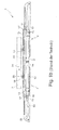
- Fig. 2 shows the bidirectional collection device 101 according to the invention , which is identical in function to the bidirectional collection device 1 of Fig. 1 is. Therefore, in Fig. 2 for functionally identical parts the same reference numbers as in Fig. 1 used.
- the bidirectional collection device 101 has no separate guide housing, but the driver 10 and the linear damper 13 of each unidirectional collection device 4 are independent of each other attached to the housing 5.
- the housing 5 has two housing halves, of which in Fig. 2 the upper one is removed and therefore only the lower one is visible.
- the two housing halves have, in addition to the guides 7 for the coupling slide 6 and the guides 9 for the driver 10 and also trough-shaped receptacles (not shown), in which the linear damper 13 is inserted and thereby secured in the housing 5.
- the coupling carriages 6 are each slidably and tiltably guided by means of their two projecting two guide pins 16, 17 and the drivers 10 by means of their two projecting two guide pins 101, 102 on both sides.
- the two drivers 10 are connected by the pull-in spring 12 with each other and thereby acted upon in their retracted end position.
- each of the two unidirectional collection devices 4 can be on the same housing 5 for each of the two unidirectional collection devices 4 either one or more, z. B. as present two parallel linear damper 13 are attached.
- the driver 10 is in two parts of a guide member 103 and a pivotally mounted thereon tilting 104 formed.
- the guide element 103 has the elongated guide pin 101 protruding on both sides, with which it is guided linearly displaceably in the straight guide section 9a of the guide track 9.
- the tilting element 104 has the circular guide pin 102 protruding on both sides, with which it can be tilted linearly in the straight guide section 9a of the guide track 9 and then tilted into the locking end position in the transverse guide section 9b is guided.
- the guide element 103 has a bearing journal 105 and the tilting element 104 has a bearing receptacle 106 rotatably mounted on the bearing journal 105.
- the linear damper 13 are formed as a piston damper with piston rod 107 , which are respectively inserted into a blind bore 108 of the guide member 103 and thus both act on the guide member 103.
- the two-part design of the driver 10 has the advantage that the forces acting on the guide member 103 damping forces of the linear damper or 13 have no influence on the tilting movement of the tilting element 104.
Priority Applications (2)
| Application Number | Priority Date | Filing Date | Title |
|---|---|---|---|
| SI201330779T SI2730734T1 (sl) | 2012-11-13 | 2013-10-07 | Dvosmerna uvlečna naprava za sprednja drsna vrata |
| PL13187575T PL2730734T3 (pl) | 2012-11-13 | 2013-10-07 | Dwukierunkowe urządzenie wciągające dla środkowych drzwi przesuwnych |
Applications Claiming Priority (1)
| Application Number | Priority Date | Filing Date | Title |
|---|---|---|---|
| DE202012104360U DE202012104360U1 (de) | 2012-11-13 | 2012-11-13 | Bidirektionale Einzugsvorrichtung für eine mittlere Schiebetür |
Publications (3)
| Publication Number | Publication Date |
|---|---|
| EP2730734A2 true EP2730734A2 (fr) | 2014-05-14 |
| EP2730734A3 EP2730734A3 (fr) | 2016-07-13 |
| EP2730734B1 EP2730734B1 (fr) | 2017-09-13 |
Family
ID=47427054
Family Applications (1)
| Application Number | Title | Priority Date | Filing Date |
|---|---|---|---|
| EP13187575.9A Active EP2730734B1 (fr) | 2012-11-13 | 2013-10-07 | Dispositif d'entraînement bidirectionnel pour une porte coulissante médiane |
Country Status (6)
| Country | Link |
|---|---|
| EP (1) | EP2730734B1 (fr) |
| DE (1) | DE202012104360U1 (fr) |
| DK (1) | DK2730734T3 (fr) |
| ES (1) | ES2651680T3 (fr) |
| PL (1) | PL2730734T3 (fr) |
| SI (1) | SI2730734T1 (fr) |
Cited By (2)
| Publication number | Priority date | Publication date | Assignee | Title |
|---|---|---|---|---|
| CN105507721A (zh) * | 2016-01-19 | 2016-04-20 | 许姜德 | 一种双向阻尼器装置 |
| EP3581746A1 (fr) * | 2018-06-12 | 2019-12-18 | Günther Zimmer | Dispositif combiné d'amortissement et de fermeture pour une porte centrale |
Families Citing this family (3)
| Publication number | Priority date | Publication date | Assignee | Title |
|---|---|---|---|---|
| DE102014103074B4 (de) * | 2014-03-07 | 2016-06-30 | Carl Stahl Kromer Gmbh | Schiebeteil mit Federzug |
| DE102016007885A1 (de) * | 2016-06-29 | 2018-01-04 | Günther Zimmer | Mitteltür-Zuziehvorrichtung mit Übertragungsschlitten |
| DE102018122289A1 (de) * | 2018-09-12 | 2020-03-12 | Hettich-Oni Gmbh & Co. Kg | Vorrichtung zum mechanischen Schließen eines bewegbaren Möbelteils und Verfahren zum Öffnen und Schließen eines bewegbaren Möbelteils |
Citations (1)
| Publication number | Priority date | Publication date | Assignee | Title |
|---|---|---|---|---|
| DE202010007230U1 (de) | 2010-05-27 | 2010-08-26 | Häfele GmbH & Co. KG | Bidirektionale Einzugsvorrichtung für eine mittlere Schiebetür |
Family Cites Families (3)
| Publication number | Priority date | Publication date | Assignee | Title |
|---|---|---|---|---|
| WO2007111424A1 (fr) * | 2006-03-27 | 2007-10-04 | Yoon Sik Park | Moyen de fermeture automatique |
| DE102008009046B4 (de) * | 2008-02-13 | 2014-10-02 | Günther Zimmer | Beschleunigungs- und Verzögerungsvorrichtung mit zwei Mitnahmeelementen |
| DE202011110715U1 (de) * | 2011-04-01 | 2015-11-04 | Karl Simon Gmbh & Co. Kg | Einzugvorrichtung |
-
2012
- 2012-11-13 DE DE202012104360U patent/DE202012104360U1/de not_active Expired - Lifetime
-
2013
- 2013-10-07 DK DK13187575.9T patent/DK2730734T3/en active
- 2013-10-07 ES ES13187575.9T patent/ES2651680T3/es active Active
- 2013-10-07 PL PL13187575T patent/PL2730734T3/pl unknown
- 2013-10-07 EP EP13187575.9A patent/EP2730734B1/fr active Active
- 2013-10-07 SI SI201330779T patent/SI2730734T1/sl unknown
Patent Citations (1)
| Publication number | Priority date | Publication date | Assignee | Title |
|---|---|---|---|---|
| DE202010007230U1 (de) | 2010-05-27 | 2010-08-26 | Häfele GmbH & Co. KG | Bidirektionale Einzugsvorrichtung für eine mittlere Schiebetür |
Cited By (3)
| Publication number | Priority date | Publication date | Assignee | Title |
|---|---|---|---|---|
| CN105507721A (zh) * | 2016-01-19 | 2016-04-20 | 许姜德 | 一种双向阻尼器装置 |
| CN105507721B (zh) * | 2016-01-19 | 2017-06-27 | 许姜德 | 一种双向阻尼器装置 |
| EP3581746A1 (fr) * | 2018-06-12 | 2019-12-18 | Günther Zimmer | Dispositif combiné d'amortissement et de fermeture pour une porte centrale |
Also Published As
| Publication number | Publication date |
|---|---|
| SI2730734T1 (sl) | 2017-12-29 |
| PL2730734T3 (pl) | 2018-02-28 |
| DE202012104360U1 (de) | 2012-11-21 |
| EP2730734A3 (fr) | 2016-07-13 |
| EP2730734B1 (fr) | 2017-09-13 |
| DK2730734T3 (en) | 2017-12-18 |
| ES2651680T3 (es) | 2018-01-29 |
Similar Documents
| Publication | Publication Date | Title |
|---|---|---|
| EP2001327B1 (fr) | Mecanisme d'entrainement pour piece de meuble montee a deplacement dans ou sur un meuble | |
| EP2661195B1 (fr) | Dispositif d'éjection verrouillable à mécanisme de surcharge | |
| EP2390448B1 (fr) | Dispositif de rétraction bidirectionnel pour porte coulissante médiane | |
| EP3087866B1 (fr) | Armature pour une armoire angulaire et armoire angulaire dotée d'une armature | |
| EP3088646B1 (fr) | Dispositif de guidage pour une porte coulissante | |
| EP3084107B1 (fr) | Unité de rentrée et d'amortissement pour un élément coulissant | |
| EP1120066A2 (fr) | Dispositif de fermeture et/ou de retrait pour des éléments de meuble mobiles | |
| EP2488718B1 (fr) | Dispositif de rentrée automatique et d'amortissement | |
| EP2353445B2 (fr) | Glissière pour retracter des parties de meubles | |
| EP2956032B1 (fr) | Dispositif de guidage télescopique pour un élément de meuble mobile | |
| DE202008016409U1 (de) | Selbsteinzugsvorrichtung und Auszugsführung | |
| EP2730734B1 (fr) | Dispositif d'entraînement bidirectionnel pour une porte coulissante médiane | |
| EP1743550A1 (fr) | Dispositif de déplacement pour extensions de meuble, en particulier tiroirs | |
| EP2758618B1 (fr) | Plaque de montage mobile pour charnière de meuble | |
| DE202017100244U1 (de) | Duschabtrennung mit einer durch eine Feder-Dämpfer-Einheit aktiv in die Endstellungen bewegbaren Schiebetür | |
| DE102007059575A1 (de) | Dämpfungs- und Einzugseinrichtung für mindestens ein Schiebeelement, z.B. eine Schiebetür | |
| WO2012038339A1 (fr) | Dispositif de rentrée automatique pour un élément de meuble mobile | |
| EP3142516B1 (fr) | Dispositif de rétraction destiné à un meuble | |
| EP2992156B1 (fr) | Système de guidage d'une porte coulissante, porte coulissante et meuble | |
| EP2721236A1 (fr) | Charnière intérieure de 180 degrés pour un ensemble d'armoires en série | |
| DE102018100674A1 (de) | Möbelplatte mit einem Scharnier und Möbel mit einer derartigen Möbelplatte | |
| EP1384420B1 (fr) | Mécanisme de fermeture automatique amorti | |
| EP3296492A1 (fr) | Systeme de guidage de porte coulissante et porte coulissante comprenant un systeme de guidage et vehicule en etant equipe | |
| DE202012002884U1 (de) | Dämpfersystem | |
| EP3088647A1 (fr) | Système à rails pour un dispositif de guidage |
Legal Events
| Date | Code | Title | Description |
|---|---|---|---|
| PUAI | Public reference made under article 153(3) epc to a published international application that has entered the european phase |
Free format text: ORIGINAL CODE: 0009012 |
|
| 17P | Request for examination filed |
Effective date: 20131007 |
|
| AK | Designated contracting states |
Kind code of ref document: A2 Designated state(s): AL AT BE BG CH CY CZ DE DK EE ES FI FR GB GR HR HU IE IS IT LI LT LU LV MC MK MT NL NO PL PT RO RS SE SI SK SM TR |
|
| AX | Request for extension of the european patent |
Extension state: BA ME |
|
| PUAL | Search report despatched |
Free format text: ORIGINAL CODE: 0009013 |
|
| AK | Designated contracting states |
Kind code of ref document: A3 Designated state(s): AL AT BE BG CH CY CZ DE DK EE ES FI FR GB GR HR HU IE IS IT LI LT LU LV MC MK MT NL NO PL PT RO RS SE SI SK SM TR |
|
| AX | Request for extension of the european patent |
Extension state: BA ME |
|
| RIC1 | Information provided on ipc code assigned before grant |
Ipc: E05F 1/16 20060101ALI20160608BHEP Ipc: E05F 5/00 20060101AFI20160608BHEP |
|
| R17P | Request for examination filed (corrected) |
Effective date: 20160714 |
|
| RBV | Designated contracting states (corrected) |
Designated state(s): AL AT BE BG CH CY CZ DE DK EE ES FI FR GB GR HR HU IE IS IT LI LT LU LV MC MK MT NL NO PL PT RO RS SE SI SK SM TR |
|
| GRAP | Despatch of communication of intention to grant a patent |
Free format text: ORIGINAL CODE: EPIDOSNIGR1 |
|
| INTG | Intention to grant announced |
Effective date: 20170425 |
|
| GRAS | Grant fee paid |
Free format text: ORIGINAL CODE: EPIDOSNIGR3 |
|
| GRAA | (expected) grant |
Free format text: ORIGINAL CODE: 0009210 |
|
| AK | Designated contracting states |
Kind code of ref document: B1 Designated state(s): AL AT BE BG CH CY CZ DE DK EE ES FI FR GB GR HR HU IE IS IT LI LT LU LV MC MK MT NL NO PL PT RO RS SE SI SK SM TR |
|
| REG | Reference to a national code |
Ref country code: GB Ref legal event code: FG4D Free format text: NOT ENGLISH |
|
| REG | Reference to a national code |
Ref country code: CH Ref legal event code: EP |
|
| REG | Reference to a national code |
Ref country code: IE Ref legal event code: FG4D Free format text: LANGUAGE OF EP DOCUMENT: GERMAN |
|
| REG | Reference to a national code |
Ref country code: AT Ref legal event code: REF Ref document number: 928329 Country of ref document: AT Kind code of ref document: T Effective date: 20171015 |
|
| REG | Reference to a national code |
Ref country code: DE Ref legal event code: R096 Ref document number: 502013008329 Country of ref document: DE Ref country code: FR Ref legal event code: PLFP Year of fee payment: 5 |
|
| REG | Reference to a national code |
Ref country code: SE Ref legal event code: TRGR |
|
| REG | Reference to a national code |
Ref country code: DK Ref legal event code: T3 Effective date: 20171213 |
|
| REG | Reference to a national code |
Ref country code: NL Ref legal event code: FP |
|
| REG | Reference to a national code |
Ref country code: LT Ref legal event code: MG4D |
|
| REG | Reference to a national code |
Ref country code: ES Ref legal event code: FG2A Ref document number: 2651680 Country of ref document: ES Kind code of ref document: T3 Effective date: 20180129 |
|
| PG25 | Lapsed in a contracting state [announced via postgrant information from national office to epo] |
Ref country code: HR Free format text: LAPSE BECAUSE OF FAILURE TO SUBMIT A TRANSLATION OF THE DESCRIPTION OR TO PAY THE FEE WITHIN THE PRESCRIBED TIME-LIMIT Effective date: 20170913 Ref country code: NO Free format text: LAPSE BECAUSE OF FAILURE TO SUBMIT A TRANSLATION OF THE DESCRIPTION OR TO PAY THE FEE WITHIN THE PRESCRIBED TIME-LIMIT Effective date: 20171213 Ref country code: FI Free format text: LAPSE BECAUSE OF FAILURE TO SUBMIT A TRANSLATION OF THE DESCRIPTION OR TO PAY THE FEE WITHIN THE PRESCRIBED TIME-LIMIT Effective date: 20170913 Ref country code: LT Free format text: LAPSE BECAUSE OF FAILURE TO SUBMIT A TRANSLATION OF THE DESCRIPTION OR TO PAY THE FEE WITHIN THE PRESCRIBED TIME-LIMIT Effective date: 20170913 |
|
| PG25 | Lapsed in a contracting state [announced via postgrant information from national office to epo] |
Ref country code: GR Free format text: LAPSE BECAUSE OF FAILURE TO SUBMIT A TRANSLATION OF THE DESCRIPTION OR TO PAY THE FEE WITHIN THE PRESCRIBED TIME-LIMIT Effective date: 20171214 Ref country code: RS Free format text: LAPSE BECAUSE OF FAILURE TO SUBMIT A TRANSLATION OF THE DESCRIPTION OR TO PAY THE FEE WITHIN THE PRESCRIBED TIME-LIMIT Effective date: 20170913 Ref country code: BG Free format text: LAPSE BECAUSE OF FAILURE TO SUBMIT A TRANSLATION OF THE DESCRIPTION OR TO PAY THE FEE WITHIN THE PRESCRIBED TIME-LIMIT Effective date: 20171213 Ref country code: LV Free format text: LAPSE BECAUSE OF FAILURE TO SUBMIT A TRANSLATION OF THE DESCRIPTION OR TO PAY THE FEE WITHIN THE PRESCRIBED TIME-LIMIT Effective date: 20170913 |
|
| PG25 | Lapsed in a contracting state [announced via postgrant information from national office to epo] |
Ref country code: CZ Free format text: LAPSE BECAUSE OF FAILURE TO SUBMIT A TRANSLATION OF THE DESCRIPTION OR TO PAY THE FEE WITHIN THE PRESCRIBED TIME-LIMIT Effective date: 20170913 Ref country code: RO Free format text: LAPSE BECAUSE OF FAILURE TO SUBMIT A TRANSLATION OF THE DESCRIPTION OR TO PAY THE FEE WITHIN THE PRESCRIBED TIME-LIMIT Effective date: 20170913 |
|
| PG25 | Lapsed in a contracting state [announced via postgrant information from national office to epo] |
Ref country code: SM Free format text: LAPSE BECAUSE OF FAILURE TO SUBMIT A TRANSLATION OF THE DESCRIPTION OR TO PAY THE FEE WITHIN THE PRESCRIBED TIME-LIMIT Effective date: 20170913 Ref country code: SK Free format text: LAPSE BECAUSE OF FAILURE TO SUBMIT A TRANSLATION OF THE DESCRIPTION OR TO PAY THE FEE WITHIN THE PRESCRIBED TIME-LIMIT Effective date: 20170913 Ref country code: EE Free format text: LAPSE BECAUSE OF FAILURE TO SUBMIT A TRANSLATION OF THE DESCRIPTION OR TO PAY THE FEE WITHIN THE PRESCRIBED TIME-LIMIT Effective date: 20170913 Ref country code: IS Free format text: LAPSE BECAUSE OF FAILURE TO SUBMIT A TRANSLATION OF THE DESCRIPTION OR TO PAY THE FEE WITHIN THE PRESCRIBED TIME-LIMIT Effective date: 20180113 |
|
| REG | Reference to a national code |
Ref country code: CH Ref legal event code: PL |
|
| REG | Reference to a national code |
Ref country code: DE Ref legal event code: R097 Ref document number: 502013008329 Country of ref document: DE |
|
| PG25 | Lapsed in a contracting state [announced via postgrant information from national office to epo] |
Ref country code: MC Free format text: LAPSE BECAUSE OF FAILURE TO SUBMIT A TRANSLATION OF THE DESCRIPTION OR TO PAY THE FEE WITHIN THE PRESCRIBED TIME-LIMIT Effective date: 20170913 |
|
| PLBE | No opposition filed within time limit |
Free format text: ORIGINAL CODE: 0009261 |
|
| STAA | Information on the status of an ep patent application or granted ep patent |
Free format text: STATUS: NO OPPOSITION FILED WITHIN TIME LIMIT |
|
| REG | Reference to a national code |
Ref country code: IE Ref legal event code: MM4A |
|
| PG25 | Lapsed in a contracting state [announced via postgrant information from national office to epo] |
Ref country code: LI Free format text: LAPSE BECAUSE OF NON-PAYMENT OF DUE FEES Effective date: 20171031 Ref country code: LU Free format text: LAPSE BECAUSE OF NON-PAYMENT OF DUE FEES Effective date: 20171007 Ref country code: CH Free format text: LAPSE BECAUSE OF NON-PAYMENT OF DUE FEES Effective date: 20171031 |
|
| 26N | No opposition filed |
Effective date: 20180614 |
|
| REG | Reference to a national code |
Ref country code: BE Ref legal event code: MM Effective date: 20171031 |
|
| PG25 | Lapsed in a contracting state [announced via postgrant information from national office to epo] |
Ref country code: BE Free format text: LAPSE BECAUSE OF NON-PAYMENT OF DUE FEES Effective date: 20171031 |
|
| PG25 | Lapsed in a contracting state [announced via postgrant information from national office to epo] |
Ref country code: MT Free format text: LAPSE BECAUSE OF FAILURE TO SUBMIT A TRANSLATION OF THE DESCRIPTION OR TO PAY THE FEE WITHIN THE PRESCRIBED TIME-LIMIT Effective date: 20170913 |
|
| REG | Reference to a national code |
Ref country code: FR Ref legal event code: PLFP Year of fee payment: 6 |
|
| PG25 | Lapsed in a contracting state [announced via postgrant information from national office to epo] |
Ref country code: IE Free format text: LAPSE BECAUSE OF NON-PAYMENT OF DUE FEES Effective date: 20171007 |
|
| PG25 | Lapsed in a contracting state [announced via postgrant information from national office to epo] |
Ref country code: HU Free format text: LAPSE BECAUSE OF FAILURE TO SUBMIT A TRANSLATION OF THE DESCRIPTION OR TO PAY THE FEE WITHIN THE PRESCRIBED TIME-LIMIT; INVALID AB INITIO Effective date: 20131007 |
|
| PG25 | Lapsed in a contracting state [announced via postgrant information from national office to epo] |
Ref country code: CY Free format text: LAPSE BECAUSE OF NON-PAYMENT OF DUE FEES Effective date: 20170913 |
|
| PG25 | Lapsed in a contracting state [announced via postgrant information from national office to epo] |
Ref country code: MK Free format text: LAPSE BECAUSE OF FAILURE TO SUBMIT A TRANSLATION OF THE DESCRIPTION OR TO PAY THE FEE WITHIN THE PRESCRIBED TIME-LIMIT Effective date: 20170913 |
|
| REG | Reference to a national code |
Ref country code: AT Ref legal event code: MM01 Ref document number: 928329 Country of ref document: AT Kind code of ref document: T Effective date: 20181007 |
|
| PG25 | Lapsed in a contracting state [announced via postgrant information from national office to epo] |
Ref country code: AT Free format text: LAPSE BECAUSE OF NON-PAYMENT OF DUE FEES Effective date: 20181007 |
|
| PG25 | Lapsed in a contracting state [announced via postgrant information from national office to epo] |
Ref country code: PT Free format text: LAPSE BECAUSE OF FAILURE TO SUBMIT A TRANSLATION OF THE DESCRIPTION OR TO PAY THE FEE WITHIN THE PRESCRIBED TIME-LIMIT Effective date: 20170913 |
|
| PG25 | Lapsed in a contracting state [announced via postgrant information from national office to epo] |
Ref country code: AL Free format text: LAPSE BECAUSE OF FAILURE TO SUBMIT A TRANSLATION OF THE DESCRIPTION OR TO PAY THE FEE WITHIN THE PRESCRIBED TIME-LIMIT Effective date: 20170913 |
|
| P01 | Opt-out of the competence of the unified patent court (upc) registered |
Effective date: 20230630 |
|
| PGFP | Annual fee paid to national office [announced via postgrant information from national office to epo] |
Ref country code: TR Payment date: 20230929 Year of fee payment: 11 |
|
| PGFP | Annual fee paid to national office [announced via postgrant information from national office to epo] |
Ref country code: PL Payment date: 20230818 Year of fee payment: 11 Ref country code: NL Payment date: 20231023 Year of fee payment: 11 |
|
| PGFP | Annual fee paid to national office [announced via postgrant information from national office to epo] |
Ref country code: GB Payment date: 20231025 Year of fee payment: 11 |
|
| PGFP | Annual fee paid to national office [announced via postgrant information from national office to epo] |
Ref country code: ES Payment date: 20231117 Year of fee payment: 11 |
|
| PGFP | Annual fee paid to national office [announced via postgrant information from national office to epo] |
Ref country code: SI Payment date: 20230926 Year of fee payment: 11 Ref country code: SE Payment date: 20231025 Year of fee payment: 11 Ref country code: IT Payment date: 20231031 Year of fee payment: 11 Ref country code: FR Payment date: 20231023 Year of fee payment: 11 Ref country code: DK Payment date: 20231025 Year of fee payment: 11 Ref country code: DE Payment date: 20231024 Year of fee payment: 11 |