EP2730734A2 - Bidirectional intake device for a medium-sized sliding door - Google Patents
Bidirectional intake device for a medium-sized sliding door Download PDFInfo
- Publication number
- EP2730734A2 EP2730734A2 EP13187575.9A EP13187575A EP2730734A2 EP 2730734 A2 EP2730734 A2 EP 2730734A2 EP 13187575 A EP13187575 A EP 13187575A EP 2730734 A2 EP2730734 A2 EP 2730734A2
- Authority
- EP
- European Patent Office
- Prior art keywords
- driver
- sliding door
- housing
- coupling
- bidirectional
- Prior art date
- Legal status (The legal status is an assumption and is not a legal conclusion. Google has not performed a legal analysis and makes no representation as to the accuracy of the status listed.)
- Granted
Links
- 230000002457 bidirectional effect Effects 0.000 title claims description 24
- 230000008878 coupling Effects 0.000 claims abstract description 40
- 238000010168 coupling process Methods 0.000 claims abstract description 40
- 238000005859 coupling reaction Methods 0.000 claims abstract description 40
- 238000013016 damping Methods 0.000 claims description 5
- 230000000694 effects Effects 0.000 abstract description 2
- 101100390736 Danio rerio fign gene Proteins 0.000 description 2
- 101100390738 Mus musculus Fign gene Proteins 0.000 description 2
- CNQCVBJFEGMYDW-UHFFFAOYSA-N lawrencium atom Chemical compound [Lr] CNQCVBJFEGMYDW-UHFFFAOYSA-N 0.000 description 2
- 239000012530 fluid Substances 0.000 description 1
- 239000002184 metal Substances 0.000 description 1
Images


Classifications
-
- E—FIXED CONSTRUCTIONS
- E05—LOCKS; KEYS; WINDOW OR DOOR FITTINGS; SAFES
- E05F—DEVICES FOR MOVING WINGS INTO OPEN OR CLOSED POSITION; CHECKS FOR WINGS; WING FITTINGS NOT OTHERWISE PROVIDED FOR, CONCERNED WITH THE FUNCTIONING OF THE WING
- E05F5/00—Braking devices, e.g. checks; Stops; Buffers
- E05F5/003—Braking devices, e.g. checks; Stops; Buffers for sliding wings
-
- E—FIXED CONSTRUCTIONS
- E05—LOCKS; KEYS; WINDOW OR DOOR FITTINGS; SAFES
- E05F—DEVICES FOR MOVING WINGS INTO OPEN OR CLOSED POSITION; CHECKS FOR WINGS; WING FITTINGS NOT OTHERWISE PROVIDED FOR, CONCERNED WITH THE FUNCTIONING OF THE WING
- E05F1/00—Closers or openers for wings, not otherwise provided for in this subclass
- E05F1/08—Closers or openers for wings, not otherwise provided for in this subclass spring-actuated, e.g. for horizontally sliding wings
- E05F1/16—Closers or openers for wings, not otherwise provided for in this subclass spring-actuated, e.g. for horizontally sliding wings for sliding wings
-
- E—FIXED CONSTRUCTIONS
- E05—LOCKS; KEYS; WINDOW OR DOOR FITTINGS; SAFES
- E05Y—INDEXING SCHEME RELATING TO HINGES OR OTHER SUSPENSION DEVICES FOR DOORS, WINDOWS OR WINGS AND DEVICES FOR MOVING WINGS INTO OPEN OR CLOSED POSITION, CHECKS FOR WINGS AND WING FITTINGS NOT OTHERWISE PROVIDED FOR, CONCERNED WITH THE FUNCTIONING OF THE WING
- E05Y2201/00—Constructional elements; Accessories therefore
- E05Y2201/10—Covers; Housings
-
- E—FIXED CONSTRUCTIONS
- E05—LOCKS; KEYS; WINDOW OR DOOR FITTINGS; SAFES
- E05Y—INDEXING SCHEME RELATING TO HINGES OR OTHER SUSPENSION DEVICES FOR DOORS, WINDOWS OR WINGS AND DEVICES FOR MOVING WINGS INTO OPEN OR CLOSED POSITION, CHECKS FOR WINGS AND WING FITTINGS NOT OTHERWISE PROVIDED FOR, CONCERNED WITH THE FUNCTIONING OF THE WING
- E05Y2201/00—Constructional elements; Accessories therefore
- E05Y2201/20—Brakes; Disengaging means, e.g. clutches; Holders, e.g. locks; Stops; Accessories therefore
- E05Y2201/262—Brakes; Disengaging means, e.g. clutches; Holders, e.g. locks; Stops; Accessories therefore characterised by type of motion
- E05Y2201/264—Brakes; Disengaging means, e.g. clutches; Holders, e.g. locks; Stops; Accessories therefore characterised by type of motion linear
-
- E—FIXED CONSTRUCTIONS
- E05—LOCKS; KEYS; WINDOW OR DOOR FITTINGS; SAFES
- E05Y—INDEXING SCHEME RELATING TO HINGES OR OTHER SUSPENSION DEVICES FOR DOORS, WINDOWS OR WINGS AND DEVICES FOR MOVING WINGS INTO OPEN OR CLOSED POSITION, CHECKS FOR WINGS AND WING FITTINGS NOT OTHERWISE PROVIDED FOR, CONCERNED WITH THE FUNCTIONING OF THE WING
- E05Y2201/00—Constructional elements; Accessories therefore
- E05Y2201/40—Motors; Magnets; Springs; Weights; Accessories therefore
- E05Y2201/404—Motors; Magnets; Springs; Weights; Accessories therefore characterised by the function
- E05Y2201/41—Motors; Magnets; Springs; Weights; Accessories therefore characterised by the function for closing
- E05Y2201/412—Motors; Magnets; Springs; Weights; Accessories therefore characterised by the function for closing for the final closing movement
-
- E—FIXED CONSTRUCTIONS
- E05—LOCKS; KEYS; WINDOW OR DOOR FITTINGS; SAFES
- E05Y—INDEXING SCHEME RELATING TO HINGES OR OTHER SUSPENSION DEVICES FOR DOORS, WINDOWS OR WINGS AND DEVICES FOR MOVING WINGS INTO OPEN OR CLOSED POSITION, CHECKS FOR WINGS AND WING FITTINGS NOT OTHERWISE PROVIDED FOR, CONCERNED WITH THE FUNCTIONING OF THE WING
- E05Y2201/00—Constructional elements; Accessories therefore
- E05Y2201/40—Motors; Magnets; Springs; Weights; Accessories therefore
- E05Y2201/404—Motors; Magnets; Springs; Weights; Accessories therefore characterised by the function
- E05Y2201/422—Motors; Magnets; Springs; Weights; Accessories therefore characterised by the function for opening
- E05Y2201/424—Motors; Magnets; Springs; Weights; Accessories therefore characterised by the function for opening for the final opening movement
-
- E—FIXED CONSTRUCTIONS
- E05—LOCKS; KEYS; WINDOW OR DOOR FITTINGS; SAFES
- E05Y—INDEXING SCHEME RELATING TO HINGES OR OTHER SUSPENSION DEVICES FOR DOORS, WINDOWS OR WINGS AND DEVICES FOR MOVING WINGS INTO OPEN OR CLOSED POSITION, CHECKS FOR WINGS AND WING FITTINGS NOT OTHERWISE PROVIDED FOR, CONCERNED WITH THE FUNCTIONING OF THE WING
- E05Y2800/00—Details, accessories and auxiliary operations not otherwise provided for
- E05Y2800/20—Combinations of elements
- E05Y2800/21—Combinations of elements of identical elements, e.g. of identical compression springs
-
- E—FIXED CONSTRUCTIONS
- E05—LOCKS; KEYS; WINDOW OR DOOR FITTINGS; SAFES
- E05Y—INDEXING SCHEME RELATING TO HINGES OR OTHER SUSPENSION DEVICES FOR DOORS, WINDOWS OR WINGS AND DEVICES FOR MOVING WINGS INTO OPEN OR CLOSED POSITION, CHECKS FOR WINGS AND WING FITTINGS NOT OTHERWISE PROVIDED FOR, CONCERNED WITH THE FUNCTIONING OF THE WING
- E05Y2800/00—Details, accessories and auxiliary operations not otherwise provided for
- E05Y2800/20—Combinations of elements
- E05Y2800/23—Combinations of elements of elements of different categories
- E05Y2800/24—Combinations of elements of elements of different categories of springs and brakes
-
- E—FIXED CONSTRUCTIONS
- E05—LOCKS; KEYS; WINDOW OR DOOR FITTINGS; SAFES
- E05Y—INDEXING SCHEME RELATING TO HINGES OR OTHER SUSPENSION DEVICES FOR DOORS, WINDOWS OR WINGS AND DEVICES FOR MOVING WINGS INTO OPEN OR CLOSED POSITION, CHECKS FOR WINGS AND WING FITTINGS NOT OTHERWISE PROVIDED FOR, CONCERNED WITH THE FUNCTIONING OF THE WING
- E05Y2800/00—Details, accessories and auxiliary operations not otherwise provided for
- E05Y2800/73—Single use of elements
-
- E—FIXED CONSTRUCTIONS
- E05—LOCKS; KEYS; WINDOW OR DOOR FITTINGS; SAFES
- E05Y—INDEXING SCHEME RELATING TO HINGES OR OTHER SUSPENSION DEVICES FOR DOORS, WINDOWS OR WINGS AND DEVICES FOR MOVING WINGS INTO OPEN OR CLOSED POSITION, CHECKS FOR WINGS AND WING FITTINGS NOT OTHERWISE PROVIDED FOR, CONCERNED WITH THE FUNCTIONING OF THE WING
- E05Y2800/00—Details, accessories and auxiliary operations not otherwise provided for
- E05Y2800/74—Specific positions
- E05Y2800/75—Specific positions intermediate
-
- E—FIXED CONSTRUCTIONS
- E05—LOCKS; KEYS; WINDOW OR DOOR FITTINGS; SAFES
- E05Y—INDEXING SCHEME RELATING TO HINGES OR OTHER SUSPENSION DEVICES FOR DOORS, WINDOWS OR WINGS AND DEVICES FOR MOVING WINGS INTO OPEN OR CLOSED POSITION, CHECKS FOR WINGS AND WING FITTINGS NOT OTHERWISE PROVIDED FOR, CONCERNED WITH THE FUNCTIONING OF THE WING
- E05Y2900/00—Application of doors, windows, wings or fittings thereof
- E05Y2900/20—Application of doors, windows, wings or fittings thereof for furnitures, e.g. cabinets
Definitions
- the invention relates to a bidirectional intake device for pulling a sliding door on both sides into a middle door position according to the preamble of claim 1, as well as a sliding door arrangement with such a bidirectional intake device.
- Such a bidirectional collection device is, for example, by DE 20 2010 007 230 U1 known.
- Unidirectional collection devices for drawing in a movable furniture part, such as e.g. a drawer or a sliding door, in its closed end position are well known.
- Such known unidirectional intake devices have a slidably guided driver for releasable coupling with the furniture part.
- the furniture part is in its closed end position in engagement with the retracted driver and takes in its opening movement the driver from a retracted end position against the action of a catch spring in a tilted locking end position, in which the furniture part is decoupled in the opening direction of the driver.
- the furniture part releases the driver from the locking end position and is retracted therefrom, driven by the pull-in spring, into the closed end position.
- Each of the two unidirectional collection devices has a separate guide housing, in which a driver and a linear damper are arranged.
- the housing also has the guides for the driver and that the linear damper independently of the drivers on the housing can be fastened.
- the attachable linear damper offers the possibility of selecting and installing the optimum linear damper from several linear dampers, each with different damping characteristics.
- each of the two unidirectional collection devices optionally a single linear damper or more parallel linear damper fastened so as to produce the corresponding damping characteristic depending on the weight class of the sliding door.
- the driver is formed in two parts, namely from a linearly guided in the leadership of the housing guide member and a guided in the leadership of the housing linear and tiltable tilting element which is pivotally mounted on the guide element.
- This two-part design of the driver has the advantage that the damping forces of the linear damper or have no effect on the tilting movement of the driver.
- the guide element has a bearing journal and the tilting element has a bearing receptacle rotatably mounted on the bearing journal, or vice versa.
- the scope of the invention also includes a sliding door arrangement with a sliding door and with a bidirectional draw-in device as described above, the sliding door being motion-coupled with the slide in its middle door position in both directions.
- bidirectional feeder 1 is used for both sides retracting a displaceable in the direction of the double arrow 2 mounted central sliding door (center door) 3 in a closed center door position.
- the feeder device 1 is for example attached to an upper or lower guide rail (not shown) of the sliding door 3 or on the top floor or in the cabinet base of a sliding door cabinet.
- the collection device 1 comprises two unidirectional collection devices 4 which are effective in opposite directions and , in the exemplary embodiment shown, are identically constructed and mirror images of one another in a housing 5 , as well as a coupling carriage 6 in lateral guides (eg guide grooves) 7 of the housing 5 in the direction of the double arrow 2 is guided displaceably.
- the coupling carriage 6 is arranged between the sliding door 3 and the drawing-in devices 4 and serves, as described in detail below, for coupling the sliding door 3 with the drawing-in devices 4.
- Each retraction device 4 has a guide housing 8 with a guide track 9 , in which a carriage-shaped carrier 10 is displaceably guided between a retracted and an extended end position.
- Fig. 1 c is the driver 10 of the right feed device 4 in its retracted end position and the driver 10 of the left feed device 4 in its extended end position shown.
- the driver 10 has on its the coupling carriage 6 side facing a recess 11 ( Fig. 1c ) and is by a pull-in spring 12 applied to its retracted position.
- the retraction movement of the driver 10 is damped by a designed as a linear damper 13 fluid damper, the linearly displaceable piston is entrained by the driver 10 in the extension direction.
- a piston rod of the piston 10 may be attached to the driver.
- the guide track 9 initially has a straight guide section 9a , which then merges at the end of the guide track 9 into a transverse guide section 9b , which defines the extended end position of the driver 10.
- the coupling carriage 6 has a middle slide arm 14 and two outer slide arms 15 , which are articulated on the middle slide arm 14 in each case via axes 16 , that is connected in a tiltable manner.
- the middle slide arm 14 is guided in the lateral guides 7 of the housing 5.
- the free ends of the outer slide arms 15 are also guided in the lateral guides 7 via guide pins 17 .
- the outer slide arms 15 each have a projection 18 on their side facing the driver 10, and a protruding coupling element 19 on their side facing the sliding door 3, which can be formed, for example, by an obliquely projecting arm.
- a straight central guide portion 20 of the guide 7 close each have an inclined guide portion 21 (FIG. Fig. 1 c) two straight outer guide portions 22 , which are due to the oblique guide portions 21 relative to the central guide portion 20 in the direction away from the slide door 3 set back by a dimension A and as shown, for example, can be parallel to the middle guide portion 20.
- the middle guide portion 20 is more than twice as long as the distance of the two axes 16, and the outer guide portions 22 are at least as long as the distance between the axis 16 and the guide pin 17th
- the sliding door 3 has on its side facing the coupling slide 6 two driver projections 23 whose outer distance from the distance between the two Coupling elements 19 corresponds.
- the driver projections 23 may be formed for example by a bolt or an angled sheet metal.
- Fig. 1a the collection device 1 is shown in its normal position, in which the sliding door 3 is retracted in its closed center door position.
- the two drivers 10 of the intake devices 4 are in their retracted end positions, and the coupling carriage 6 engages with its two projections 18 in the recesses 11 of the two drivers 10 a.
- the driver projections 23 of the sliding door 3 are fixed between the two coupling elements 19, whereby the coupling slide 6 is coupled in motion with the sliding door 3 in both directions.
- the two axes 16 are located in the middle guide portion 20 and the guide pin 17 respectively in the outer guide portions 22, wherein the outer slide arms 15 engage with their projections 18 in the recesses 11 of the driver 10.
- the guide pin 17 of the right slide arm 15 is transferred via the inclined guide portion 21 in the middle guide portion 20, whereby the right slide arm 15 tilted counterclockwise about the axis 16 and its projection 18 no longer engages in the recess 11 of the right-hand carrier 10 ,
- the driver 10 of the left feed device 4 is taken over the engaging in its recess 11 projection 18 of the left slide arm 15 from the coupling carriage 6 to the left against the action of the pull-in spring 12, which is thereby tensioned.
- the driver 10 of the left feed device 4 is pushed against the action of the catch spring 12 further to the left until it finally 9a at the end of the straight guide portion 9a over the transverse guide portion tilted in a locking end position.
- the recess 11 of the driver 10 to the opening direction 24 open, so that the left slide arm 15 is decoupled in the opening direction 24 of the driver 10.
- the sliding door 3 If the sliding door 3 starting from Fig. 1 c pushed back in the middle door position in the closing direction 25 , the sliding door 3 first meets with its right Mit supportivevorsprung 23 on the right coupling element 19 of the coupling carriage 6, which is thereby taken in the closing direction 25.
- the left axis 16 is transferred via the inclined guide portion 21 back into the middle guide portion 20, whereby the left coupling element 19 is transversely displaced by the dimension A in the direction of the sliding door 3 and engages behind the left Mit supportivevorsprung 23 in the closing direction 25.
- the coupling carriage 6 runs with its left projection 18 in the laterally open recess 11 of the locked left-hand carrier 10 and starts the driver 10 to rotate out of its locking end position, whereby the projection 18 is set in the recess 11 at the same time.
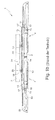
- Fig. 2 shows the bidirectional collection device 101 according to the invention , which is identical in function to the bidirectional collection device 1 of Fig. 1 is. Therefore, in Fig. 2 for functionally identical parts the same reference numbers as in Fig. 1 used.
- the bidirectional collection device 101 has no separate guide housing, but the driver 10 and the linear damper 13 of each unidirectional collection device 4 are independent of each other attached to the housing 5.
- the housing 5 has two housing halves, of which in Fig. 2 the upper one is removed and therefore only the lower one is visible.
- the two housing halves have, in addition to the guides 7 for the coupling slide 6 and the guides 9 for the driver 10 and also trough-shaped receptacles (not shown), in which the linear damper 13 is inserted and thereby secured in the housing 5.
- the coupling carriages 6 are each slidably and tiltably guided by means of their two projecting two guide pins 16, 17 and the drivers 10 by means of their two projecting two guide pins 101, 102 on both sides.
- the two drivers 10 are connected by the pull-in spring 12 with each other and thereby acted upon in their retracted end position.
- each of the two unidirectional collection devices 4 can be on the same housing 5 for each of the two unidirectional collection devices 4 either one or more, z. B. as present two parallel linear damper 13 are attached.
- the driver 10 is in two parts of a guide member 103 and a pivotally mounted thereon tilting 104 formed.
- the guide element 103 has the elongated guide pin 101 protruding on both sides, with which it is guided linearly displaceably in the straight guide section 9a of the guide track 9.
- the tilting element 104 has the circular guide pin 102 protruding on both sides, with which it can be tilted linearly in the straight guide section 9a of the guide track 9 and then tilted into the locking end position in the transverse guide section 9b is guided.
- the guide element 103 has a bearing journal 105 and the tilting element 104 has a bearing receptacle 106 rotatably mounted on the bearing journal 105.
- the linear damper 13 are formed as a piston damper with piston rod 107 , which are respectively inserted into a blind bore 108 of the guide member 103 and thus both act on the guide member 103.
- the two-part design of the driver 10 has the advantage that the forces acting on the guide member 103 damping forces of the linear damper or 13 have no influence on the tilting movement of the tilting element 104.
Abstract
Description
Die Erfindung betrifft eine bidirektionale Einzugsvorrichtung zum beidseitigen Einziehen einer Schiebetür in eine Mitteltürstellung gemäß Oberbegriff von Anspruch 1, sowie eine Schiebetüranordnung mit einer solchen bidirektionalen Einzugsvorrichtung.The invention relates to a bidirectional intake device for pulling a sliding door on both sides into a middle door position according to the preamble of
Eine derartige bidirektionale Einzugsvorrichtung ist beispielsweise durch
Unidirektionale Einzugsvorrichtungen zum Einziehen eines verschiebbaren Möbelteils, wie z.B. einer Schublade oder einer Schiebetür, in ihre geschlossene Endstellung sind allgemein bekannt. Solche bekannten unidirektionalen Einzugsvorrichtungen weisen einen verschiebbar geführten Mitnehmer zum lösbaren Koppeln mit dem Möbelteil auf. Das Möbelteil ist in seiner geschlossenen Endstellung im Eingriff mit dem eingezogenen Mitnehmer und nimmt bei seiner Offnungsbewegung den Mitnehmer aus einer eingezogenen Endstellung gegen die Wirkung einer Einzugsfeder in eine verkippte Verriegelungsendstellung mit, in der das Möbelteil in Öffnungsrichtung vom Mitnehmer entkoppelt ist. Bei seiner Schließbewegung löst das Möbelteil den Mitnehmer aus der Verriegelungsendstellung und wird von diesem, angetrieben von der Einzugsfeder, bis in die geschlossene Endstellung eingezogen.Unidirectional collection devices for drawing in a movable furniture part, such as e.g. a drawer or a sliding door, in its closed end position are well known. Such known unidirectional intake devices have a slidably guided driver for releasable coupling with the furniture part. The furniture part is in its closed end position in engagement with the retracted driver and takes in its opening movement the driver from a retracted end position against the action of a catch spring in a tilted locking end position, in which the furniture part is decoupled in the opening direction of the driver. During its closing movement, the furniture part releases the driver from the locking end position and is retracted therefrom, driven by the pull-in spring, into the closed end position.
Die aus der
Es die Aufgabe der vorliegenden Erfindung, eine solche bidirektionale Einzugsvorrichtung zum beidseitigen Einziehen einer Schiebetür in die Mitteltürstellung weiter zu verbessern.It is the object of the present invention to further improve such a bidirectional intake device for double-sided pulling a sliding door into the middle door position.
Diese Aufgabe wird erfindungsgemäß dadurch gelöst, dass das Gehäuse auch die Führungen für die Mitnehmer aufweist und dass die Lineardämpfer unabhängig von den Mitnehmern am Gehäuse befestigbar sind.This object is achieved in that the housing also has the guides for the driver and that the linear damper independently of the drivers on the housing can be fastened.
Im Vergleich zu den bekannten separaten Führungsgehäusen der unidirektionalen Einzugsvorrichtungen wird erfindungsgemäß eine baulich kleinere Einheit ermöglicht. Außerdem bietet der befestigbare Lineardämpfer die Möglichkeit, aus mehreren Lineardämpfern mit jeweils unterschiedlichen Dämpfungscharakteristiken den jeweils optimalen Lineardämpfer auszuwählen und einzubauen.Compared to the known separate guide housings of the unidirectional feeders, a structurally smaller unit is made possible according to the invention. In addition, the attachable linear damper offers the possibility of selecting and installing the optimum linear damper from several linear dampers, each with different damping characteristics.
Besonders bevorzugt sind am gleichen Gehäuse für jede der beiden unidirektionalen Einzugseinrichtungen wahlweise ein einziger Lineardämpfer oder mehrere parallele Lineardämpfer befestigbar, um so je nach Gewichtsklasse der Schiebetür die entsprechende Dämpfungscharakteristik zu erzeugen.Particularly preferred are on the same housing for each of the two unidirectional collection devices optionally a single linear damper or more parallel linear damper fastened so as to produce the corresponding damping characteristic depending on the weight class of the sliding door.
Bei einer bevorzugten Ausführungsform der Erfindung ist der Mitnehmer zweiteilig gebildet, nämlich aus einem in der Führung des Gehäuses linear geführten Führungselement und einem in der Führung des Gehäuses linear und verkippbar geführten Kippelement, das am Führungselement schwenkbar gelagert ist. Diese zweiteilige Ausbildung des Mitnehmers hat den Vorteil, dass die Dämpfungskräfte des bzw. der Lineardämpfer keinen Einfluss auf die Kippbewegung des Mitnehmers haben. In einer vorteilhaften Weiterbildung dieser Ausführungsform weist das Führungselement einen Lagerzapfen und das Kippelement eine auf dem Lagerzapfen drehbar gelagerte Lageraufnahme auf, oder umgekehrt.In a preferred embodiment of the invention, the driver is formed in two parts, namely from a linearly guided in the leadership of the housing guide member and a guided in the leadership of the housing linear and tiltable tilting element which is pivotally mounted on the guide element. This two-part design of the driver has the advantage that the damping forces of the linear damper or have no effect on the tilting movement of the driver. In an advantageous development of this embodiment, the guide element has a bearing journal and the tilting element has a bearing receptacle rotatably mounted on the bearing journal, or vice versa.
In den Rahmen der Erfindung fällt auch eine Schiebetüranordnung mit einer Schiebetür und mit einer wie oben beschriebenen bidirektionalen Einzugsvorrichtung, wobei die Schiebetür in ihrer Mitteltürstellung in beide Richtungen mit dem Schlitten bewegungsgekoppelt ist.The scope of the invention also includes a sliding door arrangement with a sliding door and with a bidirectional draw-in device as described above, the sliding door being motion-coupled with the slide in its middle door position in both directions.
Weitere Vorteile der Erfindung ergeben sich aus der Beschreibung, den Ansprüchen und der Zeichnung. Ebenso können die vorstehend genannten und die noch weiter aufgeführten Merkmale je für sich oder zu mehreren in beliebigen Kombinationen Verwendung finden. Die gezeigte und beschriebene Ausführungsform ist nicht als abschließende Aufzählung zu verstehen, sondern hat vielmehr beispielhaften Charakter für die Schilderung der Erfindung.Further advantages of the invention will become apparent from the description, the claims and the drawings. Likewise, the features mentioned above and the features listed further can be used individually or in combination in any combination. The embodiment shown and described is not to be understood as an exhaustive list, but rather has exemplary character for the description of the invention.
Es zeigen:
- Fign. 1a-1c
- eine bekannte bidirektionale Einzugsvorrichtung in einer Mitteistellung (
Fig. 1a ), in der eine Schiebetür in ihre Mitteltürstellung eingezogen ist, in einer Zwischenstellung (Fig. 1 b) , in der die in Öffnungsrichtung aus der Mitteltürstellung verschobene Schiebetür in Öffnungsrichtung noch mit der Einzugsvorrichtung bewegungsgekoppelt ist, und in einer Endstellung (Fig. 1c ), in der die in Öffnungsrichtung aus der Mitteltürstellung verschobene Schiebetür in Öffnungsrichtung nicht mehr mit der Einzugsvorrichtung bewegungsgekoppelt ist; - Fig. 2
- die erfindungsgemäße bidirektionale Einzugsvorrichtung in einer Mittelstellung analog zu
Fig. 1 a , mit abgenommener oberer Gehäuse-hälfte; und - Fign. 3a, 3b
- jeweils Detailansichten eines in
Fig. 2 gezeigten Führungselements (Fig. 3a ) und eines am Führungselement verkippbar gelagerten Kipp-elements (Fig. 3b ).
- FIGS. 1a-1c
- a known bidirectional collection device in a Mitteistellung (
Fig. 1a ), in which a sliding door is retracted into its middle door position, in an intermediate position (Fig. 1 b) in which the sliding door, which has been displaced out of the middle door position in the opening direction, is still motion-coupled in the opening direction with the draw-in device is, and in an end position (Fig. 1c ), in which the sliding in the opening direction from the middle door position sliding door in the opening direction is no longer movement coupled to the retraction device; - Fig. 2
- the bidirectional intake device according to the invention in a middle position analogous to
Fig. 1 a , with removed upper housing half; and - FIGS. 3a, 3b
- each detail views of a in
Fig. 2 shown guide element (Fig. 3a ) and a tilting element mounted on the guide element (Fig. 3b ).
Die in
Die Einzugsvorrichtung 1 umfasst zwei in entgegengesetzte Richtungen wirksame unidirektionale Einzugseinrichtungen 4, die im gezeigten Ausführungsbeispiel identisch ausgebildet und spiegelbildlich zueinander in ein Gehäuse 5 eingebaut sind, sowie einen Kopplungsschlitten 6, der in seitlichen Führungen (z.B. Führungsnuten) 7 des Gehäuses 5 in Richtung des Doppelpfeils 2 verschiebbar geführt ist. Der Kopplungsschlitten 6 ist zwischen der Schiebetür 3 und den Einzugseinrichtungen 4 angeordnet und dient, wie unten noch im Detail beschrieben, zum Koppeln der Schiebetür 3 mit den Einzugseinrichtungen 4.The
Jede Einzugseinrichtung 4 weist ein Führungsgehäuse 8 mit einer Führungsbahn 9 auf, in der ein schlittenförmiger Mitnehmer 10 zwischen einer eingezogenen und einer ausgezogenen Endstellung verschiebbar geführt ist. In
Der Kopplungsschlitten 6 weist einen mittleren Schlittenarm 14 und zwei äußere Schlittenarme 15 auf, welche am mittleren Schlittenarm 14 jeweils über Achsen 16 angelenkt, also kippbeweglich verbunden sind. Über diese Achsen 16, die seitlich über den Kopplungsschlitten 6 überstehen, ist der mittlere Schlittenarm 14 in den seitlichen Führungen 7 des Gehäuses 5 geführt. Die freien Enden der äußeren Schlittenarme 15 sind über Führungszapfen 17 ebenfalls in den seitlichen Führungen 7 geführt. Die äußeren Schlittenarme 15 weisen jeweils an ihrer dem Mitnehmer 10 zugewandten Seite einen Vorsprung 18 und an ihrer der Schiebetür 3 zugewandten Seite ein vorstehendes Kopplungselement 19 auf, das wie gezeigt beispielsweise durch einen schräg vorstehenden Arm gebildet sein kann.The
An einen geraden mittleren Führungsabschnitt 20 der Führung 7 schließen sich jeweils über einen schrägen Führungsabschnitt 21 (
Die Schiebetür 3 weist an ihrer dem Kopplungsschlitten 6 zugewandten Seite zwei Mitnehmervorsprünge 23 auf, deren Außenabstand dem Abstand der beiden Kopplungselemente 19 entspricht. Die Mitnehmervorsprünge 23 können beispielsweise durch einen Bolzen oder ein abgewinkeltes Blech gebildet sein.The sliding
In
Wenn die Schiebetür 3 aus ihrer in
Wenn die Schiebetür 3 und damit der Kopplungsschlitten 6 noch weiter nach links geschoben werden, wird der Mitnehmer 10 der linken Einzugseinrichtung 4 gegen die Wirkung der Einzugsfeder 12 weiter nach links geschoben, bis er schließlich am Ende des geraden Führungsabschnitts 9a über den quer verlaufenden Führungsabschnitt 9b in eine Verriegelungsendstellung verkippt. In dieser Verriegelungsendstellung ist die Aussparung 11 des Mitnehmers 10 zur Öffnungsrichtung 24 hin offen, so dass der linke Schlittenarm 15 in Öffnungsrichtung 24 vom Mitnehmer 10 entkoppelt ist.If the sliding
Die in
Wird die Schiebetür 3 ausgehend von
Im Unterschied zu der bidirektionalen Einzugsvorrichtung 1, bei welcher der Mitnehmer 10 und der Lineardämpfer 13 jeder unidirektionalen Einzugseinrichtung 4 in einem separaten Führungsgehäuse 8 angeordnet sind, weist die bidirektionale Einzugsvorrichtung 101 keine separaten Führungsgehäuse auf, sondern der Mitnehmer 10 und der Lineardämpfer 13 jeder unidirektionalen Einzugseinrichtung 4 sind voneinander unabhängig am Gehäuse 5 befestigt. Das Gehäuse 5 weist zwei Gehäusehälften auf, von denen in
Je nach Gewichtsklasse der Schiebetür 3, können am gleichen Gehäuse 5 für jede der beiden unidirektionalen Einzugseinrichtungen 4 wahlweise ein oder mehrere, z. B. wie vorliegend zwei, parallele Lineardämpfer 13 befestigt werden.Depending on the weight class of the sliding
Wie in
Wie in
Claims (11)
Priority Applications (2)
| Application Number | Priority Date | Filing Date | Title |
|---|---|---|---|
| SI201330779T SI2730734T1 (en) | 2012-11-13 | 2013-10-07 | Bidirectional retraction device for a middle sliding door |
| PL13187575T PL2730734T3 (en) | 2012-11-13 | 2013-10-07 | Bidirectional retraction device for a middle sliding door |
Applications Claiming Priority (1)
| Application Number | Priority Date | Filing Date | Title |
|---|---|---|---|
| DE202012104360U DE202012104360U1 (en) | 2012-11-13 | 2012-11-13 | Bidirectional feeder for a middle sliding door |
Publications (3)
| Publication Number | Publication Date |
|---|---|
| EP2730734A2 true EP2730734A2 (en) | 2014-05-14 |
| EP2730734A3 EP2730734A3 (en) | 2016-07-13 |
| EP2730734B1 EP2730734B1 (en) | 2017-09-13 |
Family
ID=47427054
Family Applications (1)
| Application Number | Title | Priority Date | Filing Date |
|---|---|---|---|
| EP13187575.9A Active EP2730734B1 (en) | 2012-11-13 | 2013-10-07 | Bidirectional retraction device for a middle sliding door |
Country Status (6)
| Country | Link |
|---|---|
| EP (1) | EP2730734B1 (en) |
| DE (1) | DE202012104360U1 (en) |
| DK (1) | DK2730734T3 (en) |
| ES (1) | ES2651680T3 (en) |
| PL (1) | PL2730734T3 (en) |
| SI (1) | SI2730734T1 (en) |
Cited By (2)
| Publication number | Priority date | Publication date | Assignee | Title |
|---|---|---|---|---|
| CN105507721A (en) * | 2016-01-19 | 2016-04-20 | 许姜德 | Bi-directional damper device |
| EP3581746A1 (en) * | 2018-06-12 | 2019-12-18 | Günther Zimmer | Combined damping and pulling device for a middle door |
Families Citing this family (3)
| Publication number | Priority date | Publication date | Assignee | Title |
|---|---|---|---|---|
| DE102014103074B4 (en) * | 2014-03-07 | 2016-06-30 | Carl Stahl Kromer Gmbh | Sliding part with spring tension |
| DE102016007885A1 (en) * | 2016-06-29 | 2018-01-04 | Günther Zimmer | Center door closing device with transfer carriage |
| DE102018122289A1 (en) * | 2018-09-12 | 2020-03-12 | Hettich-Oni Gmbh & Co. Kg | Device for mechanically closing a movable furniture part and method for opening and closing a movable furniture part |
Citations (1)
| Publication number | Priority date | Publication date | Assignee | Title |
|---|---|---|---|---|
| DE202010007230U1 (en) | 2010-05-27 | 2010-08-26 | Häfele GmbH & Co. KG | Bidirectional feeder for a middle sliding door |
Family Cites Families (3)
| Publication number | Priority date | Publication date | Assignee | Title |
|---|---|---|---|---|
| WO2007111424A1 (en) * | 2006-03-27 | 2007-10-04 | Yoon Sik Park | Self closing means |
| DE102008009046B4 (en) * | 2008-02-13 | 2014-10-02 | Günther Zimmer | Acceleration and deceleration device with two driving elements |
| DE102011001749A1 (en) * | 2011-04-01 | 2012-10-04 | Karl Simon Gmbh & Co. Kg | retraction device |
-
2012
- 2012-11-13 DE DE202012104360U patent/DE202012104360U1/en not_active Expired - Lifetime
-
2013
- 2013-10-07 PL PL13187575T patent/PL2730734T3/en unknown
- 2013-10-07 ES ES13187575.9T patent/ES2651680T3/en active Active
- 2013-10-07 SI SI201330779T patent/SI2730734T1/en unknown
- 2013-10-07 DK DK13187575.9T patent/DK2730734T3/en active
- 2013-10-07 EP EP13187575.9A patent/EP2730734B1/en active Active
Patent Citations (1)
| Publication number | Priority date | Publication date | Assignee | Title |
|---|---|---|---|---|
| DE202010007230U1 (en) | 2010-05-27 | 2010-08-26 | Häfele GmbH & Co. KG | Bidirectional feeder for a middle sliding door |
Cited By (3)
| Publication number | Priority date | Publication date | Assignee | Title |
|---|---|---|---|---|
| CN105507721A (en) * | 2016-01-19 | 2016-04-20 | 许姜德 | Bi-directional damper device |
| CN105507721B (en) * | 2016-01-19 | 2017-06-27 | 许姜德 | A kind of two way damper device |
| EP3581746A1 (en) * | 2018-06-12 | 2019-12-18 | Günther Zimmer | Combined damping and pulling device for a middle door |
Also Published As
| Publication number | Publication date |
|---|---|
| DK2730734T3 (en) | 2017-12-18 |
| SI2730734T1 (en) | 2017-12-29 |
| ES2651680T3 (en) | 2018-01-29 |
| DE202012104360U1 (en) | 2012-11-21 |
| PL2730734T3 (en) | 2018-02-28 |
| EP2730734B1 (en) | 2017-09-13 |
| EP2730734A3 (en) | 2016-07-13 |
Similar Documents
| Publication | Publication Date | Title |
|---|---|---|
| EP2001327B1 (en) | Drive mechanism for a furniture part which is mounted movably in or on an item of furniture | |
| EP2661195B1 (en) | Lockable ejection device with overload mechanism | |
| EP2390448B1 (en) | Bidirectional retracting device for a middle sliding door | |
| EP3087866B1 (en) | Fitting for a corner cupboard and corner cupboard with fitting | |
| EP3088646B1 (en) | Guide device for a sliding door | |
| EP3084107B1 (en) | Damping unit for a sliding element | |
| EP1120066A2 (en) | Closure and/or retraction device for moving furniture parts | |
| EP2488718B1 (en) | Automatic retraction and damping device | |
| EP2353445B2 (en) | Slide for retracting parts of furniture | |
| DE202008016409U1 (en) | Self-closing device and pullout guide | |
| EP1817983A1 (en) | Device for influencing the movement of furniture parts moving relative to one another and a drawer guide, as well as a method of producing such a device | |
| EP2730734B1 (en) | Bidirectional retraction device for a middle sliding door | |
| EP2956032B1 (en) | Drawer guide for a movable furniture part | |
| EP1743550A1 (en) | Displacement device for furniture extensions, in particular drawers | |
| EP2758618B1 (en) | Movable mounting plate for furniture hinges | |
| DE202017100244U1 (en) | Shower partition with a by a spring-damper unit active in the end positions movable sliding door | |
| DE102007059575A1 (en) | Damping and moving device for sliding element i.e. sliding door, has damping cylinders arranged one above other, where tension springs and damping cylinders are arranged in series connection with one behind other | |
| WO2012038339A1 (en) | Automatic retraction apparatus for a movable furniture part | |
| EP3142516B1 (en) | Retracting device for furniture | |
| EP2992156B1 (en) | Guiding assembly of a sliding door, a sliding door and a piece of furniture | |
| WO2012175548A1 (en) | Internal 180-degree hinge for an arrangement of cabinets in a row | |
| DE102018100674A1 (en) | Furniture panel with a hinge and furniture with such a furniture panel | |
| EP1384420B1 (en) | Damped self closing mechanism | |
| EP3296492A1 (en) | Guide system for a push door and push door with a guide system and motor vehicle with corresponding feature | |
| DE202012002884U1 (en) | damper system |
Legal Events
| Date | Code | Title | Description |
|---|---|---|---|
| PUAI | Public reference made under article 153(3) epc to a published international application that has entered the european phase |
Free format text: ORIGINAL CODE: 0009012 |
|
| 17P | Request for examination filed |
Effective date: 20131007 |
|
| AK | Designated contracting states |
Kind code of ref document: A2 Designated state(s): AL AT BE BG CH CY CZ DE DK EE ES FI FR GB GR HR HU IE IS IT LI LT LU LV MC MK MT NL NO PL PT RO RS SE SI SK SM TR |
|
| AX | Request for extension of the european patent |
Extension state: BA ME |
|
| PUAL | Search report despatched |
Free format text: ORIGINAL CODE: 0009013 |
|
| AK | Designated contracting states |
Kind code of ref document: A3 Designated state(s): AL AT BE BG CH CY CZ DE DK EE ES FI FR GB GR HR HU IE IS IT LI LT LU LV MC MK MT NL NO PL PT RO RS SE SI SK SM TR |
|
| AX | Request for extension of the european patent |
Extension state: BA ME |
|
| RIC1 | Information provided on ipc code assigned before grant |
Ipc: E05F 1/16 20060101ALI20160608BHEP Ipc: E05F 5/00 20060101AFI20160608BHEP |
|
| R17P | Request for examination filed (corrected) |
Effective date: 20160714 |
|
| RBV | Designated contracting states (corrected) |
Designated state(s): AL AT BE BG CH CY CZ DE DK EE ES FI FR GB GR HR HU IE IS IT LI LT LU LV MC MK MT NL NO PL PT RO RS SE SI SK SM TR |
|
| GRAP | Despatch of communication of intention to grant a patent |
Free format text: ORIGINAL CODE: EPIDOSNIGR1 |
|
| INTG | Intention to grant announced |
Effective date: 20170425 |
|
| GRAS | Grant fee paid |
Free format text: ORIGINAL CODE: EPIDOSNIGR3 |
|
| GRAA | (expected) grant |
Free format text: ORIGINAL CODE: 0009210 |
|
| AK | Designated contracting states |
Kind code of ref document: B1 Designated state(s): AL AT BE BG CH CY CZ DE DK EE ES FI FR GB GR HR HU IE IS IT LI LT LU LV MC MK MT NL NO PL PT RO RS SE SI SK SM TR |
|
| REG | Reference to a national code |
Ref country code: GB Ref legal event code: FG4D Free format text: NOT ENGLISH |
|
| REG | Reference to a national code |
Ref country code: CH Ref legal event code: EP |
|
| REG | Reference to a national code |
Ref country code: IE Ref legal event code: FG4D Free format text: LANGUAGE OF EP DOCUMENT: GERMAN |
|
| REG | Reference to a national code |
Ref country code: AT Ref legal event code: REF Ref document number: 928329 Country of ref document: AT Kind code of ref document: T Effective date: 20171015 |
|
| REG | Reference to a national code |
Ref country code: DE Ref legal event code: R096 Ref document number: 502013008329 Country of ref document: DE Ref country code: FR Ref legal event code: PLFP Year of fee payment: 5 |
|
| REG | Reference to a national code |
Ref country code: SE Ref legal event code: TRGR |
|
| REG | Reference to a national code |
Ref country code: DK Ref legal event code: T3 Effective date: 20171213 |
|
| REG | Reference to a national code |
Ref country code: NL Ref legal event code: FP |
|
| REG | Reference to a national code |
Ref country code: LT Ref legal event code: MG4D |
|
| REG | Reference to a national code |
Ref country code: ES Ref legal event code: FG2A Ref document number: 2651680 Country of ref document: ES Kind code of ref document: T3 Effective date: 20180129 |
|
| PG25 | Lapsed in a contracting state [announced via postgrant information from national office to epo] |
Ref country code: HR Free format text: LAPSE BECAUSE OF FAILURE TO SUBMIT A TRANSLATION OF THE DESCRIPTION OR TO PAY THE FEE WITHIN THE PRESCRIBED TIME-LIMIT Effective date: 20170913 Ref country code: NO Free format text: LAPSE BECAUSE OF FAILURE TO SUBMIT A TRANSLATION OF THE DESCRIPTION OR TO PAY THE FEE WITHIN THE PRESCRIBED TIME-LIMIT Effective date: 20171213 Ref country code: FI Free format text: LAPSE BECAUSE OF FAILURE TO SUBMIT A TRANSLATION OF THE DESCRIPTION OR TO PAY THE FEE WITHIN THE PRESCRIBED TIME-LIMIT Effective date: 20170913 Ref country code: LT Free format text: LAPSE BECAUSE OF FAILURE TO SUBMIT A TRANSLATION OF THE DESCRIPTION OR TO PAY THE FEE WITHIN THE PRESCRIBED TIME-LIMIT Effective date: 20170913 |
|
| PG25 | Lapsed in a contracting state [announced via postgrant information from national office to epo] |
Ref country code: GR Free format text: LAPSE BECAUSE OF FAILURE TO SUBMIT A TRANSLATION OF THE DESCRIPTION OR TO PAY THE FEE WITHIN THE PRESCRIBED TIME-LIMIT Effective date: 20171214 Ref country code: RS Free format text: LAPSE BECAUSE OF FAILURE TO SUBMIT A TRANSLATION OF THE DESCRIPTION OR TO PAY THE FEE WITHIN THE PRESCRIBED TIME-LIMIT Effective date: 20170913 Ref country code: BG Free format text: LAPSE BECAUSE OF FAILURE TO SUBMIT A TRANSLATION OF THE DESCRIPTION OR TO PAY THE FEE WITHIN THE PRESCRIBED TIME-LIMIT Effective date: 20171213 Ref country code: LV Free format text: LAPSE BECAUSE OF FAILURE TO SUBMIT A TRANSLATION OF THE DESCRIPTION OR TO PAY THE FEE WITHIN THE PRESCRIBED TIME-LIMIT Effective date: 20170913 |
|
| PG25 | Lapsed in a contracting state [announced via postgrant information from national office to epo] |
Ref country code: CZ Free format text: LAPSE BECAUSE OF FAILURE TO SUBMIT A TRANSLATION OF THE DESCRIPTION OR TO PAY THE FEE WITHIN THE PRESCRIBED TIME-LIMIT Effective date: 20170913 Ref country code: RO Free format text: LAPSE BECAUSE OF FAILURE TO SUBMIT A TRANSLATION OF THE DESCRIPTION OR TO PAY THE FEE WITHIN THE PRESCRIBED TIME-LIMIT Effective date: 20170913 |
|
| PG25 | Lapsed in a contracting state [announced via postgrant information from national office to epo] |
Ref country code: SM Free format text: LAPSE BECAUSE OF FAILURE TO SUBMIT A TRANSLATION OF THE DESCRIPTION OR TO PAY THE FEE WITHIN THE PRESCRIBED TIME-LIMIT Effective date: 20170913 Ref country code: SK Free format text: LAPSE BECAUSE OF FAILURE TO SUBMIT A TRANSLATION OF THE DESCRIPTION OR TO PAY THE FEE WITHIN THE PRESCRIBED TIME-LIMIT Effective date: 20170913 Ref country code: EE Free format text: LAPSE BECAUSE OF FAILURE TO SUBMIT A TRANSLATION OF THE DESCRIPTION OR TO PAY THE FEE WITHIN THE PRESCRIBED TIME-LIMIT Effective date: 20170913 Ref country code: IS Free format text: LAPSE BECAUSE OF FAILURE TO SUBMIT A TRANSLATION OF THE DESCRIPTION OR TO PAY THE FEE WITHIN THE PRESCRIBED TIME-LIMIT Effective date: 20180113 |
|
| REG | Reference to a national code |
Ref country code: CH Ref legal event code: PL |
|
| REG | Reference to a national code |
Ref country code: DE Ref legal event code: R097 Ref document number: 502013008329 Country of ref document: DE |
|
| PG25 | Lapsed in a contracting state [announced via postgrant information from national office to epo] |
Ref country code: MC Free format text: LAPSE BECAUSE OF FAILURE TO SUBMIT A TRANSLATION OF THE DESCRIPTION OR TO PAY THE FEE WITHIN THE PRESCRIBED TIME-LIMIT Effective date: 20170913 |
|
| PLBE | No opposition filed within time limit |
Free format text: ORIGINAL CODE: 0009261 |
|
| STAA | Information on the status of an ep patent application or granted ep patent |
Free format text: STATUS: NO OPPOSITION FILED WITHIN TIME LIMIT |
|
| REG | Reference to a national code |
Ref country code: IE Ref legal event code: MM4A |
|
| PG25 | Lapsed in a contracting state [announced via postgrant information from national office to epo] |
Ref country code: LI Free format text: LAPSE BECAUSE OF NON-PAYMENT OF DUE FEES Effective date: 20171031 Ref country code: LU Free format text: LAPSE BECAUSE OF NON-PAYMENT OF DUE FEES Effective date: 20171007 Ref country code: CH Free format text: LAPSE BECAUSE OF NON-PAYMENT OF DUE FEES Effective date: 20171031 |
|
| 26N | No opposition filed |
Effective date: 20180614 |
|
| REG | Reference to a national code |
Ref country code: BE Ref legal event code: MM Effective date: 20171031 |
|
| PG25 | Lapsed in a contracting state [announced via postgrant information from national office to epo] |
Ref country code: BE Free format text: LAPSE BECAUSE OF NON-PAYMENT OF DUE FEES Effective date: 20171031 |
|
| PG25 | Lapsed in a contracting state [announced via postgrant information from national office to epo] |
Ref country code: MT Free format text: LAPSE BECAUSE OF FAILURE TO SUBMIT A TRANSLATION OF THE DESCRIPTION OR TO PAY THE FEE WITHIN THE PRESCRIBED TIME-LIMIT Effective date: 20170913 |
|
| REG | Reference to a national code |
Ref country code: FR Ref legal event code: PLFP Year of fee payment: 6 |
|
| PG25 | Lapsed in a contracting state [announced via postgrant information from national office to epo] |
Ref country code: IE Free format text: LAPSE BECAUSE OF NON-PAYMENT OF DUE FEES Effective date: 20171007 |
|
| PG25 | Lapsed in a contracting state [announced via postgrant information from national office to epo] |
Ref country code: HU Free format text: LAPSE BECAUSE OF FAILURE TO SUBMIT A TRANSLATION OF THE DESCRIPTION OR TO PAY THE FEE WITHIN THE PRESCRIBED TIME-LIMIT; INVALID AB INITIO Effective date: 20131007 |
|
| PG25 | Lapsed in a contracting state [announced via postgrant information from national office to epo] |
Ref country code: CY Free format text: LAPSE BECAUSE OF NON-PAYMENT OF DUE FEES Effective date: 20170913 |
|
| PG25 | Lapsed in a contracting state [announced via postgrant information from national office to epo] |
Ref country code: MK Free format text: LAPSE BECAUSE OF FAILURE TO SUBMIT A TRANSLATION OF THE DESCRIPTION OR TO PAY THE FEE WITHIN THE PRESCRIBED TIME-LIMIT Effective date: 20170913 |
|
| REG | Reference to a national code |
Ref country code: AT Ref legal event code: MM01 Ref document number: 928329 Country of ref document: AT Kind code of ref document: T Effective date: 20181007 |
|
| PG25 | Lapsed in a contracting state [announced via postgrant information from national office to epo] |
Ref country code: AT Free format text: LAPSE BECAUSE OF NON-PAYMENT OF DUE FEES Effective date: 20181007 |
|
| PG25 | Lapsed in a contracting state [announced via postgrant information from national office to epo] |
Ref country code: PT Free format text: LAPSE BECAUSE OF FAILURE TO SUBMIT A TRANSLATION OF THE DESCRIPTION OR TO PAY THE FEE WITHIN THE PRESCRIBED TIME-LIMIT Effective date: 20170913 |
|
| PG25 | Lapsed in a contracting state [announced via postgrant information from national office to epo] |
Ref country code: AL Free format text: LAPSE BECAUSE OF FAILURE TO SUBMIT A TRANSLATION OF THE DESCRIPTION OR TO PAY THE FEE WITHIN THE PRESCRIBED TIME-LIMIT Effective date: 20170913 |
|
| P01 | Opt-out of the competence of the unified patent court (upc) registered |
Effective date: 20230630 |
|
| PGFP | Annual fee paid to national office [announced via postgrant information from national office to epo] |
Ref country code: TR Payment date: 20230929 Year of fee payment: 11 |
|
| PGFP | Annual fee paid to national office [announced via postgrant information from national office to epo] |
Ref country code: PL Payment date: 20230818 Year of fee payment: 11 Ref country code: NL Payment date: 20231023 Year of fee payment: 11 |
|
| PGFP | Annual fee paid to national office [announced via postgrant information from national office to epo] |
Ref country code: GB Payment date: 20231025 Year of fee payment: 11 |
|
| PGFP | Annual fee paid to national office [announced via postgrant information from national office to epo] |
Ref country code: ES Payment date: 20231117 Year of fee payment: 11 |
|
| PGFP | Annual fee paid to national office [announced via postgrant information from national office to epo] |
Ref country code: SI Payment date: 20230926 Year of fee payment: 11 Ref country code: SE Payment date: 20231025 Year of fee payment: 11 Ref country code: IT Payment date: 20231031 Year of fee payment: 11 Ref country code: FR Payment date: 20231023 Year of fee payment: 11 Ref country code: DK Payment date: 20231025 Year of fee payment: 11 Ref country code: DE Payment date: 20231024 Year of fee payment: 11 |