EP2727716B1 - Vorrichtung zum Nuten von Pappenzuschnitten - Google Patents
Vorrichtung zum Nuten von Pappenzuschnitten Download PDFInfo
- Publication number
- EP2727716B1 EP2727716B1 EP20130004270 EP13004270A EP2727716B1 EP 2727716 B1 EP2727716 B1 EP 2727716B1 EP 20130004270 EP20130004270 EP 20130004270 EP 13004270 A EP13004270 A EP 13004270A EP 2727716 B1 EP2727716 B1 EP 2727716B1
- Authority
- EP
- European Patent Office
- Prior art keywords
- knife
- curved guide
- groove
- transport drum
- drum
- Prior art date
- Legal status (The legal status is an assumption and is not a legal conclusion. Google has not performed a legal analysis and makes no representation as to the accuracy of the status listed.)
- Active
Links
Images

Classifications
-
- B—PERFORMING OPERATIONS; TRANSPORTING
- B26—HAND CUTTING TOOLS; CUTTING; SEVERING
- B26D—CUTTING; DETAILS COMMON TO MACHINES FOR PERFORATING, PUNCHING, CUTTING-OUT, STAMPING-OUT OR SEVERING
- B26D3/00—Cutting work characterised by the nature of the cut made; Apparatus therefor
- B26D3/06—Grooving involving removal of material from the surface of the work
- B26D3/065—On sheet material
-
- B—PERFORMING OPERATIONS; TRANSPORTING
- B26—HAND CUTTING TOOLS; CUTTING; SEVERING
- B26D—CUTTING; DETAILS COMMON TO MACHINES FOR PERFORATING, PUNCHING, CUTTING-OUT, STAMPING-OUT OR SEVERING
- B26D7/00—Details of apparatus for cutting, cutting-out, stamping-out, punching, perforating, or severing by means other than cutting
- B26D2007/0012—Details, accessories or auxiliary or special operations not otherwise provided for
- B26D2007/0043—Details, accessories or auxiliary or special operations not otherwise provided for the cutting machine comprising a linear motor
-
- B—PERFORMING OPERATIONS; TRANSPORTING
- B26—HAND CUTTING TOOLS; CUTTING; SEVERING
- B26D—CUTTING; DETAILS COMMON TO MACHINES FOR PERFORATING, PUNCHING, CUTTING-OUT, STAMPING-OUT OR SEVERING
- B26D3/00—Cutting work characterised by the nature of the cut made; Apparatus therefor
- B26D3/10—Making cuts of other than simple rectilinear form
-
- B—PERFORMING OPERATIONS; TRANSPORTING
- B26—HAND CUTTING TOOLS; CUTTING; SEVERING
- B26D—CUTTING; DETAILS COMMON TO MACHINES FOR PERFORATING, PUNCHING, CUTTING-OUT, STAMPING-OUT OR SEVERING
- B26D5/00—Arrangements for operating and controlling machines or devices for cutting, cutting-out, stamping-out, punching, perforating, or severing by means other than cutting
- B26D5/08—Means for actuating the cutting member to effect the cut
- B26D5/086—Electric, magnetic, piezoelectric, electro-magnetic means
-
- B—PERFORMING OPERATIONS; TRANSPORTING
- B26—HAND CUTTING TOOLS; CUTTING; SEVERING
- B26D—CUTTING; DETAILS COMMON TO MACHINES FOR PERFORATING, PUNCHING, CUTTING-OUT, STAMPING-OUT OR SEVERING
- B26D5/00—Arrangements for operating and controlling machines or devices for cutting, cutting-out, stamping-out, punching, perforating, or severing by means other than cutting
- B26D5/08—Means for actuating the cutting member to effect the cut
- B26D5/12—Fluid-pressure means
-
- B—PERFORMING OPERATIONS; TRANSPORTING
- B31—MAKING ARTICLES OF PAPER, CARDBOARD OR MATERIAL WORKED IN A MANNER ANALOGOUS TO PAPER; WORKING PAPER, CARDBOARD OR MATERIAL WORKED IN A MANNER ANALOGOUS TO PAPER
- B31B—MAKING CONTAINERS OF PAPER, CARDBOARD OR MATERIAL WORKED IN A MANNER ANALOGOUS TO PAPER
- B31B50/00—Making rigid or semi-rigid containers, e.g. boxes or cartons
- B31B50/25—Surface scoring
-
- Y—GENERAL TAGGING OF NEW TECHNOLOGICAL DEVELOPMENTS; GENERAL TAGGING OF CROSS-SECTIONAL TECHNOLOGIES SPANNING OVER SEVERAL SECTIONS OF THE IPC; TECHNICAL SUBJECTS COVERED BY FORMER USPC CROSS-REFERENCE ART COLLECTIONS [XRACs] AND DIGESTS
- Y10—TECHNICAL SUBJECTS COVERED BY FORMER USPC
- Y10T—TECHNICAL SUBJECTS COVERED BY FORMER US CLASSIFICATION
- Y10T83/00—Cutting
- Y10T83/02—Other than completely through work thickness
- Y10T83/0304—Grooving
Definitions
- the present invention relates to a device for grooving cardboard blank according to the preamble of claim 1.
- triangular grooves are cut in cardboard blank.
- the opening angle, also referred to as the groove angle, between the two groove flanks is determined by the board thickness, the board material and, if applicable, the one or two-sided cover, and by the function of the cut groove on the box produced from the cardboard blank.
- a generic cardboard groove machine is from the CN 101200091 B known.
- the Nutenschneidwerkmaschinee are axially adjustable mounted on parallel to the transport drum support beams. They each have two at a fixed angle obliquely to each other attached to a blade holder knife. The change in the groove angle is effected by a time-consuming replacement of the respective blade receptacles against those with a different angular position of the knife. Due to the changed blade positions also arranged in each case before or after the Nutenschneidtechnikmaschineen arranged Poppenniederhalter and Spanabweiser.
- the cardboard groove machine shown is the support beam with the Nutenschneidwerkmaschineen about an axially parallel axis in the region of the drum circumference pivotable.
- the angle of the Nutenschneidtechnikmaschinee can be adjusted by a running approximately through the cutting tips of their knife pivot axis to the transport drum, which can be their common cutting angle or the resulting groove angle change together.
- the adjustment effort for the Pappenniederhalter and Spanabweiser but remains and mutually independently set groove angles are not possible.
- the object of the present invention is to provide a paperboard machine according to the preamble of claim 1, which allows an easy-to-use and separate adjustment of the Nutenschneidtechnikmaschinee and its periphery.
- the blade holder is adjustable over a present in Nutenschneidwerkmaschine sheet guide, wherein the center of curvature of the sheet guide is both in the region of the drum shell and in the region of a cutting tip of the at least one knife, can be set independently of each other at the Nutenschneidtechnikmaschineen the desired groove angle without replacing the blade receptacles become.
- the respective groove cutting tool does not have to be removed from the support beam for this purpose.
- the adjustment of the groove angle is carried out within the respective groove cutting tool, so that the support beams are rigidly arranged in the frame and can be used for other work equipment, such as Pappenniederhalter, Spanabweiser and so on.
- a pivot axis parallel to the drum rotation axis for the blade holder is defined by the sheet guide.
- a pivot axis parallel to the drum rotation axis for the blade holder is defined by the sheet guide.
- the respectively required groove angle can be adjusted quickly and reproducibly, if the blade holder and / or the bow guide have a scale with angle division, at which the resulting from certain angular positions of the knife holder groove angle can be read.
- the sheet guide is designed as a running arc in the contact surface on which the blade holder can be fixed by clamping means. Cutting forces are safely absorbed by the sheet guide and transmitted to the support bar rigidly received in the frame.
- the knife holder is designed as a removable part, worn knives can be replaced quickly and easily. Because a new knife set can be pre-assembled and aligned on a second knife holder. In addition, various, optionally usable knife shapes and arrangements can be kept ready.
- the sheet guide is received in the groove cutting tool substantially radially adjustable to the transport drum. Associated settings and adjustments to the blade holder itself are not required.
- the groove position can be corrected in the cardboard blank without the Nutenschneidwerkmaschine must be moved on the support beam.
- the deflector is designed as a chip lifter to remove possibly adhering chips in the groove.
- the deflecting plate merges into a discharge channel leading away substantially radially from the transport drum, through which the chips can be led out of the paperboard machine. With the advantage of a significantly reduced dust load, the discharge channel is connected to a disposal device for the chips.
- the cardboard blank in the region of at least one knife against the drum shell holding down pressure element in particular the leading edge of the cardboard blank is pressed against the drum shell, whereby a widening to the card edge groove is avoided.
- the pressing element holds down the cardboard blank upstream of the at least one knife in the region of the subsequently cut groove.
- the pressure element is designed as a deflector, over which shavings arising during groove cutting are derived from the transport drum.
- Fig. 1 1 schematically consists of a driven, horizontally mounted transport drum 11 and a plurality of endlessly circulating rollers 54 and spaced from each other, the transport drum 11 to form an inlet 14 and an outlet 15 partially wrapped belt 51 and between the belt 51 in one defined by a feeder 101 the inlet 14 supplied cardboard blanks 2 are conveyed by the belt 51 promoting effect on the drum shell and in the transport direction 11a in an approximately 180 ° rotation of the transport drum 11 from lying in the lower vertex of the transport drum 11 Enema 14 for lying in the upper vertex outlet 15 promoted and passed past the Nutenschneidtechnikmaschinemaschineen 72, where with appropriately shaped slot knives 71 a chip 6 with, for example, substantially triangular cross-section of the paperboard cut 2 is cut out.
- the feeder 101 in Fig. 1 has a paperboard magazine 102 containing a stack 4 of stacked cardboard blank.
- the respective lowermost cardboard blank 2 is pushed out by a first board slider 104.1 under a front stop 103 and transferred to an intermediate position 105, from which the board blank 2 is fed to the inlet 14 with a second board slider 104.2 aligned with outer guide rails 106.
- the board slides 104.1, 104.2 are coupled together at a fixed distance and are moved in a constant delivery stroke 107 equal to this distance clockwise back and forth.
- the feeding speed is equal to the rotational speed of the transport drum 11 or is slightly above it, so that the cardboard blanks 2 quasi forcibly inserted into the inlet 14 between the transport drum 11 and belt 51.
- the export 111 in Fig. 1 has an obliquely sloping forward delivery table 112 to which the expiring from the outlet 15, finished grooved cardboard cuttings 3 are dropped and stacked to stack 5. Due to the arrangement of the outlet 15 in the upper vertex of the transport drum 11, the cut grooves 3a in the leaking cardboard blank 3 are above and are thus visible to the operator.
- Fig. 1 it can be seen that the rollers 54 are arranged around the transport drum 11 such that a total of three areas form the greatest approximation of the strands lying between the rollers 54 and the belt section abutting on the transport drum 11.
- the groove cutting tools 72 may be arranged.
- the Nutenschneidtechnikmaschinee 72 are mounted on parallel to the transport drum 11 support beams 36, 37.
- Several groove cutting tools 72 may be mounted side by side.
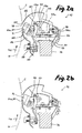
- Fig. 2a and 2b show the inventively designed Nutenschneidtechnikmaschine 72 Fig. 1 on an enlarged scale. It has a carrier 73, which can be fixed with a clamping piece 74 on the supporting beam 36. On the carrier 73 a via an eccentric 75a axially to the transport drum 11 finely adjustable carriage 75 is guided and fixable. The latter in turn carries a carriage 76, which is displaceable substantially radially relative to the transport drum 11 and can likewise be fixed by means of a knurled screw 76 a, on which the sheet guide 77 is located.
- the center of curvature 81 of the sheet guide 77 is located in the cutting tip 71 a of the groove knife 71, virtually on the circumference of the transport drum 11.
- the blade holder 78 can be adjusted to another angular position according to scale 80 (see. Fig. 2a and 2b ).
- the blade holder 78 and with it the grooving knife 71 by a through the center of curvature 81 and parallel to the transport drum 11 extending pivot axis pivoted.
- the position of the cutting tip 71 a and thus their distance from the transport drum 11 do not change.
- the depth of cut which can be set via knurled screw 76a remains constant, while due to the changed angular position of blade holder 78 on sheet guide 77, a different groove angle results.
- a Ableitblech 82 for the costs incurred in Nutenbol chips 6 the front end is positioned as chip lifter to near the cutting tip 71 a of the notch 71 and at the other end in a the Nutenschneidtechnikmaschine 72 away and substantially radially to the transport drum 11 extending discharge channel 83 merges, which can be connected to a chip disposal device not shown.
- the deflector 82 remains in its fixed position.
- a poppie-down holder 84 is provided Upstream of the grooving knife 71. It is received separately from the blade holder 78 on a arranged on the sheet guide 77 holder 87 pivotally and presses by a compression spring 85 acted upon the cardboard blank 2 in the region of the groove knife 71 against the drum shell, whereby a properly cut on the card edge groove is guaranteed.
- the pressing against the cardboard blank 2 end of the poppy lowermost 84 acts as a pressing element exclusively in the area of the subsequently cut out groove. Outside the pressure point, the poppy-down holder 84 widened to the deflecting plate 86 for chips that may possibly fall down during groove cutting.
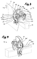
- the grooving cutter 72 is equipped with the one-piece grooved cutter 71. It is a knife with two connected to a V-shaped wings each outer ground blades 71 b, c, which are connected by a bridge to a closed ring body as chip removal channel.
- the grooving knife 71 is very easy to grind and adjust over a simple sliding seat with respect to a constant cutting tip 71a on the blade holder 78. It is not necessary to set individual knife blades to each other.
- the blades connected to the V lift the chips safely out of the groove 3a and guide them away from the cardboard blank 2 or the transport drum 11. By cutting the cutting tip 71 a can be cut with the grooving knife 71 and trapezoidal grooves.
- Fig. 4 is known from the other figures knife holder 78 with the grooved knife 71 replaced by a the same interface to the sheet guide 77 having blade holder 78 ', which is equipped with two separate blades 88 a, b.
- This also grooves 3a can be cut with a substantially triangular cross-section.
- the blade holder 78 As a removable part worn splitter blades 71 and 88 a, b can be replaced quickly.
- it can Messersonderformen and / or special knife assemblies are used to produce, for example, semi-circular cut grooves, undercut grooves such as dovetail grooves, etc. Slot and perforating knives on the groove cutting tool 72 can also be used here.
Landscapes
- Engineering & Computer Science (AREA)
- Mechanical Engineering (AREA)
- Life Sciences & Earth Sciences (AREA)
- Forests & Forestry (AREA)
- Making Paper Articles (AREA)
- Manufacturing & Machinery (AREA)
Description
- Die vorliegende Erfindung betrifft eine Vorrichtung zum Nuten von Pappenzuschnitten nach dem Oberbegriff des Anspruchs 1.
- Zur Vorbereitung von Biegestellen und insbesondere scharfkantigen Abkantungen an Schachteln werden in Pappenzuschnitten dreieckige Nuten geschnitten. Der auch als Nutwinkel bezeichnete Öffnungswinkel zwischen den beiden Nutflanken ist bestimmt nach der Pappenstärke, dem Pappenmaterial und dem ggf. ein- oder beidseitigen Bezug sowie nach der Funktion der geschnittenen Nut an der aus dem Pappenzuschnitt hergestellten Schachtel.
- Eine gattungsgemäße Pappennutmaschine ist aus der
CN 101200091 B bekannt. Die Nutenschneidwerkzeuge sind axial verstellbar auf parallel zur Transporttrommel liegenden Tragbalken montiert. Sie weisen jeweils zwei in einem festen Winkel schräg zueinander an einer Messeraufnahme befestigte Messer auf. Die Veränderung des Nutwinkels erfolgt durch einen zeitaufwendigen Austausch der jeweiligen Messeraufnahmen gegen solche mit einer anderen Winkellage der Messer. Aufgrund der veränderten Messerstellungen müssen außerdem noch jeweils vor bzw. nach den Nutenschneidwerkzeugen angeordnete Pappenniederhalter und Spanabweiser eingestellt werden. - Bei der in der
CN 201970485 U gezeigten Pappennutmaschine ist der Tragbalken mit den Nutenschneidwerkzeugen um eine im Bereich des Trommelumfangs achsparallel liegende Achse verschwenkbar. Damit lässt sich der Anstellwinkel der Nutenschneidwerkzeuge um eine in etwa durch die Schneidenspitzen ihrer Messer verlaufende Schwenkachse zur Transporttrommel verstellen, wodurch sich deren jeweilige Schneidwinkel bzw. die sich daraus ergebenen Nutwinkel gemeinsam verändern lassen. Der Einstellaufwand für die Pappenniederhalter und die Spanabweiser aber bleibt bestehen und voneinander unabhängig eingestellte Nutwinkel sind nicht möglich. - Aufgabe der vorliegenden Erfindung ist, eine Pappennutmaschine nach dem Oberbegriff des Anspruchs 1 zu schaffen, die eine bedienungsfreundliche und separate Einstellung der Nutenschneidwerkzeuge und ihrer Peripherie ermöglicht.
- Diese Aufgabe wird erfindungsgemäß durch die Merkmale des kennzeichnenden Teils des Anspruchs 1 gelöst. Bevorzugte Ausbildungsformen sind in den abhängigen Ansprüchen angegeben.
- Dadurch dass die Messeraufnahme über eine im Nutenschneidwerkzeug vorliegende Bogenführung verstellbar ist, wobei der Krümmungsmittelpunkt der Bogenführung sowohl im Bereich des Trommelmantels als auch im Bereich einer Schneidenspitze des wenigstens einen Messers liegt, kann an den Nutenschneidwerkzeugen der jeweils gewünschte Nutwinkel ohne Austausch der Messeraufnahmen unabhängig voneinander eingestellt werden. Das jeweilige Nutenschneidwerkzeug muss dafür nicht von dem Tragbalken genommen werden. Die Einstellung des Nutwinkels erfolgt innerhalb des jeweiligen Nutenschneidwerkzeugs, sodass der Tragbalken starr im Gestell angeordnet werden und für weitere Arbeitsmittel, wie Pappenniederhalter, Spanabweiser usw. genutzt werden kann. Durch einfaches und für den Bediener in seiner Auswirkung auf den Nutwinkel nachvollziehbares Verschwenken der Messeraufnahme lässt sich sehr schnell ein anderer Nutwinkel am jeweiligen Nutenschneidwerkzeug einstellen. Außerdem erfolgt die Verstellung des Nutwinkels unabhängig von der Schnitttiefe, sodass eine Abstandskorrektur des wenigstens einen Messers zur Transporttrommel entfällt. Vorzugsweise ist durch die Bogenführung eine zur Trommeldrehachse parallele Schwenkachse für die Messeraufnahme definiert.
- Wenn der Krümmungsmittelpunkt im Bereich einer Schneidenspitze des wenigstens einen Messers liegt, erfolgt die Verstellung des Nutwinkels unabhängig von der Schnitttiefe, sodass eine Abstandskorrektur des wenigstens einen Messers zur Transporttrommel entfällt. Vorzugsweise ist durch die Bogenführung eine zur Trommeldrehachse parallele Schwenkachse für die Messeraufnahme definiert.
- Der jeweils erforderliche Nutwinkel kann schnell und reproduzierbar eingestellt werden, wenn die Messeraufnahme oder/und die Bogenführung eine Skala mit Winkeleinteilung aufweisen, an der die sich aus bestimmten Winkelstellungen der Messeraufnahme ergebenen Nutwinkel abgelesen werden können.
- In konstruktiv einfacher Weise ist die Bogenführung als eine im Bogen verlaufende Anlagefläche ausgebildet, an der die Messeraufnahme durch Klemmmittel festlegbar ist. Schneidkräfte werden von der Bogenführung sicher aufgenommen und auf den im Gestell starr aufgenommenen Tragbalken übertragen.
- Wenn die Messeraufnahme als Wechselteil ausgebildet ist, können verschlissene Messer schnell und einfach ausgetauscht werden. Denn ein neuer Messersatz kann auf einer zweiten Messeraufnahme vormontiert und ausgerichtet sein. Außerdem können darüber verschiedene, wahlweise einsetzbare Messerformen und -anordnungen bereit gehalten werden.
- Mit der Möglichkeit einer Schneidtiefeneinstellung ist die Bogenführung im Wesentlichen radial zur Transporttrommel verstellbar im Nutenschneidwerkzeug aufgenommen. Diesbezügliche Einstellungen und Justierungen an der Messeraufnahme selbst sind nicht erforderlich.
- Wenn die Bogenführung axial zur Transporttrommel verstellbar im Nutenschneidwerkzeug aufgenommen ist, kann die Nutposition in dem Pappenzuschnitt korrigiert werden, ohne dass das Nutenschneidwerkzeug auf dem Tragbalken verschoben werden muss.
- Durch ein separat von der Messeraufnahme an der Bogenführung stromabwärts vom wenigstens einen Messer angeordnetes Ableitblech werden die beim Nutenschneiden anfallenden Späne von der Transporttrommel und dem Pappenzuschnitt weggeführt, unabhängig davon ob die Pappenzuschnitte von oben nach unten oder umgekehrt an den Nutenschneidwerkzeugen vorbei transportiert werden. Da beim Verändern des Nutwinkels die Lage der Schneidenspitze des wenigstens einen Messers zur Bogenführung im Wesentlichen unverändert bleibt, ist ein Nachstellen des an der Bogenführung befestigten Ableitblechs nicht erforderlich.
- Vorzugsweise ist das Ableitblech als Spanausheber ausgebildet, um ggf. in der Nut anhaftende Späne zu entfernen. In einer Weiterbildung ist vorgesehen, dass das Ableitblech in einen im Wesentlichen radial von der Transporttrommel wegführenden Ableitkanal übergeht, durch den die Späne aus der Pappennutmaschine herausgeführt werden können. Mit dem Vorteil einer deutlich reduzierten Staubbelastung ist der Ableitkanal mit einer Entsorgungseinrichtung für die Späne verbunden.
- Durch ein separat von der Messeraufnahme an der Bogenführung angeordnetes, den Pappenzuschnitt im Bereich des wenigstens einen Messers gegen den Trommelmantel niederhaltendes Andrückelement wird insbesondere die vorlaufende Kante des Pappenzuschnitts an den Trommelmantel gedrückt, wodurch eine sich zur Pappenkante erweiternde Nut vermieden wird. Da beim Verändern des Nutwinkels die Lage der Schneidenspitze des wenigstens einen Messers zur Bogenführung im Wesentlichen unverändert bleibt, ist ein Nachstellen des an der Bogenführung befestigten Andrückelements nicht erforderlich. Vorzugsweise hält das Andrückelement den Pappenzuschnitt stromaufwärts vom wenigstens einen Messer im Bereich der nachfolgend geschnittenen Nut nieder. Sich unter Umständen auf dem Pappenzuschnitt abzeichnende Schleifspuren des Andrückelements sind ohne Bedeutung, da sie als Nutspan aus dem Pappenzuschnitt herausgeschnitten werden. Unterschiedliche Pappenstärken können ohne Einstellarbeiten an dem Andrückelement verarbeitet werden, wenn dieses angefedert ist. In einer Weiterbildung ist das Andrückelement als Ableitblech ausgebildet, worüber beim Nutenschneiden anfallende Späne von der Transporttrommel abgeleitet werden.
- Eine beispielhafte Ausführungsform der erfindungsgemäßen Nutvorrichtung wird anhand der Figuren detailliert beschrieben. Es zeigen:
- Fig. 1
- eine Nutvorrichtung in schematischer Seitenansicht;
- Fig. 2a
- ein Nutenschneidwerkzeug der Nutvorrichtung mit einer Messeraufnahme in einer ersten Winkelstellung;
- Fig. 2a
- das Nutenschneidwerkzeug mit der Messeraufnahme in einer zweiten Winkelstellung;
- Fig. 3
- das Nutenschneidwerkzeug in perspektivischer Darstellung;
- Fig. 4
- das Nutenschneidwerkzeug aus einer anderen Perspektive und mit einer alternativen Messerbestückung.
- Die in
Fig. 1 schematisch dargestellte Nutvorrichtung 1 besteht im Wesentlichen aus einer angetriebenen, liegend gelagerten Transporttrommel 11 und mehreren, endlos um Rollen 54 umlaufenden und zueinander beabstandeten, die Transporttrommel 11 unter Ausbildung eines Einlaufs 14 und eines Auslaufs 15 teilweise umschlingenden Riemen 51 sowie zwischen den Riemen 51 in einem definierten Abstand von dem Trommelmantel angeordneten Nutenschneidwerkzeugen 72. Von einer Zuführeinrichtung 101 dem Einlauf 14 zugeführte Pappenzuschnitte 2 werden von den Riemen 51 förderwirksam auf den Trommelmantel gedrückt und in Transportrichtung 11a in einer etwa 180° Drehung der Transporttrommel 11 vom im unteren Scheitelpunkt der Transporttrommel 11 liegenden Einlauf 14 zum im oberen Scheitelpunkt liegenden Auslauf 15 gefördert und dabei an den Nutenschneidwerkzeugen 72 vorbeigeführt, wo mit entsprechend gestalteten Nutmessern 71 ein Span 6 mit beispielsweise im Wesentlichen dreieckigen Querschnitt aus den Pappenzuschnitten 2 herausgeschnitten wird. - Die Zuführeinrichtung 101 in
Fig. 1 weist ein Pappenmagazin 102 auf, das einen Stapel 4 von übereinander liegenden Pappenzuschnitten enthält. Der jeweils unterste Pappenzuschnitt 2 wird von einem ersten Pappenschieber 104.1 unter einen vorderen Anschlag 103 ausgeschoben und zu einer Zwischenposition 105 überführt, aus der der Pappenzuschnitt 2 mit einem zweiten Pappenschieber 104.2 unter Ausrichtung an äußeren Führungsschienen 106 dem Einlauf 14 zugeführt wird. Die Pappenschieber 104.1, 104.2 sind in einem festen Abstand miteinander gekoppelt und werden mit einem konstanten Förderhub 107 gleich diesem Abstand taktgemäß vor und zurück bewegt. Die Zuführgeschwindigkeit ist dabei gleich der Drehgeschwindigkeit der Transporttrommel 11 oder liegt etwas darüber, sodass die Pappenzuschnitte 2 quasi zwangsweise in den Einlauf 14 zwischen Transporttrommel 11 und Riemen 51 eingeschoben werden. - Die Ausfuhr 111 in
Fig. 1 weist einen schräg nach vorn abfallenden Auslagetisch 112 auf, auf den die aus dem Auslauf 15 auslaufenden, fertig genuteten Pappenzuschnitte 3 abgeworfen und zum Stapel 5 übereinander gelegt werden. Durch die Anordnung des Auslaufs 15 im oberen Scheitelpunkt der Transporttrommel 11 liegen die geschnittenen Nuten 3a in den auslaufenden Pappenzuschnitten 3 oben und sind dadurch vom Bediener einsehbar. - Wie aus
Fig. 1 ersichtlich sind die Rollen 54 derart um die Transporttrommel 11 angeordnet, dass sich insgesamt drei Bereiche größter Annäherung der zwischen den Rollen 54 liegenden Trume und dem an der Transporttrommel 11 anliegenden Riemenabschnitt ausbilden. In diesen Bereichen können die Nutenschneidwerkzeuge 72 angeordnet sein. Die Nutenschneidwerkzeuge 72 sind auf parallel zur Transporttrommel 11 liegenden Tragbalken 36, 37 montiert. Es können mehrere Nutenschneidwerkzeuge 72 nebeneinander montiert sein. Durch die Anordnung auf zwei in Transportrichtung 11a hintereinander liegenden Tragbalken 36, 37 können sehr dicht beieinander liegende Nuten 3a eingebracht werden. -
Fig. 2a und 2b zeigen das erfindungsgemäß ausgebildete Nutenschneidwerkzeug 72 ausFig. 1 im vergrößerten Maßstab. Es weist einen Träger 73 auf, welcher mit einem Klemmstück 74 auf dem Tragbalken 36 festsetzbar ist. Auf dem Träger 73 ist ein über eine Exzenterschraube 75a axial zur Transporttrommel 11 fein einstellbarer Schlitten 75 geführt und festsetzbar. Dieser trägt wiederum einen über eine Rändelschraube 76a im Wesentlichen radial zur Transporttrommel 11 verschieblichen und ebenso festsetzbaren Schlitten 76, an dem sich die Bogenführung 77 befindet. An ihrer bogenförmigen Anlagefläche 77a liegt mit komplementär gekrümmter Anlagefläche eine Messeraufnahme 78 an, die durch eine Klemmschraube 79 und Unterlegscheibe 79a an der Bogenführung 77 festgesetzt ist. An der Messeraufnahme 78 ist schließlich das Nutmesser 71 befestigt. - Der Krümmungsmittelpunkt 81 der Bogenführung 77 liegt in der Schneidenspitze 71 a des Nutmessers 71, quasi am Umfang der Transporttrommel 11. Nach Lösen der Klemmschraube 79 kann die Messeraufnahme 78 in eine andere Winkelstellung gemäß Skala 80 verstellt werden (vgl.
Fig. 2a und 2b ). Dabei wird die Messeraufnahme 78 und mit ihr das Nutmesser 71 um eine durch den Krümmungsmittelpunkt 81 und parallel zur Transporttrommel 11 verlaufende Schwenkachse verschwenkt. Die Position der Schneidenspitze 71 a und damit ihr Abstand von der Transporttrommel 11 verändern sich dabei nicht. Die über die Rändelschraube 76a einstellbare Schnitttiefe bleibt konstant, während durch die veränderte Winkelstellung der Messeraufnahme 78 an der Bogenführung 77 ein anderer Nutwinkel resultiert. - An der nach der gewünschten Schnitttiefe radial einstellbaren Bogenführung 77 befindet sich stromabwärts vom Nutmesser 71 ein Ableitblech 82 für die beim Nutenschneiden anfallenden Späne 6, dessen vorderes Ende als Spanausheber bis nahe der Schneidenspitze 71 a des Nutmessers 71 positioniert ist und am anderen Ende in einen über das Nutenschneidwerkzeug 72 hinweg und im Wesentlichen radial zur Transporttrommel 11 verlaufenden Ableitkanal 83 übergeht, welcher mit einer nicht weiter dargestellten Späneentsorgungseinrichtung verbunden werden kann. Beim Ändern des Nutwinkels bleibt das Ableitblech 82 in seiner festgelegten Position.
- Stromaufwärts vom Nutmesser 71 ist ein Pappenniederhalter 84 vorgesehen. Er ist separat von der Messeraufnahme 78 an einem an der Bogenführung 77 angeordneten Halter 87 schwenkbar aufgenommen und drückt von einer Druckfeder 85 beaufschlagt den Pappenzuschnitt 2 im Bereich des Nutmessers 71 gegen den Trommelmantel, wodurch eine an der Pappenkante einwandfrei geschnittene Nut gewährleistet ist. Das gegen die Pappenzuschnitte 2 drückende Ende des Pappenniederhalters 84 wirkt als Andrückelement ausschließlich im Bereich der nachfolgend ausgeschnittenen Nut. Außerhalb des Andrückpunkts verbreitert sich der Pappenniederhalter 84 zum Ableitblech 86 für beim Nutenschneiden ggf. nach unten herunterfallender Späne.
-
Fig. 3 und 4 zeigen das Nutenschneidwerkzeug 72 aus unterschiedlichen Perspektiven jeweils mit Blick auf das Nutmesser. InFig. 3 ist die Nutenschneidwerk 72 mit dem einteiligen Nutmesser 71 bestückt. Es ist ein Messer mit zwei zu einem V-förmigen Flügel verbundenen jeweils außen angeschliffenen Klingen 71 b,c, welche durch eine Brücke zu einem geschlossenen Ringkörper als Späneableitkanal verbunden sind. Das Nutmesser 71 lässt sehr einfach nachschleifen und über einen einfachen Schiebesitz hinsichtlich einer konstanten Schneidenspitze 71a an der Messeraufnahme 78 justieren. Es müssen keine einzelnen Messerklingen zueinander eingestellt werden. Die zum V verbundenen Klingen heben die Späne sicher aus der Nut 3a und leiten sie von dem Pappenzuschnitt 2 bzw. der Transporttrommel 11 ab. Durch Stutzen der Schneidenspitze 71 a können mit dem Nutmesser 71 auch trapezförmige Nuten geschnitten werden. - In
Fig. 4 ist die aus den anderen Figuren bekannte Messeraufnahme 78 mit dem Nutmesser 71 ersetzt durch eine die gleiche Schnittstelle zur Bogenführung 77 aufweisende Messeraufnahme 78', die mit zwei einzelnen Messern 88 a, b bestückt ist. Damit können ebenfalls Nuten 3a mit im Wesentlichen dreieckigen Querschnitt geschnitten werden. - Durch die Ausbildung der Messeraufnahme 78 als Wechselteil können verschlissene Nutmesser 71 bzw. 88 a, b schnell ausgetauscht werden. Außerdem können darüber Messersonderformen und/oder spezielle Messeranordnungen eingesetzt werden, um beispielsweise halbrundförmig geschnittene Nuten, hinterschnittene Nuten wie Schwalbenschwanznuten usw. herzustellen. Auch können hierüber Schlitz- und Perforiermesser am Nutenschneidwerkzeug 72 zum Einsatz kommen.
Claims (15)
- Vorrichtung zum Nuten von Pappenzuschnitten (2), aufweisend• eine angetriebene, liegend gelagerte Transporttrommel (11),• mehrere, endlos um Rollen (54) umlaufende und zueinander beabstandete, die Transporttrommel (11) unter Ausbildung eines Einlaufs (14) und eines Auslaufs (15) teilweise umschlingende und die Pappenzuschnitte (2) förderwirksam auf den Trommelmantel drückende Riemen (51), und• wenigstens ein zwischen den Riemen (51), am Umfang der Transporttrommel (11) positionierbares Nutenschneidwerkzeug (72) mit wenigstens einem an einer Messeraufnahme (78) befestigten Messer (71),dadurch gekennzeichnet,
dass die Messeraufnahme (78) über eine im Nutenschneidwerkzeug (72) vorliegende Bogenführung (77) verstellbar ist, wobei der Krümmungsmittelpunkt (81) der Bogenführung (77) sowohl im Bereich des Trommelmantels als auch im Bereich einer Schneidenspitze (71 a) des wenigstens einen Messers (71) liegt. - Vorrichtung nach Anspruch 1, dadurch gekennzeichnet, dass durch die Bogenführung (77) eine zur Trommeldrehachse parallele Schwenkachse für die Messeraufnahme (78) definiert ist.
- Vorrichtung nach einem der Ansprüche 1 oder 2, dadurch gekennzeichnet, dass die Messeraufnahme (78) oder/und die Bogenführung (77) eine Skala (80) mit Winkeleinteilung aufweisen.
- Vorrichtung nach einem der Ansprüche 1 bis 3, dadurch gekennzeichnet, dass die Bogenführung (77) als eine im Bogen verlaufende Anlagefläche (77a) ausgebildet ist, an der die Messeraufnahme (78) durch Klemmmittel (79, 79a) festlegbar ist.
- Vorrichtung nach einem der Ansprüche 1 bis 4, dadurch gekennzeichnet, dass die Messeraufnahme (78) als Wechselteil ausgebildet ist.
- Vorrichtung nach einem der Ansprüche 1 bis 5, dadurch gekennzeichnet, dass die Bogenführung (77) im Wesentlichen radial zur Transporttrommel (11) verstellbar im Nutenschneidwerkzeug (72) aufgenommen ist.
- Vorrichtung nach einem der Ansprüche 1 bis 6, dadurch gekennzeichnet, dass die Bogenführung (77) axial zur Transporttrommel (11) verstellbar im Nutenschneidwerkzeug (72) aufgenommen ist.
- Vorrichtung nach einem der Ansprüche 1 bis 7, gekennzeichnet durch ein separat von der Messeraufnahme (78) an der Bogenführung (77) stromabwärts vom wenigstens einen Messer (71) angeordnetes Ableitblech (82) für beim Nutenschneiden anfallende Späne (6).
- Vorrichtung nach Anspruch 8, dadurch gekennzeichnet, dass das Ableitblech (82) als Spanausheber ausgebildet ist.
- Vorrichtung nach Anspruch 8 oder 9, dadurch gekennzeichnet, dass das Ableitblech (82) in einen im Wesentlichen radial von der Transporttrommel (11) wegführenden Ableitkanal (83) übergeht.
- Vorrichtung nach Anspruch 10, dadurch gekennzeichnet, dass der Ableitkanal (83) mit einer Entsorgungseinrichtung für die Späne (6) verbunden ist.
- Vorrichtung nach einem der Ansprüche 1 bis 11, gekennzeichnet durch ein separat von der Messeraufnahme (78) an der Bogenführung (77) angeordnetes, den Pappenzuschnitt (2) im Bereich des wenigstens einen Messers (71) gegen den Trommelmantel niederhaltendes Andrückelement (84).
- Vorrichtung nach Anspruch 12, dadurch gekennzeichnet, dass das Andrückelement (84) den Pappenzuschnitt (2) stromaufwärts vom wenigstens einen Messer (71) im Bereich der nachfolgend geschnittenen Nut (3a) niederhält.
- Vorrichtung nach Anspruch 12 oder 13, dadurch gekennzeichnet, dass das Andrückelement (84) angefedert ist.
- Vorrichtung nach einem der Ansprüche 12 bis 14, dadurch gekennzeichnet, dass Andrückelement (84) als Ableitblech (86) für beim Nutenschneiden anfallende Späne ausgebildet ist.
Applications Claiming Priority (1)
| Application Number | Priority Date | Filing Date | Title |
|---|---|---|---|
| DE201210021565 DE102012021565A1 (de) | 2012-11-02 | 2012-11-02 | Vorrichtung zum Nuten von Pappenzuschnitten |
Publications (2)
| Publication Number | Publication Date |
|---|---|
| EP2727716A1 EP2727716A1 (de) | 2014-05-07 |
| EP2727716B1 true EP2727716B1 (de) | 2015-04-22 |
Family
ID=49117633
Family Applications (1)
| Application Number | Title | Priority Date | Filing Date |
|---|---|---|---|
| EP20130004270 Active EP2727716B1 (de) | 2012-11-02 | 2013-08-29 | Vorrichtung zum Nuten von Pappenzuschnitten |
Country Status (4)
| Country | Link |
|---|---|
| US (1) | US9296118B2 (de) |
| EP (1) | EP2727716B1 (de) |
| CN (1) | CN103802365B (de) |
| DE (1) | DE102012021565A1 (de) |
Families Citing this family (16)
| Publication number | Priority date | Publication date | Assignee | Title |
|---|---|---|---|---|
| DE102015012228A1 (de) * | 2015-09-18 | 2017-03-23 | Kolbus Gmbh & Co. Kg | Vorrichtung zum Nuten von Materialbogen |
| CN105773708B (zh) * | 2016-02-02 | 2018-12-25 | 东莞市龙行胜机械有限公司 | 开槽机组合刀架 |
| DE102016002905A1 (de) * | 2016-03-09 | 2017-09-14 | Kolbus Gmbh & Co. Kg | Verfahren und Vorrichtung zum Nuten von Pappenzuschnitten |
| DE102016003798A1 (de) * | 2016-03-26 | 2017-09-28 | Kolbus Gmbh & Co. Kg | Werkzeug, Vorrichtung und Verfahren zum Schneiden in Pappenzuschnitte |
| CN106976272A (zh) * | 2017-04-08 | 2017-07-25 | 储小燕 | 一种瓦楞纸包装盒多刀头转换模切装置 |
| CN106915113A (zh) * | 2017-04-14 | 2017-07-04 | 浙江赛力机械有限公司 | 纸板开槽机的开槽刀架 |
| CN107053759B (zh) * | 2017-05-12 | 2023-06-13 | 广州荣欣包装制品有限公司 | 一种纸盒加工吸尘装置 |
| DE102017009208A1 (de) * | 2017-09-30 | 2019-04-04 | Kolbus Gmbh & Co. Kg | Vorrichtung zum Vereinzeln eines untersten Bogens aus einem Stapel |
| CN108000591B (zh) * | 2017-11-07 | 2019-07-02 | 芜湖润林包装材料有限公司 | 蜂窝板包装箱缝口切割粉碎机 |
| CN109049837B (zh) * | 2018-09-20 | 2020-06-16 | 南通腾中机械有限公司 | 一种纸箱开槽机 |
| CN110228227B (zh) * | 2019-07-18 | 2024-05-28 | 深圳劲嘉集团股份有限公司 | 卡纸盒的自动v槽设备、v槽结构卡纸盒及其v槽方法 |
| CN110315800B (zh) * | 2019-07-25 | 2025-02-11 | 浙江华丽达包装有限公司 | 一种用于在纸板上裁切v槽的生产设备及其工作方法 |
| CN110667180B (zh) * | 2019-11-21 | 2021-03-26 | 诸暨市众达包装有限公司 | 一种瓦楞纸箱制作开槽切角机及方法 |
| CN112171754A (zh) * | 2020-08-27 | 2021-01-05 | 衡东县佳时鸿丰建材有限责任公司 | 一种楼梯踏板的踏鼻开槽机及其使用方法 |
| CN111975847B (zh) * | 2020-08-29 | 2023-12-19 | 浙江赛力智能制造有限公司 | 纸板分切装置 |
| CN116872556B (zh) * | 2023-08-24 | 2025-11-28 | 浙江赛力智能制造有限公司 | 一种纸板开槽分切机 |
Family Cites Families (8)
| Publication number | Priority date | Publication date | Assignee | Title |
|---|---|---|---|---|
| US2240765A (en) * | 1939-06-28 | 1941-05-06 | Armstrong Cork Co | Device for grooving preformed sheets |
| US3996824A (en) * | 1974-12-09 | 1976-12-14 | Glass Master Sales And Leasing Corporation | Groove cutter |
| US4342349A (en) * | 1980-02-15 | 1982-08-03 | Daniel Lipman | Apparatus and method for grooving a board-like material, a grooving tool therefor and a structure made by the method |
| CN101200091B (zh) | 2007-11-15 | 2010-08-11 | 陈自力 | 一种纸板起槽机 |
| CN201566176U (zh) * | 2009-08-07 | 2010-09-01 | 曹臣明 | 同步开槽分切机 |
| CN201677540U (zh) * | 2010-05-21 | 2010-12-22 | 吴凡 | 一种转筒式纸板钩槽机 |
| CN201970485U (zh) | 2011-02-24 | 2011-09-14 | 东莞市鸿铭机械有限公司 | 纸盒成型机的开槽角度调整机构 |
| CN202412794U (zh) * | 2012-01-11 | 2012-09-05 | 郑如朋 | 一种便于操作、安全的开槽机 |
-
2012
- 2012-11-02 DE DE201210021565 patent/DE102012021565A1/de not_active Withdrawn
-
2013
- 2013-08-29 EP EP20130004270 patent/EP2727716B1/de active Active
- 2013-09-24 CN CN201310437391.9A patent/CN103802365B/zh active Active
- 2013-10-30 US US14/067,299 patent/US9296118B2/en not_active Expired - Fee Related
Also Published As
| Publication number | Publication date |
|---|---|
| CN103802365B (zh) | 2017-12-29 |
| US9296118B2 (en) | 2016-03-29 |
| CN103802365A (zh) | 2014-05-21 |
| DE102012021565A1 (de) | 2014-05-08 |
| EP2727716A1 (de) | 2014-05-07 |
| US20140123828A1 (en) | 2014-05-08 |
Similar Documents
| Publication | Publication Date | Title |
|---|---|---|
| EP2727716A1 (de) | Vorrichtung zum Nuten von Pappenzuschnitten | |
| EP2143517B1 (de) | Verfahren zum Betreiben einer Plattenaufteilanlage für großformatige plattenförmige Werkstücke, insbesondere Möbelteile, sowie Plattenaufteilanlage | |
| DE102007006754A1 (de) | Furnierschneidvorrichtung | |
| EP1491303B1 (de) | Verfahren und Vorrichtung zum Beschneiden von Druckprodukten | |
| EP2684684B1 (de) | Vorrichtung zum Nuten von Pappenzuschnitten | |
| DE102015012228A1 (de) | Vorrichtung zum Nuten von Materialbogen | |
| EP0698451A1 (de) | Verfahren und Einrichtung zum Beschneiden von flachen Druckprodukten längs einer vorgegebenen Schnittlinie | |
| EP1445082B1 (de) | Kantenanleimvorrichtung | |
| EP1882408B1 (de) | Erntegutschneidmesser | |
| CH664111A5 (de) | Verfahren und anordnung zum beschneiden von signaturen. | |
| DE102008006688A1 (de) | Lebensmittel-Schneidemaschine und Verfahren zur Einstellung einer Schnittgutscheibendicke bei einer Lebensmittel-Schneidemaschine | |
| DE102015005787B4 (de) | Zerkleinerungseinheit für eine Zerkleinerungsvorrichtung zum Zerkleinern von Aufgabegut, insbesondere Messerkorb | |
| DE102004048275B3 (de) | Vorrichtung zum Zuführen von Pressgutmatten zu einer Presse | |
| EP1520664B1 (de) | Einrichtung zum Beschneiden eines Druckproduktes | |
| EP0553656A1 (de) | Schneidapparat | |
| EP1862274B1 (de) | Einrichtung zum Bearbeiten von Druckprodukten | |
| DE102017011825B4 (de) | Verfahren zum Auftrennen länglicher Werkstücke aus Holz, Kunststoff und dergleichen in Lamellen sowie Bearbeitungsmaschine zur Durchführung eines solchen Verfahrens | |
| DE3222433A1 (de) | Vorrichtung zum schneiden von pflanzlichen stoffen, insbesondere tabak | |
| EP1103328B1 (de) | Plattenauflageleiste für Maschinentische von Plattensägemaschinen | |
| DE2646284A1 (de) | Rotationsquerschneider | |
| DE3244450A1 (de) | Kreissaegemaschine | |
| DE1528121C3 (de) | ||
| EP2011612A1 (de) | Durchlaufsägevorrichtung | |
| EP2388149B1 (de) | Vorrichtung zum Ablängen und Zuführen von Rückeneinlagen für eine Buchdeckenmaschine | |
| DE1502484C (de) | Abrichteinrichtung fur das Schleifwerkzeug zum Nachscharfen einer Messertrommel |
Legal Events
| Date | Code | Title | Description |
|---|---|---|---|
| PUAI | Public reference made under article 153(3) epc to a published international application that has entered the european phase |
Free format text: ORIGINAL CODE: 0009012 |
|
| 17P | Request for examination filed |
Effective date: 20130829 |
|
| AK | Designated contracting states |
Kind code of ref document: A1 Designated state(s): AL AT BE BG CH CY CZ DE DK EE ES FI FR GB GR HR HU IE IS IT LI LT LU LV MC MK MT NL NO PL PT RO RS SE SI SK SM TR |
|
| AX | Request for extension of the european patent |
Extension state: BA ME |
|
| 17P | Request for examination filed |
Effective date: 20140926 |
|
| RBV | Designated contracting states (corrected) |
Designated state(s): AL AT BE BG CH CY CZ DE DK EE ES FI FR GB GR HR HU IE IS IT LI LT LU LV MC MK MT NL NO PL PT RO RS SE SI SK SM TR |
|
| RIC1 | Information provided on ipc code assigned before grant |
Ipc: B26D 3/06 20060101ALI20141128BHEP Ipc: B31B 1/25 20060101AFI20141128BHEP Ipc: B42C 7/00 20060101ALI20141128BHEP |
|
| GRAP | Despatch of communication of intention to grant a patent |
Free format text: ORIGINAL CODE: EPIDOSNIGR1 |
|
| INTG | Intention to grant announced |
Effective date: 20150204 |
|
| GRAS | Grant fee paid |
Free format text: ORIGINAL CODE: EPIDOSNIGR3 |
|
| GRAA | (expected) grant |
Free format text: ORIGINAL CODE: 0009210 |
|
| AK | Designated contracting states |
Kind code of ref document: B1 Designated state(s): AL AT BE BG CH CY CZ DE DK EE ES FI FR GB GR HR HU IE IS IT LI LT LU LV MC MK MT NL NO PL PT RO RS SE SI SK SM TR |
|
| REG | Reference to a national code |
Ref country code: GB Ref legal event code: FG4D Free format text: NOT ENGLISH |
|
| REG | Reference to a national code |
Ref country code: CH Ref legal event code: EP Ref country code: CH Ref legal event code: NV Representative=s name: BOHEST AG, CH |
|
| REG | Reference to a national code |
Ref country code: AT Ref legal event code: REF Ref document number: 722951 Country of ref document: AT Kind code of ref document: T Effective date: 20150515 |
|
| REG | Reference to a national code |
Ref country code: IE Ref legal event code: FG4D Free format text: LANGUAGE OF EP DOCUMENT: GERMAN |
|
| REG | Reference to a national code |
Ref country code: DE Ref legal event code: R096 Ref document number: 502013000567 Country of ref document: DE Effective date: 20150603 |
|
| REG | Reference to a national code |
Ref country code: NL Ref legal event code: VDEP Effective date: 20150422 |
|
| REG | Reference to a national code |
Ref country code: LT Ref legal event code: MG4D |
|
| PG25 | Lapsed in a contracting state [announced via postgrant information from national office to epo] |
Ref country code: NL Free format text: LAPSE BECAUSE OF FAILURE TO SUBMIT A TRANSLATION OF THE DESCRIPTION OR TO PAY THE FEE WITHIN THE PRESCRIBED TIME-LIMIT Effective date: 20150422 |
|
| PG25 | Lapsed in a contracting state [announced via postgrant information from national office to epo] |
Ref country code: NO Free format text: LAPSE BECAUSE OF FAILURE TO SUBMIT A TRANSLATION OF THE DESCRIPTION OR TO PAY THE FEE WITHIN THE PRESCRIBED TIME-LIMIT Effective date: 20150722 Ref country code: ES Free format text: LAPSE BECAUSE OF FAILURE TO SUBMIT A TRANSLATION OF THE DESCRIPTION OR TO PAY THE FEE WITHIN THE PRESCRIBED TIME-LIMIT Effective date: 20150422 Ref country code: FI Free format text: LAPSE BECAUSE OF FAILURE TO SUBMIT A TRANSLATION OF THE DESCRIPTION OR TO PAY THE FEE WITHIN THE PRESCRIBED TIME-LIMIT Effective date: 20150422 Ref country code: LT Free format text: LAPSE BECAUSE OF FAILURE TO SUBMIT A TRANSLATION OF THE DESCRIPTION OR TO PAY THE FEE WITHIN THE PRESCRIBED TIME-LIMIT Effective date: 20150422 Ref country code: HR Free format text: LAPSE BECAUSE OF FAILURE TO SUBMIT A TRANSLATION OF THE DESCRIPTION OR TO PAY THE FEE WITHIN THE PRESCRIBED TIME-LIMIT Effective date: 20150422 Ref country code: PT Free format text: LAPSE BECAUSE OF FAILURE TO SUBMIT A TRANSLATION OF THE DESCRIPTION OR TO PAY THE FEE WITHIN THE PRESCRIBED TIME-LIMIT Effective date: 20150824 |
|
| PG25 | Lapsed in a contracting state [announced via postgrant information from national office to epo] |
Ref country code: IS Free format text: LAPSE BECAUSE OF FAILURE TO SUBMIT A TRANSLATION OF THE DESCRIPTION OR TO PAY THE FEE WITHIN THE PRESCRIBED TIME-LIMIT Effective date: 20150822 Ref country code: LV Free format text: LAPSE BECAUSE OF FAILURE TO SUBMIT A TRANSLATION OF THE DESCRIPTION OR TO PAY THE FEE WITHIN THE PRESCRIBED TIME-LIMIT Effective date: 20150422 Ref country code: GR Free format text: LAPSE BECAUSE OF FAILURE TO SUBMIT A TRANSLATION OF THE DESCRIPTION OR TO PAY THE FEE WITHIN THE PRESCRIBED TIME-LIMIT Effective date: 20150723 Ref country code: RS Free format text: LAPSE BECAUSE OF FAILURE TO SUBMIT A TRANSLATION OF THE DESCRIPTION OR TO PAY THE FEE WITHIN THE PRESCRIBED TIME-LIMIT Effective date: 20150422 |
|
| REG | Reference to a national code |
Ref country code: DE Ref legal event code: R097 Ref document number: 502013000567 Country of ref document: DE |
|
| PG25 | Lapsed in a contracting state [announced via postgrant information from national office to epo] |
Ref country code: EE Free format text: LAPSE BECAUSE OF FAILURE TO SUBMIT A TRANSLATION OF THE DESCRIPTION OR TO PAY THE FEE WITHIN THE PRESCRIBED TIME-LIMIT Effective date: 20150422 Ref country code: DK Free format text: LAPSE BECAUSE OF FAILURE TO SUBMIT A TRANSLATION OF THE DESCRIPTION OR TO PAY THE FEE WITHIN THE PRESCRIBED TIME-LIMIT Effective date: 20150422 |
|
| PLBE | No opposition filed within time limit |
Free format text: ORIGINAL CODE: 0009261 |
|
| STAA | Information on the status of an ep patent application or granted ep patent |
Free format text: STATUS: NO OPPOSITION FILED WITHIN TIME LIMIT |
|
| PG25 | Lapsed in a contracting state [announced via postgrant information from national office to epo] |
Ref country code: CZ Free format text: LAPSE BECAUSE OF FAILURE TO SUBMIT A TRANSLATION OF THE DESCRIPTION OR TO PAY THE FEE WITHIN THE PRESCRIBED TIME-LIMIT Effective date: 20150422 Ref country code: SK Free format text: LAPSE BECAUSE OF FAILURE TO SUBMIT A TRANSLATION OF THE DESCRIPTION OR TO PAY THE FEE WITHIN THE PRESCRIBED TIME-LIMIT Effective date: 20150422 Ref country code: RO Free format text: LAPSE BECAUSE OF NON-PAYMENT OF DUE FEES Effective date: 20150422 Ref country code: PL Free format text: LAPSE BECAUSE OF FAILURE TO SUBMIT A TRANSLATION OF THE DESCRIPTION OR TO PAY THE FEE WITHIN THE PRESCRIBED TIME-LIMIT Effective date: 20150422 |
|
| 26N | No opposition filed |
Effective date: 20160125 |
|
| PG25 | Lapsed in a contracting state [announced via postgrant information from national office to epo] |
Ref country code: LU Free format text: LAPSE BECAUSE OF FAILURE TO SUBMIT A TRANSLATION OF THE DESCRIPTION OR TO PAY THE FEE WITHIN THE PRESCRIBED TIME-LIMIT Effective date: 20150829 Ref country code: MC Free format text: LAPSE BECAUSE OF FAILURE TO SUBMIT A TRANSLATION OF THE DESCRIPTION OR TO PAY THE FEE WITHIN THE PRESCRIBED TIME-LIMIT Effective date: 20150422 |
|
| PG25 | Lapsed in a contracting state [announced via postgrant information from national office to epo] |
Ref country code: SI Free format text: LAPSE BECAUSE OF FAILURE TO SUBMIT A TRANSLATION OF THE DESCRIPTION OR TO PAY THE FEE WITHIN THE PRESCRIBED TIME-LIMIT Effective date: 20150422 |
|
| REG | Reference to a national code |
Ref country code: IE Ref legal event code: MM4A |
|
| REG | Reference to a national code |
Ref country code: FR Ref legal event code: ST Effective date: 20160429 |
|
| PG25 | Lapsed in a contracting state [announced via postgrant information from national office to epo] |
Ref country code: IE Free format text: LAPSE BECAUSE OF NON-PAYMENT OF DUE FEES Effective date: 20150829 |
|
| PG25 | Lapsed in a contracting state [announced via postgrant information from national office to epo] |
Ref country code: FR Free format text: LAPSE BECAUSE OF NON-PAYMENT OF DUE FEES Effective date: 20150831 |
|
| REG | Reference to a national code |
Ref country code: DE Ref legal event code: R079 Ref document number: 502013000567 Country of ref document: DE Free format text: PREVIOUS MAIN CLASS: B31B0001250000 Ipc: B31B0050250000 |
|
| PG25 | Lapsed in a contracting state [announced via postgrant information from national office to epo] |
Ref country code: MT Free format text: LAPSE BECAUSE OF FAILURE TO SUBMIT A TRANSLATION OF THE DESCRIPTION OR TO PAY THE FEE WITHIN THE PRESCRIBED TIME-LIMIT Effective date: 20150422 |
|
| PG25 | Lapsed in a contracting state [announced via postgrant information from national office to epo] |
Ref country code: HU Free format text: LAPSE BECAUSE OF FAILURE TO SUBMIT A TRANSLATION OF THE DESCRIPTION OR TO PAY THE FEE WITHIN THE PRESCRIBED TIME-LIMIT; INVALID AB INITIO Effective date: 20130829 Ref country code: BG Free format text: LAPSE BECAUSE OF FAILURE TO SUBMIT A TRANSLATION OF THE DESCRIPTION OR TO PAY THE FEE WITHIN THE PRESCRIBED TIME-LIMIT Effective date: 20150422 |
|
| PG25 | Lapsed in a contracting state [announced via postgrant information from national office to epo] |
Ref country code: CY Free format text: LAPSE BECAUSE OF FAILURE TO SUBMIT A TRANSLATION OF THE DESCRIPTION OR TO PAY THE FEE WITHIN THE PRESCRIBED TIME-LIMIT Effective date: 20150422 Ref country code: SE Free format text: LAPSE BECAUSE OF FAILURE TO SUBMIT A TRANSLATION OF THE DESCRIPTION OR TO PAY THE FEE WITHIN THE PRESCRIBED TIME-LIMIT Effective date: 20150422 |
|
| PG25 | Lapsed in a contracting state [announced via postgrant information from national office to epo] |
Ref country code: BE Free format text: LAPSE BECAUSE OF NON-PAYMENT OF DUE FEES Effective date: 20150831 |
|
| GBPC | Gb: european patent ceased through non-payment of renewal fee |
Effective date: 20170829 |
|
| PG25 | Lapsed in a contracting state [announced via postgrant information from national office to epo] |
Ref country code: SM Free format text: LAPSE BECAUSE OF FAILURE TO SUBMIT A TRANSLATION OF THE DESCRIPTION OR TO PAY THE FEE WITHIN THE PRESCRIBED TIME-LIMIT Effective date: 20150422 |
|
| PG25 | Lapsed in a contracting state [announced via postgrant information from national office to epo] |
Ref country code: TR Free format text: LAPSE BECAUSE OF FAILURE TO SUBMIT A TRANSLATION OF THE DESCRIPTION OR TO PAY THE FEE WITHIN THE PRESCRIBED TIME-LIMIT Effective date: 20150422 Ref country code: MK Free format text: LAPSE BECAUSE OF FAILURE TO SUBMIT A TRANSLATION OF THE DESCRIPTION OR TO PAY THE FEE WITHIN THE PRESCRIBED TIME-LIMIT Effective date: 20150422 |
|
| PG25 | Lapsed in a contracting state [announced via postgrant information from national office to epo] |
Ref country code: GB Free format text: LAPSE BECAUSE OF NON-PAYMENT OF DUE FEES Effective date: 20170829 |
|
| PG25 | Lapsed in a contracting state [announced via postgrant information from national office to epo] |
Ref country code: AL Free format text: LAPSE BECAUSE OF FAILURE TO SUBMIT A TRANSLATION OF THE DESCRIPTION OR TO PAY THE FEE WITHIN THE PRESCRIBED TIME-LIMIT Effective date: 20150422 |
|
| PGFP | Annual fee paid to national office [announced via postgrant information from national office to epo] |
Ref country code: CH Payment date: 20180827 Year of fee payment: 6 |
|
| REG | Reference to a national code |
Ref country code: AT Ref legal event code: MM01 Ref document number: 722951 Country of ref document: AT Kind code of ref document: T Effective date: 20180829 |
|
| PG25 | Lapsed in a contracting state [announced via postgrant information from national office to epo] |
Ref country code: AT Free format text: LAPSE BECAUSE OF NON-PAYMENT OF DUE FEES Effective date: 20180829 |
|
| PG25 | Lapsed in a contracting state [announced via postgrant information from national office to epo] |
Ref country code: CH Free format text: LAPSE BECAUSE OF NON-PAYMENT OF DUE FEES Effective date: 20190831 Ref country code: LI Free format text: LAPSE BECAUSE OF NON-PAYMENT OF DUE FEES Effective date: 20190831 |
|
| REG | Reference to a national code |
Ref country code: DE Ref legal event code: R081 Ref document number: 502013000567 Country of ref document: DE Owner name: KOLBUS GROUP GMBH, DE Free format text: FORMER OWNER: KOLBUS GMBH & CO. KG, 32369 RAHDEN, DE |
|
| PGFP | Annual fee paid to national office [announced via postgrant information from national office to epo] |
Ref country code: DE Payment date: 20250819 Year of fee payment: 13 |
|
| PGFP | Annual fee paid to national office [announced via postgrant information from national office to epo] |
Ref country code: IT Payment date: 20250829 Year of fee payment: 13 |