EP2722532A1 - Anordnung eines Behälters an einer Haltestruktur sowie Verfahren zu deren Montage - Google Patents
Anordnung eines Behälters an einer Haltestruktur sowie Verfahren zu deren Montage Download PDFInfo
- Publication number
- EP2722532A1 EP2722532A1 EP13179284.8A EP13179284A EP2722532A1 EP 2722532 A1 EP2722532 A1 EP 2722532A1 EP 13179284 A EP13179284 A EP 13179284A EP 2722532 A1 EP2722532 A1 EP 2722532A1
- Authority
- EP
- European Patent Office
- Prior art keywords
- container
- recess
- support structure
- mounting position
- latching projection
- Prior art date
- Legal status (The legal status is an assumption and is not a legal conclusion. Google has not performed a legal analysis and makes no representation as to the accuracy of the status listed.)
- Granted
Links
Images




Classifications
-
- F—MECHANICAL ENGINEERING; LIGHTING; HEATING; WEAPONS; BLASTING
- F16—ENGINEERING ELEMENTS AND UNITS; GENERAL MEASURES FOR PRODUCING AND MAINTAINING EFFECTIVE FUNCTIONING OF MACHINES OR INSTALLATIONS; THERMAL INSULATION IN GENERAL
- F16B—DEVICES FOR FASTENING OR SECURING CONSTRUCTIONAL ELEMENTS OR MACHINE PARTS TOGETHER, e.g. NAILS, BOLTS, CIRCLIPS, CLAMPS, CLIPS OR WEDGES; JOINTS OR JOINTING
- F16B5/00—Joining sheets or plates, e.g. panels, to one another or to strips or bars parallel to them
- F16B5/06—Joining sheets or plates, e.g. panels, to one another or to strips or bars parallel to them by means of clamps or clips
- F16B5/0607—Joining sheets or plates, e.g. panels, to one another or to strips or bars parallel to them by means of clamps or clips joining sheets or plates to each other
- F16B5/0621—Joining sheets or plates, e.g. panels, to one another or to strips or bars parallel to them by means of clamps or clips joining sheets or plates to each other in parallel relationship
- F16B5/0664—Joining sheets or plates, e.g. panels, to one another or to strips or bars parallel to them by means of clamps or clips joining sheets or plates to each other in parallel relationship at least one of the sheets or plates having integrally formed or integrally connected snap-in-features
-
- F—MECHANICAL ENGINEERING; LIGHTING; HEATING; WEAPONS; BLASTING
- F01—MACHINES OR ENGINES IN GENERAL; ENGINE PLANTS IN GENERAL; STEAM ENGINES
- F01P—COOLING OF MACHINES OR ENGINES IN GENERAL; COOLING OF INTERNAL-COMBUSTION ENGINES
- F01P11/00—Component parts, details, or accessories not provided for in, or of interest apart from, groups F01P1/00 - F01P9/00
- F01P11/02—Liquid-coolant filling, overflow, venting, or draining devices
-
- F—MECHANICAL ENGINEERING; LIGHTING; HEATING; WEAPONS; BLASTING
- F16—ENGINEERING ELEMENTS AND UNITS; GENERAL MEASURES FOR PRODUCING AND MAINTAINING EFFECTIVE FUNCTIONING OF MACHINES OR INSTALLATIONS; THERMAL INSULATION IN GENERAL
- F16B—DEVICES FOR FASTENING OR SECURING CONSTRUCTIONAL ELEMENTS OR MACHINE PARTS TOGETHER, e.g. NAILS, BOLTS, CIRCLIPS, CLAMPS, CLIPS OR WEDGES; JOINTS OR JOINTING
- F16B5/00—Joining sheets or plates, e.g. panels, to one another or to strips or bars parallel to them
- F16B5/06—Joining sheets or plates, e.g. panels, to one another or to strips or bars parallel to them by means of clamps or clips
- F16B5/0607—Joining sheets or plates, e.g. panels, to one another or to strips or bars parallel to them by means of clamps or clips joining sheets or plates to each other
- F16B5/0621—Joining sheets or plates, e.g. panels, to one another or to strips or bars parallel to them by means of clamps or clips joining sheets or plates to each other in parallel relationship
- F16B5/0635—Joining sheets or plates, e.g. panels, to one another or to strips or bars parallel to them by means of clamps or clips joining sheets or plates to each other in parallel relationship fastened over the edges of the sheets or plates
Definitions
- the invention relates to an arrangement of a particular serving as a reservoir for cooling water container on a recess having a support structure, wherein the container in an assembly position with at least one formation an edge region of the recess by a translational movement in the joining direction undercut positionable and with at least one locking projection in the mounting position is fixed. Furthermore, the invention relates to a method for mounting a container to a support structure.
- Such an arrangement and the method for fixing specific thereto for example, in the DE 10 2007 020 928 A1 which relates to a holder with which a module of a motor vehicle, for example a coolant expansion tank, can be fastened to a body or to another component of the vehicle.
- the holder has a mounting portion with which the module is fastened to the motor vehicle, and an angled therefrom support portion to place the module thereon.
- the example horizontally arranged support portion has a receptacle into which a pin of the module is inserted in the vertical direction, wherein the pin in the inserted state in the receptacle in a predetermined direction is longitudinally displaceable.
- the mounting portion has on the one hand a receptacle into which a tab of the module can move in the movement in the said predetermined direction, and on the other hand a boom, which is designed to enter into a positive connection with a fuse block associated with the module.
- the assembly of the motor vehicle module takes place in that, in a first step, this is lowered in the z-direction and shifted in the x-direction in a second step.
- the positive connection of the boom with the fuse block is secured by means of an additional fastening means in the form of a clamp.
- the DE 103 43 697 A1 describes a holding device with which a spherical expansion tank can be attached to a body of a motor vehicle.
- the Expansion tank has in its lower region a projection which engages in an opening of the holding device.
- the holding device has at least one projection which engages in a corresponding opening of the expansion tank.
- a locking element secures the expansion tank in its upper area.
- a disadvantage in this prior art proves to be the cumbersome assembly and disassembly, which in addition to the joining always another, deviating from the joining direction additional movement, for example, a shift transversely thereto or requires a pivoting movement to the container in the mounting position to back up.
- the invention is therefore an object of the invention to provide an arrangement and a method that allow a much easier assembly and disassembly.
- the first object is achieved with an arrangement according to the features of claim 1.
- the subclaims relate to particularly expedient developments of the invention.
- an arrangement in which the molding and the locking projection are integrally connected.
- the assembly is much easier, because this only the positioning of the unitary molded body is required with a single subsequent joining movement.
- an embodiment of the present invention proves to be particularly useful in which the formation in the recess with a single degree of freedom is movable and thereby the joining direction can be limited to a uniaxial, translational movement, preferably in the direction of the vertical Z-axis.
- the joining process is substantially simplified, because starting from a clearly recognizable for the fitter start position, in which the molding extends into the recess, the container must be moved only vertically down to a mounting position corresponding End position is reached.
- the control of the mounting position can also be facilitated.
- the invention is not limited to a vertical joining direction. Rather, even deviating uniaxial joining directions have proven to be advantageous when the mounting position is below the starting position.
- the recess extends substantially in a vertical plane and the formation surrounds an upper edge region of the recess so as to optimally support the joining direction by the effective direction of gravity.
- the container remains in practice even in its mounting position when the locking projection is out of operation, for example, damaged. The reliability can be further improved.
- the recess has lateral edge regions as a guide for the formation to avoid movement transversely to the joining direction.
- the recess is not formed only by a profile or a sheet metal structure with a horizontally extending edge, but is designed as an opening, for example an opening with horizontal and vertical, ie lateral edge regions, a lateral displacement is excluded. Additional lateral boundary elements or stops are therefore not required.
- the container is secured against undesired displacement by a succession of different joining directions of the container relative to the holding structure.
- the dismantling takes place in reverse order, ie opposite to the respective joining direction.
- blocks according to a particularly preferred embodiment of the locking projection in the mounting position movement of the container relative to the support structure opposite to the joining direction.
- the undercut of the locking projection must be repealed, unintentional release of the container is almost impossible.
- the secure positioning of the container is achieved contrary to the prior art not by the complexity of the sequence of different joining directions, but it is inventively carried out a separation of the joining movement on the one hand and securing the mounting position on the other.
- the locking projection could be secured manually or automatically in a recess.
- the holding structure could have an elastically deformable region, for example a resilient tongue, which secures the latching projection in the recess and prevents a movement opposite the joining direction.
- an embodiment of the invention in which the latching projection is deformable against an elastic restoring force and undercuts the holding structure when the mounting position is reached is particularly useful.
- the recess in the support structure could be realized in a simple variant by a mere, projecting strip of material which is encompassed by the formation of the top and the locking projection from below.
- a modification of the present invention in which the latching projection can be fixed in a second recess of the holding structure is particularly useful. In this way, an undesirable displacement or deflection of the container is avoided in a particularly simple manner by each recess of the support structure on the one hand and the latching projection on the other hand laterally encloses or positively receives.
- the latching projection essentially serves to block the joining movement and is therefore preferably movable in a transverse plane to the joining direction.
- an embodiment of the present invention is particularly useful, in which the shaping and the locking projection in the mounting position abut against each other in the same plane opposite to a rear side of the holding structure facing away from the container.
- the container is fixed by the shaping on the one hand and the locking projection on the other hand already reliable and immovable.
- the container with at least one horizontal to the molding and / or vertically spaced guide pin is provided, which engages in the mounting position in a receptacle and thus serves for the stabilization and the additional load bearing.
- the guide pin can absorb a large part of the weight forces and dynamic forces acting on the container so as to protect the molding against overloading.
- the guide pin is arranged with its main extension parallel to the joining direction.
- the latching projection could be released from the undercut position by displacing a slide which bears against the undercut area of the latching projection along the rear side of the holding projection facing away from the container. In this position, the container can be moved against the joining direction.
- an embodiment of the invention is particularly simple, in which the latching projection has a receptacle for a tool facing away from the holding structure, in particular designed as a pocket. As a result, an accessibility to the back of the support structure is unnecessary, so that the disassembly of the container is much easier due to the good accessibility of the front of the support structure.
- the latching projection is elastically deformed in the desired manner and the undercut thereby canceled.
- the receptacle is formed, for example, the latching projection and realized by an opening into which the tool is used.
- the receptacle has a contact surface opposite the latching projection and a support surface, which is vertically spaced therefrom, for a lever tool which can be inserted between the support structure and the container.
- the lever tool may be, for example, a commercial screwdriver.
- the second-mentioned object to provide a method for mounting a container to a support structure in which the container is moved in the joining direction in a mounting position in which at least one formation undercuts a recess of the support structure and is secured by a latching projection is achieved according to the invention, that the formation is moved relative to the recess along a uniaxial joining direction, until the locking projection undercuts an edge region of the retaining structure and thereby blocks movement in the direction opposite to the joining direction.
- the joining process is much easier because not several movements must be performed sequentially to secure the container in the mounting position. Rather, the joining process is limited to a translational movement along a single axis, which is completed by an automatic latching of the latching projection in the support structure.
- the latching projection is deformed due to the joining movement of the molding against an elastic restoring force and returns upon reaching the mounting position in the starting position and undercuts the support structure. This eliminates an additional process step for the realization of the undercut of the locking projection by this is first deformed elastically by the insertion of the molding in the recess and finally engages automatically in the mounting position in the corresponding opening.
- the locking projection is elastically deformed by means of a tool by this with a holding structure facing away receiving the locking projection and the tool is pivoted about a support surface around, so that the elastic deformation by the tool of a front can be performed from.
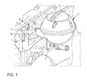
- FIG. 1 is a to be arranged on a designed as a sheet metal part holding structure 1 provided container 2 in a perspective view to recognize.
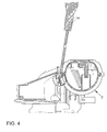
- the container 2 has a laterally projecting formation 4, which in the in the FIGS. 4 and 5 recognizable mounting position passes through the recess 3 and undercuts an upper edge region 5 of the recess 3.
- the container 2 is lowered or pushed with its shape 4 along a vertical joining axis in the joining direction 6 translationally until the in FIG. 2 shown, predetermined mounting position is reached.
- a guide pin 7 is arranged on the container 2.
- a guide pin 7 is arranged, which is inserted and held in a guide pin receptacle 18. Also, the guide pin 7 could be placed on the guide pin receptacle 18 and thus supportively receive holding forces.
- a integrally formed with the molding 4 locking projection 8 is used to define and thus the safety of the container 2 in this mounting position.
- a latching lug 9 of the latching projection 8 is deflected during assembly against an elastic restoring force, so that upon reaching the mounting position automatically in a further, in FIG. 1 shown recess 10 engages in the support structure 1 and undercuts an edge region 11 of the support structure 1, so as to block an undesired movement of the container 2 relative to the support structure 1 against the joining direction 6.
- the molding 4 and the locking projection 8 are in the mounting position against a back of the container 2 rear surface 12 of the support structure 1 in the same plane.
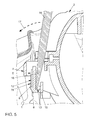
- For releasing the locking projection 8 by a renewed elastic deformation of the latching projection 8 has a pocket-shaped receptacle 13 for a merely schematically illustrated tool 14 for transmitting a leverage.
- the tool 14 in the receptacle 13 against a detent 9 facing away from abutment surface 15 of the receptacle 13 and at the same time against a vertically spaced support surface 16 and pivoted in the direction of arrow 17 the locking lug 9 is separated from the edge region 11 and the fixation of the container 2 is released.
- the container 2 can then be easily moved against the joining direction 6 and separated from the support structure 1.
- Fig. 6 to 8 show further perspective detail views of the container 2, in which the molding 4, the locking projection 8, the latching lug 9 and the guide pin 7 are shown. Further shown is an elastic region 19 which can be deformed with the tool 14, not shown here, in order to move the latching lug 9 backwards.
- the elastic region 19 can be made elastically supportive by the choice of material and / or a step structure 20. It is also possible to form a region 21 elastically by the choice of material, so that the locking lug 9 is moved with the tool 14, not shown here. Also, with the same material, an elasticity of the region 19 and / or the region 20 can be produced by the thickness of the material.
- the locking pin 7 is formed star-shaped. The star shape offers a high load capacity and a secure fit with low material costs.
Landscapes
- Engineering & Computer Science (AREA)
- General Engineering & Computer Science (AREA)
- Mechanical Engineering (AREA)
- Moulds For Moulding Plastics Or The Like (AREA)
- Details Of Rigid Or Semi-Rigid Containers (AREA)
Abstract
Description
- Die Erfindung betrifft eine Anordnung eines insbesondere als Ausgleichsbehälter für Kühlwasser dienenden Behälters an einer eine Ausnehmung aufweisenden Haltestruktur, wobei der Behälter in einer Montageposition mit zumindest einer Ausformung einen Randbereich der Ausnehmung durch eine translatorische Bewegung in Fügerichtung hinterschneidend positionierbar und mit zumindest einem Rastvorsprung in der Montageposition festgelegt ist. Weiterhin betrifft die Erfindung ein Verfahren zur Montage eines Behälters an einer Haltestruktur.
- Eine solche Anordnung und das hierzu bestimmte Verfahren zur Fixierung wird beispielsweise in der
DE 10 2007 020 928 A1 beschrieben, die eine Halterung betrifft, mit der ein Modul eines Kraftfahrzeugs, beispielsweise ein Kühlmittelausgleichsbehälter, an einer Karosserie oder an einer anderen Komponente des Fahrzeugs befestigt werden kann. Um die in allen drei Raumrichtungen gesicherte Befestigung des Moduls ohne Schrauben zu realisieren, hat die Halterung einen Befestigungsabschnitt, mit dem das Modul am Kraftfahrzeug befestigbar ist, und einen hiervon abgewinkelten Auflageabschnitt, um darauf das Modul zu platzieren. Der beispielsweise horizontal angeordnete Auflageabschnitt besitzt eine Aufnahme, in die ein Zapfen des Moduls in vertikaler Richtung einführbar ist, wobei der Zapfen in eingeführtem Zustand in der Aufnahme in einer vorgegebenen Richtung längsverschiebbar ist. Der Befestigungsabschnitt besitzt zum einen eine Aufnahme, in die eine Lasche des Moduls bei dessen Bewegung in die besagte vorgegebene Richtung einfahren kann, und zum anderen einen Ausleger, der zum Eingehen einer formschlüssigen Verbindung mit einem dem Modul zugeordneten Sicherungsblock ausgebildet ist. Dabei erfolgt die Montage des Kraftfahrzeugmoduls, indem in einem ersten Schritt dieses in z-Richtung abgesenkt und in einem zweiten Schritt in x-Richtung verschoben wird. In einem optionalen dritten Schritt wird die formschlüssige Verbindung des Auslegers mit dem Sicherungsblock mithilfe eines zusätzlichen Befestigungsmittels in Gestalt einer Klammer gesichert. - Die
DE 103 43 697 A1 beschreibt eine Haltevorrichtung, mit der ein kugelförmiger Ausgleichsbehälter an einer Karosserie eines Kraftfahrzeugs befestigt werden kann. Der Ausgleichsbehälter besitzt in seinem unteren Bereich einen Vorsprung, der in eine Öffnung der Haltevorrichtung eingreift. Seitlich besitzt die Haltevorrichtung mindestens einen Vorsprung, der in eine korrespondierende Öffnung des Ausgleichsbehälters eingreift. Ein Rastelement sichert den Ausgleichsbehälter in dessen oberem Bereich. - Als nachteilig erweist sich bei diesem Stand der Technik die umständliche Montage bzw. Demontage, die zusätzlich zu der Fügerichtung immer auch eine weitere, von der Fügerichtung abweichende zusätzliche Bewegung, beispielsweise eine Verschiebung quer hierzu oder eine Schwenkbewegung erfordert, um den Behälter in der Montageposition zu sichern.
- Vor diesem Hintergrund liegt der Erfindung daher die Aufgabe zugrunde, eine Anordnung und ein Verfahren zu schaffen, die eine wesentlich vereinfachte Montage bzw. Demontage gestatten.
- Die erstgenannte Aufgabe wird gelöst mit einer Anordnung gemäß den Merkmalen des Patentanspruchs 1. Die Unteransprüche betreffen besonders zweckmäßige Weiterbildungen der Erfindung.
- Erfindungsgemäß ist also eine Anordnung vorgesehen, bei der die Ausformung und der Rastvorsprung einteilig verbunden sind. Indem die Ausformung und der Rastvorsprung zu einem Formkörper einteilig bzw. einstückig verbunden sind, wird die Montage wesentlich erleichtert, weil hierzu lediglich die Positionierung des einheitlichen Formkörpers mit einer einzigen anschließenden Fügebewegung erforderlich ist. Im Gegensatz zum Stand der Technik entfällt die Positionierung der verschiedenen, die Rastverbindung bildenden Elemente in zueinander beabstandeten Positionen und der anschließenden komplexen Fügebewegung in mehreren Ebenen. Hierdurch werden zugleich Montagefehler vermieden und die Fertigungszeiten reduziert. Weiterhin wird eine einfache und schnelle visuelle Kontrolle der so erreichten Anordnung ermöglicht, sodass die Qualitätskontrolle vereinfacht wird.
- Dabei erweist sich eine Ausgestaltung der vorliegenden Erfindung als besonders zweckmäßig, bei welcher die Ausformung in der Ausnehmung mit einem einzigen Freiheitsgrad beweglich ist und dadurch die Fügerichtung auf eine einachsige, translatorische Bewegung, vorzugsweise in Richtung der vertikalen Z-Achse, beschränkt werden kann. Hierdurch wird der Fügeprozess wesentlich vereinfacht, weil ausgehend von einer für den Monteur klar erkennbaren Startposition, in welcher die Ausformung in die Ausnehmung hineinreicht, der Behälter lediglich senkrecht nach unten verschoben werden muss, bis eine der Montageposition entsprechende Endposition erreicht ist. Durch eine geeignete Gestaltung oder Markierung kann zudem die Kontrolle der Montageposition erleichtert werden. Selbstverständlich beschränkt sich die Erfindung nicht auf eine vertikale Fügerichtung. Vielmehr haben sich auch bereits abweichende einachsige Fügerichtungen als vorteilhaft erwiesen, wenn die Montageposition unterhalb der Startposition liegt.
- Hingegen ist es besonders praxisgerecht, wenn die Ausnehmung im Wesentlichen in einer vertikalen Ebene verläuft und die Ausformung einen oberen Randbereich der Ausnehmung umgreift, um so die Fügerichtung durch die Wirkrichtung der Schwerkraft in optimaler Weise zu unterstützen. Insbesondere bleibt der Behälter in der Praxis sogar dann in seiner Montageposition, wenn der Rastvorsprung außer Funktion, beispielsweise beschädigt ist. Die Betriebssicherheit kann dadurch weiter verbessert werden.
- Eine unerwünschte seitliche Verlagerung oder Auslenkung kann wirkungsvoll beispielsweise durch eine formschlüssige Aufnahme der Ausformung oder des Rastvorsprungs in der jeweiligen Ausnehmung vermieden werden. Vorzugsweise weist die Ausnehmung seitliche Randbereiche als Führung für die Ausformung zur Vermeidung einer Bewegung quer zur Fügerichtung auf. Indem also die Ausnehmung nicht lediglich durch ein Profil oder eine Blechstruktur mit einer horizontal verlaufenden Kante gebildet ist, sondern als eine Durchbrechung, beispielsweise eine Öffnung, mit horizontalen und vertikalen, also seitlichen Randbereichen ausgeführt ist, wird eine seitliche Verlagerung ausgeschlossen. Zusätzliche seitliche Begrenzungselemente oder Anschläge sind daher nicht erforderlich.
- Bei den aus dem Stand der Technik bekannten Anordnungen wird durch eine Abfolge verschiedener Fügerichtungen der Behälter gegenüber der Haltestruktur gegen eine unerwünschte Verlagerung gesichert. Die Demontage erfolgt in umgekehrter Reihenfolge, also entgegen der jeweiligen Fügerichtung. Demgegenüber blockiert gemäß einer besonders bevorzugten Ausführungsform der Rastvorsprung in der Montageposition eine Bewegung des Behälters relativ zu der Haltestruktur entgegen der Fügerichtung. Indem zur Demontage die Hinterschneidung des Rastvorsprungs aufgehoben werden muss, ist ein unbeabsichtigtes Lösen des Behälters nahezu ausgeschlossen. Zudem wird die sichere Positionierung des Behälters entgegen dem Stand der Technik nicht durch die Komplexität der Abfolge verschiedener Fügerichtungen erreicht, sondern es wird erfindungsgemäß eine Trennung der Fügebewegung einerseits und der Sicherung der Montageposition andererseits vorgenommen. Der Rastvorsprung könnte manuell oder automatisiert in einer Ausnehmung gesichert werden. Weiterhin könnte die Haltestruktur einen elastisch verformbaren Bereich, beispielsweise eine federnde Zunge aufweisen, welche den Rastvorsprung in der Ausnehmung sichert und eine der Fügerichtung entgegengesetzte Bewegung verhindert. Besonders sinnvoll ist hingegen eine Ausgestaltung der Erfindung, bei welcher der Rastvorsprung entgegen einer elastischen Rückstellkraft verformbar ist und bei Erreichen der Montageposition die Haltestruktur hinterschneidet. Indem der Rastvorsprung zu Beginn des Montageprozesses elastisch verformt, insbesondere ausgelenkt wird und bei Erreichen der Montageposition selbsttätig unter dem Einfluss der elastischen Rückstellkraft in die Haltestruktur eingreift und dadurch verrastet, wird die Fixierung der Montageposition ohne einen zusätzlichen Arbeitsschritt für den Monteur kontrollierbar erreicht.
- Die Ausnehmung in der Haltestruktur könnte bei einer einfachen Variante durch einen bloßen, vorspringenden Materialstreifen realisiert werden, welcher von der Ausformung von oben und von dem Rastvorsprung von unten umgriffen ist. Besonders sinnvoll ist hingegen eine Abwandlung der vorliegenden Erfindung, bei welcher der Rastvorsprung in einer zweiten Ausnehmung der Haltestruktur festlegbar ist. Hierdurch wird in besonders einfacher Weise eine unerwünschte Verlagerung oder Auslenkung des Behälters vermieden, indem jede Ausnehmung der Haltestruktur die Ausformung einerseits und den Rastvorsprung andererseits seitlich einschließt bzw. formschlüssig aufnimmt.
- Der Rastvorsprung dient im Wesentlichen der Blockierung der Fügebewegung und ist daher vorzugsweise in einer Querebene zu der Fügerichtung beweglich. Besonders sinnvoll ist hingegen auch eine Ausgestaltung der vorliegenden Erfindung, bei der die Ausformung und der Rastvorsprung in der Montageposition einander gegenüberliegend gegen eine dem Behälter abgewandte Rückseite der Haltestruktur in derselben Ebene anliegen. Indem die Ausformung und der Rastvorsprung von entgegengesetzten Seiten dieselbe Fläche hinterschneiden, wird nicht nur eine Zentrierung erreicht, sondern die aufgrund der Hinterschneidung wirkenden Kräfte heben sich gegenseitig auf. Zudem wird der Behälter dadurch in der gewünschten Montageposition nahezu spielfrei gehalten, wenn die jeweiligen, die Haltestruktur hinterschneidenden Bereiche der Ausformung und des Rastvorsprungs einander zugewandt sind.
- Der Behälter ist durch die Ausformung einerseits und den Rastvorsprung andererseits bereits zuverlässig und unbeweglich fixiert. Darüber hinaus hat es sich jedoch bereits als besonders praxisgerecht erwiesen, wenn der Behälter mit zumindest einem zu der Ausformung horizontal und/oder vertikal beabstandeten Führungszapfen ausgestattet ist, der in der Montageposition in eine Aufnahme eingreift und somit der Stabilisierung und der zusätzlichen Lastaufnahme dient. Je nach Gestaltung kann der Führungszapfen einen Großteil der auf den Behälter wirkenden Gewichtskräfte und dynamischen Kräfte aufnehmen, um so die Ausformung vor einer Überlastung zu schützen. Vorzugsweise ist der Führungszapfen mit seiner Haupterstreckung parallel zu der Fügerichtung angeordnet.
- Der Rastvorsprung könnte beispielsweise mittels Verschieben eines Schiebers, welcher entlang der dem Behälter abgewandten Rückseite der Haltestruktur gegen den hinterschneidenden Bereich des Rastvorsprungs anliegt, aus der hinterschneidenden Position gelöst werden. In dieser Position kann der Behälter entgegen der Fügerichtung bewegt werden. Besonders einfach ist hingegen eine Ausgestaltung der Erfindung, bei welcher der Rastvorsprung eine der Haltestruktur abgewandte, insbesondere als eine Tasche ausgeführte Aufnahme für ein Werkzeug hat. Hierdurch ist eine Zugänglichkeit zu der Rückseite der Haltestruktur entbehrlich, sodass aufgrund der guten Zugänglichkeit der Vorderseite der Haltestruktur die Demontage des Behälters wesentlich erleichtert wird. Indem das als Hebelwerkzeug ausgeführte Werkzeug in die Aufnahme eingesetzt wird und um eine von der Aufnahme abweichende Stützfläche verschwenkt wird, wird der Rastvorsprung in der gewünschten Weise elastisch verformt und die Hinterschneidung dadurch aufgehoben. Die Aufnahme ist dabei dem Rastvorsprung beispielsweise angeformt und durch eine Öffnung realisiert, in die das Werkzeug einsetzbar ist.
- Vorzugsweise hat die Aufnahme eine dem Rastvorsprung gegenüberliegende Anlagefläche und eine zu dieser vertikal beabstandete Stützfläche für ein Hebelwerkzeug, welches zwischen der Haltestruktur und dem Behälter einführbar ist. Bei dem Hebelwerkzeug kann es sich beispielsweise um einen handelsüblichen Schraubendreher handeln.
- Die zweitgenannte Aufgabe, ein Verfahren zur Montage eines Behälters an einer Haltestruktur zu schaffen, bei dem der Behälter in Fügerichtung in eine Montageposition bewegt wird, in welcher zumindest eine Ausformung eine Ausnehmung der Haltestruktur hinterschneidet und durch einen Rastvorsprung gesichert ist, wird erfindungsgemäß dadurch gelöst, dass die Ausformung relativ zu der Ausnehmung entlang einer einachsigen Fügerichtung bewegt wird, bis der Rastvorsprung einen Randbereich der Haltestruktur hinterschneidet und dadurch eine Bewegung entgegen der Fügerichtung blockiert. Hierdurch wird der Fügevorgang wesentlich erleichtert, weil nicht etwa mehrere Bewegungen nacheinander ausgeführt werden müssen, um den Behälter in der Montageposition zu sichern. Vielmehr beschränkt sich der Fügevorgang auf eine translatorische Bewegung entlang einer einzigen Achse, die durch eine selbsttätige Verrastung des Rastvorsprungs in der Haltestruktur abgeschlossen wird.
- Dabei erweist es sich als besonders zweckmäßig, wenn der Rastvorsprung aufgrund der Fügebewegung der Ausformung entgegen einer elastischen Rückstellkraft verformt wird und bei Erreichen der Montageposition in die Startposition zurückkehrt und die Haltestruktur hinterschneidet. Hierdurch entfällt ein zusätzlicher Verfahrensschritt zur Realisierung der Hinterschneidung des Rastvorsprungs, indem dieser zunächst durch das Einführen der Ausformung in die Ausnehmung elastisch verformt wird und schließlich selbsttätig in der Montageposition in die korrespondierende Durchbrechung eingreift.
- Zum Lösen der Verbindung erweist es sich als besonders praxisgerecht, wenn der Rastvorsprung mittels eines Werkzeugs elastisch verformt wird, indem dieses mit einer der Haltestruktur abgewandten Aufnahme des Rastvorsprungs verbunden und das Werkzeug um eine Stützfläche herum verschwenkt wird, sodass die elastische Verformung durch das Werkzeug von einer Vorderseite aus durchgeführt werden kann.
- Die Erfindung lässt zahlreiche Ausführungsformen zu. Zur weiteren Verdeutlichung ihres Grundprinzips ist eine davon in der Zeichnung dargestellt und wird nachfolgend beschrieben. Diese zeigt in
- Fig. 1
- eine perspektivische Ansicht einer Haltestruktur und eines daran anzuordnenden Behälters;
- Fig. 2
- eine perspektivische Ansicht des an der Haltestruktur fixierten Behälters;
- Fig. 3
- eine Draufsicht auf die Haltestruktur und den daran fixierten Behälter;
- Fig. 4
- eine geschnittene Seitenansicht des an der Haltestruktur fixierten Behälters;
- Fig. 5
- eine vergrößerte Detaildarstellung gemäß
Figur 4 und - Fig. 6 - 8
- weitere perspektivische Detailansichten des Behälters.
- In
Figur 1 ist ein zur Anordnung an einer als Blechformteil ausgeführten Haltestruktur 1 vorgesehener Behälter 2 in einer perspektivischen Darstellung zu erkennen. Zur Fixierung des Behälters 2 in einer Ausnehmung 3 der Haltestruktur 1 hat der Behälter 2 eine seitlich vorspringende Ausformung 4, die in der in denFiguren 4 und5 erkennbaren Montageposition durch die Ausnehmung 3 hindurchgreift und einen oberen Randbereich 5 der Ausnehmung 3 hinterschneidet. Hierzu wird der Behälter 2 mit seiner Ausformung 4 entlang einer vertikalen Fügeachse in Fügerichtung 6 translatorisch abgesenkt bzw. eingeschoben, bis die inFigur 2 gezeigte, vorbestimmte Montageposition erreicht ist. Obwohl der Behälter 2 auch bereits durch eine einzige, in die Ausnehmung 3 eingreifende Ausformung 4 zuverlässig fixiert ist, verbessern zwei zueinander beabstandete Ausformungen 4, die nach demselben Funktionsprinzip fixierbar sind, jedoch hingegen keine übereinstimmenden Abmessungen aufweisen müssen, die übertragbaren Haltekräfte, wie dies insbesondere ausFigur 3 ersichtlich ist. Ferner ist am Behälter 2 ein Führungszapfen 7 angeordnet. - In der Montageposition werden, wie in den
Figuren 4 und5 näher dargestellt, die Haltekräfte im Wesentlichen durch die beiden Ausformungen 4 in ihrer jeweiligen Ausnehmung 3 in der Haltestruktur 1, die zugleich eine seitliche Führung für die jeweilige Ausformung 4 bildet, zur Vermeidung einer Bewegung quer zur Fügerichtung und ergänzend um Haltekräfte aufzunehmen ist, inFigur 2 ein Führungszapfen 7 angeordnet, der in eine Führungszapfenaufnahme 18 eingesteckt und gehalten wird. Auch könnte der Führungszapfen 7 auf die Führungszapfenaufnahme 18 aufgelegt werden und somit abstützend Haltekräfte aufnehmen. Ein mit der Ausformung 4 einteilig verbundener Rastvorsprung 8 dient der Festlegung und damit der Sicherung des Behälters 2 in dieser Montageposition. Hierzu wird eine Rastnase 9 des Rastvorsprungs 8 bei der Montage entgegen einer elastischen Rückstellkraft ausgelenkt, sodass diese bei Erreichen der Montageposition selbsttätig in eine weitere, inFigur 1 dargestellte Ausnehmung 10 in der Haltestruktur 1 eingreift und einen Randbereich 11 der Haltestruktur 1 hinterschneidet, um so eine unerwünschte Bewegung des Behälters 2 relativ zu der Haltestruktur 1 entgegen der Fügerichtung 6 zu blockieren. - Die Ausformung 4 und der Rastvorsprung 8 liegen in der Montageposition gegen eine dem Behälter 2 abgewandte rückseitige Fläche 12 der Haltestruktur 1 in derselben Ebene an. Zum Lösen des Rastvorsprungs 8 durch eine erneute elastische Verformung hat der Rastvorsprung 8 eine taschenförmige Aufnahme 13 für ein lediglich andeutungsweise dargestelltes Werkzeug 14 zur Übertragung einer Hebelkraft. Indem das Werkzeug 14 in der Aufnahme 13 gegen eine der Rastnase 9 abgewandte Anlagefläche 15 der Aufnahme 13 und zugleich gegen eine zu dieser vertikal beabstandeten Stützfläche 16 angelegt und in Pfeilrichtung 17 verschwenkt wird, wird die Rastnase 9 von dem Randbereich 11 getrennt und die Fixierung des Behälters 2 aufgehoben. Der Behälter 2 kann dann problemlos entgegen der Fügerichtung 6 bewegt und von der Haltestruktur 1 getrennt werden.
-
Fig. 6 bis 8 zeigen weitere perspektivische Detailansichten des Behälters 2, in der die Ausformung 4, der Rastvorsprung 8, die Rastnase 9 und der Führungszapfen 7 dargestellt sind. Ferner ist aufgezeigt ein elastische Bereich 19 der mit dem Werkzeug 14, hier nicht dargestellt, verformt werden kann um die Rastnase 9 nach hinten zu bewegen. Der elastische Bereich 19 kann durch die Materialwahl und/oder einer Stufenstruktur 20 unterstützend elastisch ausgebildet werden. Auch ist es möglich einen Bereich 21 durch die Materialwahl elastisch auszubilden, damit mit dem Werkzeug 14, hier nicht dargestellt, die Rastnase 9 bewegt wird. Auch kann bei gleichem Material durch die Dicke des Materials, eine Elastizität des Bereiches 19 und/oder des Bereichs 20 hergestellt werden. Der Rastzapfen 7 ist sternförmig ausgebildet. Die Sternform bietet bei geringem Materialaufwand einen hohe Tragfähigkeit und sicheren Halt. -
- 1
- Haltestruktur
- 2
- Behälter
- 3
- Ausnehmung
- 4
- Ausformung
- 5
- Randbereich
- 6
- Fügerichtung
- 7
- Führungszapfen
- 8
- Rastvorsprung
- 9
- Rastnase
- 10
- Ausnehmung
- 11
- Randbereich
- 12
- Fläche
- 13
- Aufnahme
- 14
- Werkzeug
- 15
- Anlagefläche
- 16
- Stützfläche
- 17
- Pfeilrichtung
- 18
- Führungszapfenaufnahme
- 19
- elastische Bereich
- 20
- Stufenstruktur
- 21
- elastische Bereich
Claims (10)
- Anordnung eines insbesondere als Ausgleichsbehälter für Kühlwasser dienenden Behälters (2) an einer eine Ausnehmung (3, 10) aufweisenden Haltestruktur (1), wobei der Behälter (2) in einer Montageposition mit zumindest einer Ausformung (4) einen Randbereich (5) der Ausnehmung (3) durch eine translatorische Bewegung in Fügerichtung (6) hinterschneidend positioniert ist und mit zumindest einem Rastvorsprung (8) festgelegt ist, dadurch gekennzeichnet, dass die Ausformung (4) und der Rastvorsprung (8) einteilig verbunden sind.
- Anordnung nach Anspruch 1, dadurch gekennzeichnet, dass die Ausformung (4) in der Ausnehmung (3) mit einem einzigen Freiheitsgrad beweglich ist.
- Anordnung nach den Ansprüchen 1 oder 2, dadurch gekennzeichnet, dass die Ausnehmung (3) im Wesentlichen in einer vertikalen Ebene verläuft und dass die Ausformung (4) einen oberen Randbereich (5) der Ausnehmung (3) umgreift.
- Anordnung nach zumindest einem der vorangehenden Ansprüche, dadurch gekennzeichnet, dass der Rastvorsprung (8) in der Montageposition eine Bewegung des Behälters (2) relativ zu der Haltestruktur (1) entgegen der Fügerichtung (6) blockiert.
- Anordnung nach zumindest einem der vorangehenden Ansprüche, dadurch gekennzeichnet, dass der Rastvorsprung (8) entgegen einer elastischen Rückstellkraft verformbar ist und bei Erreichen der Montageposition die Haltestruktur (1) hinterschneidet.
- Anordnung nach zumindest einem der vorangehenden Ansprüche, dadurch gekennzeichnet, dass die Ausformung (4) und der Rastvorsprung (8) in der Montageposition einander gegenüberliegend gegen eine dem Behälter (2) abgewandte Fläche (12) der Haltestruktur (1) in derselben Ebene anliegen.
- Anordnung nach zumindest einem der vorangehenden Ansprüche, dadurch gekennzeichnet, dass die jeweiligen, die Haltestruktur (1) hinterschneidenden Bereiche der Ausformung (4) und des Rastvorsprungs (8) einander zugewandt sind.
- Anordnung nach zumindest einem der vorangehenden Ansprüche, dadurch gekennzeichnet, dass der Rastvorsprung (8) eine der Haltestruktur (1) abgewandte, insbesondere als eine Tasche ausgeführte Aufnahme (13) für ein Werkzeug (14) hat.
- Verfahren zur Montage eines Behälters (2) an einer Haltestruktur (1), bei dem der Behälter (2) in eine Montageposition bewegt wird, in welcher zumindest eine Ausformung (4) eine Ausnehmung (3) der Haltestruktur (1) hinterschneidet und durch einen Rastvorsprung (8) gesichert ist, dadurch gekennzeichnet, dass die Ausformung (4) relativ zu der Ausnehmung (3) entlang einer einachsigen Fügerichtung (6) bewegt wird, bis der Rastvorsprung (8) einen Randbereich (5) der Haltestruktur (1) hinterschneidet und dadurch eine Bewegung entgegen der Fügerichtung (6) blockiert.
- Verfahren nach Anspruch 9, dadurch gekennzeichnet, dass der Rastvorsprung (8) aufgrund der Fügebewegung der Ausformung (4) entgegen einer elastischen Rückstellkraft verformt wird und bei Erreichen der Montageposition die Haltestruktur (1) hinterschneidet.
Applications Claiming Priority (1)
| Application Number | Priority Date | Filing Date | Title |
|---|---|---|---|
| DE102012020397.7A DE102012020397A1 (de) | 2012-10-18 | 2012-10-18 | Anordnung eines Behälters an einer Haltestruktur sowie Verfahren zu deren Montage |
Publications (2)
| Publication Number | Publication Date |
|---|---|
| EP2722532A1 true EP2722532A1 (de) | 2014-04-23 |
| EP2722532B1 EP2722532B1 (de) | 2017-05-31 |
Family
ID=48917424
Family Applications (1)
| Application Number | Title | Priority Date | Filing Date |
|---|---|---|---|
| EP13179284.8A Active EP2722532B1 (de) | 2012-10-18 | 2013-08-05 | Anordnung eines Behälters an einer Haltestruktur sowie Verfahren zu deren Montage |
Country Status (3)
| Country | Link |
|---|---|
| EP (1) | EP2722532B1 (de) |
| CN (1) | CN203920400U (de) |
| DE (1) | DE102012020397A1 (de) |
Families Citing this family (2)
| Publication number | Priority date | Publication date | Assignee | Title |
|---|---|---|---|---|
| DE102018220292A1 (de) * | 2018-11-26 | 2020-05-28 | Volkswagen Aktiengesellschaft | Anordnung eines separaten Funktionselements eines Waschwasserbehälters an einem Fixierabschnitt eines Strukturbauteils |
| DE102021205249B4 (de) | 2021-05-21 | 2024-05-02 | Volkswagen Aktiengesellschaft | Befestigungseinrichtung für einen Behälter eines Kraftfahrzeugs |
Citations (6)
| Publication number | Priority date | Publication date | Assignee | Title |
|---|---|---|---|---|
| DD215285A1 (de) * | 1983-06-03 | 1984-11-07 | Sachsenring Automobilwerke | Kraftfahrzeug |
| GB2160579A (en) * | 1984-06-19 | 1985-12-24 | Raymond A | Spring clip which can be fixed in a hole in a plate or panel |
| DE19953786A1 (de) * | 1999-11-09 | 2001-05-10 | Behr Gmbh & Co | Kühlmittelkühler mit einem Ausgleichsbehälter |
| WO2004090352A1 (es) * | 2003-04-10 | 2004-10-21 | Grupo Antolín-Ingenería, S.A. | Dispositivo de montaje de carcasas en soportes |
| DE10343697A1 (de) | 2003-09-18 | 2005-06-09 | Behr Gmbh & Co. Kg | Montageanordnung für Ausgleichsbehälter |
| DE102007020928A1 (de) | 2007-05-04 | 2008-11-06 | GM Global Technology Operations, Inc., Detroit | Halterung für die Befestigung eines Kfz-Moduls |
Family Cites Families (4)
| Publication number | Priority date | Publication date | Assignee | Title |
|---|---|---|---|---|
| JPH07217604A (ja) * | 1994-01-31 | 1995-08-15 | Unisia Jecs Corp | リザーブタンクの取付構造 |
| DE19637995C1 (de) * | 1996-09-18 | 1998-01-15 | Daimler Benz Ag | Vorrichtung zur lösbaren Befestigung eines Behälters |
| FR2921019B1 (fr) * | 2007-09-13 | 2010-01-08 | Renault Sas | Agencement de fixation d'un reservoir de liquide sur un element de structure d'un vehicule automobile |
| DE102010023488B4 (de) * | 2009-09-29 | 2014-04-30 | Bayerische Motoren Werke Aktiengesellschaft | System zum Befestigen eines Behälters an einer Fahrzeugkarosserie |
-
2012
- 2012-10-18 DE DE102012020397.7A patent/DE102012020397A1/de not_active Withdrawn
-
2013
- 2013-08-05 EP EP13179284.8A patent/EP2722532B1/de active Active
- 2013-10-18 CN CN201320646113.XU patent/CN203920400U/zh not_active Expired - Lifetime
Patent Citations (6)
| Publication number | Priority date | Publication date | Assignee | Title |
|---|---|---|---|---|
| DD215285A1 (de) * | 1983-06-03 | 1984-11-07 | Sachsenring Automobilwerke | Kraftfahrzeug |
| GB2160579A (en) * | 1984-06-19 | 1985-12-24 | Raymond A | Spring clip which can be fixed in a hole in a plate or panel |
| DE19953786A1 (de) * | 1999-11-09 | 2001-05-10 | Behr Gmbh & Co | Kühlmittelkühler mit einem Ausgleichsbehälter |
| WO2004090352A1 (es) * | 2003-04-10 | 2004-10-21 | Grupo Antolín-Ingenería, S.A. | Dispositivo de montaje de carcasas en soportes |
| DE10343697A1 (de) | 2003-09-18 | 2005-06-09 | Behr Gmbh & Co. Kg | Montageanordnung für Ausgleichsbehälter |
| DE102007020928A1 (de) | 2007-05-04 | 2008-11-06 | GM Global Technology Operations, Inc., Detroit | Halterung für die Befestigung eines Kfz-Moduls |
Also Published As
| Publication number | Publication date |
|---|---|
| EP2722532B1 (de) | 2017-05-31 |
| DE102012020397A1 (de) | 2014-04-24 |
| CN203920400U (zh) | 2014-11-05 |
Similar Documents
| Publication | Publication Date | Title |
|---|---|---|
| DE102006042337B3 (de) | Halteelement zur Befestigung eines Ausstattungselements an einer Tragschiene | |
| DE102015106223B4 (de) | System zur Befestigung eines Türmoduls an einer Automobiltür | |
| DE102009045722B4 (de) | Bauteilträger | |
| EP2344776A1 (de) | Befestigungsclip | |
| WO2012038253A1 (de) | Befestigungssystem | |
| DE102009028533B4 (de) | Befestigungssystem in einem Luft- und Raumfahrzeug | |
| DE102016109499A1 (de) | System aus einem Bauteil und einer Befestigungsvorrichtung | |
| EP2722532B1 (de) | Anordnung eines Behälters an einer Haltestruktur sowie Verfahren zu deren Montage | |
| WO2011138091A1 (de) | Wischermotor mit entkopplungselement und entkopplungselement | |
| DE19923487B4 (de) | Widerlager mit Formteil zum Befestigen von Betätigungszügen | |
| DE102011089015A1 (de) | Verbindungsanordnung für Karosseriebauteile eines Fahrzeugs | |
| DE202010008626U1 (de) | Clipselement | |
| DE102015226051B4 (de) | Anordnung eines Scheinwerfers gegenüber einem rohbauseitig festgelegten Trägerelement sowie Verfahren zur Feinjustierung eines lösbar befestigten Scheinwerfers gegenüber einem rohbauseitig festgelegten Trägerelement eines Kraftfahrzeugs | |
| DE102018115527A1 (de) | Verbindungsvorrichtung zur lösbaren Befestigung eines Anbauteils an einem Fahrrad | |
| WO2010060633A1 (de) | U-förmiger befestigungsclip | |
| DE102008044027B4 (de) | Mechanisches Befestigungssystem sowie Verfahren zur Befestigung eines Bauteiles an einem Festkörper | |
| DE102019203567B4 (de) | Verstellvorrichtung für einen Fahrzeugsitz mit mehrteiligem Motorträger zwischen zwei Schienenanordnungen und Fahrzeugsitz mit einer Verstellvorrichtung | |
| DE102010062902A1 (de) | Wischblattvorrichtung | |
| DE102011009734A1 (de) | Rasthalteelement für die reversible Befestigung von Bauteilen, insb. für die Wand- oder Deckenmontage von Bildwandsystemen | |
| WO2022017978A1 (de) | Befestigungsanordnung, kraftfahrzeug | |
| EP1820729B1 (de) | Flugzeugsitzbefestigungsvorrichtung | |
| DE102020123288B4 (de) | Befestigungselement zum Befestigen eines Anbauteils im Innenraum eines Kraftfahrzeuges | |
| DE102019118816A1 (de) | Kontaktträger zum Bereitstellen einer Kontaktierung für eine Verkabelung in einem Fahrzeug | |
| DE102009033129A1 (de) | Vorrichtung zur Anbringung eines Verkleidungsteils an einem Karosserieteil eines Kraftfahrzeugs | |
| DE102009009883A1 (de) | Verbindungsanordnung zum Verbinden eines Anbauteils mit einem Trägerteil |
Legal Events
| Date | Code | Title | Description |
|---|---|---|---|
| PUAI | Public reference made under article 153(3) epc to a published international application that has entered the european phase |
Free format text: ORIGINAL CODE: 0009012 |
|
| AK | Designated contracting states |
Kind code of ref document: A1 Designated state(s): AL AT BE BG CH CY CZ DE DK EE ES FI FR GB GR HR HU IE IS IT LI LT LU LV MC MK MT NL NO PL PT RO RS SE SI SK SM TR |
|
| AX | Request for extension of the european patent |
Extension state: BA ME |
|
| 17P | Request for examination filed |
Effective date: 20141023 |
|
| RBV | Designated contracting states (corrected) |
Designated state(s): AL AT BE BG CH CY CZ DE DK EE ES FI FR GB GR HR HU IE IS IT LI LT LU LV MC MK MT NL NO PL PT RO RS SE SI SK SM TR |
|
| 17Q | First examination report despatched |
Effective date: 20160302 |
|
| GRAP | Despatch of communication of intention to grant a patent |
Free format text: ORIGINAL CODE: EPIDOSNIGR1 |
|
| RIC1 | Information provided on ipc code assigned before grant |
Ipc: B60K 11/02 20060101ALN20170119BHEP Ipc: F01P 11/02 20060101ALN20170119BHEP Ipc: F16B 5/06 20060101AFI20170119BHEP |
|
| INTG | Intention to grant announced |
Effective date: 20170217 |
|
| GRAS | Grant fee paid |
Free format text: ORIGINAL CODE: EPIDOSNIGR3 |
|
| GRAA | (expected) grant |
Free format text: ORIGINAL CODE: 0009210 |
|
| AK | Designated contracting states |
Kind code of ref document: B1 Designated state(s): AL AT BE BG CH CY CZ DE DK EE ES FI FR GB GR HR HU IE IS IT LI LT LU LV MC MK MT NL NO PL PT RO RS SE SI SK SM TR |
|
| REG | Reference to a national code |
Ref country code: CH Ref legal event code: EP Ref country code: GB Ref legal event code: FG4D Free format text: NOT ENGLISH |
|
| REG | Reference to a national code |
Ref country code: AT Ref legal event code: REF Ref document number: 897757 Country of ref document: AT Kind code of ref document: T Effective date: 20170615 |
|
| REG | Reference to a national code |
Ref country code: IE Ref legal event code: FG4D Free format text: LANGUAGE OF EP DOCUMENT: GERMAN |
|
| REG | Reference to a national code |
Ref country code: DE Ref legal event code: R096 Ref document number: 502013007356 Country of ref document: DE |
|
| REG | Reference to a national code |
Ref country code: FR Ref legal event code: PLFP Year of fee payment: 5 |
|
| REG | Reference to a national code |
Ref country code: NL Ref legal event code: MP Effective date: 20170531 |
|
| REG | Reference to a national code |
Ref country code: LT Ref legal event code: MG4D |
|
| PG25 | Lapsed in a contracting state [announced via postgrant information from national office to epo] |
Ref country code: HR Free format text: LAPSE BECAUSE OF FAILURE TO SUBMIT A TRANSLATION OF THE DESCRIPTION OR TO PAY THE FEE WITHIN THE PRESCRIBED TIME-LIMIT Effective date: 20170531 Ref country code: ES Free format text: LAPSE BECAUSE OF FAILURE TO SUBMIT A TRANSLATION OF THE DESCRIPTION OR TO PAY THE FEE WITHIN THE PRESCRIBED TIME-LIMIT Effective date: 20170531 Ref country code: NO Free format text: LAPSE BECAUSE OF FAILURE TO SUBMIT A TRANSLATION OF THE DESCRIPTION OR TO PAY THE FEE WITHIN THE PRESCRIBED TIME-LIMIT Effective date: 20170831 Ref country code: FI Free format text: LAPSE BECAUSE OF FAILURE TO SUBMIT A TRANSLATION OF THE DESCRIPTION OR TO PAY THE FEE WITHIN THE PRESCRIBED TIME-LIMIT Effective date: 20170531 Ref country code: LT Free format text: LAPSE BECAUSE OF FAILURE TO SUBMIT A TRANSLATION OF THE DESCRIPTION OR TO PAY THE FEE WITHIN THE PRESCRIBED TIME-LIMIT Effective date: 20170531 Ref country code: GR Free format text: LAPSE BECAUSE OF FAILURE TO SUBMIT A TRANSLATION OF THE DESCRIPTION OR TO PAY THE FEE WITHIN THE PRESCRIBED TIME-LIMIT Effective date: 20170901 |
|
| PG25 | Lapsed in a contracting state [announced via postgrant information from national office to epo] |
Ref country code: LV Free format text: LAPSE BECAUSE OF FAILURE TO SUBMIT A TRANSLATION OF THE DESCRIPTION OR TO PAY THE FEE WITHIN THE PRESCRIBED TIME-LIMIT Effective date: 20170531 Ref country code: BG Free format text: LAPSE BECAUSE OF FAILURE TO SUBMIT A TRANSLATION OF THE DESCRIPTION OR TO PAY THE FEE WITHIN THE PRESCRIBED TIME-LIMIT Effective date: 20170831 Ref country code: NL Free format text: LAPSE BECAUSE OF FAILURE TO SUBMIT A TRANSLATION OF THE DESCRIPTION OR TO PAY THE FEE WITHIN THE PRESCRIBED TIME-LIMIT Effective date: 20170531 Ref country code: SE Free format text: LAPSE BECAUSE OF FAILURE TO SUBMIT A TRANSLATION OF THE DESCRIPTION OR TO PAY THE FEE WITHIN THE PRESCRIBED TIME-LIMIT Effective date: 20170531 Ref country code: RS Free format text: LAPSE BECAUSE OF FAILURE TO SUBMIT A TRANSLATION OF THE DESCRIPTION OR TO PAY THE FEE WITHIN THE PRESCRIBED TIME-LIMIT Effective date: 20170531 Ref country code: IS Free format text: LAPSE BECAUSE OF FAILURE TO SUBMIT A TRANSLATION OF THE DESCRIPTION OR TO PAY THE FEE WITHIN THE PRESCRIBED TIME-LIMIT Effective date: 20170930 |
|
| PG25 | Lapsed in a contracting state [announced via postgrant information from national office to epo] |
Ref country code: DK Free format text: LAPSE BECAUSE OF FAILURE TO SUBMIT A TRANSLATION OF THE DESCRIPTION OR TO PAY THE FEE WITHIN THE PRESCRIBED TIME-LIMIT Effective date: 20170531 Ref country code: EE Free format text: LAPSE BECAUSE OF FAILURE TO SUBMIT A TRANSLATION OF THE DESCRIPTION OR TO PAY THE FEE WITHIN THE PRESCRIBED TIME-LIMIT Effective date: 20170531 Ref country code: CZ Free format text: LAPSE BECAUSE OF FAILURE TO SUBMIT A TRANSLATION OF THE DESCRIPTION OR TO PAY THE FEE WITHIN THE PRESCRIBED TIME-LIMIT Effective date: 20170531 Ref country code: RO Free format text: LAPSE BECAUSE OF FAILURE TO SUBMIT A TRANSLATION OF THE DESCRIPTION OR TO PAY THE FEE WITHIN THE PRESCRIBED TIME-LIMIT Effective date: 20170531 Ref country code: SK Free format text: LAPSE BECAUSE OF FAILURE TO SUBMIT A TRANSLATION OF THE DESCRIPTION OR TO PAY THE FEE WITHIN THE PRESCRIBED TIME-LIMIT Effective date: 20170531 |
|
| PG25 | Lapsed in a contracting state [announced via postgrant information from national office to epo] |
Ref country code: IT Free format text: LAPSE BECAUSE OF FAILURE TO SUBMIT A TRANSLATION OF THE DESCRIPTION OR TO PAY THE FEE WITHIN THE PRESCRIBED TIME-LIMIT Effective date: 20170531 Ref country code: SM Free format text: LAPSE BECAUSE OF FAILURE TO SUBMIT A TRANSLATION OF THE DESCRIPTION OR TO PAY THE FEE WITHIN THE PRESCRIBED TIME-LIMIT Effective date: 20170531 Ref country code: PL Free format text: LAPSE BECAUSE OF FAILURE TO SUBMIT A TRANSLATION OF THE DESCRIPTION OR TO PAY THE FEE WITHIN THE PRESCRIBED TIME-LIMIT Effective date: 20170531 |
|
| REG | Reference to a national code |
Ref country code: DE Ref legal event code: R097 Ref document number: 502013007356 Country of ref document: DE |
|
| REG | Reference to a national code |
Ref country code: CH Ref legal event code: PL |
|
| PG25 | Lapsed in a contracting state [announced via postgrant information from national office to epo] |
Ref country code: MC Free format text: LAPSE BECAUSE OF FAILURE TO SUBMIT A TRANSLATION OF THE DESCRIPTION OR TO PAY THE FEE WITHIN THE PRESCRIBED TIME-LIMIT Effective date: 20170531 |
|
| PLBE | No opposition filed within time limit |
Free format text: ORIGINAL CODE: 0009261 |
|
| STAA | Information on the status of an ep patent application or granted ep patent |
Free format text: STATUS: NO OPPOSITION FILED WITHIN TIME LIMIT |
|
| PG25 | Lapsed in a contracting state [announced via postgrant information from national office to epo] |
Ref country code: CH Free format text: LAPSE BECAUSE OF NON-PAYMENT OF DUE FEES Effective date: 20170831 Ref country code: LI Free format text: LAPSE BECAUSE OF NON-PAYMENT OF DUE FEES Effective date: 20170831 |
|
| 26N | No opposition filed |
Effective date: 20180301 |
|
| REG | Reference to a national code |
Ref country code: IE Ref legal event code: MM4A |
|
| PG25 | Lapsed in a contracting state [announced via postgrant information from national office to epo] |
Ref country code: SI Free format text: LAPSE BECAUSE OF FAILURE TO SUBMIT A TRANSLATION OF THE DESCRIPTION OR TO PAY THE FEE WITHIN THE PRESCRIBED TIME-LIMIT Effective date: 20170531 |
|
| REG | Reference to a national code |
Ref country code: BE Ref legal event code: MM Effective date: 20170831 |
|
| PG25 | Lapsed in a contracting state [announced via postgrant information from national office to epo] |
Ref country code: LU Free format text: LAPSE BECAUSE OF NON-PAYMENT OF DUE FEES Effective date: 20170805 |
|
| PG25 | Lapsed in a contracting state [announced via postgrant information from national office to epo] |
Ref country code: IE Free format text: LAPSE BECAUSE OF NON-PAYMENT OF DUE FEES Effective date: 20170805 |
|
| REG | Reference to a national code |
Ref country code: FR Ref legal event code: PLFP Year of fee payment: 6 |
|
| PG25 | Lapsed in a contracting state [announced via postgrant information from national office to epo] |
Ref country code: BE Free format text: LAPSE BECAUSE OF NON-PAYMENT OF DUE FEES Effective date: 20170831 |
|
| PG25 | Lapsed in a contracting state [announced via postgrant information from national office to epo] |
Ref country code: MT Free format text: LAPSE BECAUSE OF FAILURE TO SUBMIT A TRANSLATION OF THE DESCRIPTION OR TO PAY THE FEE WITHIN THE PRESCRIBED TIME-LIMIT Effective date: 20170531 |
|
| PG25 | Lapsed in a contracting state [announced via postgrant information from national office to epo] |
Ref country code: HU Free format text: LAPSE BECAUSE OF FAILURE TO SUBMIT A TRANSLATION OF THE DESCRIPTION OR TO PAY THE FEE WITHIN THE PRESCRIBED TIME-LIMIT; INVALID AB INITIO Effective date: 20130805 |
|
| REG | Reference to a national code |
Ref country code: AT Ref legal event code: MM01 Ref document number: 897757 Country of ref document: AT Kind code of ref document: T Effective date: 20180805 |
|
| PG25 | Lapsed in a contracting state [announced via postgrant information from national office to epo] |
Ref country code: CY Free format text: LAPSE BECAUSE OF NON-PAYMENT OF DUE FEES Effective date: 20170531 |
|
| PG25 | Lapsed in a contracting state [announced via postgrant information from national office to epo] |
Ref country code: MK Free format text: LAPSE BECAUSE OF FAILURE TO SUBMIT A TRANSLATION OF THE DESCRIPTION OR TO PAY THE FEE WITHIN THE PRESCRIBED TIME-LIMIT Effective date: 20170531 |
|
| PG25 | Lapsed in a contracting state [announced via postgrant information from national office to epo] |
Ref country code: AT Free format text: LAPSE BECAUSE OF NON-PAYMENT OF DUE FEES Effective date: 20180805 |
|
| PG25 | Lapsed in a contracting state [announced via postgrant information from national office to epo] |
Ref country code: TR Free format text: LAPSE BECAUSE OF FAILURE TO SUBMIT A TRANSLATION OF THE DESCRIPTION OR TO PAY THE FEE WITHIN THE PRESCRIBED TIME-LIMIT Effective date: 20170531 |
|
| PG25 | Lapsed in a contracting state [announced via postgrant information from national office to epo] |
Ref country code: PT Free format text: LAPSE BECAUSE OF FAILURE TO SUBMIT A TRANSLATION OF THE DESCRIPTION OR TO PAY THE FEE WITHIN THE PRESCRIBED TIME-LIMIT Effective date: 20170531 |
|
| PG25 | Lapsed in a contracting state [announced via postgrant information from national office to epo] |
Ref country code: AL Free format text: LAPSE BECAUSE OF FAILURE TO SUBMIT A TRANSLATION OF THE DESCRIPTION OR TO PAY THE FEE WITHIN THE PRESCRIBED TIME-LIMIT Effective date: 20170531 |
|
| P01 | Opt-out of the competence of the unified patent court (upc) registered |
Effective date: 20230523 |
|
| PGFP | Annual fee paid to national office [announced via postgrant information from national office to epo] |
Ref country code: DE Payment date: 20250831 Year of fee payment: 13 |
|
| PGFP | Annual fee paid to national office [announced via postgrant information from national office to epo] |
Ref country code: GB Payment date: 20250826 Year of fee payment: 13 |
|
| PGFP | Annual fee paid to national office [announced via postgrant information from national office to epo] |
Ref country code: FR Payment date: 20250825 Year of fee payment: 13 |