EP2716457B1 - Druck-Pitch-Korrekturvorrichtung für Kunststofffolie - Google Patents
Druck-Pitch-Korrekturvorrichtung für Kunststofffolie Download PDFInfo
- Publication number
- EP2716457B1 EP2716457B1 EP13187332.5A EP13187332A EP2716457B1 EP 2716457 B1 EP2716457 B1 EP 2716457B1 EP 13187332 A EP13187332 A EP 13187332A EP 2716457 B1 EP2716457 B1 EP 2716457B1
- Authority
- EP
- European Patent Office
- Prior art keywords
- plastic film
- optical sensor
- stretching
- control device
- Prior art date
- Legal status (The legal status is an assumption and is not a legal conclusion. Google has not performed a legal analysis and makes no representation as to the accuracy of the status listed.)
- Active
Links
- 239000002985 plastic film Substances 0.000 title claims description 195
- 229920006255 plastic film Polymers 0.000 title claims description 195
- 239000011295 pitch Substances 0.000 claims description 180
- 230000003287 optical effect Effects 0.000 claims description 121
- 238000011144 upstream manufacturing Methods 0.000 claims description 71
- 238000005259 measurement Methods 0.000 claims description 62
- 239000004033 plastic Substances 0.000 claims description 11
- 238000010438 heat treatment Methods 0.000 description 2
- 238000000034 method Methods 0.000 description 2
- 230000001419 dependent effect Effects 0.000 description 1
Images


Classifications
-
- B—PERFORMING OPERATIONS; TRANSPORTING
- B29—WORKING OF PLASTICS; WORKING OF SUBSTANCES IN A PLASTIC STATE IN GENERAL
- B29C—SHAPING OR JOINING OF PLASTICS; SHAPING OF MATERIAL IN A PLASTIC STATE, NOT OTHERWISE PROVIDED FOR; AFTER-TREATMENT OF THE SHAPED PRODUCTS, e.g. REPAIRING
- B29C55/00—Shaping by stretching, e.g. drawing through a die; Apparatus therefor
- B29C55/02—Shaping by stretching, e.g. drawing through a die; Apparatus therefor of plates or sheets
-
- B—PERFORMING OPERATIONS; TRANSPORTING
- B41—PRINTING; LINING MACHINES; TYPEWRITERS; STAMPS
- B41F—PRINTING MACHINES OR PRESSES
- B41F13/00—Common details of rotary presses or machines
- B41F13/02—Conveying or guiding webs through presses or machines
- B41F13/04—Conveying or guiding webs through presses or machines intermittently
-
- B—PERFORMING OPERATIONS; TRANSPORTING
- B41—PRINTING; LINING MACHINES; TYPEWRITERS; STAMPS
- B41F—PRINTING MACHINES OR PRESSES
- B41F33/00—Indicating, counting, warning, control or safety devices
- B41F33/0081—Devices for scanning register marks
-
- B—PERFORMING OPERATIONS; TRANSPORTING
- B65—CONVEYING; PACKING; STORING; HANDLING THIN OR FILAMENTARY MATERIAL
- B65H—HANDLING THIN OR FILAMENTARY MATERIAL, e.g. SHEETS, WEBS, CABLES
- B65H23/00—Registering, tensioning, smoothing or guiding webs
- B65H23/04—Registering, tensioning, smoothing or guiding webs longitudinally
- B65H23/18—Registering, tensioning, smoothing or guiding webs longitudinally by controlling or regulating the web-advancing mechanism, e.g. mechanism acting on the running web
- B65H23/188—Registering, tensioning, smoothing or guiding webs longitudinally by controlling or regulating the web-advancing mechanism, e.g. mechanism acting on the running web in connection with running-web
- B65H23/1882—Registering, tensioning, smoothing or guiding webs longitudinally by controlling or regulating the web-advancing mechanism, e.g. mechanism acting on the running web in connection with running-web and controlling longitudinal register of web
- B65H23/1884—Registering, tensioning, smoothing or guiding webs longitudinally by controlling or regulating the web-advancing mechanism, e.g. mechanism acting on the running web in connection with running-web and controlling longitudinal register of web with step-by-step advancement
-
- B—PERFORMING OPERATIONS; TRANSPORTING
- B31—MAKING ARTICLES OF PAPER, CARDBOARD OR MATERIAL WORKED IN A MANNER ANALOGOUS TO PAPER; WORKING PAPER, CARDBOARD OR MATERIAL WORKED IN A MANNER ANALOGOUS TO PAPER
- B31B—MAKING CONTAINERS OF PAPER, CARDBOARD OR MATERIAL WORKED IN A MANNER ANALOGOUS TO PAPER
- B31B70/00—Making flexible containers, e.g. envelopes or bags
- B31B70/006—Controlling; Regulating; Measuring; Safety measures
-
- B—PERFORMING OPERATIONS; TRANSPORTING
- B31—MAKING ARTICLES OF PAPER, CARDBOARD OR MATERIAL WORKED IN A MANNER ANALOGOUS TO PAPER; WORKING PAPER, CARDBOARD OR MATERIAL WORKED IN A MANNER ANALOGOUS TO PAPER
- B31B—MAKING CONTAINERS OF PAPER, CARDBOARD OR MATERIAL WORKED IN A MANNER ANALOGOUS TO PAPER
- B31B70/00—Making flexible containers, e.g. envelopes or bags
- B31B70/74—Auxiliary operations
- B31B70/88—Printing; Embossing
-
- B—PERFORMING OPERATIONS; TRANSPORTING
- B65—CONVEYING; PACKING; STORING; HANDLING THIN OR FILAMENTARY MATERIAL
- B65H—HANDLING THIN OR FILAMENTARY MATERIAL, e.g. SHEETS, WEBS, CABLES
- B65H2301/00—Handling processes for sheets or webs
- B65H2301/40—Type of handling process
- B65H2301/44—Moving, forwarding, guiding material
- B65H2301/449—Features of movement or transforming movement of handled material
- B65H2301/4493—Features of movement or transforming movement of handled material intermittent
-
- B—PERFORMING OPERATIONS; TRANSPORTING
- B65—CONVEYING; PACKING; STORING; HANDLING THIN OR FILAMENTARY MATERIAL
- B65H—HANDLING THIN OR FILAMENTARY MATERIAL, e.g. SHEETS, WEBS, CABLES
- B65H2301/00—Handling processes for sheets or webs
- B65H2301/50—Auxiliary process performed during handling process
- B65H2301/51—Modifying a characteristic of handled material
- B65H2301/512—Changing form of handled material
- B65H2301/5124—Stretching; Tentering
-
- B—PERFORMING OPERATIONS; TRANSPORTING
- B65—CONVEYING; PACKING; STORING; HANDLING THIN OR FILAMENTARY MATERIAL
- B65H—HANDLING THIN OR FILAMENTARY MATERIAL, e.g. SHEETS, WEBS, CABLES
- B65H2511/00—Dimensions; Position; Numbers; Identification; Occurrences
- B65H2511/10—Size; Dimensions
- B65H2511/17—Deformation, e.g. stretching
-
- B—PERFORMING OPERATIONS; TRANSPORTING
- B65—CONVEYING; PACKING; STORING; HANDLING THIN OR FILAMENTARY MATERIAL
- B65H—HANDLING THIN OR FILAMENTARY MATERIAL, e.g. SHEETS, WEBS, CABLES
- B65H2511/00—Dimensions; Position; Numbers; Identification; Occurrences
- B65H2511/50—Occurence
- B65H2511/51—Presence
- B65H2511/512—Marks, e.g. invisible to the human eye; Patterns
-
- B—PERFORMING OPERATIONS; TRANSPORTING
- B65—CONVEYING; PACKING; STORING; HANDLING THIN OR FILAMENTARY MATERIAL
- B65H—HANDLING THIN OR FILAMENTARY MATERIAL, e.g. SHEETS, WEBS, CABLES
- B65H2553/00—Sensing or detecting means
- B65H2553/40—Sensing or detecting means using optical, e.g. photographic, elements
- B65H2553/41—Photoelectric detectors
-
- B—PERFORMING OPERATIONS; TRANSPORTING
- B65—CONVEYING; PACKING; STORING; HANDLING THIN OR FILAMENTARY MATERIAL
- B65H—HANDLING THIN OR FILAMENTARY MATERIAL, e.g. SHEETS, WEBS, CABLES
- B65H2701/00—Handled material; Storage means
- B65H2701/10—Handled articles or webs
- B65H2701/19—Specific article or web
- B65H2701/191—Bags, sachets and pouches or the like
Definitions
- the invention relates to an apparatus for correcting print pitches at which a pattern is printed on a plastic film repeatedly.
- a plastic film is fed longitudinally thereof.
- the plastic film includes the pattern printed thereon repeatedly, with a print pitch being predetermined.
- the plastic film is fed intermittently for a length corresponding to the print pitch and stopped temporarily whenever being fed intermittently.
- plastic films are superposed with each other.
- the plastic films are then heat sealed with each other by a heat seal device and cross cut by a cross cutter whenever being fed intermittently and when being stopped temporarily, to successively make plastic bags.
- a plurality of optical sensors are disposed at a path along which the plastic films are fed, to detect and compare positions at which the patterns are printed on the plastic films repeatedly.
- the apparatus is arranged to heat a specific film partially to stretch it by tension at a position predetermined upstream of the optical sensors when the specific film goes ahead of other films. The apparatus can therefore correct the print pitches, conformity in pattern being obtained between the plastic films.
- the apparatus can merely correct the print pitches of the plastic films relatively to each other.
- the apparatus cannot correct the print pitches individually to keep them at a fixed value.
- the print pitch is fluctuated by the stretching amount.
- the plastic films are then heat sealed with each other and cross cut by the heat seal device and the cross cutter at a position predetermined with respect to the pattern.
- the plastic bag must therefore have a size changed by the print pitch fluctuated.
- the apparatus cannot keep the size constant.
- the heat seal device and the cross cutter have to be moved by a drive means for adjustment of position when operating the machine so that the plastic films should be heat sealed and cross cut at the position predetermined with respect to the pattern, resulting in technical problems.
- the apparatus is arranged to heat the plastic film partially to stretch it by tension, as described previously.
- the plastic film is not always suitable for heating.
- the device can stretch a plastic film by using rollers without heating the plastic film partially.
- the present invention refers to an apparatus as defined in claim 1 and in claim 7, respectively.
- Preferred embodiments of the apparatus of claim 1 are represented in the dependent claims 2-6.
- Embodiments of the invention are as follows.
- Fig. 1 illustrates an apparatus for correcting print pitches P at which a pattern A is printed on a plastic film 1 repeatedly, according to a first aspect of the invention.
- the plastic film 1 is fed in a direction X and longitudinally thereof.
- the plastic film 1 includes the pattern A printed thereon repeatedly, with the print pitch P being predetermined.
- the print pitch P is compared with a reference value P0, as described later in detail.
- the plastic film 1 is fed intermittently for a length corresponding to the print pitch P and stopped temporarily whenever being fed intermittently.
- the apparatus includes a first optical sensor disposed at a path along which the plastic film 1 is fed, and detecting positions at which the pattern A is printed on the plastic film 1 repeatedly, to measure the print pitches P individually.
- an upstream optical sensor 2 is disposed at the path, the upstream optical sensor 2 detecting positions at which the pattern A is printed on the plastic film 1 repeatedly.
- marks M are additionally printed on the plastic film 1 at the positions.
- a mark sensor is used as the upstream optical sensor 2 to detect the marks M or the positions.
- the first optical sensor comprises the upstream optical sensor 2 to measure the print pitches individually.
- the apparatus further includes feeding rollers 3 disposed at the path and downstream of the upstream optical sensor 2.
- the plastic film 1 is sandwiched between and fed by the feeding rollers 3 which are rotated by a drive motor.
- the feeding rollers 3 comprise rubber rollers.
- the apparatus further includes a first stretching device 4 disposed at the path and downstream of the first optical sensor and stretching the plastic film 1 longitudinally thereof, after measuring the print pitch P and when the plastic film is stopped temporarily, to correct the print pitches individually.
- the first optical sensor comprises the upstream optical sensor 2, as described previously.
- the first stretching device 4 is therefore disposed at the path and downstream of the upstream optical sensor 2.
- the feeding rollers 3 are disposed at the path and downstream of the upstream optical sensor 2 while the first stretching device 4 is disposed at the path and downstream of the feeding rollers 3.
- the first stretching device 4 is spaced from the upstream optical sensor 2 at a distance, as also described later.
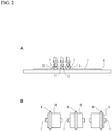
- the first stretching device 4 comprises the device disclosed in Japanese Patent No. 4,461,201 and therefore includes rollers 5, as shown in Fig. 2 .
- the plastic film 1 is fed longitudinally thereof and directed to a base 6.
- the rollers 5 are arranged widthwise of the plastic film 1, opposed to the plastic film 1 and the base 6 and supported by shafts 7 for rotation thereabout.
- the rollers 5 include tapered circumferential edges 8.
- the shafts 7 extend longitudinally of the plastic film 1.
- the first stretching device 4 further includes drive means by which the rollers 5 are moved and pushed downward so that the circumferential edges 8 should be pressed against the plastic film 1.
- the rollers 5 are moved widthwise of the plastic film 1 and rolled along the plastic film 1 to stretch the plastic film 1.
- the first stretching device 4 can select the number and type of rollers 5 to be moved downward, for adjustment of stretching amount of plastic film 1. It can increase the stretching amount to several times.
- the apparatus further includes a second optical sensor disposed at the path along which the plastic film 1 is fed, and detecting the positions at which the pattern A is printed on the plastic film 1 repeatedly, after correcting the print pitches P, to measure a sum of print pitches P(1)+P(2)+----+P(N) of a number of patterns A.
- a downstream optical sensor 9 is disposed at the path and downstream of the upstream optical sensor 2 and spaced from the upstream optical sensor 9 at a distance corresponding to an integral multiple of reference value P0 of print pitch, the downstream optical sensor 9 detecting the positions at which the pattern A is printed on the plastic film 1 repeatedly.
- a mark sensor is used as the downstream optical sensor 9 to detect the marks M or the positions, as in the case of the upstream optical sensor 2.
- the second optical sensor comprises the upstream and downstream optical sensors 2 and 9 to measure the sum of print pitches P(1)+ P(2)+----+P(N), as also described later.
- the apparatus further includes a second stretching device 10 disposed at the path and stretching the plastic film 1 after measuring the sum of print pitches P(1)+P(2)+----+P(N) and when the plastic film 1 is stopped temporarily, to correct the sum of print pitches P(1)+P(2)+----+P(N).
- the downstream optical sensor 9 is disposed at the path and downstream of the first stretching device 4 while the second stretching device 10 is disposed at the path and downstream of the downstream optical sensor 9.
- the second stretching device 10 has the same structure as the first stretching device 4 and therefore includes the rollers to stretch the plastic film 1. It can also select the number and type of the rollers to be moved downward, for adjustment of stretching amount of plastic film 1.
- the plastic film 1 then passes through dancer rollers 11 to be discharged.
- the apparatus further includes a control device 12 connected to the upstream optical sensor 2, the feeding rollers 3, the first stretching device 4, the downstream optical sensor 9 and the second stretching device 10.
- the feeding rollers 3 are operated by the control device 12.
- the first and second stretching device 4 and 10 are also operated by the control device 12.
- the feeding rollers 3 are rotated by the drive motor, as described previously. Accordingly, strictly speaking, the control device 12 is connected to the drive motor so that the feeding rollers 3 can be operated and rotated by the control device 12 and the drive motor.
- the first and second stretching devices 4 and 10 include the drive means by which the rollers 5 are moved to stretch the plastic film 1, as also described previously.
- the control device 12 is therefore connected to the drive means so that the rollers 5 can be operated and moved by the control device 12 and the drive means.
- the control device 12 comprises a computer.
- control device 12 is arranged to receive detecting signals transmitted from the upstream optical sensor 2.
- the feeding rollers 3 are operated by the control device 12 in response to the detecting signals transmitted from the upstream optical sensor 2 so that the plastic film 1 should be fed intermittently for the length corresponding to the print pitch P and stopped temporarily whenever being fed intermittently.
- the control device 12 is further arranged to measure the print pitches P individually to obtain measurement values in response to the detecting signals transmitted from the upstream optical sensor 2.
- the first stretching device 4 is operated by the control device 12 to stretch the plastic film 1 and correct the print pitches P individually when the measurement value is less than the reference value P0 to result in a difference P0-P exceeding a first predetermined value, between the measurement value and the reference value P0.
- the print pitch P is predetermined to be less than the reference value P0. It therefore often happens when measuring the print pitches P individually to obtain the measurement values that the measurement value is less than the reference value P0.
- the first stretching device is then operated to stretch the plastic film 1 and correct the print pitch when resulting in the difference P0 - P exceeding the first predetermined value.
- an additional optical sensor 13 is disposed at the path and upstream of the upstream optical sensor 2 and spaced from the upstream optical sensor 2 at a distance corresponding to the print pitch P or an integral multiple thereof.
- the plastic film 1 passes through a dancer roller 14 to be directed to the additional optical sensor 13 and the upstream optical sensor 2, the additional optical sensor 13 and the upstream optical sensor 2 detecting the positions at which the pattern A is printed on the plastic film 1 repeatedly.
- a mark sensor is used as the additional optical sensor 13 to detect the marks M or the positions.
- the first optical sensor comprises the upstream optical sensor 2 and the additional optical sensor 13 to measure the print pitches individually.
- the control device 12 is connected to the additional optical sensor 13 to receive detecting signals transmitted from the additional optical sensor 13.
- the control device 12 is arranged to measure the print pitches P individually to obtain the measurement values in response to the detecting signals transmitted from the additional optical sensor 13 and the upstream optical sensor 2.
- the additional optical sensor 13 and the upstream optical sensor 2 can detect the positions at which the pattern A is printed on the plastic film 1 repeatedly, when the plastic film 1 is stopped temporarily, to measure the print pitches P individually.
- the apparatus can measure the print pitches P exactly.
- the measurement value is then stored in the control device 12 when being less than the reference value to result in the difference P0-P exceeding the first predetermined value, the plastic film 1 including a portion concerned with the measurement value.
- the first stretching device 4 is then operated by the control device 12 to stretch the plastic film 1 and correct the print pitch P when the plastic film 1 is fed by the feeding rollers 3 and the concerned portion reaches the first stretching device 4.
- the control device 12 is arranged to recognize if the print pitch P contains a short or excess correcting amount after correcting.
- the short or excess correcting amount is stored in the control device 12 and then cleared by the measurement value of next print pitch P to obtain a cleared value.
- the first stretching device 4 is operated by the difference between the cleared value, which is used as the measurement value, and the reference value P0.
- the first stretching device 4 includes the rollers 5 for adjustment of stretching amount of plastic film 1, as described previously. It can increase the stretching amount to several times. The first stretching device 4 can therefore stretch the plastic film 1 by a minimum stretching amount d, a double stretching amount 2d or a triple stretching amount 3d.
- the first predetermined value comprises the minimum stretching amount d predetermined in the first stretching device 4. The first stretching device 4 therefore stretches the plastic film 1 to correct the print pitch P when resulting in the difference P0-P exceeding the minimum stretching amount d.
- the control device 12 is arranged to stretch the plastic film 1 by the minimum stretching amount d when resulting in the difference P0-P not exceeding the double stretching amount 2d but exceeding the minimum stretching amount d after measuring the print pitch P.
- the control device 12 is further arranged to stretch the plastic film 1 by the double stretching amount 2d when resulting in the difference P0-P not exceeding the triple stretching amount 3d but exceeding the double stretching amount 2d.
- the control device 12 is further arranged not to stretch the plastic film 1 and correct the print pitch P when resulting in the difference P0-P not exceeding the minimum stretching amount d.
- the print pitch P must therefore be shortage by an uncorrected amount less than the minimum stretching amount d after correcting.
- the control device 12 is arranged to recognize if the print pitch P is shortage by the uncorrected amount after correcting.
- the uncorrected amount is stored in the control device 12 and then subtracted from the measurement value of next print pitch P to obtain a subtracted value.
- the first stretching device 4 is operated by the difference between the subtracted value, which is used as the measurement value, and the reference value V0, to stretch the plastic film 1.
- control device 12 is arranged to stretch the plastic film 1 by the minimum stretching amount d when resulting in the difference P0-P not exceeding the double stretching amount 2d but exceeding the minimum stretching amount d, as described previously. It is also arranged to stretch the plastic film 1 by the double stretching amount 2d when resulting in the difference P0-P not exceeding the triple stretching amount 3d but exceeding the double stretching amount 2d.
- the print pitch P must therefore contain a short correcting amount after correcting.
- the control device 12 is arranged to recognize if the print pitch P contains the short correcting amount.
- the short correcting amount is stored in the control device 12 and then subtracted from the measurement value of next print pitch P to obtain a subtracted value.
- the first stretching device 4 is operated by the difference between the subtracted value, which is used as the measurement value, and the reference value P0, to stretch the plastic film 1.
- the first predetermined value may comprise a predetermined amount less than the minimum stretching amount d of first stretching device 4.
- the first predetermined value may be small as much as possible. It may be zero.
- the first stretching device 4 stretches the plastic film 1 by the minimum stretching amount when resulting in the difference P0-P not exceeding the minimum stretching amount d. It stretches the plastic film 1 by the double stretching amount 2d when resulting in the difference P0-P not exceeding the double stretching amount 2d but exceeding the minimum stretching amount d. It stretches the plastic film 1 by the triple stretching amount 3d when resulting in the difference P0-P not exceeding the triple stretching amount 3d but exceeding the double stretching amount 2d.
- the print pitch P in contraries, the print pitch P must contain an excess correcting amount after correcting.
- the control device 12 is therefore arranged to recognize if the print pitch P contains the excess correcting amount.
- the excess correcting amount is stored in the control device 12 and then added to the measurement value of next print pitch P to obtain an added value.
- the first stretching device 4 is operated by the difference between the added value, which is used as the measurement value, and the reference value P0.
- control device 12 is arranged to receive a detecting signal transmitted from the downstream optical sensor 9.
- the control device 12 is further arranged to measure the sum of print pitches P(1)+P(2)+----+ P(N) of the number of patterns A to obtain the additional measurement value in response to the detecting signals transmitted from the upstream and downstream optical sensors 2 and 9.
- the sum of print pitches P(1)+P(2)+----+ P(N) exists between the upstream and downstream optical sensors 2 and 9.
- the reference value P0 ⁇ N exists between the upstream and downstream optical sensors 2 and 9.
- the second stretching device 10 is then operated by the control device 12 to stretch the plastic film 1 and correct the sum of print pitches P(1) +P(2)+----+P(N) when the plastic film 1 is fed by the feeding rollers 3 and the concerned portion reach the second stretching device 10 and when the plastic film 1 is stopped temporarily.
- the first stretching device 4 is spaced from the upstream optical sensor 2 at a distance corresponding to or less than the print pitch P of plastic film 1.
- the additional optical sensor 13 and the upstream optical sensor 2 are used to measure the print pitches P individually, the plastic film 1 being fed by the feeding rollers 3, the first stretching device 4 stretching the plastic film 1 to correct the print pitches individually.
- the upstream and downstream optical sensors 2 and 9 are then used to measure the sum of print pitches P(1)+P(2)+ ----+P(N).
- the sum of print pitches P(1)+P(2)+----+P(N) is therefore composed of the print pitches P interposed between the upstream and downstream optical sensors 2 and 9 for measurement after correcting respectively.
- the print pitch P may be considerable small. In this case, it may be difficult to make the first stretching device 4 spaced from the upstream optical sensor at the distance corresponding to or less than the print pitch P of plastic film 1.
- the sum of print pitches P(1)+P(2)+----+P(N) can therefore not be composed of all of the print pitches P after correcting respectively.
- the sum of print pitches P(1)+P(2)+----+P(N) contains print pitches P before correcting.
- the additional optical sensor 13 and the upstream optical sensor 2 can measure the print pitches P of plastic film 1 to calculate the uncorrected amount thereof.
- the upstream and downstream optical sensors 2 and 9 can measure the sum of print pitches P(1)+P(2)+----+P(N) to obtain a provisional value. The uncorrected amount can then be added to the provisional value to be used as the measurement value.
- control device 12 is arranged to recognize if the sum of print pitches P(1)+P(2)+----+P(N) contains a short or excess correcting amount after correcting.
- the short or excess correcting amount is stored in the control device 12 and then cleared by the measurement value of next sum of print pitches P(1)+P(2)+----+P(N) to obtain a cleared value.
- the second stretching device 10 includes the rollers 5 for adjustment of stretching amount of plastic film 1, as in the case of the first stretching device 4.
- the second stretching device 10 can stretch the plastic film 1 by a minimum stretching amount d, a double stretching amount 2d or a triple stretching amount 3d.
- the second predetermined value comprises the minimum stretching amount d predetermined in the second stretching device 10.
- the sum of print pitches P(1) +P(2)+----P(N) must therefore be shortage by an uncorrected amount less than the minimum stretching amount d.
- control device 12 is arranged to recognize if the sum of print pitches P(1)+P(2) +----+P(N) is shortage by the uncorrected amount.
- the uncorrected amount is stored in the control device 12.
- the uncorrected amount is then subtracted from the measurement value of next sum of print pitches P(1)+P(2)+ ----+P(N) to obtain a subtracted value.
- the sum of print pitches P(1)+P(2)+----+P(N) must therefore contain a short correcting amount after correcting. Under the circumstances, the control device 12 is arranged to recognize if the sum of print pitches P(1)+P(2)+----+P(N) contains the short correcting amount.
- the short correcting amount is stored in the control device 12 and then subtracted from the measurement value of next sum of print pitches P(1)+P(2)+----+ P(N) to obtain a subtracted value.
- the second stretching device 10 is operated by a difference between the subtracted value, which is used as the measurement value, and the reference value P0 ⁇ N, to stretch the plastic film 1.
- the second predetermined value may comprise a predetermined amount less than the minimum stretching amount d of second stretching device 10.
- the second predetermined value may be small as much as possible. It may be zero.
- the sum of print pitches P(1)+P(2)+-+P(N) must contain an excess correcting amount after correcting.
- the control device is therefore arranged to recognize if the sum of print pitches P(1)+P(2)+ ----+P(N) contains the excess correcting amount.
- the excess correcting amount is stored in the control device 12 and then added to the measurement value of next sum of print pitches P(1)+P(2)+----+P(N) to obtain an added value.
- the second stretching device 10 is operated by the difference between the added value, which is used as the measurement value, and the reference value P0 ⁇ N.
- the second stretching device 10 may be disposed to stretch the plastic film 1 at any portion concerned with the sum of print pitches P(1)+P(2)+--P(N) after measuring. It may be arranged to stretch the plastic film 1 once at the same portion or two or three times at two or three portions when stretching it by the double or triple stretching amount.
- the apparatus may be arranged to measure the sum of print pitches P(1) +P(2)+----+P(N) whenever the plastic film 1 is fed intermittently. It may be arranged to measure the sum of print pitches P(1)+P(2)+----+P(N) whenever the plastic film 1 is fed intermittently several times. It may be arranged to measure the sum of print pitches P(1)+P(2)+----P(N) whenever the plastic film 1 is fed intermittently a number of times corresponding to the print pitches P(1)+P(2)+----+P(N) in the sum.
- the apparatuses 15 for correcting print pitches P at which patterns A are printed on plastic films 1 repeatedly, as shown in Fig. 3 .
- the apparatuses are incorporated in a machine including guide rollers 16, feeding rollers 17, a heat seal device 18 and 19 and a cross cutter 20.
- the plastic films 1 are directed to the guide rollers 16 to be superposed with each other after correcting the print pitches P.
- the plastic films 1 are then directed to the feeding rollers 17 by which the plastic films 1 is fed intermittently for a length corresponding to the print pitch P and stopped temporarily whenever being fed intermittently.
- the plastic films 1 are heat sealed with each other by the heat seal device 18 and 19 and cross cut by the cross cutter 20 whenever being fed intermittently and when stopped temporarily, to successively make plastic bags.
- the heat seal device comprises longitudinal and cross seal devices 18 and 19.
- the plastic films 1 are heat sealed by the longitudinal seal device 18 longitudinally thereof and heat sealed by the cross seal device 19 widthwise of the plastic films 1.
- the plastic films 1 are then cross cut by the cross cutter 20 to successively make the plastic bags.
- the additional optical sensor 13 and the upstream optical sensor 2 are used to measure the print pitches P individually.
- the first stretching device 4 then stretches the plastic film 1 after measuring the print pitches P, to correct the print pitches P individually. It is intended to correct the print pitch P toward the reference value P0.
- the upstream and downstream optical sensors 2 and 9 are used to measure the sum of print pitches P(1)+P(2)+----+P(N) of a number of patterns A after correcting the print pitches P.
- the second stretching device 10 then stretches the plastic film 1 after measuring the sum of print pitches P(1) +P(2)+----+P(N), to correct the sum of print pitches P(1)+P(2)+--P(N), if necessary.
- the apparatus can therefore correct the print pitches P in a two-stage process. As a result, the apparatus can correct the print pitches P individually and exactly to keep them at the reference value P0 or a fixed value.
- the apparatus can therefore overcome the problem of discrepancy in pattern between the plastic films 1 due to the accumulated errors of print pitches when being incorporated in the machine for successively making the plastic bags.
- the plastic films 1 are superposed with each other, heat sealed with each other by the heat seal device 18 and 19 and then cross cut by the cross cutter 20, to successively make the plastic bags.
- the apparatus can further overcome the problem of print pitch fluctuated to make the plastic bag have a size changed, described previously in connection with the apparatus of Japanese Patent No. 4,121,722 .
- the heat seal devices 18 and 19 and the cross cutter 20 have not to be moved by a drive means for adjustment of position, not resulting in technical problems.
- the additional optical sensor 13, the upstream optical sensor 2 and the feeding rollers 3 are disposed at the path along which the plastic films 1 are fed, as in the case of the embodiment of Fig. 1 .
- the first and second stretching device comprises a single stretching device 21 disposed at the path and downstream of the upstream optical sensor 2 and feeding rollers 2.
- the downstream optical sensor 9 is disposed at the path and downstream of the single stretching device 21.
- the single stretching device 21 comprises a plastic film stretching device stretching the plastic film 1 longitudinally thereof.
- the plastic film stretching device 21 has the same structure as the devices 4 and 10 of Fig. 1 .
- the plastic film stretching device can therefore stretch the plastic film 1 by the minimum stretching amount d, the double stretching amount 2d or the triple stretching amount 3d.
- the downstream optical sensor 9 is spaced from the upstream optical sensor 2 at the distance corresponding to the integral multiple of reference value P0 of print pitch.
- the control device 12 is connected to the additional optical sensor 13, the upstream optical sensor 2, the feeding rollers 3, the plastic film stretching device 21 and the downstream optical sensor 9.
- control device 12 receives the detecting signals transmitted from the upstream optical sensor 2.
- the feeding rollers 3 are operated by the control device 12 in response to the detecting signals transmitted from the upstream optical sensor 2 so that the plastic films 1 should be fed intermittently for the length corresponding to the print pitch P and stopped temporarily whenever being fed intermittently.
- the control device 12 further receives the detecting signals transmitted from the additional optical sensor 13.
- the control device 12 measures the print pitches P individually to obtain the measurement values in response to the detecting signals transmitted from the additional optical sensor 13 and the upstream optical sensor 2.
- the plastic film stretching device 21 is operated by the control device 12 to stretch the plastic film 1 and correct the print pitches P individually when the measurement value is less than the reference value P0 to result in the difference P0-P exceeding the first predetermined value and when the plastic film 1 is stopped temporarily.
- the first predetermined value comprises the minimum stretching amount d of plastic film stretching device 21.
- the first predetermined value may comprise the predetermined value less than the minimum stretching amount d of plastic film stretching device 21.
- the first predetermined value may be small as much as possible. It may be zero, as also in the embodiment of Fig. 1 .
- the control device 12 receives the detecting signals transmitted from the downward optical sensor 9.
- the control device 12 measures the sum of print pitches P(1)+P(2)+----+P(N) of the number of patterns A to obtain the additional measurement value in response to the detecting signals transmitted from the upstream and downstream optical sensors 2 and 9.
- the second predetermined value comprises the minimum stretching amount d of plastic film stretching device 21.
- the second predetermined value may comprise the predetermined amount less than the minimum stretching amount d of plastic film stretching device 21.
- the second predetermined value may be small as much as possible. It may be zero.
- the sum of print pitches P(1)+P(2)+-+P(N) is composed of the print pitches P interposed between the upstream and downstream optical sensors 2 and 9 for measurement after correcting respectively.
- the sum of print pitches P(1)+P(2)+----+P(N) may contain print pitches P before correcting.
- the upstream and downstream optical sensors 2 and 13 may measure the sum of print pitches P(1)+P(2)+-+P(N) to obtain a provisional value. The uncorrected amount is then be added to the provisional amount to be used as the measurement value.
- the plastic film stretching device 21 may stretch the plastic film 1 to correct the print pitches P or the sum of print pitches P(1)+P(2)+----+ P(N) after the additional optical sensor 13 and the upstream optical sensor 2 measure the print pitches P of plastic film 1 or the upstream and downstream optical sensors 2 and 9 measure the sum of print pitches P(1)+P(2)+----+ P(N).
- the plastic film stretching device 21 may be intended to correct the print pitch P and the sum of print pitches P(1)+P(2)+----+P(N) at the same time.
- the control device 12 is arranged to recognize if the sum of print pitches P(1)+P(2)+----+P(N) contains a short or excess correcting amount after correcting.
- the short or excess correcting amount is stored in the control device 12 and then cleared by the measurement value of next sum of print pitches P(1)+P(2)+----+P(N) to obtain the cleared value.
- the sum of print pitches P(1)+P(2)+----+P(N) may contain the short correcting amount, after correcting.
- the short correcting amount is subtracted from the measurement value of next sum of print pitches P(1)+P(2)+----P(N) to obtain the subtracted value.
- the sum of print pitches P(1)+P(2)+----+P(N) may contain the excess correcting amount, after correcting. In this case, the excess correcting amount is added to the measurement value of next sum of print pitches P(1)+P(2)+----P(N) to obtain the added value.
- the sum of print pitches P(1)+P(2)+----+P(N) may be shortage by the uncorrected amount less than the minimum stretching amount d.
- the uncorrected amount should be subtracted from the measurement value of next sum of print pitches P(1)+P(2)+----+P(N) to obtain the subtracted value.
- the apparatus may be arranged to measure the sum of print pitches P(1) +P(2)+----+P(N) whenever the plastic film 1 is fed intermittently. It may be arranged to measure the sum of print pitches P(1)+P(2)+----+P(N) whenever the plastic film 1 is fed intermittently several times. It may be arranged to measure the sum of print pitches P(1)+P(2)+----+P(N) whenever the plastic film 1 is fed intermittently a number of times corresponding to the print pitches P(1)+P(2)+----+P(N) in the sum.
- a plurality of the apparatuses are incorporated in a machine in which plastic films 1 are superposed with each other after correcting the print pitches P, as in the case of the embodiment of Figs. 1 to 3 .
- the plastic films 1 are heat sealed with each other by the heat seal device and then cross cut by the cross cutter to successively make the plastic bags.
- the plastic film stretching device 21 stretches the plastic film 1 after measuring the print pitches P, to correct the print pitches P individually.
- the upstream and downstream optical sensors 2 and 9 are used to measure the sum of print pitches P(1)+P(2)+--+P(N) of the number of patterns A after correcting the print pitches P.
- the plastic film stretching device 21 then stretches the plastic film 1 to correct the sum of print pitches P(1)+P(2)+----+P(N), if necessary.
- the apparatus can therefore correct the print pitches P in a two-stage process.
- the apparatus can correct the print pitches P individually and exactly to keep them at the reference value P0 or a fixed value.
Landscapes
- Engineering & Computer Science (AREA)
- Mechanical Engineering (AREA)
- Shaping By String And By Release Of Stress In Plastics And The Like (AREA)
- Controlling Rewinding, Feeding, Winding, Or Abnormalities Of Webs (AREA)
- Making Paper Articles (AREA)
- Registering, Tensioning, Guiding Webs, And Rollers Therefor (AREA)
- Polarising Elements (AREA)
- Length Measuring Devices By Optical Means (AREA)
- Application Of Or Painting With Fluid Materials (AREA)
Claims (7)
- Vorrichtung zum Korrigieren von Druckabständen (P), mit denen ein Muster (A) wiederholt auf eine Kunststofffolie (1) gedruckt wird, welche Vorrichtung aufweist:Zuführungsrollen (3), durch die die Kunststofffolie (1) intermittierend über eine Länge entsprechend dem Druckabstand (P) zugeführt und vorübergehend angehalten wird, wenn sie intermittierend zugeführt wird;welche Vorrichtung gekennzeichnet ist durcheinen ersten optischen Sensor (2), der auf einem Pfad, entlang dessen die Kunststofffolie (1) intermittierend zugeführt wird, angeordnet ist und Positionen erfasst, an denen das Muster (A) wiederholt auf die Kunststofffolie (1) gedruckt wird, um die Druckabstände (P) individuell zu messen;eine erste Streckvorrichtung (4), die in dem Pfad und stromabwärts des ersten optischen Sensors (2) mit Bezug auf eine Richtung, in der die Kunststofffolie (1) zugeführt wird, angeordnet ist und die Kunststofffolie (1) nach dem Messen des Druckabstands (P) und wenn die Kunststofffolie (1) vorübergehend angehalten ist, streckt, um die Druckabstände (P) individuell zu korrigieren;einen zweiten optischen Sensor (2, 9), der auf dem Pfad angeordnet ist und die Positionen nach dem Korrigieren der Druckabstände (P) erfasst, um eine Summe von Druckabständen (P1+P2+----+PN) einer Anzahl von Mustern (A) zu messen;eine zweite Streckvorrichtung (10), die in dem Pfad angeordnet ist und die Kunststofffolie (1) nach dem Messen der Summe von Druckabständen (P1+P2+----+PN) und wenn die Kunststofffolie (1) vorübergehend angehalten ist, streckt, um die Summe von Druckabständen (P1+P2+--+PN) zu korrigieren; undeine Steuervorrichtung (12), die angeordnet ist zum individuellen Messen der Druckabstände (P) und zum Erhalten von Messwerten als Antwort auf von dem ersten optischen Sensor (2) gesendete Erfassungssignale, wobei die erste Streckvorrichtung (4) durch die Steuervorrichtung (12) betätigt wird, um die Kunststofffolie (1) zu strecken und den Druckabstand (P) zu korrigieren, wenn der Messwert kleiner als ein Bezugswert (P0) ist, um eine Differenz (PO-P), die einen vorbestimmten Wert überschreitet, zwischen dem Messwert und dem Bezugswert (P0) zu ergeben,die Steuervorrichtung (12) angeordnet ist zum Messen der Summe von Druckabständen P1+P2+----+PN) der Anzahl von Mustern (A), um einen Messwert als Antwort auf ein von dem zweiten optischen Sensor (9) gesendetes Erfassungssignal zu erhalten, wobei die zweite Streckvorrichtung (10) durch die Steuervorrichtung (12) betätigt wird, um die Kunststofffolie (1) zu strecken und die Summe von Druckabständen (P1+P2+----+PN) zu korrigieren, wenn der Messwert kleiner als ein Bezugswert (P0×N) ist, um eine Differenz (S=ΣSi), die einen vorbestimmten Wert überschreitet, zwischen dem Messwert und dem Bezugswert (P0×N) zu ergeben,wobei der erste optische Sensor einen stromaufwärtsseitigen optischen Sensor (2), der auf dem Pfad angeordnet ist, aufweist, und der zweite optische Sensor den stromaufwärtsseitigen optischen Sensor und einen stromabwärtsseitigen optischen Sensor (9) aufweist, wobei der stromabwärtsseitige optische Sensor (9) auf dem optischen Pfad und stromabwärts des stromaufwärtsseitigen optischen Sensors (2) mit Bezug auf die Richtung, in der die Kunststofffolie (1) zugeführt wird, angeordnet ist und einen Abstand von dem stromaufwärtsseitigen optischen Sensor (2) entsprechend einem integralen Mehrfachen des Bezugswerts (P0) von Druckabständen hat, und der stromaufwärtsseitige und der stromabwärtsseitige optische Sensor (2, 9) die Positionen erfassen, an denen das Muster (A) wiederholt auf die Kunststofffolie (1) gedruckt wird,und wobei die Zuführungsrollen (3) auf dem Pfad und stromabwärts des stromaufwärtsseitigen optischen Sensors (2) mit Bezug auf die Richtung, in der die Kunststofffolie (2) zugeführt wird, angeordnet sind, die Zuführungsrollen (3) durch die Steuervorrichtung (12) als Antwort auf die von dem stromaufwärtsseitigen optischen Sensor (2) gesendeten Erfassungssignale so betätigt werden, dass die Kunststofffolie (1) um die Länge entsprechend dem Druckabstand (P) intermittierend zugeführt wird.
- Vorrichtung nach Anspruch 1, bei der der vorbestimmte Wert einen minimalen Streckbetrag (d), der in der ersten Streckvorrichtung (4) vorbestimmt ist, aufweist, die erste Streckvorrichtung (4) durch die Steuervorrichtung (12) betätigt wird, um die Kunststofffolie (1) zu strecken, wenn der Messwert kleiner als der Bezugswert (P0) ist, um die Differenz (PO-P), die den minimalen Streckbetrag (d) überschreitet, zu ergeben, die Steuervorrichtung (12) angeordnet ist zum Erkennen, wenn der Druckabstand (P) einen Fehlbetrag um einen nicht korrigierten Betrag, der kleiner als der minimale Streckbetrag (d) nach dem Korrigieren ist, hat, der nicht korrigierte Betrag in der Steuervorrichtung (12) gespeichert und dann von dem Messwert des nächsten Druckabstands (P) subtrahiert wird, um einen subtrahierten Wert zu erhalten, und wobei die erste Streckvorrichtung (4) durch die Differenz zwischen dem subtrahierten Wert, der als der Messwert verwendet wird, und dem Bezugswert (P0) betätigt wird.
- Vorrichtung nach Anspruch 1, bei der der vorbestimmte Wert einen minimalen Streckbetrag (d), der in der zweiten Streckvorrichtung (10) vorbestimmt ist, aufweist, die zweite Streckvorrichtung (10) durch die Steuervorrichtung (12) betätigt wird, um die Kunststofffolie (1) zu strecken, wenn der Messwert kleiner als der Bezugswert (P0×N) ist, um die Differenz (S=ΣSi), die den minimalen Streckbetrag (d) überschreitet, zu ergeben, die Steuervorrichtung (12) angeordnet ist, zu erkennen, wenn die Summe von Druckabständen (P1+P2+----+PN) einen Fehlbetrag um einen nicht korrigierten Betrag, der kleiner als der minimale Streckbetrag (d) nach dem Korrigieren ist, hat, der nicht korrigierte Betrag in der Steuervorrichtung (12) gespeichert und dann von dem Messwert der nächsten Summe von Druckabständen (P1+P2+----+PN) subtrahiert wird, um einen subtrahierten Wert zu erhalten, und die zweite Streckvorrichtung (10) durch die Differenz (S=ΣSi) zwischen dem subtrahierten Wert, der als der Messwert verwendet wird, und dem Bezugswert (P0×N) betätigt wird.
- Vorrichtung nach Anspruch 1, bei der ein zusätzlicher optischer Sensor (13) auf dem Pfad und stromaufwärts des stromaufwärtsseitigen optischen Sensors (2) mit Bezug auf die Richtung, in der die Kunststofffolie (1) zugeführt wird, und in einem Abstand von dem stromaufwärtsseitigen optischen Sensor (2) entsprechend dem Druckabstand (P) oder einem integralen Mehrfachen hiervon angeordnet ist, wobei der zusätzliche optische Sensor (13) die Positionen erfasst, an denen das Muster (A) wiederholt auf die Kunststofffolie (1) gedruckt wird, und der erste optische Sensor den stromaufwärtsseitigen optischen Sensor (2) und den zusätzlichen optischen Sensor (13) zum individuellen Messen der Druckabstände (P) aufweist.
- Vorrichtung nach Anspruch 1, bei der die erste Streckvorrichtung (4) stromabwärts des stromaufwärtsseitigen optischen Sensors (2) mit Bezug auf die Richtung, in der die Kunststofffolie (1) zugeführt wird, angeordnet ist, der stromabwärtsseitige optische Sensor (9) stromabwärts der ersten Streckvorrichtung (4) mit Bezug auf die Richtung, in der die Kunststofffolie (1) zugeführt wird, angeordnet ist, und die zweite Streckvorrichtung (10) stromabwärts des stromabwärtsseitigen optischen Sensors (9) mit Bezug auf die Richtung, in der die Kunststofffolie (1) zugeführt wird, angeordnet ist.
- Vorrichtung nach Anspruch 1, bei der die Vorrichtung in einer Maschine aufgenommen ist, die eine Heißversiegelungsvorrichtung (18, 19) und eine Querschneidvorrichtung (2) enthält, die Kunststofffolien (1) nach dem Korrigieren der Druckabstände (P) übereinandergelegt werden, die Kunststofffolien (1) dann durch die Heißversiegelungsvorrichtung (18, 19) miteinander heißversiegelt werden und durch die Querschneidvorrichtung (20) quergeschnitten werden, um aufeinanderfolgend Kunststoffbeutel herzustellen.
- Vorrichtung zum Korrigieren von Druckabständen (P), mit denen ein Muster (A) wiederholt auf eine Kunststofffolie (1) gedruckt wird, wobei die Kunststofffolie (1) in ihrer Längsrichtung zugeführt wird, welche Vorrichtung aufweist:einen stromaufwärtsseitigen optischen Sensor (2), der auf einem Pfad, entlang dessen die Kunststofffolie (1) zugeführt wird, angeordnet ist, um Positionen zu erfassen, an denen das Muster (A) wiederholt auf die Kunststofffolie (1) aufgedruckt wird; undZuführungsrollen (3), die auf dem Pfad und stromabwärts des stromaufwärtsseitigen optischen Sensors (2) mit Bezug auf eine Richtung, in der die Kunststofffolie (1) zugeführt wird, angeordnet sind, wobei die Kunststofffolie (1) durch die Zuführungsrollen (3) zugeführt wird;welche Vorrichtung gekennzeichnet ist durcheine Kunststofffolien-Streckvorrichtung (21), die in dem Pfad und stromabwärts des stromaufwärtsseitigen optischen Sensors (2) mit Bezug auf die Richtung, in der die Kunststofffolie (1) zugeführt wird, angeordnet ist, um die Kunststofffolie (1) zu strecken;einen stromabwärtsseitigen optischen Sensor (9), der auf dem Pfad und stromabwärts der Zuführungsrollen (3) und der Kunststofffolien-Streckvorrichtung (21) mit Bezug auf die Richtung, in der die Kunststofffolie (1) zugeführt wird, angeordnet ist und einen Abstand von dem stromaufwärtsseitigen optischen Sensor (4) entsprechend einem integralen Mehrfachen eines Bezugswerts (P0) des Druckabstands aufweist, um die Positionen zu erfassen, an denen das Muster (A) wiederholt auf die Kunststofffolie (1) gedruckt wird; undeine Steuervorrichtung (12), die angeordnet ist, Erfassungssignale, die von dem stromaufwärtsseitigen und dem stromabwärtsseitigen optischen Sensor (2, 9) gesendet wurden, zu empfangen, wobei die Zuführungsrollen (3) durch die Steuervorrichtung (12) als Antwort auf die von dem stromaufwärtsseitigen optischen Sensor (2) gesendeten Erfassungssignale so betätigt werden, dass die Kunststofffolie (1) intermittierend über eine Länge entsprechend dem Druckabstand (P) zugeführt und vorübergehend angehalten werden, wenn sie intermittierend zugeführt wird, die Steuervorrichtung (12) weiterhin angeordnet ist, die Druckabstände (P) individuell zu messen, um Messwerte als Antwort auf die von dem stromaufwärtsseitigen optischen Sensor (2) gesendeten Erfassungssignale zu erhalten, die Kunststofffolien-Streckvorrichtung (21) durch die Steuervorrichtung (12) betätigt wird, um die Kunststofffolie (1) zu strecken und die Druckabstände (P) individuell zu korrigieren, wenn der Messwert kleiner als ein Bezugswert (P0) des Druckabstands ist, um eine Differenz (PO-P), die einen ersten vorbestimmten Wert überschreitet, und wenn die Kunststofffolie (1) vorübergehend angehalten wird, zu ergeben, die Steuervorrichtung (12) weiterhin angeordnet ist zum Messen einer Summe von Druckabständen (P1+P2+----+PN) einer Anzahl von Mustern (A), um einen zusätzlichen Messwert als Antwort auf die von dem stromaufwärtsseitigen und dem stromabwärtsseitigen optischen Sensor (2, 9) gesendeten Erfassungssignale zu erhalten, die Kunststofffolien-Streckvorrichtung (21) durch die Steuervorrichtung (12) betätigt wird, um die Kunststofffolie (1) zu strecken und die Summe von Druckabständen (P1+P2+----+PN) zu korrigieren, wenn der zusätzliche Messwert kleiner als ein Bezugswert (P0×N) der Summe von Druckabständen ist, um eine Differenz (S=ΣSi), die einen zweiten vorbestimmten Wert überschreitet, und wenn die Kunststofffolie (1) vorübergehend angehalten ist, zu ergeben.
Applications Claiming Priority (1)
| Application Number | Priority Date | Filing Date | Title |
|---|---|---|---|
| JP2012223404A JP5346113B1 (ja) | 2012-10-05 | 2012-10-05 | プラスチックフィルムの印刷ピッチ矯正装置 |
Publications (2)
| Publication Number | Publication Date |
|---|---|
| EP2716457A1 EP2716457A1 (de) | 2014-04-09 |
| EP2716457B1 true EP2716457B1 (de) | 2019-02-20 |
Family
ID=49382200
Family Applications (1)
| Application Number | Title | Priority Date | Filing Date |
|---|---|---|---|
| EP13187332.5A Active EP2716457B1 (de) | 2012-10-05 | 2013-10-04 | Druck-Pitch-Korrekturvorrichtung für Kunststofffolie |
Country Status (8)
| Country | Link |
|---|---|
| US (1) | US9238326B2 (de) |
| EP (1) | EP2716457B1 (de) |
| JP (1) | JP5346113B1 (de) |
| CN (1) | CN103707633B (de) |
| AU (1) | AU2013237677B2 (de) |
| BR (1) | BR102013025735A2 (de) |
| CA (1) | CA2829675C (de) |
| RU (1) | RU2542550C1 (de) |
Families Citing this family (6)
| Publication number | Priority date | Publication date | Assignee | Title |
|---|---|---|---|---|
| CN106079851A (zh) * | 2016-06-05 | 2016-11-09 | 镇江立昌智能装备有限公司 | 凹版印刷机安全装置 |
| JP6931885B2 (ja) * | 2017-05-29 | 2021-09-08 | 株式会社New IWASHO | 製袋機 |
| WO2020026620A1 (ja) | 2018-08-02 | 2020-02-06 | トタニ技研工業株式会社 | 間欠搬送装置 |
| CN110789179B (zh) * | 2019-09-25 | 2021-08-20 | 浙江天之元物流科技有限公司 | 包装袋半自动化生产工艺 |
| CN114728485B (zh) * | 2019-12-11 | 2023-08-25 | 户谷技研工业株式会社 | 位置对准装置 |
| CN116604880B (zh) * | 2023-06-15 | 2023-09-12 | 成都乐美纸制品有限公司 | 一种光标定位碗底的印刷标签切割机床以及识别切割方法 |
Family Cites Families (13)
| Publication number | Priority date | Publication date | Assignee | Title |
|---|---|---|---|---|
| JP2886960B2 (ja) * | 1990-09-12 | 1999-04-26 | キヤノン株式会社 | 領域指定装置 |
| US5470300A (en) * | 1992-09-09 | 1995-11-28 | Ro-An Industries Corporation | Web registration system and method |
| US7022057B2 (en) | 2000-12-20 | 2006-04-04 | Water-Line Sa | Device for manufacturing packing bags |
| JP4121722B2 (ja) * | 2001-08-07 | 2008-07-23 | トタニ技研工業株式会社 | プラスチックフィルムの印刷ピッチ矯正装置 |
| JP2003326616A (ja) * | 2002-05-15 | 2003-11-19 | Totani Corp | 製袋機 |
| JP4402872B2 (ja) * | 2002-10-18 | 2010-01-20 | トタニ技研工業株式会社 | 製袋機 |
| JP3872449B2 (ja) * | 2003-06-09 | 2007-01-24 | トタニ技研工業株式会社 | プラスチックフィルムの印刷ピッチ矯正装置 |
| JP2005201783A (ja) * | 2004-01-16 | 2005-07-28 | Sumitomo Chemical Co Ltd | 枚葉フィルムの欠陥検査装置 |
| AU2009238919B2 (en) * | 2008-04-24 | 2012-11-29 | Totani Corporation | Plastic film stretching apparatus |
| CN102066219B (zh) * | 2008-07-11 | 2013-07-24 | 户谷技研工业株式会社 | 塑料薄膜延伸装置 |
| JP4819110B2 (ja) * | 2008-10-28 | 2011-11-24 | トタニ技研工業株式会社 | 製袋機 |
| CN102180376B (zh) * | 2011-02-22 | 2013-01-30 | 临海市锦铮机械有限公司 | 自动矫正胶带机 |
| JP4902796B1 (ja) * | 2011-03-30 | 2012-03-21 | トタニ技研工業株式会社 | 製袋機 |
-
2012
- 2012-10-05 JP JP2012223404A patent/JP5346113B1/ja active Active
-
2013
- 2013-09-29 CN CN201310454642.4A patent/CN103707633B/zh active Active
- 2013-10-02 CA CA2829675A patent/CA2829675C/en not_active Expired - Fee Related
- 2013-10-02 US US14/044,156 patent/US9238326B2/en active Active
- 2013-10-02 AU AU2013237677A patent/AU2013237677B2/en not_active Ceased
- 2013-10-03 RU RU2013144564/12A patent/RU2542550C1/ru not_active IP Right Cessation
- 2013-10-04 EP EP13187332.5A patent/EP2716457B1/de active Active
- 2013-10-04 BR BRBR102013025735-4A patent/BR102013025735A2/pt active Search and Examination
Non-Patent Citations (1)
| Title |
|---|
| None * |
Also Published As
| Publication number | Publication date |
|---|---|
| AU2013237677A1 (en) | 2014-04-24 |
| US20140099394A1 (en) | 2014-04-10 |
| CA2829675C (en) | 2016-07-12 |
| CN103707633A (zh) | 2014-04-09 |
| JP2014073904A (ja) | 2014-04-24 |
| JP5346113B1 (ja) | 2013-11-20 |
| US9238326B2 (en) | 2016-01-19 |
| BR102013025735A2 (pt) | 2014-11-11 |
| AU2013237677B2 (en) | 2015-11-19 |
| CA2829675A1 (en) | 2014-04-05 |
| CN103707633B (zh) | 2016-06-29 |
| RU2542550C1 (ru) | 2015-02-20 |
| EP2716457A1 (de) | 2014-04-09 |
Similar Documents
| Publication | Publication Date | Title |
|---|---|---|
| EP2716457B1 (de) | Druck-Pitch-Korrekturvorrichtung für Kunststofffolie | |
| US5361960A (en) | Off-line web finishing system with splice and missing mark stability | |
| JP4112709B2 (ja) | バックル・プレート折りステーション並びにその制御方法 | |
| EP0260498A1 (de) | Regulierung von Seitenabweichungen eines Bandes | |
| EP3831753B1 (de) | Intermittierende transportvorrichtung | |
| US7762301B2 (en) | Device for the precise positional joining of two material webs | |
| JP2000296644A (ja) | ブランクに印刷を施す方法と装置 | |
| US10029454B2 (en) | Methods and apparatuses for producing a newspaper comprising aligning preprinted images to the operations of a press and modifying the cutoff length of the preprinted images | |
| US6220134B1 (en) | Device for separating material web sections from a moving endless material web | |
| JP2017226128A (ja) | 製袋機およびその制御方法 | |
| US20050239621A1 (en) | Method for monitoring the position of a sheet transported in a folding machine | |
| US6164200A (en) | Apparatus for imprinting an unmarked endless foil | |
| EP3463912B1 (de) | Automatisches verfahren und vorrichtung zum schneiden von substraten mit gedruckten bildern | |
| EP2840048A2 (de) | System und Verfahren zur Messung der ungespannten Produktlänge einer Bahn während der Herstellung | |
| JP6536031B2 (ja) | 製袋機およびその制御方法 | |
| US7640856B2 (en) | Method for controlling the feeding of a web substrate into a printing press | |
| JP2005001114A (ja) | プラスチックフィルムの印刷ピッチ矯正装置 | |
| JP2014231174A (ja) | 製袋機および製袋方法 | |
| US20140311367A1 (en) | System and method for dynamic measurement of dimension change for a sheet | |
| JP2008039714A (ja) | 絵柄ピッチ計測装置 | |
| JP2017100266A (ja) | 物体の位置検出方法、及びこれを用いた断裁制御装置 |
Legal Events
| Date | Code | Title | Description |
|---|---|---|---|
| PUAI | Public reference made under article 153(3) epc to a published international application that has entered the european phase |
Free format text: ORIGINAL CODE: 0009012 |
|
| 17P | Request for examination filed |
Effective date: 20131004 |
|
| AK | Designated contracting states |
Kind code of ref document: A1 Designated state(s): AL AT BE BG CH CY CZ DE DK EE ES FI FR GB GR HR HU IE IS IT LI LT LU LV MC MK MT NL NO PL PT RO RS SE SI SK SM TR |
|
| AX | Request for extension of the european patent |
Extension state: BA ME |
|
| RBV | Designated contracting states (corrected) |
Designated state(s): AL AT BE BG CH CY CZ DE DK EE ES FI FR GB GR HR HU IE IS IT LI LT LU LV MC MK MT NL NO PL PT RO RS SE SI SK SM TR |
|
| STAA | Information on the status of an ep patent application or granted ep patent |
Free format text: STATUS: EXAMINATION IS IN PROGRESS |
|
| 17Q | First examination report despatched |
Effective date: 20180423 |
|
| GRAP | Despatch of communication of intention to grant a patent |
Free format text: ORIGINAL CODE: EPIDOSNIGR1 |
|
| STAA | Information on the status of an ep patent application or granted ep patent |
Free format text: STATUS: GRANT OF PATENT IS INTENDED |
|
| RIC1 | Information provided on ipc code assigned before grant |
Ipc: B65H 23/188 20060101ALI20180822BHEP Ipc: B29C 55/02 20060101ALI20180822BHEP Ipc: B41F 33/00 20060101AFI20180822BHEP Ipc: B41F 13/04 20060101ALI20180822BHEP |
|
| INTG | Intention to grant announced |
Effective date: 20180906 |
|
| GRAS | Grant fee paid |
Free format text: ORIGINAL CODE: EPIDOSNIGR3 |
|
| GRAA | (expected) grant |
Free format text: ORIGINAL CODE: 0009210 |
|
| STAA | Information on the status of an ep patent application or granted ep patent |
Free format text: STATUS: THE PATENT HAS BEEN GRANTED |
|
| AK | Designated contracting states |
Kind code of ref document: B1 Designated state(s): AL AT BE BG CH CY CZ DE DK EE ES FI FR GB GR HR HU IE IS IT LI LT LU LV MC MK MT NL NO PL PT RO RS SE SI SK SM TR |
|
| REG | Reference to a national code |
Ref country code: GB Ref legal event code: FG4D |
|
| REG | Reference to a national code |
Ref country code: CH Ref legal event code: EP |
|
| REG | Reference to a national code |
Ref country code: DE Ref legal event code: R096 Ref document number: 602013050927 Country of ref document: DE |
|
| REG | Reference to a national code |
Ref country code: AT Ref legal event code: REF Ref document number: 1097664 Country of ref document: AT Kind code of ref document: T Effective date: 20190315 |
|
| REG | Reference to a national code |
Ref country code: IE Ref legal event code: FG4D |
|
| REG | Reference to a national code |
Ref country code: NL Ref legal event code: MP Effective date: 20190220 |
|
| REG | Reference to a national code |
Ref country code: LT Ref legal event code: MG4D |
|
| PG25 | Lapsed in a contracting state [announced via postgrant information from national office to epo] |
Ref country code: NO Free format text: LAPSE BECAUSE OF FAILURE TO SUBMIT A TRANSLATION OF THE DESCRIPTION OR TO PAY THE FEE WITHIN THE PRESCRIBED TIME-LIMIT Effective date: 20190520 Ref country code: FI Free format text: LAPSE BECAUSE OF FAILURE TO SUBMIT A TRANSLATION OF THE DESCRIPTION OR TO PAY THE FEE WITHIN THE PRESCRIBED TIME-LIMIT Effective date: 20190220 Ref country code: LT Free format text: LAPSE BECAUSE OF FAILURE TO SUBMIT A TRANSLATION OF THE DESCRIPTION OR TO PAY THE FEE WITHIN THE PRESCRIBED TIME-LIMIT Effective date: 20190220 Ref country code: SE Free format text: LAPSE BECAUSE OF FAILURE TO SUBMIT A TRANSLATION OF THE DESCRIPTION OR TO PAY THE FEE WITHIN THE PRESCRIBED TIME-LIMIT Effective date: 20190220 Ref country code: PT Free format text: LAPSE BECAUSE OF FAILURE TO SUBMIT A TRANSLATION OF THE DESCRIPTION OR TO PAY THE FEE WITHIN THE PRESCRIBED TIME-LIMIT Effective date: 20190620 Ref country code: NL Free format text: LAPSE BECAUSE OF FAILURE TO SUBMIT A TRANSLATION OF THE DESCRIPTION OR TO PAY THE FEE WITHIN THE PRESCRIBED TIME-LIMIT Effective date: 20190220 |
|
| PG25 | Lapsed in a contracting state [announced via postgrant information from national office to epo] |
Ref country code: LV Free format text: LAPSE BECAUSE OF FAILURE TO SUBMIT A TRANSLATION OF THE DESCRIPTION OR TO PAY THE FEE WITHIN THE PRESCRIBED TIME-LIMIT Effective date: 20190220 Ref country code: RS Free format text: LAPSE BECAUSE OF FAILURE TO SUBMIT A TRANSLATION OF THE DESCRIPTION OR TO PAY THE FEE WITHIN THE PRESCRIBED TIME-LIMIT Effective date: 20190220 Ref country code: IS Free format text: LAPSE BECAUSE OF FAILURE TO SUBMIT A TRANSLATION OF THE DESCRIPTION OR TO PAY THE FEE WITHIN THE PRESCRIBED TIME-LIMIT Effective date: 20190620 Ref country code: BG Free format text: LAPSE BECAUSE OF FAILURE TO SUBMIT A TRANSLATION OF THE DESCRIPTION OR TO PAY THE FEE WITHIN THE PRESCRIBED TIME-LIMIT Effective date: 20190520 Ref country code: HR Free format text: LAPSE BECAUSE OF FAILURE TO SUBMIT A TRANSLATION OF THE DESCRIPTION OR TO PAY THE FEE WITHIN THE PRESCRIBED TIME-LIMIT Effective date: 20190220 Ref country code: GR Free format text: LAPSE BECAUSE OF FAILURE TO SUBMIT A TRANSLATION OF THE DESCRIPTION OR TO PAY THE FEE WITHIN THE PRESCRIBED TIME-LIMIT Effective date: 20190521 |
|
| REG | Reference to a national code |
Ref country code: AT Ref legal event code: MK05 Ref document number: 1097664 Country of ref document: AT Kind code of ref document: T Effective date: 20190220 |
|
| PG25 | Lapsed in a contracting state [announced via postgrant information from national office to epo] |
Ref country code: DK Free format text: LAPSE BECAUSE OF FAILURE TO SUBMIT A TRANSLATION OF THE DESCRIPTION OR TO PAY THE FEE WITHIN THE PRESCRIBED TIME-LIMIT Effective date: 20190220 Ref country code: EE Free format text: LAPSE BECAUSE OF FAILURE TO SUBMIT A TRANSLATION OF THE DESCRIPTION OR TO PAY THE FEE WITHIN THE PRESCRIBED TIME-LIMIT Effective date: 20190220 Ref country code: AL Free format text: LAPSE BECAUSE OF FAILURE TO SUBMIT A TRANSLATION OF THE DESCRIPTION OR TO PAY THE FEE WITHIN THE PRESCRIBED TIME-LIMIT Effective date: 20190220 Ref country code: SK Free format text: LAPSE BECAUSE OF FAILURE TO SUBMIT A TRANSLATION OF THE DESCRIPTION OR TO PAY THE FEE WITHIN THE PRESCRIBED TIME-LIMIT Effective date: 20190220 Ref country code: CZ Free format text: LAPSE BECAUSE OF FAILURE TO SUBMIT A TRANSLATION OF THE DESCRIPTION OR TO PAY THE FEE WITHIN THE PRESCRIBED TIME-LIMIT Effective date: 20190220 Ref country code: ES Free format text: LAPSE BECAUSE OF FAILURE TO SUBMIT A TRANSLATION OF THE DESCRIPTION OR TO PAY THE FEE WITHIN THE PRESCRIBED TIME-LIMIT Effective date: 20190220 Ref country code: RO Free format text: LAPSE BECAUSE OF FAILURE TO SUBMIT A TRANSLATION OF THE DESCRIPTION OR TO PAY THE FEE WITHIN THE PRESCRIBED TIME-LIMIT Effective date: 20190220 |
|
| REG | Reference to a national code |
Ref country code: DE Ref legal event code: R097 Ref document number: 602013050927 Country of ref document: DE |
|
| PG25 | Lapsed in a contracting state [announced via postgrant information from national office to epo] |
Ref country code: SM Free format text: LAPSE BECAUSE OF FAILURE TO SUBMIT A TRANSLATION OF THE DESCRIPTION OR TO PAY THE FEE WITHIN THE PRESCRIBED TIME-LIMIT Effective date: 20190220 Ref country code: PL Free format text: LAPSE BECAUSE OF FAILURE TO SUBMIT A TRANSLATION OF THE DESCRIPTION OR TO PAY THE FEE WITHIN THE PRESCRIBED TIME-LIMIT Effective date: 20190220 |
|
| PLBE | No opposition filed within time limit |
Free format text: ORIGINAL CODE: 0009261 |
|
| STAA | Information on the status of an ep patent application or granted ep patent |
Free format text: STATUS: NO OPPOSITION FILED WITHIN TIME LIMIT |
|
| PG25 | Lapsed in a contracting state [announced via postgrant information from national office to epo] |
Ref country code: AT Free format text: LAPSE BECAUSE OF FAILURE TO SUBMIT A TRANSLATION OF THE DESCRIPTION OR TO PAY THE FEE WITHIN THE PRESCRIBED TIME-LIMIT Effective date: 20190220 |
|
| 26N | No opposition filed |
Effective date: 20191121 |
|
| PG25 | Lapsed in a contracting state [announced via postgrant information from national office to epo] |
Ref country code: SI Free format text: LAPSE BECAUSE OF FAILURE TO SUBMIT A TRANSLATION OF THE DESCRIPTION OR TO PAY THE FEE WITHIN THE PRESCRIBED TIME-LIMIT Effective date: 20190220 |
|
| PG25 | Lapsed in a contracting state [announced via postgrant information from national office to epo] |
Ref country code: TR Free format text: LAPSE BECAUSE OF FAILURE TO SUBMIT A TRANSLATION OF THE DESCRIPTION OR TO PAY THE FEE WITHIN THE PRESCRIBED TIME-LIMIT Effective date: 20190220 |
|
| PG25 | Lapsed in a contracting state [announced via postgrant information from national office to epo] |
Ref country code: MC Free format text: LAPSE BECAUSE OF FAILURE TO SUBMIT A TRANSLATION OF THE DESCRIPTION OR TO PAY THE FEE WITHIN THE PRESCRIBED TIME-LIMIT Effective date: 20190220 |
|
| REG | Reference to a national code |
Ref country code: CH Ref legal event code: PL |
|
| PG25 | Lapsed in a contracting state [announced via postgrant information from national office to epo] |
Ref country code: LI Free format text: LAPSE BECAUSE OF NON-PAYMENT OF DUE FEES Effective date: 20191031 Ref country code: LU Free format text: LAPSE BECAUSE OF NON-PAYMENT OF DUE FEES Effective date: 20191004 Ref country code: CH Free format text: LAPSE BECAUSE OF NON-PAYMENT OF DUE FEES Effective date: 20191031 |
|
| REG | Reference to a national code |
Ref country code: BE Ref legal event code: MM Effective date: 20191031 |
|
| PG25 | Lapsed in a contracting state [announced via postgrant information from national office to epo] |
Ref country code: BE Free format text: LAPSE BECAUSE OF NON-PAYMENT OF DUE FEES Effective date: 20191031 |
|
| GBPC | Gb: european patent ceased through non-payment of renewal fee |
Effective date: 20191004 |
|
| PG25 | Lapsed in a contracting state [announced via postgrant information from national office to epo] |
Ref country code: GB Free format text: LAPSE BECAUSE OF NON-PAYMENT OF DUE FEES Effective date: 20191004 Ref country code: IE Free format text: LAPSE BECAUSE OF NON-PAYMENT OF DUE FEES Effective date: 20191004 |
|
| PG25 | Lapsed in a contracting state [announced via postgrant information from national office to epo] |
Ref country code: CY Free format text: LAPSE BECAUSE OF FAILURE TO SUBMIT A TRANSLATION OF THE DESCRIPTION OR TO PAY THE FEE WITHIN THE PRESCRIBED TIME-LIMIT Effective date: 20190220 |
|
| PG25 | Lapsed in a contracting state [announced via postgrant information from national office to epo] |
Ref country code: HU Free format text: LAPSE BECAUSE OF FAILURE TO SUBMIT A TRANSLATION OF THE DESCRIPTION OR TO PAY THE FEE WITHIN THE PRESCRIBED TIME-LIMIT; INVALID AB INITIO Effective date: 20131004 Ref country code: MT Free format text: LAPSE BECAUSE OF FAILURE TO SUBMIT A TRANSLATION OF THE DESCRIPTION OR TO PAY THE FEE WITHIN THE PRESCRIBED TIME-LIMIT Effective date: 20190220 |
|
| PG25 | Lapsed in a contracting state [announced via postgrant information from national office to epo] |
Ref country code: MK Free format text: LAPSE BECAUSE OF FAILURE TO SUBMIT A TRANSLATION OF THE DESCRIPTION OR TO PAY THE FEE WITHIN THE PRESCRIBED TIME-LIMIT Effective date: 20190220 |
|
| PGFP | Annual fee paid to national office [announced via postgrant information from national office to epo] |
Ref country code: IT Payment date: 20231026 Year of fee payment: 11 Ref country code: FR Payment date: 20231025 Year of fee payment: 11 Ref country code: DE Payment date: 20231020 Year of fee payment: 11 |