EP2716170B2 - Device for transporting material in the form of strips or tape - Google Patents
Device for transporting material in the form of strips or tape Download PDFInfo
- Publication number
- EP2716170B2 EP2716170B2 EP13196195.5A EP13196195A EP2716170B2 EP 2716170 B2 EP2716170 B2 EP 2716170B2 EP 13196195 A EP13196195 A EP 13196195A EP 2716170 B2 EP2716170 B2 EP 2716170B2
- Authority
- EP
- European Patent Office
- Prior art keywords
- paper
- strip
- shaped
- strips
- band
- Prior art date
- Legal status (The legal status is an assumption and is not a legal conclusion. Google has not performed a legal analysis and makes no representation as to the accuracy of the status listed.)
- Active
Links
- 239000000463 material Substances 0.000 title claims description 44
- 230000007246 mechanism Effects 0.000 claims description 7
- 241000208125 Nicotiana Species 0.000 claims description 6
- 235000002637 Nicotiana tabacum Nutrition 0.000 claims description 6
- 230000037361 pathway Effects 0.000 claims 1
- 230000032258 transport Effects 0.000 description 27
- 238000005520 cutting process Methods 0.000 description 15
- 238000004519 manufacturing process Methods 0.000 description 12
- 238000003892 spreading Methods 0.000 description 10
- 230000007480 spreading Effects 0.000 description 10
- 230000003287 optical effect Effects 0.000 description 6
- 230000033228 biological regulation Effects 0.000 description 5
- 235000019504 cigarettes Nutrition 0.000 description 5
- 238000004026 adhesive bonding Methods 0.000 description 4
- 230000000284 resting effect Effects 0.000 description 4
- 102220569696 Pyridoxal-dependent decarboxylase domain-containing protein 1_M11S_mutation Human genes 0.000 description 3
- 230000008901 benefit Effects 0.000 description 3
- 230000001105 regulatory effect Effects 0.000 description 3
- 230000005540 biological transmission Effects 0.000 description 2
- 239000003292 glue Substances 0.000 description 2
- 230000015572 biosynthetic process Effects 0.000 description 1
- 238000010276 construction Methods 0.000 description 1
- 230000007423 decrease Effects 0.000 description 1
- 238000005259 measurement Methods 0.000 description 1
- 239000002245 particle Substances 0.000 description 1
- 230000037303 wrinkles Effects 0.000 description 1
Images


Classifications
-
- A—HUMAN NECESSITIES
- A24—TOBACCO; CIGARS; CIGARETTES; SIMULATED SMOKING DEVICES; SMOKERS' REQUISITES
- A24C—MACHINES FOR MAKING CIGARS OR CIGARETTES
- A24C5/00—Making cigarettes; Making tipping materials for, or attaching filters or mouthpieces to, cigars or cigarettes
- A24C5/14—Machines of the continuous-rod type
- A24C5/20—Reels; Supports for bobbins; Other accessories
Definitions
- the invention relates to a device for transporting tape or strip-shaped material with the features of the preamble of claim 1.
- a device for transporting tape or strip-shaped material with the features of the preamble of claim 1.
- Such a device is from DE-A-19751691 known.
- Devices for the transport of band-shaped or strip-shaped materials, in particular of wrapping material or covering paper are used in machines for the production of rod-shaped products in the tobacco-processing industry.
- the wrapping material or covering paper must be guided with the highest accuracy at very high conveyor speeds of e.g. 600 m / min and more. Even slight deviations of the wrapping material or covering paper in the transverse alignment of a few 1/100 mm can, under unfavorable circumstances, lead to a production stop of the entire device.
- the wrapping material or the covering paper In order for the wrapping material or the covering paper to be guided appropriately precisely, it is stretched over several tension rollers, whereby it must be ensured that a predetermined maximum tension in the material is not exceeded and the strip or the tape does not tear.
- compliance with the target position must be sensed several times during the transport movement using appropriate sensors and, if necessary, restored using appropriately controlled actuators in the event of deviations.
- a particular problem is represented by the deflections of the wrapping material or the covering paper around the longitudinal axis required during the transport movement of the wrapping material or the covering paper, as is the case, for example, with an angled feeding of the wrapping material or the covering paper from a reel and a subsequent deflection the case is.
- double-width wrapping material or covering paper If double-width wrapping material or covering paper is fed in, this must be cut in the middle into two individual strips, which can then be shifted laterally in a spreading device by multiple deflections. Following the spreading device, maintaining the desired position of the wrapping material or covering paper can be problematic due to the lateral offset, so that it can be achieved by means of a or several sensors and, if necessary, must be readjusted via appropriate actuators in the event of deviations.
- the product is to be wrapped in two superimposed layers of wrapping material or covering paper, which are fed in two separate paper runs, then superimposed and guided past a gluing section in a superimposed arrangement and wrapped around the product in a format section .
- a deviation of the nominal positions and nominal widths of the two webs or strips can lead to an incorrect application of the glue track in the gluing section and a consequent incorrect wrapping of the products by the wrapping material or covering paper.
- the invention is based on the object of creating a device which enables the products to be wrapped in two superimposed layers with a reduced probability of errors.
- a device for transporting tape or strip-shaped material for a machine for the production of rod-shaped products in the tobacco processing industry is provided, which is guided in two superimposed layers over a deflection device and placed on a format belt that further transports the layers, the layers are each fed in different paper runs, proposed in which a tensioning roller is provided in the paper path that does not come directly into contact with the format tape, which can be controlled indirectly or directly depending on a force measuring device arranged between the tensioning roller and the deflection device.
- the tensile force in the paper path of the inner layer can be actively changed, so that the likelihood of creasing can also be reduced in the inner layer.
- an existing pair of draw rollers can be used as a tension pulley.
- a strain gauge measuring roller can be used as a force measuring device, on which the strip or strip-shaped material is deflected.
- a device is provided by means of which the position that does not come to rest on the format tape can be subjected to an additional pressure in the area of the deflecting device.
- the superimposed layers are sucked in by means of a negative pressure and held on the deflection device during the deflection. Since the negative pressure basically only acts on the directly adjacent layer, the second layer resting on it generally tends to lose contact with the first layer.
- an additional pressure directed in the direction of the first layer is exerted on the second layer, which pressure presses the two layers against one another or at least prevents loosening.
- the pressure can be applied particularly easily if the device is an air pressure device.
- a particularly low pressure can be generated by the air pressure device, which only loads the layer very slightly, but nevertheless provides the necessary contact pressure on the first layer.
- the air pressure device can blow the layers tangentially, for example after the deflection, so that the second layer is additionally pressed in the direction of movement and in particular prevents the second layer from lifting off from the first layer.
- the device is set up so that the strip or strip-shaped material can be fed from different first angles to a transport plane of the strip or strip-shaped material in the device, proposed in the case of the entry side of the strip or strip-shaped material a device is provided for displacing the strip or strip-shaped material transversely to its longitudinal axis, which can be controlled as a function of a position sensor arranged in the direction of the strip or strip-shaped material after a spreading device.
- the course of the band or strip-shaped material after the spreading device corresponds to the orientation in which the material is introduced into a subsequent format section of a subsequent manufacturing machine.
- the proposed control can compensate for a positional deviation of the band or strip-shaped material from a target position after passing through the spreading device as quickly as possible by changing the orientation of the material transversely to its longitudinal axis at the entry into the paper path.
- This regulation has the advantage that the material is immediately introduced into the paper path with a laterally corrected alignment, so that the deviation is compensated immediately by adjusting the pre-alignment of the material, regardless of the cause.
- FIG. 1 a schematic overview of the course of the tape or strip-shaped material, hereinafter generally referred to as paper, can be seen in a device which does not belong to the invention but only serves to improve understanding of the device.
- the device is arranged between a reel from which the paper is unwound and a manufacturing machine in which the paper is wrapped around a tobacco or filter rod and glued.
- the present embodiment is a device in which the paper is fed in two paper strips of double width, cut into two parallel strands, laid one on top of the other and then fed one on top of the other to a subsequent manufacturing machine.
- the entire paper run can be divided into a first paper run I and a second paper run II, with the outer layer of the product, such as a cigarette wrapper, being fed in the form of a double-width paper strip in the first paper run I, and the inner one in the second paper run II Position of the product, such as a cigarette inner layer (double wrap), is also supplied in the form of a double-wide paper strip.
- the double-width paper strips are each cut into two single-width parallel paper strips in paper runs I and II and then placed on top of one another to form two parallel, double layers.
- the double-ply paper strips are then deflected into a horizontal orientation in a deflection section and introduced into a format section of the manufacturing machine. Before the superimposed layers are introduced into the format section, an endless rod of tobacco or filter rod is placed on the layers lying one above the other, which are fixed in the format section by folding over and gluing the edges of the endless paper strips to form a rigid endless rod.
- the double-width, endless paper strip is fed to the first paper run I in an angular orientation, which will be shown in more detail later, via a deflection roller M31S.
- An optical sensor B10S is provided in front of the deflection roller M31S, which senses an actual position of the edge of the paper strip and then transmits a corresponding control signal to the controllable deflection roller M31S if the actual position exceeds a predetermined tolerance range.
- the deflection roller M31S itself or a guide arranged on it is designed to be transversely displaceable and, when activated accordingly, executes a transverse movement to correct the position of the paper edge.
- the paper strip Due to a correspondingly fast regulation and the proximity of the optical sensor B10S to the deflecting roller M31S or the paper inlet of the first paper run I, the paper strip is introduced into the first paper run I with a very high positional accuracy. After the paper strip has entered the first paper run I, the paper strip is gripped by a first roll paper Z / W1 and deflected into a predetermined transport direction or transport plane in a device which will be described in more detail later.
- An ultrasonic sensor B21S is arranged right behind the first pair of draw rollers Z / W1 after the first deflection, which detects the knurling point after the reel has been changed and then ejects the products manufactured in a predetermined time window from the subsequent manufacturing process.
- the tensioning roller M2S includes a measuring device by means of which the actual tensile force in the paper strip is sensed.
- the double-width paper strip is then fed through a pull-cutting roller combination Z / S / W1, which is driven by a pulley M9S.
- the pull-cutting roller combination Z / S / W1 the double-width paper strip is cut into two single-width paper strips by a cutting roller S / M1 resting against the deflection roller M9S and driven by it.
- the spreading device 15 is formed by several successively arranged tapered rollers or cylindrical rollers arranged at an angle to the transverse alignment of the paper strip, which offset the individual paper strips in parallel through their conical alignment or alignment of the longitudinal axes of the angled rollers.
- the tapered rollers or the angled rollers are fastened in such a way that the center distance between at least two of the rollers can be adjusted perpendicularly or parallel to their longitudinal axes by one or two drives M25 / 26S, whereby the lateral offset of the single-width paper strips emerging from the spreading device 15 can be changed .
- a sensor B19S is provided which senses and compares the widths of the paper strips.
- the second paper run II of the inner layer (double wrap), hereinafter also referred to as paper strip, is also unwound as a double-width paper strip from a reel, not shown, and fed in the transport direction or the transport plane spanned by the transport directions.
- the paper strip comes to rest on a deflection roller M32S and is previously guided past an optical sensor B11S, which has the same function as the optical sensor B10S in the first paper path I.
- the paper strip After the paper strip enters the second paper run II, it is guided past an ultrasonic sensor B22S to detect the knurling created by changing the reel and then fed to a pull-cutting roller combination Z / S / W2 with a drive roller M11S and a cutting roller S / M2, which has the same function as the pull -Cutting roller combination Z / S / W1 of the first paper run I has.
- a spreading device 16 To the exit of the now cut, single-width paper strips, these are laterally offset outward in a spreading device 16 and then in the same way as the paper strips of the first paper run I on an optical sensor B20S for sensing the width of the paper strips and on an ultrasonic sensor B61S for sensing the Paper edge layer passed.
- the sensor B20S senses the width of the single-width paper strips and controls the deflection roller M32S if there are deviations in the difference between the widths from a specified maximum target difference, which moves the double-width paper strip laterally before passing through the pull-cutting roller combination Z / S / W2.
- the ultrasonic sensors B60S and B61S are each aimed at the paper edges of the single-width paper strips. In the event that the actual position of the paper edges is outside a specified tolerance range, the M25 / 26S and / or M27 / 28S drives are activated, whereby the lateral offset and thus the paper edge position of each individual paper strip or paper strip can be changed in pairs.
- the second paper path II corresponds to the first paper path I, with the difference that no printing mechanism is provided, as can be the case with the first paper path I. Furthermore, the paper is not fed to the second paper path II at an angle, and there is no first pull roller, deflection and no tensioning roller in front of the pull-cutting combination.
- a particularly important feature for a precise guidance of the paper strips and in particular for a precise arrangement of the paper strips on top of each other is the sensing of the width of the strips with the sensors B19S and B20S and a control of the deflection rollers M31S and M32S in case of deviations of the actual widths from the nominal widths, there this regulates compliance with the nominal widths of the paper strips before the layers are laid one on top of the other, and compliance with the relative alignment of the paper edges to one another, ie after the layers have been laid on top of one another, is also controlled.
- the paper strips are already fed into the paper runs I and II with a corrected pre-alignment so that the paper strips move after they have passed through the paper runs I and II If you pass the sensors B19S and B20S, you should ideally be in the target position again.
- the paper strips emerging from the first and second paper runs I and II are placed on top of one another to form two parallel, double-layered strips and placed on a format tape 9 via a deflection device 7, 18, as in FIG Figure 4 can be seen.
- the format tape 9 is driven with an overspeed increased by a constant preset factor compared to the speed of the two double layers of the paper strips, which is intended to avoid wrinkling of the adjacent paper strips and jamming of the paper strips in general.
- the illustrated embodiment of the invention is provided in the second paper run II with a DMS roller that senses the tensile force in the paper strip of the second paper run II, which activates the deflection roller M11S in the tension / cutting roller combination Z / S / W2 when the specified limit values are not reached or exceeded, see above that the tensile force in the paper strip of the second paper path II is increased.
- the deflection pulley M11S corresponds to the tensioning pulley claimed in claim 1
- the DMS pulley 12 corresponds to the force measuring device claimed there.
- a device 19 is provided on the deflection device 7, 18, by means of which the second layer resting on the first layer can be acted upon with compressed air. The compressed air is blown obliquely from above onto the second layer or in the transport direction of the second layer, so that the second layer cannot lift off the first layer before the tobacco rod placed on it presses the two layers onto one another.
- the actual tensile force FP1 in the first paper run I is processed together with the specified overspeed format tape VFU in the controller R2 to form a manipulated variable for the pair of draw rollers Z / W1.
- the actual tensile force FP2 in the second paper run II is fed to the controller R1 together with the predetermined tensile force FP, and in this is processed into a manipulated variable for the pair of drawing rollers Z / W2.
- the tensile force FPFI in the inner layer then results from the delta between a parameter determined from the cigarette length ZL and a parameter determined from the specified speeds stored in the master and the parameter determined from the transmission ratio between the control of the pull roller pair Z / W2 and the master.
- the tensile force FPFA in the outer layer results from the delta between a parameter determined from the cigarette length ZL and a parameter determined as a function of the speeds stored in the master and a parameter determined from the transmission ratio between the control of the pull roller pair Z / W2 and the master. In this way, the tensile force in the inner layer of the double-layer paper strip resting on the format tape 9 can be determined and regulated accordingly.
- the device provided at the beginning of the first paper run I for deflecting the paper strip also called a twist device, is shown in more detail.
- the paper strip is fed in an angular alignment to the transport plane of the paper strip during the subsequent transport movement.
- the transport plane of the paper strip in the manufacturing machine is the plane which is spanned by the various transport directions in which the paper strips are guided before entering the format section of the manufacturing machine.
- the transport plane can comprise a very short section which directly adjoins the twisting device or extends as far as the manufacturing machine. Due to the structure of the Apparatus, the transport plane usually runs parallel to a housing wall on which the deflectors, the pull roller pairs, the pull-cutting roller combinations and the sensors are mounted or fastened.
- the paper strip After the paper strip has entered the device, it is first guided past the first pair of draw rollers Z / W1, which generate a tensile force acting on the paper strip, through which the paper strip is transported. After leaving the pair of draw rollers Z / W1, the paper strip is guided over two deflections 1 and 2, between which the sensor B21S, which is directed at the paper strip, is arranged. The paper strip is then guided over a fixed deflection bolt fU / B, which is aligned with its longitudinal axis L3 in the direction of or parallel to the bisector between the longitudinal axes L1 and L2 of the paper strip in the feed and after leaving the deflection bolt fU / B runs.
- the alignment of the paper strip after leaving the deflection bolt f.U / B in the direction of the longitudinal axis L2 corresponds to the transport plane in which the paper strip is then transported through multiple deflections in different transport directions to the format tape 9.
- the single-width paper strip is divided into two single-width paper strips, which after leaving the Z / S / W1 pull-cutting roller combination are laterally offset into two planes offset parallel to the transport plane, so that the original transport plane is between the single-width paper strips runs.
- the guidance of the double-width paper strip can be seen from above.
- the paper strip is fed at a first angle A1 to the transport plane running through the longitudinal axis L2 of the paper strip after the deflection and is deflected and driven on the pair of pulling rollers Z / W1.
- the paper strip is deflected twice at the deflections 1 and 2 and guided towards the fixed deflection device fU / B, the deflection device 2 not being visible in this illustration.
- the fixed deflection bolt fU / B is aligned such that its longitudinal axis L3 in the direction of the bisector of the angle A2 or parallel to this runs.
- the fixed deflection bolt fU / B is arranged in such a way that the center line of the paper strip from the feed direction intersects the deflection bolt fU / B exactly in the middle, so that the paper strip is deflected without creating tension in the side edges of the paper strip.
- the angle A2 results from the difference of 180 degrees and the first angle A1.
- the paper strip After the paper strip has been deflected on the fixed deflection bolt f.U / B, the paper strip is again guided via two deflections 3 and 4 to the tensioning roller M2S, on which the tensile force in the paper strip for the proposed control of the pair of pulling rollers Z / W1 is measured.
- the fixed deflection bolt f.U / B is provided with an adjusting device 13, by means of which the angle A2 or C1 can be slightly adjusted for fine adjustment.
- the fixed deflection bolt f.U / B is to be regarded as fixed after the fine adjustment, i.e. the once set angle A1 is then constant.
- the adjusting device 13 is provided with a lockable locking device, not shown in detail.
- the paper strip After the paper strip has been deflected into the transport level, the paper strip is guided over the pivotably mounted tensioning roller M2S, which is used to tension the paper strip.
- the tensile force acting in the paper strip is sensed by means of the tensioning roller M2S and compared with a predetermined tensile force in a control device.
- a control signal is sent to the first pair of draw rollers Z / W1 to reduce or increase the tensile force, so that the control difference in the tensile force is compensated.
- the deflection bolt f.U / B is to be regarded as stationary during the transport movement of the paper strip, but it can be pivoted once for fine adjustment and to achieve different feed directions of the paper strip in a small angular range by means of an adjusting device 13. Furthermore, the entire device with the first pair of draw rollers Z / W1 and the fixed deflection bolt fU / B is arranged on a common frame 14, which, if necessary, can be mounted in different orientations to implement feed directions at a considerably different angle, so that feed directions of the paper strip in can be realized at any angle.
- a suction device 5 is arranged below the paper strip on the drain side of the paper strip, by means of which the paper particles loosening on the fixed deflection bolt f.U / B are sucked off.
- a twist device can also be provided on the second paper run II if the paper strip must or should be fed at an angle here as well.
Description
Die Erfindung betrifft eine Vorrichtung zum Transport von band- oder streifenförmigen Material mit den Merkmalen des Oberbegriffs von Anspruch 1. Eine solche Vorrichtung ist aus
Vorrichtungen zum Transport von band- oder streifenförmigen Materialien, insbesondere von Hüllmaterial oder Belagpapier, werden in Maschinen zur Herstellung von stabförmigen Produkten der Tabak verarbeitenden Industrie verwendet. Das Hüllmaterial oder Belagpapier muss dabei mit einer höchsten Genauigkeit bei sehr hohen Fördergeschwindigkeiten von z.B. 600 m/min und mehr geführt werden. Bereits geringe Abweichungen des Hüllmaterials oder Belagpapiers in der Querausrichtung von wenigen 1/100 mm können unter ungünstigen Umständen zu einem Produktionsstopp der gesamten Vorrichtung führen. Damit das Hüllmaterial oder das Belagpapier entsprechend genau geführt wird, wird dieses über mehrere Zugwalzen gespannt, wobei hierbei auch darauf geachtet werden muss, dass eine vorgegebene Maximalspannung in dem Material nicht überschritten wird und der Streifen bzw. das Band nicht reißt. Ferner muss die Einhaltung der Solllage während der Transportbewegung mehrfach über entsprechende Sensoren sensiert werden und gegebenenfalls bei Abweichungen über entsprechend angesteuerte Aktuatoren wieder hergestellt werden.Devices for the transport of band-shaped or strip-shaped materials, in particular of wrapping material or covering paper, are used in machines for the production of rod-shaped products in the tobacco-processing industry. The wrapping material or covering paper must be guided with the highest accuracy at very high conveyor speeds of e.g. 600 m / min and more. Even slight deviations of the wrapping material or covering paper in the transverse alignment of a few 1/100 mm can, under unfavorable circumstances, lead to a production stop of the entire device. In order for the wrapping material or the covering paper to be guided appropriately precisely, it is stretched over several tension rollers, whereby it must be ensured that a predetermined maximum tension in the material is not exceeded and the strip or the tape does not tear. In addition, compliance with the target position must be sensed several times during the transport movement using appropriate sensors and, if necessary, restored using appropriately controlled actuators in the event of deviations.
Ein besonderes Problem stellen dabei die während der Transportbewegung des Hüllmaterials bzw. des Belagpapiers erforderlichen Umlenkungen des Hüllmaterials bzw. des Belagpapiers um die Längsachse dar, wie dies z.B. bei einer winkligen Zuführung des Hüllmaterials bzw. des Belagpapiers von einer Bobine und einer sich daran anschließenden Umlenkung der Fall ist.A particular problem is represented by the deflections of the wrapping material or the covering paper around the longitudinal axis required during the transport movement of the wrapping material or the covering paper, as is the case, for example, with an angled feeding of the wrapping material or the covering paper from a reel and a subsequent deflection the case is.
Sofern doppeltbreites Hüllmaterial oder Belagpapier zugeführt wird, muss dieses mittig in zwei Einzelstreifen geschnitten werden, welche anschließend jeweils in einer Spreizeinrichtung durch mehrfaches Umlenken seitlich versetzt werden können. Auch im Anschluss an die Spreizeinrichtung kann die Einhaltung der Solllage des Hüllmaterials oder Belagpapiers aufgrund des seitlichen Versatzes problematisch sein, so dass sie mittels einer oder mehrerer Sensoren überprüft und erforderlichenfalls bei Abweichungen über entsprechende Aktuatoren nachgeregelt werden muss.If double-width wrapping material or covering paper is fed in, this must be cut in the middle into two individual strips, which can then be shifted laterally in a spreading device by multiple deflections. Following the spreading device, maintaining the desired position of the wrapping material or covering paper can be problematic due to the lateral offset, so that it can be achieved by means of a or several sensors and, if necessary, must be readjusted via appropriate actuators in the event of deviations.
Ferner stellt es ein besonderes Problem dar, wenn das Produkt mit zwei übereinanderliegenden Lagen eines Hüllmaterials oder Belagpapiers umhüllt werden soll, welche in zwei getrennten Papierläufen zugeführt, anschließend übereinandergelegt und in übereinandergelegter Anordnung an einem Beleimungsabschnitt vorbeigeführt und in einem Formatabschnitt um das Produkt herumgeschlagen werden sollen. In diesem Fall kann eine Abweichung der Solllagen und Sollbreiten der beiden Bahnen bzw. Streifen zu einer fehlerhaften Aufbringung der Leimspur in dem Beleimungsabschnitt und einer dadurch bedingten fehlerhaften Umhüllung der Produkte durch das Hüllmaterial bzw. Belagpapier führen. So ist es in diesem Fall z.B. denkbar, dass eine eigentlich von außen nicht erkennbare, innen liegende Lage eines Hüllmaterials von der äußeren zweiten Lage des Hüllmaterials bzw. Belagpapiers nicht vollständig verdeckt wird, und/oder dass diese nicht richtig verklebt wird, und das Produkt dadurch insgesamt nicht vollständig formfixiert wird.Furthermore, it poses a particular problem if the product is to be wrapped in two superimposed layers of wrapping material or covering paper, which are fed in two separate paper runs, then superimposed and guided past a gluing section in a superimposed arrangement and wrapped around the product in a format section . In this case, a deviation of the nominal positions and nominal widths of the two webs or strips can lead to an incorrect application of the glue track in the gluing section and a consequent incorrect wrapping of the products by the wrapping material or covering paper. In this case, for example, it is conceivable that an inner layer of a wrapping material that is actually not recognizable from the outside is not completely covered by the outer second layer of the wrapping material or covering paper, and / or that this is not properly glued, and the product as a result, it is not completely fixed in shape overall.
Ferner besteht bei Produkten mit einer äußeren Umhüllung und einer inneren Umhüllung das Problem, dass die innere Umhüllung in der Herstellungsmaschine nicht direkt an dem Formatband anliegt, so dass diese Lage nicht unmittelbar von dem mit einer Übergeschwindigkeit geführten Formatband transportiert wird und bei zu geringer Anpresskraft des Tabak- oder Filtermaterialstreifens aufstaut oder eine Lose bilden kann. Ferner können unterschiedliche Sorten des band- oder streifenförmigen Materials in diesem Fall zu ungünstigen Reibungsverhältnissen zwischen der inneren und der äußeren Lage des Hüllmaterials führen, was ebenfalls eine Lose in dem Hüllmaterial und eine dadurch bedingte Faltenbildung zur Folge haben kann.Furthermore, in the case of products with an outer casing and an inner casing, the problem exists that the inner casing in the production machine does not lie directly on the format tape, so that this layer is not transported directly by the format tape, which is guided at an overspeed, and if the contact pressure is too low Tobacco or filter material strips or can form a loose. Furthermore, different types of tape or strip-shaped material can in this case lead to unfavorable friction conditions between the inner and outer layers of the wrapping material, which can also result in looseness in the wrapping material and the formation of wrinkles as a result.
Vor diesem Hintergrund liegt der Erfindung die Aufgabe zugrunde, eine Vorrichtung zu schaffen, welche eine Umhüllung der Produkte mit zwei übereinanderliegenden Lagen mit einer reduzierten Fehlerwahrscheinlichkeit ermöglicht.Against this background, the invention is based on the object of creating a device which enables the products to be wrapped in two superimposed layers with a reduced probability of errors.
Zur Lösung der Aufgabe wird eine Vorrichtung zum Transport von band- oder streifenförmigen Material für eine Maschine zur Herstellung von stabförmigen Produkten der Tabak verarbeitenden Industrie, welches in zwei übereinanderliegenden Lagen über eine Umlenkeinrichtung geführt und auf ein die Lagen weitertransportierendes Formatband gelegt wird, wobei die Lagen jeweils in unterschiedlichen Papierläufen zugeführt werden, vorgeschlagen, bei der in dem Papierlauf, der nicht direkt an dem Formatband zur Anlage gelangenden Lage, eine Spannrolle vorgesehen ist, welche mittelbar oder unmittelbar in Abhängigkeit von einer zwischen der Spannrolle und der Umlenkeinrichtung angeordneten Kraftmesseinrichtung ansteuerbar ist. Durch die vorgeschlagene Lösung kann die Zugkraft in dem Papierlauf der inneren Lage aktiv verändert werden, so dass die Wahrscheinlichkeit von Faltenbildungen auch in der inneren Lage vermindert werden kann. Als Spannrolle kann z.B. ein bereits vorhandenes Zugwalzenpaar verwendet werden. Als Kraftmesseinrichtung kann z.B. eine DMS-Messrolle verwendet werden, an der das band- oder streifenförmige Material umgelenkt wird.To solve the problem, a device for transporting tape or strip-shaped material for a machine for the production of rod-shaped products in the tobacco processing industry is provided, which is guided in two superimposed layers over a deflection device and placed on a format belt that further transports the layers, the layers are each fed in different paper runs, proposed in which a tensioning roller is provided in the paper path that does not come directly into contact with the format tape, which can be controlled indirectly or directly depending on a force measuring device arranged between the tensioning roller and the deflection device. With the proposed solution, the tensile force in the paper path of the inner layer can be actively changed, so that the likelihood of creasing can also be reduced in the inner layer. For example, an existing pair of draw rollers can be used as a tension pulley. A strain gauge measuring roller can be used as a force measuring device, on which the strip or strip-shaped material is deflected.
Weiter wird vorgeschlagen, dass eine Einrichtung vorgesehen ist, mittels derer die nicht an dem Formatband zur Anlage gelangende Lage im Bereich der Umlenkeinrichtung mit einem zusätzlichen Druck beaufschlagbar ist. An der Umlenkeinrichtung werden die übereinandergelegten Lagen mittels eines Unterdruckes angesaugt und während der Umlenkung an der Umlenkeinrichtung gehalten. Da der Unterdruck grundsätzlich nur auf die direkt anliegende Lage wirkt, neigt die darauf aufliegende zweite Lage grundsätzlich dazu, den Kontakt zu der ersten Lage zu verlieren. Dieser Nachteil wird durch die erfindungsgemäße Lösung insofern gelöst, indem auf die zweite Lage ein zusätzlicher, in Richtung der ersten Lage gerichteter Druck ausgeübt wird, der die beiden Lagen aufeinanderdrückt oder das Lösen zumindest verhindert.It is further proposed that a device is provided by means of which the position that does not come to rest on the format tape can be subjected to an additional pressure in the area of the deflecting device. At the deflection device, the superimposed layers are sucked in by means of a negative pressure and held on the deflection device during the deflection. Since the negative pressure basically only acts on the directly adjacent layer, the second layer resting on it generally tends to lose contact with the first layer. This disadvantage is solved by the solution according to the invention in that an additional pressure directed in the direction of the first layer is exerted on the second layer, which pressure presses the two layers against one another or at least prevents loosening.
Konstruktiv kann der Druck besonders einfach aufgebracht werden, wenn die Einrichtung eine Luftdruckeinrichtung ist. Durch die Luftdruckeinrichtung kann ein besonders geringer Druck erzeugt werden, welcher die Lage nur sehr gering belastet, aber dennoch den nötigen Anpressdruck auf die erste Lage bereitstellt. Die Luftdruckeinrichtung kann die Lagen z.B. nach dem Umlenken tangential anblasen, so dass die zweite Lage zusätzlich in Bewegungsrichtung gedrückt und dabei insbesondere verhindert wird, dass die zweite Lage von der ersten Lage abhebt.In terms of construction, the pressure can be applied particularly easily if the device is an air pressure device. A particularly low pressure can be generated by the air pressure device, which only loads the layer very slightly, but nevertheless provides the necessary contact pressure on the first layer. The air pressure device can blow the layers tangentially, for example after the deflection, so that the second layer is additionally pressed in the direction of movement and in particular prevents the second layer from lifting off from the first layer.
Weiter wird vorgeschlagen, dass die Vorrichtung dazu eingerichtet ist, dass das band- oder streifenförmige Material aus verschiedenen ersten Winkeln zu einer Transportebene des band- oder streifenförmigen Materials in der Vorrichtung zuführbar ist, vorgeschlagen, bei der an der Eintrittsseite des band- oder streifenförmigen Materials eine Einrichtung zur Verschiebung des band- oder streifenförmigen Materials quer zu dessen Längsachse vorgesehen ist, welche in Abhängigkeit von einem in Verlaufsrichtung des band- oder streifenförmigen Materials nach einer Spreizeinrichtung angeordneten Positionssensor ansteuerbar ist. Der Verlauf des band- oder streifenförmigen Materials nach der Spreizeinrichtung entspricht der Ausrichtung, wie das Material in einen nachfolgenden Formatabschnitt einer nachfolgenden Herstellmaschine eingeführt wird. Durch die vorgeschlagene Steuerung kann eine Lageabweichung des band- oder streifenförmigen Materials von einer Solllage nach dem Durchlaufen der Spreizeinrichtung schnellstmöglich ausgeglichen werden, indem die Ausrichtung des Materials quer zu dessen Längsachse bereits an dem Einlauf in den Papierlauf verändert wird. Diese Regelung hat den Vorteil, dass das Material gleich mit einer seitlich korrigierten Ausrichtung in den Papierlauf eingeführt wird, so dass die Abweichung unabhängig von der Ursache unmittelbar durch eine Anpassung der Vorausrichtung des Materials kompensiert wird.It is further proposed that the device is set up so that the strip or strip-shaped material can be fed from different first angles to a transport plane of the strip or strip-shaped material in the device, proposed in the case of the entry side of the strip or strip-shaped material a device is provided for displacing the strip or strip-shaped material transversely to its longitudinal axis, which can be controlled as a function of a position sensor arranged in the direction of the strip or strip-shaped material after a spreading device. The course of the band or strip-shaped material after the spreading device corresponds to the orientation in which the material is introduced into a subsequent format section of a subsequent manufacturing machine. The proposed control can compensate for a positional deviation of the band or strip-shaped material from a target position after passing through the spreading device as quickly as possible by changing the orientation of the material transversely to its longitudinal axis at the entry into the paper path. This regulation has the advantage that the material is immediately introduced into the paper path with a laterally corrected alignment, so that the deviation is compensated immediately by adjusting the pre-alignment of the material, regardless of the cause.
Die Vorrichtung wird im Folgenden unter Bezugnahme auf die beigefügten Figuren erläutert. Dabei zeigen:
- Fig. 1:
- eine schematische Darstellung einer Gesamtvorrichtung zum Transport eines band- oder streifenförmigen Materials;
- Fig. 2:
- einen vergrößerten Ausschnitt der Gesamtvorrichtung;
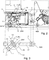
- Fig. 3:
- eine schematische Darstellung des in der
Figur 2 - Fig. 4:
- eine schematische Darstellung eines Ausschnitts der Gesamtvorrichtung mit einem sich anschließenden Formatabschnitt;
- Fig. 5:
- die Regelung der Zugkraft der inneren Lage.
- Fig. 1:
- a schematic representation of an overall device for transporting a strip or strip-shaped material;
- Fig. 2:
- an enlarged section of the overall device;
- Fig. 3:
- a schematic representation of the in the
Figure 2 shown section from above; - Fig. 4:
- a schematic representation of a section of the overall device with an adjoining format section;
- Fig. 5:
- the regulation of the tensile force of the inner layer.
In der
Der gesamte Papierlauf kann in einen ersten Papierlauf I und einen zweiten Papierlauf II unterteilt werden, wobei in dem ersten Papierlauf I die äußere Lage des Produktes, wie z.B. eine Zigarettenumhüllungslage, in Form eines doppeltbreiten Papierstreifens zugeführt wird, und in dem zweiten Papierlauf II die innere Lage des Produktes, wie z.B. eine Zigaretteninnenlage (Double Wrap), ebenfalls in Form eines doppeltbreiten Papierstreifens zugeführt wird. Die doppeltbreiten Papierstreifen werden in den Papierläufen I und II jeweils in zwei einfachbreite parallele Papierstreifen geschnitten und anschließend zu zwei parallel verlaufenden, doppelten Lagen aufeinandergelegt. Die doppeltlagigen Papierstreifen werden anschließend in einem Umlenkabschnitt in eine horizontale Ausrichtung umgelenkt und in einen Formatabschnitt der Herstellmaschine eingeführt. Vor dem Einführen der aufeinanderliegenden Lagen in den Formatabschnitt wird jeweils ein endloser Tabakstrang oder Filterstrang auf die übereinanderliegenden Lagen aufgelegt, welche in dem Formatabschnitt durch Umschlagen und Verkleben der Ränder der endlosen Papierstreifen zu jeweils einem formfesten endlosen Strang fixiert werden.The entire paper run can be divided into a first paper run I and a second paper run II, with the outer layer of the product, such as a cigarette wrapper, being fed in the form of a double-width paper strip in the first paper run I, and the inner one in the second paper run II Position of the product, such as a cigarette inner layer (double wrap), is also supplied in the form of a double-wide paper strip. The double-width paper strips are each cut into two single-width parallel paper strips in paper runs I and II and then placed on top of one another to form two parallel, double layers. The double-ply paper strips are then deflected into a horizontal orientation in a deflection section and introduced into a format section of the manufacturing machine. Before the superimposed layers are introduced into the format section, an endless rod of tobacco or filter rod is placed on the layers lying one above the other, which are fixed in the format section by folding over and gluing the edges of the endless paper strips to form a rigid endless rod.
Dem ersten Papierlauf I wird der doppeltbreite endlose Papierstreifen in einer später noch näher dargestellten winkligen Ausrichtung über eine Umlenkrolle M31S zugeführt. Vor der Umlenkrolle M31S ist ein optischer Sensor B10S vorgesehen, der eine Istlage der Kante des Papierstreifens sensiert, und daraufhin bei einer Überschreitung eines vorbestimmten Toleranzbereichs der Istlage von der Solllage ein entsprechendes Stellsignal an die regelbare Umlenkrolle M31S übermittelt. Die Umlenkrolle M31S selbst oder eine daran angeordnete Führung ist querverschieblich ausgebildet und führt bei einer entsprechenden Ansteuerung eine Querbewegung zur Korrektur der Papierkantenlage aus. Durch eine entsprechend schnelle Regelung und die Nähe des optischen Sensors B10S zu der Umlenkrolle M31S bzw. dem Papiereinlauf des ersten Papierlaufs I wird der Papierstreifen mit einer sehr hohen Lagegenauigkeit in den ersten Papierlauf I eingeführt. Nach dem Einlauf des Papierstreifens in den ersten Papierlauf I wird der Papierstreifen von einem ersten Zugwalzenpapier Z/W1 ergriffen und in einer später noch näher beschriebenen Vorrichtung in eine vorbestimmte Transportrichtung bzw. Transportebene umgelenkt. Dicht hinter dem ersten Zugwalzenpaar Z/W1 nach der ersten Umlenkung ist ein Ultraschallsensor B21S angeordnet, welcher nach einem Wechsel der Bobine die Rändelstelle erkennt und daraufhin die in einem vorbestimmten Zeitfenster hergestellten Produkte aus dem nachfolgenden Herstellungsprozess auswirft.The double-width, endless paper strip is fed to the first paper run I in an angular orientation, which will be shown in more detail later, via a deflection roller M31S. An optical sensor B10S is provided in front of the deflection roller M31S, which senses an actual position of the edge of the paper strip and then transmits a corresponding control signal to the controllable deflection roller M31S if the actual position exceeds a predetermined tolerance range. The deflection roller M31S itself or a guide arranged on it is designed to be transversely displaceable and, when activated accordingly, executes a transverse movement to correct the position of the paper edge. Due to a correspondingly fast regulation and the proximity of the optical sensor B10S to the deflecting roller M31S or the paper inlet of the first paper run I, the paper strip is introduced into the first paper run I with a very high positional accuracy. After the paper strip has entered the first paper run I, the paper strip is gripped by a first roll paper Z / W1 and deflected into a predetermined transport direction or transport plane in a device which will be described in more detail later. An ultrasonic sensor B21S is arranged right behind the first pair of draw rollers Z / W1 after the first deflection, which detects the knurling point after the reel has been changed and then ejects the products manufactured in a predetermined time window from the subsequent manufacturing process.
Nachdem der Papierstreifen in die Transportebene umgelenkt wurde, wird dieser über eine schwenkbar gelagerte Spannrolle M2S geführt, welche durch Ausführen einer Schwenkbewegung die Zugspannung in dem Papierstreifen erhöht oder senkt. Gleichzeitig umfasst die Spannrolle M2S eine Messeinrichtung mittels derer die Istzugkraft in dem Papierstreifen sensiert wird. Im Anschluss wird der doppeltbreite Papierstreifen durch eine Zug-Schneidwalzenkombination Z/S/W1 geführt, welche durch eine Umlenkrolle M9S angetrieben wird. In der Zug-Schneidwalzenkombination Z/S/W1 wird der doppeltbreite Papierstreifen von einer an der Umlenkrolle M9S anliegenden und durch diese angetriebenen Schneidwalze S/M1 in zwei einfachbreite Papierstreifen geschnitten. Nach dem Verlassen der Zug-Schneidwalzenkombination Z/S/W1 werden die zwei parallel aneinander anliegenden Papierstreifen, für den Fall, dass ein Druckwerk vorhanden ist, an diesem vorbeigeführt und anschließend durch eine Spreizeinrichtung 15 voneinander getrennt. Die Spreizeinrichtung 15 ist durch mehrere aufeinanderfolgend angeordnete Kegelrollen oder zylindrische, in einem Winkel zu der Querausrichtung des Papierstreifens angeordnete Rollen gebildet, welche durch ihre Kegelausrichtung bzw. Ausrichtung der Längsachen der winkligen Rollen die einzelnen Papierstreifen parallel versetzen. Die Kegelrollen bzw. die winkligen Rollen sind derart befestigt, dass der Mittenabstand zwischen wenigstens zwei der Rollen senkrecht oder parallel zu deren Längsachsen durch einen oder zwei Antriebe M25/26S verstellbar ist, wodurch der seitliche Versatz der aus der Spreizeinrichtung 15 austretenden einfachbreiten Papierstreifen veränderbar ist. In Verlaufsrichtung der Papierstreifen hinter der Spreizeinrichtung 15 ist ein Sensor B19S vorgesehen, welcher die Breiten der Papierstreifen sensiert und vergleicht. Für den Fall, dass die sensierte Differenz der Breiten eine vorgegebene Solldifferenz überschreitet, wird ein Signal an die regelbare Umlenkrolle M31S gegeben, welche den doppeltbreiten Papierstreifen vor dem Einlauf in den ersten Papierlauf I seitlich verschiebt, wodurch die relative Lage des Papierstreifens zu der Schneidwalze S/M1 und damit die Lage der Schnittkante des doppeltbreiten Papierstreifens verändert wird. Nach dem Sensor B19S ist ein weiterer, auf die Kanten der Papierstreifen gerichteter Ultraschallsensor B60S vorgesehen, dessen Funktion später noch näher erläutert wird.After the paper strip has been deflected into the transport plane, it is guided over a pivotably mounted tensioning roller M2S, which increases or decreases the tensile stress in the paper strip by executing a pivoting movement. At the same time, the tensioning roller M2S includes a measuring device by means of which the actual tensile force in the paper strip is sensed. The double-width paper strip is then fed through a pull-cutting roller combination Z / S / W1, which is driven by a pulley M9S. In the pull-cutting roller combination Z / S / W1, the double-width paper strip is cut into two single-width paper strips by a cutting roller S / M1 resting against the deflection roller M9S and driven by it. After leaving the pull-cutting roller combination Z / S / W1, the two parallel strips of paper, in the event that a printing unit is present, are on This is passed by and then separated from one another by a spreading
Der zweite Papierlauf II der inneren Lage (Double Wrap), nachfolgend ebenfalls als Papierstreifen bezeichnet, wird ebenfalls als doppeltbreiter Papierstreifen von einer nicht dargestellten Bobine abgewickelt und in der Transportrichtung bzw. der durch die Transportrichtungen aufgespannten Transportebene zugeführt. Vor dem Eintritt des Papierstreifens in den zweiten Papierlauf II gelangt der Papierstreifen an einer Umlenkrolle M32S zur Anlage und wird vorher an einem optischen Sensor B11S vorbeigeführt, welcher dieselbe Funktion hat wie der optische Sensor B10S in dem ersten Papierlauf I. Nach dem Eintritt des Papierstreifens in den zweiten Papierlauf II wird dieser an einem Ultraschallsensor B22S zur Erkennung der durch einen Wechsel der Bobine erzeugten Rändelstelle vorbeigeführt und anschließend einer Zug-Schneidwalzenkombination Z/S/W2 mit einer Antriebrolle M11S und einer Schneidwalze S/M2 zugeführt, welche dieselbe Funktion wie die Zug-Schneidwalzenkombination Z/S/W1 des ersten Papierlaufs I hat. Nach dem Austritt der nunmehr geschnittenen, einfachbreiten Papierstreifen, werden diese in einer Spreizeinrichtung 16 seitlich nach außen versetzt und anschließend in gleicher Weise wie die Papierstreifen des ersten Papierlaufs I an einem optischen Sensor B20S zur Sensierung der Breite der Papierstreifen und an einem Ultraschallsensor B61S zur Sensierung der Papierkantenlage vorbeigeführt. Der Sensor B20S sensiert die Breite der einfachbreiten Papierstreifen und steuert bei vorhandenen Abweichungen der Differenz der Breiten von einer vorgegebenen maximalen Solldifferenz die Umlenkrolle M32S an, welche den doppeltbreiten Papierstreifen vor dem Durchlaufen der Zug-Schneidwalzenkombination Z/S/W2 seitlich verschiebt. Die Ultraschallsensoren B60S und B61S sind jeweils auf die Papierkanten der einfachbreiten Papierstreifen gerichtet. Für den Fall, dass die Istlage der Papierkanten außerhalb eines vorgegebenen Toleranzbereichs liegt, werden die Antriebe M25/26S und/oder M27/28S angesteuert, wodurch der seitliche Versatz und damit die Papierkantenlage jedes einzelnen Papierstreifens oder der Papierstreifen paarweise verändert werden kann. Dies hat den Vorteil, dass durch die Regelung der Papierkantenlage auch die relative Lage der Papierkanten der übereinanderliegenden Lagen in dem Formatabschnitt zueinander gesteuert werden kann. Durch die dadurch verbesserte Ausrichtung der Papierkanten in dem Formatabschnitt wird die Leimspur mit einer erhöhten Genauigkeit auf einen dafür vorgesehenen Rand aufgetragen und das Umschlagen und Verkleben kann mit einer wesentlich höheren Genauigkeit vorgenommen werden.The second paper run II of the inner layer (double wrap), hereinafter also referred to as paper strip, is also unwound as a double-width paper strip from a reel, not shown, and fed in the transport direction or the transport plane spanned by the transport directions. Before the paper strip enters the second paper path II, the paper strip comes to rest on a deflection roller M32S and is previously guided past an optical sensor B11S, which has the same function as the optical sensor B10S in the first paper path I. After the paper strip enters the second paper run II, it is guided past an ultrasonic sensor B22S to detect the knurling created by changing the reel and then fed to a pull-cutting roller combination Z / S / W2 with a drive roller M11S and a cutting roller S / M2, which has the same function as the pull -Cutting roller combination Z / S / W1 of the first paper run I has. To the exit of the now cut, single-width paper strips, these are laterally offset outward in a spreading
Nach dem Eintritt des doppeltbreiten Papierstreifens in die Zug-Schneidwalzenkombination Z/S/W2 entspricht der zweite Papierlauf II dem ersten Papierlauf I, mit dem Unterschied, dass kein Druckwerk vorgesehen ist, wie dies bei dem ersten Papierlauf I der Fall sein kann. Ferner erfolgt die Papierzufuhr zu dem zweiten Papierlauf II nicht winklig, und es ist keine erste Zugwalze, Umlenkung und keine Spannrolle vor der Zug-Schneidkombination vorgesehen.After the double-width paper strip enters the pull-cutting roller combination Z / S / W2, the second paper path II corresponds to the first paper path I, with the difference that no printing mechanism is provided, as can be the case with the first paper path I. Furthermore, the paper is not fed to the second paper path II at an angle, and there is no first pull roller, deflection and no tensioning roller in front of the pull-cutting combination.
Ein besonders wichtiges Merkmal für eine genaue Führung der Papierstreifen und insbesondere für eine lagegenaue Anordnung der Papierstreifen übereinander, ist die Sensierung der Breite der Streifen mit den Sensoren B19S und B20S und eine Ansteuerung der Umlenkrollen M31S und M32S bei Abweichungen der Istbreiten von den Sollbreiten, da hierdurch die Einhaltung der Sollbreiten der Papierstreifen vor dem Aufeinanderlegen der Lagen geregelt wird und dadurch die Einhaltung der relativen Ausrichtung der Papierkanten zueinander, d.h. nach dem Übereinanderlegen der Lagen ebenfalls mitgeregelt wird. Da die Lage der Papierstreifen jeweils durch an den Eintrittsseiten der Papierläufe I und II angeordnete Aktuatoren gesteuert wird, werden die Papierstreifen bereits mit einer korrigierten Vorausrichtung in die Papierläufe I und II eingeführt, so dass sich die Papierstreifen nach dem Durchlaufen der Papierläufe I und II beim Passieren der Sensoren B19S und B20S im Idealfall wieder in der Solllage befinden.A particularly important feature for a precise guidance of the paper strips and in particular for a precise arrangement of the paper strips on top of each other is the sensing of the width of the strips with the sensors B19S and B20S and a control of the deflection rollers M31S and M32S in case of deviations of the actual widths from the nominal widths, there this regulates compliance with the nominal widths of the paper strips before the layers are laid one on top of the other, and compliance with the relative alignment of the paper edges to one another, ie after the layers have been laid on top of one another, is also controlled. Since the position of the paper strips is controlled by actuators arranged on the entry sides of the paper runs I and II, the paper strips are already fed into the paper runs I and II with a corrected pre-alignment so that the paper strips move after they have passed through the paper runs I and II If you pass the sensors B19S and B20S, you should ideally be in the target position again.
Die aus dem ersten und zweiten Papierlauf I und II austretenden Papierstreifen werden zu zwei parallellaufenden, doppellagigen Streifen übereinandergelegt und über eine Umlenkeinrichtung 7,18 auf ein Formatband 9 aufgelegt, wie auch in der
In der
In den
Nach dem Einlauf des Papierstreifens in die Vorrichtung wird dieser zunächst an dem ersten Zugwalzenpaar Z/W1 vorbeigeführt, welches eine auf den Papierstreifen wirkende Zugkrafterzeugt, durch die der Papierstreifen transportiert wird. Nach dem Verlassen des Zugwalzenpaares Z/W1 wird der Papierstreifen über zwei Umlenkungen 1 und 2 geführt, zwischen denen der auf den Papierstreifen gerichtete Sensor B21S angeordnet ist. Im weiteren Verlauf wird der Papierstreifen über einen feststehenden Umlenkbolzen f.U/B geführt, welcher mit seiner Längsachse L3 in Richtung der oder parallel zu der Winkelhalbierenden ausgerichtet ist, die zwischen den Längsachsen L1 und L2 des Papierstreifens in der Zuführung und nach dem Verlassen des Umlenkbolzens f.U/B verläuft. Die Ausrichtung des Papierstreifens nach dem Verlassen des Umlenkbolzens f.U/B in Richtung der Längsachse L2 entspricht dabei der Transportebene, in der der Papierstreifen anschließend durch mehrfache Umlenkungen in verschiedenen Transportrichtungen bis zu dem Formatband 9 transportiert wird. Der Papierstreifen einfacher Breite wird beim Schneiden in zwei einfachbreite Papierstreifen geteilt, welche nach dem Verlassen der Zug-Schneidwalzenkombination Z/S/W1 aus der Transportebene seitlich in zwei zu der Transportebene parallel versetzte Ebenen versetzt werden, so dass die ursprüngliche Transportebene zwischen den einfachbreiten Papierstreifen verläuft.After the paper strip has entered the device, it is first guided past the first pair of draw rollers Z / W1, which generate a tensile force acting on the paper strip, through which the paper strip is transported. After leaving the pair of draw rollers Z / W1, the paper strip is guided over two
In der
Nach der Umlenkung des Papierstreifens an dem feststehenden Umlenkbolzen f.U/B wird der Papierstreifen nochmals über zwei Umlenkungen 3 und 4 zu der Spannrolle M2S hin geführt, an der die Zugkraft in dem Papierstreifen für die vorgeschlagene Ansteuerung des Zugwalzenpaares Z/W1 gemessen wird.After the paper strip has been deflected on the fixed deflection bolt f.U / B, the paper strip is again guided via two
Der feststehende Umlenkbolzen f.U/B ist mit einer Verstelleinrichtung 13 versehen, mittels der der Winkel A2 bzw. C1 zur Feinjustierung geringfügig verstellt werden kann. Während des Durchlaufes des Papierstreifens ist der feststehende Umlenkbolzen f.U/B nach der Feinjustierung als feststehend anzusehen, d.h. der einmalig eingestellte Winkel A1 ist anschließend konstant. Dazu ist die Verstelleinrichtung 13 mit einer nicht näher dargestellten arretierbaren Feststelleinrichtung versehen.The fixed deflection bolt f.U / B is provided with an adjusting
Nach dem Umlenken des Papierstreifens in die Transportebene wird der Papierstreifen über die schwenkbar gelagerte Spannrolle M2S geführt, über die der Papierstreifen gespannt wird. Außerdem wird die in dem Papierstreifen wirkende Zugkraft mittels der Spannrolle M2S sensiert und in einer Steuerungseinrichtung mit einer vorgegebenen Zugkraft verglichen. Für den Fall, dass die sensierte Istzugkraft von der vorgegebenen Sollzugkraft abweicht, wird ein Steuersignal an das erste Zugwalzenpaar Z/W1 zur Verminderung oder Erhöhung der Zugkraft gegeben, so dass die Regeldifferenz der Zugkraft kompensiert wird. Der Vorteil dieser Lösung ist darin zu sehen, dass durch die Anordnung des feststehenden Umlenkbolzens f.U/B zwischen dem ersten Zugwalzenpaar Z/W1 und der Spannrolle M2S, die an dem feststehenden Umlenkbolzen f.U/B auf den Papierstreifen wirkenden Reibkräfte keinen Einfluss auf die während der weiteren Transportbewegung in dem Papierstreifen wirkende Zugkraft hat, da die Zugkraft in dem Papierstreifen vor dem feststehenden Umlenkbolzen f.U/B geregelt wird.After the paper strip has been deflected into the transport level, the paper strip is guided over the pivotably mounted tensioning roller M2S, which is used to tension the paper strip. In addition, the tensile force acting in the paper strip is sensed by means of the tensioning roller M2S and compared with a predetermined tensile force in a control device. In the event that the sensed actual tensile force deviates from the specified target tensile force, a control signal is sent to the first pair of draw rollers Z / W1 to reduce or increase the tensile force, so that the control difference in the tensile force is compensated. The advantage of this solution can be seen in the fact that, due to the arrangement of the fixed deflection bolt fU / B between the first pair of draw rollers Z / W1 and the tensioning roller M2S, the frictional forces acting on the fixed deflection bolt fU / B on the paper strip have no influence on the during the further transport movement in the paper strip has acting tensile force, since the tensile force in the paper strip is regulated in front of the fixed deflection pin fU / B.
Der Umlenkbolzen f.U/B ist während der Transportbewegung des Papierstreifens als feststehend anzusehen, er kann aber einmalig zur Feinjustierung und zur Verwirklichung von verschiedenen Zulaufrichtungen des Papierstreifens in einem geringen Winkelbereich mittels einer Verstelleinrichtung 13 verschwenkt werden. Ferner ist die gesamte Vorrichtung mit dem ersten Zugwalzenpaar Z/W1 und dem feststehenden Umlenkbolzen f.U/B auf einem gemeinsamen Gestell 14 angeordnet, welches bedarfsweise zur Verwirklichung von Zulaufrichtungen mit einem erheblich anderen Winkel in verschiedenen Ausrichtungen montiert werden kann, so dass Zulaufrichtungen des Papierstreifens in einem beliebigen Winkel verwirklicht werden können. An dem Umlenkbolzen f.U/B ist an der Ablaufseite des Papierstreifens eine Absaugvorrichtung 5 unterhalb des Papierstreifens angeordnet, mittels derer die sich an dem feststehenden Umlenkbolzen f.U/B lösenden Papierpartikel abgesaugt werden.The deflection bolt f.U / B is to be regarded as stationary during the transport movement of the paper strip, but it can be pivoted once for fine adjustment and to achieve different feed directions of the paper strip in a small angular range by means of an adjusting
Selbstverständlich kann an dem zweiten Papierlauf II auch eine Twistvorrichtung vorgesehen sein, sofern der Papierstreifen auch hier winklig zugeführt werden muss oder soll.Of course, a twist device can also be provided on the second paper run II if the paper strip must or should be fed at an angle here as well.
Sofern in der Ausführungsform Ultraschallsensoren, optische Sensoren oder dergleichen beschrieben worden sind, ist es naheliegend, diese bei einer vergleichbaren Messgenauigkeit auch gegen andersartige Sensoren auszutauschen.Insofar as ultrasonic sensors, optical sensors or the like have been described in the embodiment, it is obvious to exchange them for sensors of a different type with a comparable measurement accuracy.
Claims (4)
- Device for conveying band-shaped or strip-shaped material for an apparatus for producing rod-shaped products of the tobacco processing industry, which material is guided around a deflection means (7, 18) in two layers lying on top of each other, and is placed on a garniture tape further conveying the layers, wherein the layers are each supplied in different paper runs (I, II), characterized in that in the paper run (II) of the layer which does not get in direct contact with the garniture tape (9) a tensioning roller is provided on a force measuring system (12) arranged between the tensioning roller and the deflection means (7, 17).
- Device according to claim 1, characterized in that a mechanism (19) is provided, by which the layer which does not get in contact with the garniture tape can be loaded with additional pressure in the area of the deflection means (7, 18) .
- Device according to claim 2, characterized in that the mechanism (19) is a pneumatic mechanism.
- Device according to any one of the preceding claims, characterized in that the device is configured in such a way that the band-shaped or strip-shaped material can be fed from different first angles (A1) to a conveying plane of the band-shaped or strip-shaped material in the device, and that a mechanism for displacing the band-shaped or strip-shaped material transverse to its longitudinal axis (L1) is provided at the inlet side of the band-shaped or strip-shaped material, which displacing mechanism can be actuated depending on a position sensor (B19S) which is arranged after a splitting mechanism (15) along the pathway of the band-shaped or strip-shaped material.
Priority Applications (1)
| Application Number | Priority Date | Filing Date | Title |
|---|---|---|---|
| PL13196195T PL2716170T5 (en) | 2011-09-28 | 2012-09-14 | Device for transporting material in the form of strips or tape |
Applications Claiming Priority (2)
| Application Number | Priority Date | Filing Date | Title |
|---|---|---|---|
| DE102011114434A DE102011114434A1 (en) | 2011-09-28 | 2011-09-28 | Device for transporting strip or strip material |
| EP12184383.3A EP2574244B1 (en) | 2011-09-28 | 2012-09-14 | Device for transporting material in the form of strips or tape |
Related Parent Applications (2)
| Application Number | Title | Priority Date | Filing Date |
|---|---|---|---|
| EP12184383.3A Division EP2574244B1 (en) | 2011-09-28 | 2012-09-14 | Device for transporting material in the form of strips or tape |
| EP12184383.3A Division-Into EP2574244B1 (en) | 2011-09-28 | 2012-09-14 | Device for transporting material in the form of strips or tape |
Publications (3)
| Publication Number | Publication Date |
|---|---|
| EP2716170A1 EP2716170A1 (en) | 2014-04-09 |
| EP2716170B1 EP2716170B1 (en) | 2016-02-03 |
| EP2716170B2 true EP2716170B2 (en) | 2021-09-22 |
Family
ID=46963479
Family Applications (3)
| Application Number | Title | Priority Date | Filing Date |
|---|---|---|---|
| EP12184383.3A Revoked EP2574244B1 (en) | 2011-09-28 | 2012-09-14 | Device for transporting material in the form of strips or tape |
| EP13196193.0A Revoked EP2712508B1 (en) | 2011-09-28 | 2012-09-14 | Device for transporting material in the form of strips or tape |
| EP13196195.5A Active EP2716170B2 (en) | 2011-09-28 | 2012-09-14 | Device for transporting material in the form of strips or tape |
Family Applications Before (2)
| Application Number | Title | Priority Date | Filing Date |
|---|---|---|---|
| EP12184383.3A Revoked EP2574244B1 (en) | 2011-09-28 | 2012-09-14 | Device for transporting material in the form of strips or tape |
| EP13196193.0A Revoked EP2712508B1 (en) | 2011-09-28 | 2012-09-14 | Device for transporting material in the form of strips or tape |
Country Status (4)
| Country | Link |
|---|---|
| EP (3) | EP2574244B1 (en) |
| CN (1) | CN103030022B (en) |
| DE (1) | DE102011114434A1 (en) |
| PL (3) | PL2574244T3 (en) |
Families Citing this family (3)
| Publication number | Priority date | Publication date | Assignee | Title |
|---|---|---|---|---|
| WO2016049899A1 (en) * | 2014-09-30 | 2016-04-07 | 惠州市吉瑞科技有限公司 | Material delivering device |
| DE102018110762B4 (en) * | 2018-05-04 | 2019-11-21 | Hauni Maschinenbau Gmbh | Production of strands of the tobacco processing industry, in particular of hollow strands |
| CN113619296B (en) * | 2021-07-23 | 2023-01-13 | 天津七所精密机电技术有限公司 | High-precision stepping paper feeding motion system suitable for plotter and paper feeding control method |
Family Cites Families (20)
| Publication number | Priority date | Publication date | Assignee | Title |
|---|---|---|---|---|
| GB279608A (en) | 1926-09-29 | 1927-11-03 | Ernest Arthur Timson | Improvements in or relating to web-guiding devices for printing and other machines |
| GB468444A (en) | 1936-01-03 | 1937-07-05 | Charles Edward Taroni | Improvements in and relating to the manufacture of sponge cake and the like web material |
| GB582530A (en) | 1944-04-04 | 1946-11-20 | Dunlop Rubber Co | Improvements in or relating to conveyors for web material |
| GB879535A (en) | 1957-07-16 | 1961-10-11 | W H Smith & Son Alacra Ltd | Improvements in or relating to addressing machines |
| DE1186247B (en) | 1960-05-25 | 1965-01-28 | Philips Nv | Device for winding and unwinding a tape-shaped recording medium on or from a rotatable flange reel |
| GB957740A (en) | 1961-08-04 | 1964-05-13 | Horace Alexander Stone | A device for guiding continuously moving webs |
| GB1230257A (en) | 1968-07-19 | 1971-04-28 | ||
| GB1281478A (en) | 1969-10-17 | 1972-07-12 | Windmoeller & Hoelscher | Turning device for deflecting moving webs |
| IT1133242B (en) | 1980-02-27 | 1986-07-09 | Gd Spa | DEVIATOR FOR TAPES, PARTICULARLY PAPER TAPES |
| DE3401323A1 (en) * | 1983-02-01 | 1984-08-02 | Hauni-Werke Körber & Co KG, 2050 Hamburg | Method and apparatus for the simultaneous production of a plurality of wrapped fibre rods in the tobacco processing industry |
| USRE36154E (en) * | 1984-02-23 | 1999-03-23 | G.D. Societa Per Azioni | Device for supplying webs of wrapping material to a cigarette making machine of the two rod type |
| IT1186553B (en) | 1985-01-16 | 1987-12-04 | Gd Spa | TAPE PAPER FEEDING DEVICE IN A CIGARETTE PACKING MACHINE |
| IT1189914B (en) * | 1986-01-20 | 1988-02-10 | Gd Spa | TAPE PAPER FEEDING DEVICE IN A DOUBLE CIGARETTE CIGARETTE PACKING MACHINE |
| GB2189467A (en) | 1986-04-23 | 1987-10-28 | New Jersey Machine Inc | Label dispenser with articulated guide |
| DE3809125A1 (en) | 1988-03-18 | 1989-09-28 | Sengewald Kg Karl H | METHOD AND DEVICE FOR RAPPORTALLY CONNECTING FILM TUBES DIVIDED IN BAG SECTIONS |
| US5156169A (en) | 1990-11-06 | 1992-10-20 | R. J. Reynolds Tobacco Company | Apparatus for making cigarettes |
| GB9422998D0 (en) | 1994-11-15 | 1995-01-04 | Rothmans International Ltd | Method and apparatus for wrapping a rod of smoking material |
| IT1287614B1 (en) * | 1996-12-24 | 1998-08-06 | Gd Spa | METHOD FOR FEEDING WRAPPING MATERIALS IN PACKAGING MACHINES |
| DE10044577A1 (en) * | 2000-09-08 | 2002-03-21 | Hauni Maschinenbau Ag | Method and device for separating a double-width starting wrapping material web into two partial webs |
| BR0316410B1 (en) * | 2002-11-19 | 2012-12-25 | apparatus for forming a cigarette with a plurality of narrow inner wrapping strips. |
-
2011
- 2011-09-28 DE DE102011114434A patent/DE102011114434A1/en active Pending
-
2012
- 2012-09-14 EP EP12184383.3A patent/EP2574244B1/en not_active Revoked
- 2012-09-14 PL PL12184383T patent/PL2574244T3/en unknown
- 2012-09-14 PL PL13196195T patent/PL2716170T5/en unknown
- 2012-09-14 EP EP13196193.0A patent/EP2712508B1/en not_active Revoked
- 2012-09-14 PL PL13196193T patent/PL2712508T3/en unknown
- 2012-09-14 EP EP13196195.5A patent/EP2716170B2/en active Active
- 2012-09-27 CN CN201210368912.5A patent/CN103030022B/en active Active
Also Published As
| Publication number | Publication date |
|---|---|
| PL2716170T5 (en) | 2021-12-27 |
| EP2712508A1 (en) | 2014-04-02 |
| DE102011114434A1 (en) | 2013-03-28 |
| EP2716170A1 (en) | 2014-04-09 |
| PL2712508T3 (en) | 2016-07-29 |
| CN103030022B (en) | 2017-04-26 |
| EP2574244B1 (en) | 2016-02-03 |
| PL2716170T3 (en) | 2016-07-29 |
| PL2574244T3 (en) | 2016-08-31 |
| EP2716170B1 (en) | 2016-02-03 |
| EP2712508B1 (en) | 2016-02-03 |
| EP2574244A3 (en) | 2013-06-19 |
| EP2574244A2 (en) | 2013-04-03 |
| CN103030022A (en) | 2013-04-10 |
Similar Documents
| Publication | Publication Date | Title |
|---|---|---|
| EP1790601B1 (en) | Control of the web tension of a running web | |
| DE4436667A1 (en) | Packing method and device | |
| DE19641509A1 (en) | Method for transporting a belt assembly strip for assembling a belt for a pneumatic vehicle tire | |
| EP1314668B1 (en) | Apparatus for transporting web material | |
| EP2716170B2 (en) | Device for transporting material in the form of strips or tape | |
| EP2268481B1 (en) | Device and method for producing bags | |
| EP2132117B1 (en) | Method and control circuit for the adjustment of a gap | |
| EP2255681B1 (en) | String machine for the tobacco processing industry | |
| DE102018110762B4 (en) | Production of strands of the tobacco processing industry, in particular of hollow strands | |
| EP3694799A1 (en) | Sheet orientation device, machine for processing a sheet, and method for orienting a sheet | |
| DE102014104662B4 (en) | Working method for multi-color digital multicolor printing | |
| DE19850901A1 (en) | Sheet transport device for paper processing machine regulates force applied for overlapping sheets dependent on transport device, sheet and environmental parameters | |
| EP1661833A1 (en) | Method and device for treating printed products | |
| EP2074895A1 (en) | Lining device in a machine for the tobacco processing industry | |
| EP3737630B1 (en) | Apparatus for cutting a material web into individual sheets having a web store | |
| EP3061716A1 (en) | Method for the production of newspaper product | |
| DE3744107C2 (en) | ||
| EP1522513A2 (en) | Device for separating flat products arranged in shingled formation | |
| EP1897454A1 (en) | V-shaped assembly of suction apertures | |
| EP3118147B1 (en) | Buckling folder and sheet folding machine with such a buckling folder | |
| EP3142952B1 (en) | Device and method for adjusting the position of a packaging material web with respect to a reference in a packaging machine | |
| DE202013104653U1 (en) | Slitter for cutting a cord band | |
| EP3336228B1 (en) | Method for operating a draw frame and a draw frame for drawing a sliver | |
| WO2024002720A1 (en) | Machine in the tobacco processing industry for producing a rod, and method for producing a rod in the tobacco processing industry | |
| DE102017005786A1 (en) | Transport device for a wrapping strip for products of the tobacco processing industry and method for controlling such a transport device |
Legal Events
| Date | Code | Title | Description |
|---|---|---|---|
| PUAI | Public reference made under article 153(3) epc to a published international application that has entered the european phase |
Free format text: ORIGINAL CODE: 0009012 |
|
| AC | Divisional application: reference to earlier application |
Ref document number: 2574244 Country of ref document: EP Kind code of ref document: P |
|
| AK | Designated contracting states |
Kind code of ref document: A1 Designated state(s): AL AT BE BG CH CY CZ DE DK EE ES FI FR GB GR HR HU IE IS IT LI LT LU LV MC MK MT NL NO PL PT RO RS SE SI SK SM TR |
|
| AX | Request for extension of the european patent |
Extension state: BA ME |
|
| TPAC | Observations filed by third parties |
Free format text: ORIGINAL CODE: EPIDOSNTIPA |
|
| 17P | Request for examination filed |
Effective date: 20140919 |
|
| RBV | Designated contracting states (corrected) |
Designated state(s): AL AT BE BG CH CY CZ DE DK EE ES FI FR GB GR HR HU IE IS IT LI LT LU LV MC MK MT NL NO PL PT RO RS SE SI SK SM TR |
|
| GRAP | Despatch of communication of intention to grant a patent |
Free format text: ORIGINAL CODE: EPIDOSNIGR1 |
|
| RIC1 | Information provided on ipc code assigned before grant |
Ipc: A24C 5/20 20060101AFI20150420BHEP |
|
| INTG | Intention to grant announced |
Effective date: 20150508 |
|
| GRAS | Grant fee paid |
Free format text: ORIGINAL CODE: EPIDOSNIGR3 |
|
| GRAA | (expected) grant |
Free format text: ORIGINAL CODE: 0009210 |
|
| STAA | Information on the status of an ep patent application or granted ep patent |
Free format text: STATUS: THE PATENT HAS BEEN GRANTED |
|
| AC | Divisional application: reference to earlier application |
Ref document number: 2574244 Country of ref document: EP Kind code of ref document: P |
|
| AK | Designated contracting states |
Kind code of ref document: B1 Designated state(s): AL AT BE BG CH CY CZ DE DK EE ES FI FR GB GR HR HU IE IS IT LI LT LU LV MC MK MT NL NO PL PT RO RS SE SI SK SM TR |
|
| REG | Reference to a national code |
Ref country code: GB Ref legal event code: FG4D Free format text: NOT ENGLISH |
|
| REG | Reference to a national code |
Ref country code: AT Ref legal event code: REF Ref document number: 773232 Country of ref document: AT Kind code of ref document: T Effective date: 20160215 Ref country code: CH Ref legal event code: EP |
|
| REG | Reference to a national code |
Ref country code: IE Ref legal event code: FG4D Free format text: LANGUAGE OF EP DOCUMENT: GERMAN |
|
| REG | Reference to a national code |
Ref country code: DE Ref legal event code: R096 Ref document number: 502012005949 Country of ref document: DE |
|
| REG | Reference to a national code |
Ref country code: NL Ref legal event code: FP |
|
| REG | Reference to a national code |
Ref country code: LT Ref legal event code: MG4D |
|
| RAP2 | Party data changed (patent owner data changed or rights of a patent transferred) |
Owner name: HAUNI MASCHINENBAU GMBH |
|
| REG | Reference to a national code |
Ref country code: DE Ref legal event code: R081 Ref document number: 502012005949 Country of ref document: DE Owner name: HAUNI MASCHINENBAU GMBH, DE Free format text: FORMER OWNER: HAUNI MASCHINENBAU AG, 21033 HAMBURG, DE |
|
| PG25 | Lapsed in a contracting state [announced via postgrant information from national office to epo] |
Ref country code: NO Free format text: LAPSE BECAUSE OF FAILURE TO SUBMIT A TRANSLATION OF THE DESCRIPTION OR TO PAY THE FEE WITHIN THE PRESCRIBED TIME-LIMIT Effective date: 20160503 Ref country code: FI Free format text: LAPSE BECAUSE OF FAILURE TO SUBMIT A TRANSLATION OF THE DESCRIPTION OR TO PAY THE FEE WITHIN THE PRESCRIBED TIME-LIMIT Effective date: 20160203 Ref country code: ES Free format text: LAPSE BECAUSE OF FAILURE TO SUBMIT A TRANSLATION OF THE DESCRIPTION OR TO PAY THE FEE WITHIN THE PRESCRIBED TIME-LIMIT Effective date: 20160203 Ref country code: HR Free format text: LAPSE BECAUSE OF FAILURE TO SUBMIT A TRANSLATION OF THE DESCRIPTION OR TO PAY THE FEE WITHIN THE PRESCRIBED TIME-LIMIT Effective date: 20160203 Ref country code: GR Free format text: LAPSE BECAUSE OF FAILURE TO SUBMIT A TRANSLATION OF THE DESCRIPTION OR TO PAY THE FEE WITHIN THE PRESCRIBED TIME-LIMIT Effective date: 20160504 |
|
| PG25 | Lapsed in a contracting state [announced via postgrant information from national office to epo] |
Ref country code: PT Free format text: LAPSE BECAUSE OF FAILURE TO SUBMIT A TRANSLATION OF THE DESCRIPTION OR TO PAY THE FEE WITHIN THE PRESCRIBED TIME-LIMIT Effective date: 20160603 Ref country code: SE Free format text: LAPSE BECAUSE OF FAILURE TO SUBMIT A TRANSLATION OF THE DESCRIPTION OR TO PAY THE FEE WITHIN THE PRESCRIBED TIME-LIMIT Effective date: 20160203 Ref country code: LT Free format text: LAPSE BECAUSE OF FAILURE TO SUBMIT A TRANSLATION OF THE DESCRIPTION OR TO PAY THE FEE WITHIN THE PRESCRIBED TIME-LIMIT Effective date: 20160203 Ref country code: LV Free format text: LAPSE BECAUSE OF FAILURE TO SUBMIT A TRANSLATION OF THE DESCRIPTION OR TO PAY THE FEE WITHIN THE PRESCRIBED TIME-LIMIT Effective date: 20160203 Ref country code: RS Free format text: LAPSE BECAUSE OF FAILURE TO SUBMIT A TRANSLATION OF THE DESCRIPTION OR TO PAY THE FEE WITHIN THE PRESCRIBED TIME-LIMIT Effective date: 20160203 Ref country code: IS Free format text: LAPSE BECAUSE OF FAILURE TO SUBMIT A TRANSLATION OF THE DESCRIPTION OR TO PAY THE FEE WITHIN THE PRESCRIBED TIME-LIMIT Effective date: 20160603 |
|
| REG | Reference to a national code |
Ref country code: NL Ref legal event code: PD Owner name: HAUNI MASCHINENBAU GMBH; DE Free format text: DETAILS ASSIGNMENT: VERANDERING VAN EIGENAAR(S), VERANDERING VAN DE JURIDISCHE ENTITEIT; FORMER OWNER NAME: HAUNI MASCHINENBAU AG Effective date: 20160704 |
|
| PG25 | Lapsed in a contracting state [announced via postgrant information from national office to epo] |
Ref country code: EE Free format text: LAPSE BECAUSE OF FAILURE TO SUBMIT A TRANSLATION OF THE DESCRIPTION OR TO PAY THE FEE WITHIN THE PRESCRIBED TIME-LIMIT Effective date: 20160203 Ref country code: DK Free format text: LAPSE BECAUSE OF FAILURE TO SUBMIT A TRANSLATION OF THE DESCRIPTION OR TO PAY THE FEE WITHIN THE PRESCRIBED TIME-LIMIT Effective date: 20160203 |
|
| REG | Reference to a national code |
Ref country code: DE Ref legal event code: R026 Ref document number: 502012005949 Country of ref document: DE |
|
| PLBI | Opposition filed |
Free format text: ORIGINAL CODE: 0009260 |
|
| PG25 | Lapsed in a contracting state [announced via postgrant information from national office to epo] |
Ref country code: CZ Free format text: LAPSE BECAUSE OF FAILURE TO SUBMIT A TRANSLATION OF THE DESCRIPTION OR TO PAY THE FEE WITHIN THE PRESCRIBED TIME-LIMIT Effective date: 20160203 Ref country code: SM Free format text: LAPSE BECAUSE OF FAILURE TO SUBMIT A TRANSLATION OF THE DESCRIPTION OR TO PAY THE FEE WITHIN THE PRESCRIBED TIME-LIMIT Effective date: 20160203 Ref country code: SK Free format text: LAPSE BECAUSE OF FAILURE TO SUBMIT A TRANSLATION OF THE DESCRIPTION OR TO PAY THE FEE WITHIN THE PRESCRIBED TIME-LIMIT Effective date: 20160203 Ref country code: RO Free format text: LAPSE BECAUSE OF FAILURE TO SUBMIT A TRANSLATION OF THE DESCRIPTION OR TO PAY THE FEE WITHIN THE PRESCRIBED TIME-LIMIT Effective date: 20160203 |
|
| 26 | Opposition filed |
Opponent name: G.D S.P.A. Effective date: 20161103 |
|
| PLAX | Notice of opposition and request to file observation + time limit sent |
Free format text: ORIGINAL CODE: EPIDOSNOBS2 |
|
| PG25 | Lapsed in a contracting state [announced via postgrant information from national office to epo] |
Ref country code: SI Free format text: LAPSE BECAUSE OF FAILURE TO SUBMIT A TRANSLATION OF THE DESCRIPTION OR TO PAY THE FEE WITHIN THE PRESCRIBED TIME-LIMIT Effective date: 20160203 Ref country code: BG Free format text: LAPSE BECAUSE OF FAILURE TO SUBMIT A TRANSLATION OF THE DESCRIPTION OR TO PAY THE FEE WITHIN THE PRESCRIBED TIME-LIMIT Effective date: 20160503 Ref country code: BE Free format text: LAPSE BECAUSE OF NON-PAYMENT OF DUE FEES Effective date: 20160930 |
|
| PLBB | Reply of patent proprietor to notice(s) of opposition received |
Free format text: ORIGINAL CODE: EPIDOSNOBS3 |
|
| PG25 | Lapsed in a contracting state [announced via postgrant information from national office to epo] |
Ref country code: MC Free format text: LAPSE BECAUSE OF FAILURE TO SUBMIT A TRANSLATION OF THE DESCRIPTION OR TO PAY THE FEE WITHIN THE PRESCRIBED TIME-LIMIT Effective date: 20160203 |
|
| REG | Reference to a national code |
Ref country code: CH Ref legal event code: PL |
|
| GBPC | Gb: european patent ceased through non-payment of renewal fee |
Effective date: 20160914 |
|
| REG | Reference to a national code |
Ref country code: IE Ref legal event code: MM4A |
|
| REG | Reference to a national code |
Ref country code: FR Ref legal event code: ST Effective date: 20170531 |
|
| PG25 | Lapsed in a contracting state [announced via postgrant information from national office to epo] |
Ref country code: FR Free format text: LAPSE BECAUSE OF NON-PAYMENT OF DUE FEES Effective date: 20160930 Ref country code: IE Free format text: LAPSE BECAUSE OF NON-PAYMENT OF DUE FEES Effective date: 20160914 Ref country code: GB Free format text: LAPSE BECAUSE OF NON-PAYMENT OF DUE FEES Effective date: 20160914 Ref country code: CH Free format text: LAPSE BECAUSE OF NON-PAYMENT OF DUE FEES Effective date: 20160930 Ref country code: LI Free format text: LAPSE BECAUSE OF NON-PAYMENT OF DUE FEES Effective date: 20160930 |
|
| PG25 | Lapsed in a contracting state [announced via postgrant information from national office to epo] |
Ref country code: LU Free format text: LAPSE BECAUSE OF NON-PAYMENT OF DUE FEES Effective date: 20160914 |
|
| REG | Reference to a national code |
Ref country code: BE Ref legal event code: MM Effective date: 20160930 |
|
| PG25 | Lapsed in a contracting state [announced via postgrant information from national office to epo] |
Ref country code: CY Free format text: LAPSE BECAUSE OF FAILURE TO SUBMIT A TRANSLATION OF THE DESCRIPTION OR TO PAY THE FEE WITHIN THE PRESCRIBED TIME-LIMIT Effective date: 20160203 Ref country code: HU Free format text: LAPSE BECAUSE OF FAILURE TO SUBMIT A TRANSLATION OF THE DESCRIPTION OR TO PAY THE FEE WITHIN THE PRESCRIBED TIME-LIMIT; INVALID AB INITIO Effective date: 20120914 |
|
| PG25 | Lapsed in a contracting state [announced via postgrant information from national office to epo] |
Ref country code: MT Free format text: LAPSE BECAUSE OF FAILURE TO SUBMIT A TRANSLATION OF THE DESCRIPTION OR TO PAY THE FEE WITHIN THE PRESCRIBED TIME-LIMIT Effective date: 20160203 Ref country code: MK Free format text: LAPSE BECAUSE OF FAILURE TO SUBMIT A TRANSLATION OF THE DESCRIPTION OR TO PAY THE FEE WITHIN THE PRESCRIBED TIME-LIMIT Effective date: 20160203 |
|
| APBM | Appeal reference recorded |
Free format text: ORIGINAL CODE: EPIDOSNREFNO |
|
| APBP | Date of receipt of notice of appeal recorded |
Free format text: ORIGINAL CODE: EPIDOSNNOA2O |
|
| APAH | Appeal reference modified |
Free format text: ORIGINAL CODE: EPIDOSCREFNO |
|
| APBQ | Date of receipt of statement of grounds of appeal recorded |
Free format text: ORIGINAL CODE: EPIDOSNNOA3O |
|
| PG25 | Lapsed in a contracting state [announced via postgrant information from national office to epo] |
Ref country code: AL Free format text: LAPSE BECAUSE OF FAILURE TO SUBMIT A TRANSLATION OF THE DESCRIPTION OR TO PAY THE FEE WITHIN THE PRESCRIBED TIME-LIMIT Effective date: 20160203 Ref country code: TR Free format text: LAPSE BECAUSE OF FAILURE TO SUBMIT A TRANSLATION OF THE DESCRIPTION OR TO PAY THE FEE WITHIN THE PRESCRIBED TIME-LIMIT Effective date: 20160203 |
|
| REG | Reference to a national code |
Ref country code: AT Ref legal event code: MM01 Ref document number: 773232 Country of ref document: AT Kind code of ref document: T Effective date: 20170914 |
|
| PG25 | Lapsed in a contracting state [announced via postgrant information from national office to epo] |
Ref country code: AT Free format text: LAPSE BECAUSE OF NON-PAYMENT OF DUE FEES Effective date: 20170914 |
|
| APAH | Appeal reference modified |
Free format text: ORIGINAL CODE: EPIDOSCREFNO |
|
| APBU | Appeal procedure closed |
Free format text: ORIGINAL CODE: EPIDOSNNOA9O |
|
| PUAH | Patent maintained in amended form |
Free format text: ORIGINAL CODE: 0009272 |
|
| STAA | Information on the status of an ep patent application or granted ep patent |
Free format text: STATUS: PATENT MAINTAINED AS AMENDED |
|
| 27A | Patent maintained in amended form |
Effective date: 20210922 |
|
| AK | Designated contracting states |
Kind code of ref document: B2 Designated state(s): AL AT BE BG CH CY CZ DE DK EE ES FI FR GB GR HR HU IE IS IT LI LT LU LV MC MK MT NL NO PL PT RO RS SE SI SK SM TR |
|
| REG | Reference to a national code |
Ref country code: DE Ref legal event code: R102 Ref document number: 502012005949 Country of ref document: DE |
|
| REG | Reference to a national code |
Ref country code: NL Ref legal event code: FP |
|
| REG | Reference to a national code |
Ref country code: DE Ref legal event code: R081 Ref document number: 502012005949 Country of ref document: DE Owner name: KOERBER TECHNOLOGIES GMBH, DE Free format text: FORMER OWNER: HAUNI MASCHINENBAU GMBH, 21033 HAMBURG, DE |
|
| REG | Reference to a national code |
Ref country code: NL Ref legal event code: HC Owner name: KOERBER TECHNOLOGIES GMBH; DE Free format text: DETAILS ASSIGNMENT: CHANGE OF OWNER(S), CHANGE OF OWNER(S) NAME; FORMER OWNER NAME: HAUNI MASCHINENBAU GMBH Effective date: 20221031 |
|
| P01 | Opt-out of the competence of the unified patent court (upc) registered |
Effective date: 20230621 |
|
| PGFP | Annual fee paid to national office [announced via postgrant information from national office to epo] |
Ref country code: NL Payment date: 20230921 Year of fee payment: 12 |
|
| PGFP | Annual fee paid to national office [announced via postgrant information from national office to epo] |
Ref country code: PL Payment date: 20230828 Year of fee payment: 12 Ref country code: DE Payment date: 20230928 Year of fee payment: 12 |
|
| PGFP | Annual fee paid to national office [announced via postgrant information from national office to epo] |
Ref country code: IT Payment date: 20230927 Year of fee payment: 12 |