EP2711571A2 - Roulement avec poches de lubrifiant dans le chemin de roulement - Google Patents
Roulement avec poches de lubrifiant dans le chemin de roulement Download PDFInfo
- Publication number
- EP2711571A2 EP2711571A2 EP13184556.2A EP13184556A EP2711571A2 EP 2711571 A2 EP2711571 A2 EP 2711571A2 EP 13184556 A EP13184556 A EP 13184556A EP 2711571 A2 EP2711571 A2 EP 2711571A2
- Authority
- EP
- European Patent Office
- Prior art keywords
- contact area
- inner ring
- arc groove
- raceway surface
- ring raceway
- Prior art date
- Legal status (The legal status is an assumption and is not a legal conclusion. Google has not performed a legal analysis and makes no representation as to the accuracy of the status listed.)
- Withdrawn
Links
Images


Classifications
-
- F—MECHANICAL ENGINEERING; LIGHTING; HEATING; WEAPONS; BLASTING
- F16—ENGINEERING ELEMENTS AND UNITS; GENERAL MEASURES FOR PRODUCING AND MAINTAINING EFFECTIVE FUNCTIONING OF MACHINES OR INSTALLATIONS; THERMAL INSULATION IN GENERAL
- F16C—SHAFTS; FLEXIBLE SHAFTS; ELEMENTS OR CRANKSHAFT MECHANISMS; ROTARY BODIES OTHER THAN GEARING ELEMENTS; BEARINGS
- F16C33/00—Parts of bearings; Special methods for making bearings or parts thereof
- F16C33/30—Parts of ball or roller bearings
- F16C33/66—Special parts or details in view of lubrication
- F16C33/6603—Special parts or details in view of lubrication with grease as lubricant
- F16C33/6607—Retaining the grease in or near the bearing
- F16C33/6614—Retaining the grease in or near the bearing in recesses or cavities provided in retainers, races or rolling elements
-
- F—MECHANICAL ENGINEERING; LIGHTING; HEATING; WEAPONS; BLASTING
- F16—ENGINEERING ELEMENTS AND UNITS; GENERAL MEASURES FOR PRODUCING AND MAINTAINING EFFECTIVE FUNCTIONING OF MACHINES OR INSTALLATIONS; THERMAL INSULATION IN GENERAL
- F16C—SHAFTS; FLEXIBLE SHAFTS; ELEMENTS OR CRANKSHAFT MECHANISMS; ROTARY BODIES OTHER THAN GEARING ELEMENTS; BEARINGS
- F16C33/00—Parts of bearings; Special methods for making bearings or parts thereof
- F16C33/30—Parts of ball or roller bearings
- F16C33/58—Raceways; Race rings
- F16C33/583—Details of specific parts of races
- F16C33/585—Details of specific parts of races of raceways, e.g. ribs to guide the rollers
-
- F—MECHANICAL ENGINEERING; LIGHTING; HEATING; WEAPONS; BLASTING
- F16—ENGINEERING ELEMENTS AND UNITS; GENERAL MEASURES FOR PRODUCING AND MAINTAINING EFFECTIVE FUNCTIONING OF MACHINES OR INSTALLATIONS; THERMAL INSULATION IN GENERAL
- F16C—SHAFTS; FLEXIBLE SHAFTS; ELEMENTS OR CRANKSHAFT MECHANISMS; ROTARY BODIES OTHER THAN GEARING ELEMENTS; BEARINGS
- F16C33/00—Parts of bearings; Special methods for making bearings or parts thereof
- F16C33/30—Parts of ball or roller bearings
- F16C33/66—Special parts or details in view of lubrication
- F16C33/6637—Special parts or details in view of lubrication with liquid lubricant
- F16C33/664—Retaining the liquid in or near the bearing
- F16C33/6648—Retaining the liquid in or near the bearing in a porous or resinous body, e.g. a cage impregnated with the liquid
-
- F—MECHANICAL ENGINEERING; LIGHTING; HEATING; WEAPONS; BLASTING
- F16—ENGINEERING ELEMENTS AND UNITS; GENERAL MEASURES FOR PRODUCING AND MAINTAINING EFFECTIVE FUNCTIONING OF MACHINES OR INSTALLATIONS; THERMAL INSULATION IN GENERAL
- F16C—SHAFTS; FLEXIBLE SHAFTS; ELEMENTS OR CRANKSHAFT MECHANISMS; ROTARY BODIES OTHER THAN GEARING ELEMENTS; BEARINGS
- F16C33/00—Parts of bearings; Special methods for making bearings or parts thereof
- F16C33/30—Parts of ball or roller bearings
- F16C33/66—Special parts or details in view of lubrication
- F16C33/6637—Special parts or details in view of lubrication with liquid lubricant
- F16C33/664—Retaining the liquid in or near the bearing
- F16C33/6651—Retaining the liquid in or near the bearing in recesses or cavities provided in retainers, races or rolling elements
-
- F—MECHANICAL ENGINEERING; LIGHTING; HEATING; WEAPONS; BLASTING
- F16—ENGINEERING ELEMENTS AND UNITS; GENERAL MEASURES FOR PRODUCING AND MAINTAINING EFFECTIVE FUNCTIONING OF MACHINES OR INSTALLATIONS; THERMAL INSULATION IN GENERAL
- F16C—SHAFTS; FLEXIBLE SHAFTS; ELEMENTS OR CRANKSHAFT MECHANISMS; ROTARY BODIES OTHER THAN GEARING ELEMENTS; BEARINGS
- F16C33/00—Parts of bearings; Special methods for making bearings or parts thereof
- F16C33/30—Parts of ball or roller bearings
- F16C33/66—Special parts or details in view of lubrication
- F16C33/6696—Special parts or details in view of lubrication with solids as lubricant, e.g. dry coatings, powder
-
- F—MECHANICAL ENGINEERING; LIGHTING; HEATING; WEAPONS; BLASTING
- F16—ENGINEERING ELEMENTS AND UNITS; GENERAL MEASURES FOR PRODUCING AND MAINTAINING EFFECTIVE FUNCTIONING OF MACHINES OR INSTALLATIONS; THERMAL INSULATION IN GENERAL
- F16C—SHAFTS; FLEXIBLE SHAFTS; ELEMENTS OR CRANKSHAFT MECHANISMS; ROTARY BODIES OTHER THAN GEARING ELEMENTS; BEARINGS
- F16C19/00—Bearings with rolling contact, for exclusively rotary movement
- F16C19/02—Bearings with rolling contact, for exclusively rotary movement with bearing balls essentially of the same size in one or more circular rows
- F16C19/04—Bearings with rolling contact, for exclusively rotary movement with bearing balls essentially of the same size in one or more circular rows for radial load mainly
- F16C19/06—Bearings with rolling contact, for exclusively rotary movement with bearing balls essentially of the same size in one or more circular rows for radial load mainly with a single row or balls
-
- F—MECHANICAL ENGINEERING; LIGHTING; HEATING; WEAPONS; BLASTING
- F16—ENGINEERING ELEMENTS AND UNITS; GENERAL MEASURES FOR PRODUCING AND MAINTAINING EFFECTIVE FUNCTIONING OF MACHINES OR INSTALLATIONS; THERMAL INSULATION IN GENERAL
- F16C—SHAFTS; FLEXIBLE SHAFTS; ELEMENTS OR CRANKSHAFT MECHANISMS; ROTARY BODIES OTHER THAN GEARING ELEMENTS; BEARINGS
- F16C2300/00—Application independent of particular apparatuses
- F16C2300/02—General use or purpose, i.e. no use, purpose, special adaptation or modification indicated or a wide variety of uses mentioned
-
- F—MECHANICAL ENGINEERING; LIGHTING; HEATING; WEAPONS; BLASTING
- F16—ENGINEERING ELEMENTS AND UNITS; GENERAL MEASURES FOR PRODUCING AND MAINTAINING EFFECTIVE FUNCTIONING OF MACHINES OR INSTALLATIONS; THERMAL INSULATION IN GENERAL
- F16C—SHAFTS; FLEXIBLE SHAFTS; ELEMENTS OR CRANKSHAFT MECHANISMS; ROTARY BODIES OTHER THAN GEARING ELEMENTS; BEARINGS
- F16C33/00—Parts of bearings; Special methods for making bearings or parts thereof
- F16C33/30—Parts of ball or roller bearings
- F16C33/66—Special parts or details in view of lubrication
- F16C33/6637—Special parts or details in view of lubrication with liquid lubricant
- F16C33/6681—Details of distribution or circulation inside the bearing, e.g. grooves on the cage or passages in the rolling elements
-
- F—MECHANICAL ENGINEERING; LIGHTING; HEATING; WEAPONS; BLASTING
- F16—ENGINEERING ELEMENTS AND UNITS; GENERAL MEASURES FOR PRODUCING AND MAINTAINING EFFECTIVE FUNCTIONING OF MACHINES OR INSTALLATIONS; THERMAL INSULATION IN GENERAL
- F16C—SHAFTS; FLEXIBLE SHAFTS; ELEMENTS OR CRANKSHAFT MECHANISMS; ROTARY BODIES OTHER THAN GEARING ELEMENTS; BEARINGS
- F16C43/00—Assembling bearings
- F16C43/04—Assembling rolling-contact bearings
- F16C43/06—Placing rolling bodies in cages or bearings
Definitions
- the invention relates to a rolling bearing.
- a lubricant mainly, lubricating oil
- stirring resistance of the lubricant during the rotation of the bearing increases, and thus it becomes difficult to achieve lower torque. Further, if the amount of the supplied lubricant is insufficient, seizure may occur.
- a rolling bearing an angular contact ball bearing described in Japanese Utility Model Application Publication No. 5-8045 ( JP 5-8045 U ) is known.
- a recess portion one side of which reaches a raceway shoulder portion, is formed by recessing a portion with which a ball does not come into contact, in a raceway surface of an inner ring or an outer ring, over the entire circumference. (refer to JP 5-8045 U , for example).
- An object of the present invention is to provide a rolling bearing in which lubricating ability is able to be maintained over a long period of time by increasing lubricant retention ability.
- a rolling bearing including an inner ring; an outer ring disposed around an outer periphery of the inner ring with an annular space between the outer ring and the inner ring in a manner such that the outer ring and the inner ring are disposed on a same center line; and a plurality of rolling elements rollably disposed between an inner ring raceway surface formed on an outer peripheral surface of the inner ring and an outer ring raceway surface formed on an inner peripheral surface of the outer ring, wherein each of the inner ring raceway surface and the outer ring raceway surface has a contact area that comes into contact with the rolling elements, and a non-contact area that is formed adjacent to an outer side of an end portion of the contact area and does not come into contact with the rolling elements, and at the non-contact area of at least one of the inner ring raceway surface and the outer ring raceway surface, a lubricant retaining portion that retains a lubricant is formed by a recessed portion and a large
- the deep groove ball bearing as the rolling bearing includes an inner ring 10, an outer ring 20, a plurality of balls 31 as rolling elements, and a cage 35.
- the inner ring 10 is formed in a cylindrical shape and an inner ring raceway surface 12 forming an arc-shaped annular groove is formed at an axial central portion of an outer peripheral surface 11 of the inner ring 10.
- the outer ring 20 is formed in a cylindrical shape having an inside diameter larger than an outside diameter of the inner ring 10.
- the outer ring 20 is disposed around an outer periphery of the inner ring 10 with an annular space between the outer ring 20 and the inter ring 10 in a manner such that the outer ring 20 and the inner ring 10 are disposed on the same center line.
- An outer ring raceway surface 22 forming an arc-shaped annular groove is formed at an axial central portion of an inner peripheral surface of the outer ring 20.
- the balls 31 are rollably disposed between the inner ring raceway surface 12 and the outer ring raceway surface 22 in a state in which the balls 31 are retained by the cage 35.
- the inner ring raceway surface 12 and the outer ring raceway surface 22 have contact areas 13 and 23, respectively, and have non-contact areas 14 and 24, respectively.
- the contact areas 13 and 23 come into contact with the balls 31.
- the non-contact areas 14 are formed adjacent to outer sides of opposite end portions of the contact area 13, respectively, and the non contact areas 24 are formed adjacent to the outer sides of opposite end portions of the contact area 23, respectively.
- the non-contact areas 14 and 24 do not come into contact with the balls 31.
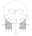
- an ellipse indicated by a long dashed double-short dashed line in FIGS. 2 and 3 shows a contact ellipse 40 that comes in contact with the ball 31 and a width of each of the contact areas 13 and 23 in an axial direction is equivalent to a major axis of the contact ellipse 40.
- lubricant retaining portions 17 are formed at the respective non-contact areas 14 of at least one of the inner ring raceway surface 12 and the outer ring raceway surface 22.
- the lubricant retaining portions 17 are formed at the respective non-contact areas 14 of the inner ring raceway surface 12.
- Each of the lubricant retaining portions 17 has recessed portions which retain a lubricant such as high viscosity grease or oil-containing polymer, and a large number of non-uniform projections and depressions formed in the bottom face of each recessed portion.
- a large number of recessed portions are formed in each of the lubricant retaining portions 17, and each of the recessed portions is formed by an independent dimple 15.
- the large number of non-uniform fine projections and depressions 16 are formed in the bottom face of each of the large number of dimples 15.
- the non-uniform projections and depressions 16 are projections and depressions that are formed without being arranged along a predetermined direction, that is, the non-uniform projections and depressions 16 are not projections and depressions that are formed along a predetermined direction by performing, for example, a cutting process.
- the non-uniform projections and depressions 16 are formed by performing a shot blasting treatment.
- the non-uniform projections and depressions 16 are formed by disposing depressions formed by particles of abrasive material, in the bottom face of each dimple 15.
- the shot blasting treatment it is possible to easily form the non-uniform projections and depressions 16 by using the shot blasting treatment, and it is possible to adjust the fineness of projections and depressions by appropriately changing the particle diameter of the abrasive material.
- the large number of dimples 15 as the recessed portions are formed over the entire non-contact areas 14. Further, when the shot blasting treatment is performed to form the fine projections and depressions 16, the contact area 13 is masked.
- the section of the contact area 13 of the inner ring raceway surface 12 is formed to be an arc groove having a curvature radius slightly larger than the radius of the ball 31, the section being taken along the axial direction.
- the section of each of the both non-contact areas 14 adjacent to the outer sides of the opposite end portions of the contact area 13 is formed to be an arc groove which is smoothly continuous with a corresponding one of opposite ends P of the arc groove of the contact area 13 (without a stepped surface), the section being taken along the axial direction. As shown in FIG.
- a center 02 of the arc of each of the arc grooves of the both non-contact areas 14 is set on a line L which passes through a corresponding one of the opposite ends P of the arc groove of the contact area 13 and a center O1 of the arc groove of the contact area 13.
- Each of the arc grooves of the both non-contact areas 14 is formed such that a separating distance between the arc groove of the non-contact area 14 and the ball 31 gradually increases toward an outside from an inside adjacent to a corresponding one of the opposite end portions of the contact area 13.
- the deep groove ball bearing as the rolling bearing according to the first embodiment is configured as described above. Therefore, a lubricant such as high viscosity grease or oil-containing polymer is applied onto the lubricant retaining portion 17 of the non-contact area 14 of the inner ring raceway surface 12 and the lubricant is retained in the large number of dimples 15 of the lubricant retaining portion 17. Further, the lubricant retaining portion 17 having the large number of dimples 15 is formed at the non-contact area 14, whereby lubricant retention ability can be increased, as compared to a case where the non-contact area 14 is formed to be a smooth surface.
- a lubricant such as high viscosity grease or oil-containing polymer
- the fine projections and depressions 16 are formed in the bottom faces of the large number of dimples 15, whereby the lubricant retention ability can be even more increased.
- the non-uniform projections and depressions 16 are formed without being arranged along a predetermined direction, in the bottom face of each dimple 15 as the recessed portion, whereby it is possible to suppress the flow of the lubricant in a predetermined direction, and it is possible to retain the lubricant in the depressions among the projections and depressions 16, and thus it is possible to even more increase the retention ability. Accordingly, it is possible to gradually supply the lubricant retained in the large number of dimples 15 to the contact area 13 of the inner ring raceway surface 12, and thus it is possible to maintain lubricating ability over a long period of time.
- the curvature radius R2 of the arc groove of the non-contact area 14 is set to be larger than the curvature radius R1 of the arc groove of the contact area 13, whereby the inclination of the non-contact area 14 becomes gentle, as compared to a case where the non-contact area 14 is formed to be an arc surface having the same center and the same radius as those of the contact area 13. For this reason, the lubricant retained in the large number of dimples 15 of the lubricant retaining portion 17 does not easily flow, and thus, the lubricant retention ability is high.
- the arc groove of the non-contact area 14 having the curvature radius R2 larger than the curvature radius R1 of the arc groove of the contact area 13 is formed such that a separating distance between the arc groove of the non-contact area 14 and the ball 31 gradually increases toward the outside from the inside adjacent to the outer side of the end portion of the contact area 13. For this reason, a larger quantity of lubricant can be retained in the non-contact area 14.
- lubricant retaining portions 117 are formed at respective non-contact areas 114 of an inner ring raceway surface 112, and each of the lubricant retaining portions 117 is formed by a recessed portion 119 and a large number of non-uniform projections and depressions 115.
- the recessed portion 119 is recessed in the non-contact area 114.
- the projections and depressions 115 are provided in the bottom face of the recessed portion 119.
- the recessed portion 119 is formed in a stepped manner over the entire non-contact area 114 such that the recessed portion 119 is recessed to be lower than a contact area 113 and reaches a raceway shoulder portion on one side.
- the lubricant flows out little by little to the contact area 113 along a slope of the recessed portion 119.
- the large number of projections and depressions 115 can be easily formed by shot blasting.
- the particle diameter of abrasive material used in the shot blasting in order to form the large number of projections and depressions 115 is smaller than the particle diameter of the abrasive material used in the shot blasting in the first embodiment.
- the curvature radius of an arc groove of the contact area 113 and the curvature radius of an arc groove of each of the both non-contact areas 114 are set so as to satisfy the relationship of "R1 ⁇ R2", where R1 is the curvature radius of the arc groove of the contact area 113 and R2 is the curvature radius of the arc groove of each of the both non-contact areas 114.
- R1 is the curvature radius of the arc groove of the contact area 113
- R2 is the curvature radius of the arc groove of each of the both non-contact areas 114.
- a lubricant such as high viscosity grease or oil-containing polymer is applied onto the lubricant retaining portion 117 of the non-contact area 114 of the inner ring raceway surface 112 and the lubricant is retained in the large number of non-uniform projections and depressions 115 in the lubricant retaining portion 117.
- the lubricant retaining portion 117 having the large number of projections and depressions 115 is formed at the non-contact area 114, whereby the lubricant retention ability can be increased, as compared to a case where the non-contact area 114 is formed to be a smooth surface.
- the invention is not limited to the first and second embodiments described above and can be implemented in various forms without departing from the scope of the invention.
- the case where the large number of projections and depressions 16 or 115 in the lubricant retaining portion 17 or 117 of the non-contact area 14 or 114 are formed by shot blasting has been described.
- the case where the lubricant retaining portion 17 or 117 is formed at the non-contact area 14 or 114 of the inner ring raceway surface 12 or 112 has been described.
- the invention may be implemented by forming the lubricant retaining portion at the non-contact area 14 or 114 of the inner ring raceway surface 12 or 112 and/or the non-contact area 24 of the outer ring raceway surface 22.
- the rolling bearing may be an angular contact ball bearing or a roller bearing.
- a roller is formed in a crowning shape.
- the curvature radius R2 of the arc groove of the non-contact area is set to be larger than the curvature radius R1 of the arc groove of the contact area, whereby the inclination of the non-contact area becomes gentle, as compared to the case where the non-contact area is formed to be the arc surface having the same center and the same radius as those of the contact area. For this reason, the lubricant retained in the lubricant retaining portion does not easily flow, and thus the lubricant retention ability is high.
- the arc groove of the non-contact area having the curvature radius R2 larger than the curvature radius R1 of the arc groove of the contact area is formed such that a separating distance between the arc groove of the non-contact area and the ball gradually increases toward the outside from the inside adjacent to the outer side of the end portion of the contact area, whereby a larger quantity of lubricant can be retained in the non-contact area.
Landscapes
- Engineering & Computer Science (AREA)
- General Engineering & Computer Science (AREA)
- Mechanical Engineering (AREA)
- Rolling Contact Bearings (AREA)
Applications Claiming Priority (1)
| Application Number | Priority Date | Filing Date | Title |
|---|---|---|---|
| JP2012205359A JP2014059030A (ja) | 2012-09-19 | 2012-09-19 | 転がり軸受 |
Publications (2)
| Publication Number | Publication Date |
|---|---|
| EP2711571A2 true EP2711571A2 (fr) | 2014-03-26 |
| EP2711571A3 EP2711571A3 (fr) | 2014-07-09 |
Family
ID=49212622
Family Applications (1)
| Application Number | Title | Priority Date | Filing Date |
|---|---|---|---|
| EP13184556.2A Withdrawn EP2711571A3 (fr) | 2012-09-19 | 2013-09-16 | Roulement avec poches de lubrifiant dans le chemin de roulement |
Country Status (4)
| Country | Link |
|---|---|
| US (1) | US8858086B2 (fr) |
| EP (1) | EP2711571A3 (fr) |
| JP (1) | JP2014059030A (fr) |
| CN (1) | CN103671555A (fr) |
Cited By (3)
| Publication number | Priority date | Publication date | Assignee | Title |
|---|---|---|---|---|
| CN112112888A (zh) * | 2020-09-23 | 2020-12-22 | 杭州电子科技大学 | 微织构自驱动油滴的脂润滑球轴承及其微织构加工方法 |
| CN112112889A (zh) * | 2020-09-23 | 2020-12-22 | 杭州电子科技大学 | 微织构辅助接触区润滑的深沟球轴承及其内外圈加工方法 |
| WO2023007043A1 (fr) * | 2021-07-29 | 2023-02-02 | Fersa Innova, S.L.U. | Roulement à rouleaux texturé |
Families Citing this family (11)
| Publication number | Priority date | Publication date | Assignee | Title |
|---|---|---|---|---|
| DE112015002288B4 (de) | 2014-05-15 | 2022-08-25 | The Timken Company | Lager und Verfahren zur Bildung eines Lagers |
| JP6536112B2 (ja) * | 2015-03-23 | 2019-07-03 | 株式会社ジェイテクト | 円すいころ軸受 |
| RS61689B1 (sr) * | 2015-04-13 | 2021-05-31 | Belenos Clean Power Holding Ag | Mašina sa kompresorom |
| PL3081816T3 (pl) * | 2015-04-13 | 2021-05-31 | Belenos Clean Power Holding Ag | Sprężarka z dwoma kulistymi elementami nośnymi wału |
| DE102015012332B4 (de) * | 2015-09-22 | 2022-09-08 | Gebrüder Reinfurt GmbH & Co. KG | Kugellagerbauform mit Kippkompensation |
| JP6728907B2 (ja) * | 2016-04-06 | 2020-07-22 | 株式会社ジェイテクト | 転がり軸受 |
| JP2018066453A (ja) * | 2016-10-21 | 2018-04-26 | 株式会社ジェイテクト | 転がり軸受 |
| CN110645264B (zh) * | 2019-08-12 | 2021-02-12 | 江苏大学 | 一种滚动轴承内圈滚道及滚动轴承 |
| IT201900021774A1 (it) * | 2019-11-21 | 2021-05-21 | Skf Ab | Gruppo mozzo ruota |
| CN114876960B (zh) * | 2022-04-18 | 2024-04-09 | 杭州电子科技大学 | 一种油脂自输运兼顾表面完整性的滚动轴承及其加工方法 |
| CN116221271A (zh) * | 2022-08-31 | 2023-06-06 | 广东极亚精机科技有限公司 | 谐波减速器 |
Citations (1)
| Publication number | Priority date | Publication date | Assignee | Title |
|---|---|---|---|---|
| JPH058045U (ja) | 1991-07-17 | 1993-02-02 | 日本精工株式会社 | アンギユラ形玉軸受 |
Family Cites Families (40)
| Publication number | Priority date | Publication date | Assignee | Title |
|---|---|---|---|---|
| US1269808A (en) | 1917-02-02 | 1918-06-18 | Hess Bright Mfg Co | Method of forming grooves in bearing-rings, &c. |
| US3161448A (en) * | 1963-07-05 | 1964-12-15 | Fafnir Bearing Co | Outer ring for antifriction bearing |
| US3370899A (en) | 1966-06-15 | 1968-02-27 | Phillip R. Eklund | Combination thrust and radial ball bearing |
| SU486161A2 (ru) | 1972-08-10 | 1975-09-30 | Государственный Научно-Исследовательский Институт Машиноведения | Шарикоподшипник |
| JP2508178B2 (ja) * | 1988-02-29 | 1996-06-19 | 日本精工株式会社 | 転がり軸受及びその製造方法 |
| US5498086A (en) * | 1995-01-31 | 1996-03-12 | Ou; Chin-Sung | Oil film-deposit bearing |
| SE509965C2 (sv) * | 1996-11-21 | 1999-03-29 | Skf Ab | Rullager med organ för att ge rullarna en positiv snedrullningsvinkel |
| JPH10227313A (ja) * | 1996-12-11 | 1998-08-25 | Nippon Seiko Kk | 転がり軸受 |
| JPH11241726A (ja) * | 1997-12-26 | 1999-09-07 | Ntn Corp | 転がり接触部品 |
| US6238744B1 (en) * | 1998-02-17 | 2001-05-29 | Ford Motor Company | Method for eliminating bearing assembly hoot noise |
| JP2000291665A (ja) * | 1999-04-06 | 2000-10-20 | Nsk Ltd | 転がり軸受 |
| JP2001208081A (ja) * | 2000-01-31 | 2001-08-03 | Nsk Ltd | 単列深溝型ラジアル玉軸受 |
| JP4284670B2 (ja) * | 2000-03-23 | 2009-06-24 | ミネベア株式会社 | 玉軸受及びその潤滑方法 |
| JP2002122149A (ja) * | 2000-10-12 | 2002-04-26 | Ntn Corp | アンギュラ玉軸受およびこれを用いた工作機械 |
| US6827496B2 (en) * | 2001-08-28 | 2004-12-07 | Koyo Seiko Co., Ltd. | Four-point contact ball bearing |
| JP2003074561A (ja) * | 2001-08-31 | 2003-03-12 | Nsk Ltd | 高速回転用転がり軸受 |
| EP1489317A1 (fr) * | 2002-02-20 | 2004-12-22 | Nsk Ltd., | Dispositif support de rotation pour poulie de compresseur |
| EP1357308B1 (fr) * | 2002-04-23 | 2009-12-23 | NSK Ltd., | Palier de roulement avec bague ou organes de roulement d'acier au chrome |
| EP1533533A1 (fr) * | 2002-06-25 | 2005-05-25 | Nsk Ltd., | Roulement a deux rangees de billes concu pour soutenir une poulie |
| JP2004176833A (ja) | 2002-11-28 | 2004-06-24 | Nsk Ltd | 玉軸受 |
| JP2005036864A (ja) * | 2003-07-18 | 2005-02-10 | Nsk Ltd | 玉軸受 |
| JP2005069271A (ja) * | 2003-08-28 | 2005-03-17 | Nsk Ltd | 転がり軸受 |
| JP2005090658A (ja) * | 2003-09-18 | 2005-04-07 | Nsk Ltd | 転がり軸受 |
| SE0302706L (sv) * | 2003-10-14 | 2005-01-25 | Skf Ab | En metod för åstadkommande av förbättrade rullkontaktytor |
| JP2005321048A (ja) * | 2004-05-10 | 2005-11-17 | Koyo Seiko Co Ltd | 転がり摺動部品およびその製造方法 |
| JP4442349B2 (ja) * | 2004-07-22 | 2010-03-31 | ブラザー工業株式会社 | 転がり軸受け及び主軸装置 |
| JP2006077950A (ja) * | 2004-09-13 | 2006-03-23 | Nsk Ltd | 転がり軸受 |
| KR20070083655A (ko) * | 2004-10-08 | 2007-08-24 | 엔티엔 가부시키가이샤 | 롤링 베어링 |
| DE102005018616A1 (de) | 2005-04-21 | 2006-10-26 | Schaeffler Kg | Schrägkugellager mit Schmiermittelspeicher |
| US20090129713A1 (en) * | 2005-07-13 | 2009-05-21 | Junichi Hattori | Angular Contact Ball Bearing and Joint Assembly for a Robotic Arm |
| CA2639786C (fr) * | 2006-01-23 | 2013-08-13 | Vestas Wind Systems A/S | Roulement, turbine eolienne et procedes de fabrication d'un roulement |
| JP2008045573A (ja) * | 2006-08-10 | 2008-02-28 | Nsk Ltd | 転がり摺動部材及びその製造方法並びに転動装置 |
| JP2008089025A (ja) | 2006-09-29 | 2008-04-17 | Nsk Ltd | リニアガイド装置 |
| JP2009002436A (ja) * | 2007-06-21 | 2009-01-08 | Nsk Ltd | 転がり摺動部材 |
| JP2009115187A (ja) | 2007-11-06 | 2009-05-28 | Ntn Corp | 転がり部材 |
| JP2009121659A (ja) | 2007-11-19 | 2009-06-04 | Ntn Corp | 転がり部材 |
| US8747012B2 (en) * | 2008-03-07 | 2014-06-10 | Federal-Mogul Corporation | Tie rod end with friction reducing coating |
| JP5565100B2 (ja) * | 2010-05-27 | 2014-08-06 | 株式会社ジェイテクト | ころ軸受 |
| CN102287443A (zh) * | 2011-06-07 | 2011-12-21 | 佛山市永力泰车轴有限公司 | 带储油分隔体的滚子轴承 |
| CN102287609A (zh) * | 2011-07-12 | 2011-12-21 | 江苏金风风电设备制造有限公司 | 低温旋转设备及其运行方法 |
-
2012
- 2012-09-19 JP JP2012205359A patent/JP2014059030A/ja active Pending
-
2013
- 2013-09-12 US US14/025,053 patent/US8858086B2/en not_active Expired - Fee Related
- 2013-09-16 EP EP13184556.2A patent/EP2711571A3/fr not_active Withdrawn
- 2013-09-16 CN CN201310421397.7A patent/CN103671555A/zh active Pending
Patent Citations (1)
| Publication number | Priority date | Publication date | Assignee | Title |
|---|---|---|---|---|
| JPH058045U (ja) | 1991-07-17 | 1993-02-02 | 日本精工株式会社 | アンギユラ形玉軸受 |
Cited By (3)
| Publication number | Priority date | Publication date | Assignee | Title |
|---|---|---|---|---|
| CN112112888A (zh) * | 2020-09-23 | 2020-12-22 | 杭州电子科技大学 | 微织构自驱动油滴的脂润滑球轴承及其微织构加工方法 |
| CN112112889A (zh) * | 2020-09-23 | 2020-12-22 | 杭州电子科技大学 | 微织构辅助接触区润滑的深沟球轴承及其内外圈加工方法 |
| WO2023007043A1 (fr) * | 2021-07-29 | 2023-02-02 | Fersa Innova, S.L.U. | Roulement à rouleaux texturé |
Also Published As
| Publication number | Publication date |
|---|---|
| EP2711571A3 (fr) | 2014-07-09 |
| US8858086B2 (en) | 2014-10-14 |
| JP2014059030A (ja) | 2014-04-03 |
| US20140079349A1 (en) | 2014-03-20 |
| CN103671555A (zh) | 2014-03-26 |
Similar Documents
| Publication | Publication Date | Title |
|---|---|---|
| US8858086B2 (en) | Rolling bearing | |
| EP2711572B1 (fr) | Roulement avec poches de lubrifiant dans le chemin de roulement | |
| US7771122B2 (en) | Cage for rolling bearing and rolling bearing having the same | |
| WO2009131139A1 (fr) | Roulement à billes | |
| JP2007051715A (ja) | 円錐ころ軸受、円錐ころ軸受装置及びこれを用いた車両用ピニオン軸支持装置 | |
| JP6422625B2 (ja) | 針状ころ軸受の保持器および針状ころ軸受構造 | |
| US9127716B2 (en) | Ball bearing | |
| JP2007051700A (ja) | 円錐ころ軸受、円錐ころ軸受装置及びこれを用いた車両用ピニオン軸支持装置 | |
| KR102348951B1 (ko) | 롤링 베어링 | |
| WO2013028284A1 (fr) | Cage de palier pour un ensemble roulement à rouleaux | |
| US10527096B2 (en) | Rolling bearing | |
| JP6267906B2 (ja) | 玉軸受用冠型保持器および玉軸受 | |
| JP5994369B2 (ja) | アンギュラ玉軸受 | |
| JP6191716B2 (ja) | アンギュラ玉軸受 | |
| US9689423B2 (en) | Rolling bearing | |
| JP2010286120A (ja) | 円錐ころ軸受の設計方法 | |
| KR102647697B1 (ko) | 텐덤 볼 베어링 | |
| JP4126529B2 (ja) | 円すいころ軸受 | |
| JP6115698B2 (ja) | 玉軸受用冠型保持器 | |
| JP5348271B2 (ja) | 玉軸受 | |
| JP2020153495A (ja) | 転がり軸受用保持器および転がり軸受 | |
| US20180335085A1 (en) | Ball bearing cage | |
| JP2016130583A (ja) | アンギュラ玉軸受 | |
| CN104121284A (zh) | 具有轴向相邻滚子的滚动轴承 | |
| JP6003022B2 (ja) | 転がり軸受用保持器 |
Legal Events
| Date | Code | Title | Description |
|---|---|---|---|
| PUAI | Public reference made under article 153(3) epc to a published international application that has entered the european phase |
Free format text: ORIGINAL CODE: 0009012 |
|
| AK | Designated contracting states |
Kind code of ref document: A2 Designated state(s): AL AT BE BG CH CY CZ DE DK EE ES FI FR GB GR HR HU IE IS IT LI LT LU LV MC MK MT NL NO PL PT RO RS SE SI SK SM TR |
|
| AX | Request for extension of the european patent |
Extension state: BA ME |
|
| PUAL | Search report despatched |
Free format text: ORIGINAL CODE: 0009013 |
|
| AK | Designated contracting states |
Kind code of ref document: A3 Designated state(s): AL AT BE BG CH CY CZ DE DK EE ES FI FR GB GR HR HU IE IS IT LI LT LU LV MC MK MT NL NO PL PT RO RS SE SI SK SM TR |
|
| AX | Request for extension of the european patent |
Extension state: BA ME |
|
| RIC1 | Information provided on ipc code assigned before grant |
Ipc: F16C 33/66 20060101AFI20140605BHEP Ipc: F16C 19/06 20060101ALN20140605BHEP Ipc: F16C 33/58 20060101ALI20140605BHEP |
|
| 17P | Request for examination filed |
Effective date: 20150107 |
|
| RBV | Designated contracting states (corrected) |
Designated state(s): AL AT BE BG CH CY CZ DE DK EE ES FI FR GB GR HR HU IE IS IT LI LT LU LV MC MK MT NL NO PL PT RO RS SE SI SK SM TR |
|
| STAA | Information on the status of an ep patent application or granted ep patent |
Free format text: STATUS: THE APPLICATION HAS BEEN WITHDRAWN |
|
| 18W | Application withdrawn |
Effective date: 20170301 |