EP2708334B1 - Vorrichtung und verfahren zur steuerung der vorhersage von bewegungen - Google Patents
Vorrichtung und verfahren zur steuerung der vorhersage von bewegungen Download PDFInfo
- Publication number
- EP2708334B1 EP2708334B1 EP12782445.6A EP12782445A EP2708334B1 EP 2708334 B1 EP2708334 B1 EP 2708334B1 EP 12782445 A EP12782445 A EP 12782445A EP 2708334 B1 EP2708334 B1 EP 2708334B1
- Authority
- EP
- European Patent Office
- Prior art keywords
- robot
- robots
- internal state
- state
- prediction
- Prior art date
- Legal status (The legal status is an assumption and is not a legal conclusion. Google has not performed a legal analysis and makes no representation as to the accuracy of the status listed.)
- Active
Links
- 230000033001 locomotion Effects 0.000 title claims description 133
- 238000000034 method Methods 0.000 title claims description 51
- 238000012545 processing Methods 0.000 claims description 93
- 238000013500 data storage Methods 0.000 claims description 77
- 230000007704 transition Effects 0.000 claims description 36
- 238000003860 storage Methods 0.000 claims description 19
- 230000010391 action planning Effects 0.000 claims description 10
- 238000012546 transfer Methods 0.000 claims description 8
- 230000014759 maintenance of location Effects 0.000 claims 3
- 238000005259 measurement Methods 0.000 description 95
- 230000036544 posture Effects 0.000 description 42
- 230000014509 gene expression Effects 0.000 description 27
- 238000004891 communication Methods 0.000 description 25
- 238000004364 calculation method Methods 0.000 description 21
- 238000009826 distribution Methods 0.000 description 15
- 239000011159 matrix material Substances 0.000 description 14
- 238000010586 diagram Methods 0.000 description 12
- 230000008569 process Effects 0.000 description 12
- 230000001133 acceleration Effects 0.000 description 6
- 230000006870 function Effects 0.000 description 6
- 230000001419 dependent effect Effects 0.000 description 5
- 238000013459 approach Methods 0.000 description 3
- 230000005540 biological transmission Effects 0.000 description 3
- 230000005484 gravity Effects 0.000 description 3
- 230000007246 mechanism Effects 0.000 description 3
- 239000002245 particle Substances 0.000 description 3
- 230000000007 visual effect Effects 0.000 description 3
- 230000008859 change Effects 0.000 description 2
- 238000013461 design Methods 0.000 description 2
- 238000000691 measurement method Methods 0.000 description 2
- 238000012544 monitoring process Methods 0.000 description 2
- 235000008733 Citrus aurantifolia Nutrition 0.000 description 1
- 235000011941 Tilia x europaea Nutrition 0.000 description 1
- 238000006243 chemical reaction Methods 0.000 description 1
- 230000000295 complement effect Effects 0.000 description 1
- 238000012937 correction Methods 0.000 description 1
- 238000001514 detection method Methods 0.000 description 1
- 230000000694 effects Effects 0.000 description 1
- 238000005516 engineering process Methods 0.000 description 1
- 230000001747 exhibiting effect Effects 0.000 description 1
- 238000001914 filtration Methods 0.000 description 1
- 239000004571 lime Substances 0.000 description 1
- 238000004519 manufacturing process Methods 0.000 description 1
- 230000002035 prolonged effect Effects 0.000 description 1
- XLYOFNOQVPJJNP-UHFFFAOYSA-N water Substances O XLYOFNOQVPJJNP-UHFFFAOYSA-N 0.000 description 1
Images

Classifications
-
- B—PERFORMING OPERATIONS; TRANSPORTING
- B25—HAND TOOLS; PORTABLE POWER-DRIVEN TOOLS; MANIPULATORS
- B25J—MANIPULATORS; CHAMBERS PROVIDED WITH MANIPULATION DEVICES
- B25J13/00—Controls for manipulators
- B25J13/08—Controls for manipulators by means of sensing devices, e.g. viewing or touching devices
-
- B—PERFORMING OPERATIONS; TRANSPORTING
- B25—HAND TOOLS; PORTABLE POWER-DRIVEN TOOLS; MANIPULATORS
- B25J—MANIPULATORS; CHAMBERS PROVIDED WITH MANIPULATION DEVICES
- B25J19/00—Accessories fitted to manipulators, e.g. for monitoring, for viewing; Safety devices combined with or specially adapted for use in connection with manipulators
- B25J19/02—Sensing devices
- B25J19/021—Optical sensing devices
- B25J19/023—Optical sensing devices including video camera means
-
- B—PERFORMING OPERATIONS; TRANSPORTING
- B25—HAND TOOLS; PORTABLE POWER-DRIVEN TOOLS; MANIPULATORS
- B25J—MANIPULATORS; CHAMBERS PROVIDED WITH MANIPULATION DEVICES
- B25J5/00—Manipulators mounted on wheels or on carriages
- B25J5/007—Manipulators mounted on wheels or on carriages mounted on wheels
-
- B—PERFORMING OPERATIONS; TRANSPORTING
- B25—HAND TOOLS; PORTABLE POWER-DRIVEN TOOLS; MANIPULATORS
- B25J—MANIPULATORS; CHAMBERS PROVIDED WITH MANIPULATION DEVICES
- B25J9/00—Programme-controlled manipulators
- B25J9/16—Programme controls
- B25J9/1656—Programme controls characterised by programming, planning systems for manipulators
- B25J9/1664—Programme controls characterised by programming, planning systems for manipulators characterised by motion, path, trajectory planning
-
- B—PERFORMING OPERATIONS; TRANSPORTING
- B25—HAND TOOLS; PORTABLE POWER-DRIVEN TOOLS; MANIPULATORS
- B25J—MANIPULATORS; CHAMBERS PROVIDED WITH MANIPULATION DEVICES
- B25J9/00—Programme-controlled manipulators
- B25J9/16—Programme controls
- B25J9/1694—Programme controls characterised by use of sensors other than normal servo-feedback from position, speed or acceleration sensors, perception control, multi-sensor controlled systems, sensor fusion
- B25J9/1697—Vision controlled systems
-
- G—PHYSICS
- G05—CONTROLLING; REGULATING
- G05B—CONTROL OR REGULATING SYSTEMS IN GENERAL; FUNCTIONAL ELEMENTS OF SUCH SYSTEMS; MONITORING OR TESTING ARRANGEMENTS FOR SUCH SYSTEMS OR ELEMENTS
- G05B2219/00—Program-control systems
- G05B2219/30—Nc systems
- G05B2219/32—Operator till task planning
- G05B2219/32357—Simulation of material handling, flexible conveyor system fcs
-
- G—PHYSICS
- G05—CONTROLLING; REGULATING
- G05B—CONTROL OR REGULATING SYSTEMS IN GENERAL; FUNCTIONAL ELEMENTS OF SUCH SYSTEMS; MONITORING OR TESTING ARRANGEMENTS FOR SUCH SYSTEMS OR ELEMENTS
- G05B2219/00—Program-control systems
- G05B2219/30—Nc systems
- G05B2219/37—Measurements
- G05B2219/37436—Prediction of displacement, relative or absolute, motion
-
- G—PHYSICS
- G05—CONTROLLING; REGULATING
- G05B—CONTROL OR REGULATING SYSTEMS IN GENERAL; FUNCTIONAL ELEMENTS OF SUCH SYSTEMS; MONITORING OR TESTING ARRANGEMENTS FOR SUCH SYSTEMS OR ELEMENTS
- G05B2219/00—Program-control systems
- G05B2219/30—Nc systems
- G05B2219/40—Robotics, robotics mapping to robotics vision
- G05B2219/40512—Real time path planning, trajectory generation
-
- G—PHYSICS
- G05—CONTROLLING; REGULATING
- G05B—CONTROL OR REGULATING SYSTEMS IN GENERAL; FUNCTIONAL ELEMENTS OF SUCH SYSTEMS; MONITORING OR TESTING ARRANGEMENTS FOR SUCH SYSTEMS OR ELEMENTS
- G05B2219/00—Program-control systems
- G05B2219/30—Nc systems
- G05B2219/41—Servomotor, servo controller till figures
- G05B2219/41146—Kalman filter
-
- G—PHYSICS
- G05—CONTROLLING; REGULATING
- G05B—CONTROL OR REGULATING SYSTEMS IN GENERAL; FUNCTIONAL ELEMENTS OF SUCH SYSTEMS; MONITORING OR TESTING ARRANGEMENTS FOR SUCH SYSTEMS OR ELEMENTS
- G05B2219/00—Program-control systems
- G05B2219/30—Nc systems
- G05B2219/42—Servomotor, servo controller kind till VSS
- G05B2219/42263—Different sample rates, multiple sample rates for the different loops
-
- Y—GENERAL TAGGING OF NEW TECHNOLOGICAL DEVELOPMENTS; GENERAL TAGGING OF CROSS-SECTIONAL TECHNOLOGIES SPANNING OVER SEVERAL SECTIONS OF THE IPC; TECHNICAL SUBJECTS COVERED BY FORMER USPC CROSS-REFERENCE ART COLLECTIONS [XRACs] AND DIGESTS
- Y02—TECHNOLOGIES OR APPLICATIONS FOR MITIGATION OR ADAPTATION AGAINST CLIMATE CHANGE
- Y02P—CLIMATE CHANGE MITIGATION TECHNOLOGIES IN THE PRODUCTION OR PROCESSING OF GOODS
- Y02P90/00—Enabling technologies with a potential contribution to greenhouse gas [GHG] emissions mitigation
- Y02P90/02—Total factory control, e.g. smart factories, flexible manufacturing systems [FMS] or integrated manufacturing systems [IMS]
Definitions
- the present invention relates to motion prediction control device and method adapted to predict the motion of a workpiece or a robot in an automated apparatus using a robot or the like.
- a control device adapted to control the drive of a robot by calculating the position or the posture of the robot by using information from sensors installed on the robot or outside the robot
- the following sensors and measurement methods are generally used to measure the position and the posture of a robot.
- a gyro sensor mounted on a robot, or an encoder or the like on a wheel is used to measure the velocity, the acceleration, the angular velocity or the like of the robot.
- a steering angle of a robot is measured by an encoder or the like of a steering unit mounted on the robot.
- a range sensor (a laser range finder (LRF), laser radar or the like), a camera, or the like mounted on a robot is used to measure the position or the posture of a landmark around the robot.
- LRF laser range finder
- a camera or the like mounted on a robot is used to measure the position or the posture of a landmark around the robot.
- One or both of the current position and posture are measured by a GPS compass or the like installed on the robot.
- a range sensor, a camera, or the like installed outside a robot is used to measure the position or the posture of the robot within a measurement range.
- the position and the posture measured in the above-described methods (2) and (3) are relative position and posture indicated by a coordinate system whose origin is a particular point or the sensor used for measurement. Each origin of measurement coordinates is different, and in the case of a sensor on a robot, the position of the robot itself that becomes the origin is unknown, thus making it difficult to compare the measurement results simply by coordinate conversion or the like.
- the above-described method (1) is not intended to directly measure the position or the posture, so that direct comparison with the methods (2) and (3) is impossible.
- a visual sensor such as a camera, or a range sensor such as a laser range finder (LRF), installed on the robot or outside the robot, and then to carry out follow-up control on a robot arm according to the measurement results.
- LRF laser range finder
- Methods for measuring the position of the robot include a method for measuring the position relative to a landmark by a sensor on the robot, and a method for directly measuring the position of the robot by a sensor installed outside the robot, as described above.
- a moving workpiece or a mobile robot will be also referred to simply as "a mobile object" in some cases.
- the relative position between an object (a workpiece or a landmark) and the robot, which changes from moment to moment, is measured at a predetermined cycle (e.g., by a 30-fps camera), and a movement command to, for example, move the robot close to the workpiece, is output to the robot on the basis of the measurement results.
- a predetermined cycle e.g., by a 30-fps camera
- the robot even when the robot is operated, aiming at the measured position of the workpiece, the robot possibly fails to follow the moving workpiece due to a control delay which includes a measurement delay of the sensor, a delay in acquiring data, and a motional delay of the robot.
- the measurement cycle of the sensor is generally longer than a control cycle (e.g., 4 ms) of the robot. Therefore, the robot will not obtain the up-to-date measurement result in each control cycle, which leads to a measurement delay accordingly.
- the cycle in which the measurement result is updated is further prolonged and also becomes non-constant.
- devices handling a moving workpiece or a mobile robot cause a problem in that the follow-up performance of a robot deteriorates due to a control delay.
- Patent Literatures 1 to 5 To solve the problem with the background art described above, various control means have already been proposed (e.g., Patent Literatures 1 to 5).
- Patent Literature (PLT) 1 is adapted to estimate motion parameters from the positional data of an object that performs simple harmonic motions, predict a future position thereof, and grasp the object by a manipulator on the basis of the positional information.
- the "STATE ESTIMATION MEANS" in PLT 2 is adapted to estimate an internal state of a system which has performed observation, on the basis of observation signals input in time series by observation.
- the internal state means a state variable such as the position, the posture, and deflection angle of an object.
- the "MOTION PREDICTION DEVICE” in PLT 3 combines background processing and foreground processing to carry out automatic tracking and motion prediction.
- the "ROBOT DEVICE AND CONTROL METHOD THEREFOF" in PLT 4 proposes a method in which an arm is first caused to follow an object, and a destination of the object is predicted by making use of the coincidence between the motion state of the arm at the time of the follow-up and the motion state of the object.
- predicting the destination of the object by considering the motion state of the arm enables the grasping of a mobile object.
- PTL 5 proposes a further visual servo prediction control scheme for achieving high speed tracking and high control accuracy.
- the motion state of an object is estimated from the observation history of the measurement of the object (an object to be measured or a workpiece), thereby making it possible to complement data for time during which no measurement value has been obtained, or to predict a grasping point for the robot to grasp the object.
- a Bayesian filter such as a Kalman filter or a particle filter is generally used to estimate the motion state.
- the Bayesian filter defines the state of a motion (the velocity, the acceleration, or the like of an object) as “an internal state,”, also previously defines a “state transition model” indicating how the internal state changes with time, and then defines an "observation equation,” as disclosed in PTL2.
- the processing that implements the Bayesian filter is roughly divided into the following two types of processing.
- a robot controller is influenced by the time required for processing to update a motion state (internal state), possibly making it difficult to calculate a control command value at a predetermined control cycle and to control the robot. For example, there are the following problems.
- the update processing may not be finished within the control cycle of the robot.
- the update processing in the state estimation device generally takes time, and takes extra time especially in the case where many types of measurement values are involved or in the case where a particle filter or other complicated processing is involved.
- the means described in PTL2 is capable of reducing calculation amount in accordance with a purpose by separating the prediction processing and the update processing in accordance with the type of an observation value or a state variable. However, if a complicated motion is involved, or if all obtained measurement values are desired to be reflected, then every processing is eventually required to be combined, so that the calculation amount required for estimation will not be reduced.
- the estimation device is required, upon a request from the robot for a prediction value, to complete the prediction processing and supply a prediction value within predetermined time.
- the problems described above may make it difficult to calculate a control command value at a determined control cycle so as to control a robot, as described above.
- an object of the present invention is to provide a motion prediction control device and method that can generate a control command value at a predetermined control cycle without being influenced by time required for the processing of updating an internal state in the case where an internal state of one or both of an object and a robot is estimated, and a prediction value (control command value) required for controlling a robot is generated on the basis of the estimated internal state.
- a motion prediction control device according to claim 1.
- a preferred embodiment is set out in dependent claim 2.
- a preferred embodiment is set out in dependent claim 8.
- the sensor information on one or both of the object and the robot is acquired at an arbitrary timing that is independent of the control cycle of the robot, and the internal state of one or both of the object and the robot is predicted and updated on the basis of the sensor information, thus eliminating the need for updating the internal state within the control cycle of the robot.
- the prediction value is predicted on the basis of the latest internal state stored in the data storage unit, and the robot is controlled in real time, thus making it possible to calculate a prediction value necessary for controlling the robot (a control command value) at a predetermined control cycle to control the robot without being influenced by the calculation amount for estimating the state.
- the robot control unit can generate a control command value at a predetermined control cycle without being influenced by the time required for the processing of updating the internal state.
- FIG. 1 illustrates a first configuration example of a robot system provided with a motion prediction control device according to a first embodiment of the present invention.
- the reference sign 1 denotes a workpiece
- the reference sign 2 denotes a movable robot
- the reference sign 3 denotes a robot arm
- the reference sign 4 denotes a hand
- the reference sign 5a denotes a first camera secured to the hand 4
- the reference sign 5b denotes a second camera secured at an external fixed position
- the reference sign 6 denotes a fixed landmark
- the reference sign 10 denotes a motion prediction control device of the first embodiment.
- the workpiece 1 and the landmark 6 will be both referred to as "the object.”
- the robot system is configured such that the workpiece 1 that moves while performing a pendular motion, or the fixed landmark 6 is measured by the cameras 5a and 5b, the robot 2 is measured by the camera 5b, and the robot 2 is controlled to follow the workpiece 1 to grasp the workpiece 1 by the hand 4.
- the position of the landmark 6 is not required to be known.
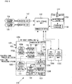
- FIG. 2 illustrates a first configuration example of the motion prediction control device according to the first embodiment of the present invention.
- the motion prediction control device 10 of the first embodiment includes a measuring unit 12, a state estimation unit 14, a data storage unit 16, and a robot control unit 20.
- the units 12, 14 and 20 are connected to the data storage unit 16.
- the measuring unit 12 measures the relative relationship between an object and the robot 2.
- the measurement result of the relative position and posture between the object and the robot, for example, measured by the measuring unit 12 is denoted by a measurement value Y.
- Each measurement value Y is defined in accordance with the type of the measuring unit or an object to be measured.
- the measurement value Y depends on the object to be measured (the workpiece 1, the landmark 6, or the mobile robot 2) or the type of the measuring unit.
- the relative relationship is information including a position, a posture, a velocity, an angular velocity, acceleration, and angular acceleration.
- the measuring unit 12 in this example is constituted by three measuring units (a first measuring unit 12a, a second measuring unit 12b, and a third measuring unit 12c) that are connected to the first camera 5a, the second camera 5b, and the robot control unit 20, respectively.
- two cameras and two measuring units are used as follows.
- An image of the object is obtained through the first camera 5a and the second camera 5b, and the measurement value Y of the object is determined by image processing.
- the measuring unit 12b obtains also an image of the robot 2 to determine the measurement value Y of the robot 2 by image processing.
- the measuring unit 12c measures the movement amount of a tire of the robot 2 or the rotational amount of an arm joint by an encoder to determine the measurement value Y of the robot 2.
- the determined measurement values Y of one of or both of the object and the robot 2 are stored in the data storage unit 16.
- the measuring unit 12 is not limited to the configuration described above, and may alternatively use a unit capable of measuring the relative relationship between the object and the robot 2 such as a laser radar, an acceleration sensor, a gyro sensor, and a velocity sensor.
- a unit capable of measuring the relative relationship between the object and the robot 2 such as a laser radar, an acceleration sensor, a gyro sensor, and a velocity sensor.
- a state estimation algorithm based on the algorithm of a Kalman filter is installed in the state estimation unit 14. According to this algorithm, all of state variables are referred to as an internal state X, together. These state variables include the deflection angle ⁇ and ⁇ of the pendulum by which the workpiece 1 is suspended, the positions of supporting points x, y and z of the pendulum, the positions X1, Y1 and Z1 of the landmark 6, the postures RX1, RY1 and RZ1 of the landmark 6, the positions Xr, Yr and Zr of the robot 2, and the postures thereof RXr, RYr and RZr of the robot 2.
- a state transition equation X (t+ ⁇ t) f(X(t)) that indicates how the internal state X changes as time elapses
- an observation equation Y h(X) that associates the internal state X with the measurement value Y
- the algorithm also manages mainly an error distribution C ov X of the internal state X and an error distribution C ov Y of a measurement value. From these data, the accuracy of a state estimation can be determined. In the examples described below, the accuracy index values will be all denoted by E.
- the state estimation unit 14 includes an entire prediction section 15a that predicts the internal state of one or both of the object and the robot 2, and an updating section 15b that updates the internal state stored in the data storage unit 16, to predict and update the internal state of one or both of the object and the robot 2.
- the entire prediction section 15a carries out calculation to cause the internal state X recorded in the data storage unit 16 to proceed to specified time by using the state transition equation f(X).
- the updating section 15b uses the internal state X in the data storage unit 16 and the observation equation h(X) to calculate a prediction value of the measurement value Y of one or both of the object and the robot 2.
- the input measurement value Y and the prediction value are compared with each other to update the internal state X, and the updated internal state X is recorded in the data storage unit 16.
- the accuracy index value E of the state estimation is also updated at the same time and recorded in the data storage unit 16.
- the measuring unit 12, the state estimation unit 14, and the data storage unit 16 are non-real-time processing systems that work at different timings from the control cycle of the robot 2.
- the processing intervals of the non-real-time processing systems may be longer than the control cycle of the robot 2, and the cycle thereof may not be fixed.
- the processing interval is, for example, 30 to 80 ms.
- the relative relationship e.g., the relative position and posture
- the relative relationship e.g., the relative position and posture
- the internal state of one or both of the object and the robot 2 is predicted and updated, and the updated internal state and the state transition equation used for the prediction are stored.
- the robot control unit 20 in this example includes a receiver 21, a command value calculator 22, a transmitter 23, and an on-robot predictor 24.
- the receiver 21 receives from the robot 2 the position information thereof (encoder information or the like) .
- the command value calculator 22 calculates a command value for the robot 2 on the basis of a prediction value supplied by the on-robot. predictor 24.
- the prediction value is, for example, the present position or the future position of the workpiece 1 or the robot 2.
- the transmitter 23 transmits a calculated command value to the robot 2.
- the on-robot predictor 24 predicts, at a predetermined control cycle, a prediction value required for controlling the robot 2.
- the robot control unit 20 includes the on-robot predictor 24 that carries out prediction processing (prediction) for obtaining a prediction value required to control the robot 2.
- the on-robot predictor 24 has only to predict an internal amount (prediction value) related to the control of the robot 2 and does not have to predict all internal amounts.
- the robot control unit 20 transmits a motion command to the robot 2 at a fixed cycle (e.g., 4 ms), and receives encoder information and the like of the robot 2.
- the received position information is acquired by the above-mentioned measuring unit 12c, and becomes the measurement value Y of the mobile robot 2.
- the on-robot predictor 24 is used to predict the present and future motional states of one or both of the object and the robot 2, and the predicted motional states are used to calculate a command value.
- the on-robot predictor 24 carries out calculation to shift the state amount that is related to the robot control and that is included in the internal state X recorded in the data storage unit 16, to specified time by using the state transition equation f(X).
- the data storage unit 16 holds the data on the above-mentioned internal state X, model time tx of an internal state, the measurement value Y, measured time ty, the state transition equation f, the observation equation h, the accuracy index value E of a state estimation, and the like.
- the robot control unit 20 described above is a real-time processing system controlled at the control cycle of the robot 2.
- the control cycle is a fixed cycle that is shorter than the processing interval of the above-mentioned non-real-time processing system.
- the control cycle is, for example, 3 to 4 ms.
- the robot control unit 20 predicts, at the control cycle of the robot 2, a prediction value necessary for the control so as to control the robot 2 in real time at the control cycle of the robot 2.
- the measuring unit 12 measures one or both of the object and the robot 2 at an arbitrary timing, and records the measurement result in the data storage unit 16 as sensor information.
- the state estimation unit 14 estimates the internal state by prediction processing and update processing (Correction).
- the calculated internal state, a state transition equation used for the estimation, and the like are recorded in the data storage unit 16.
- the robot control unit 20 controls the robot 2 at a predetermined control cycle.
- the on-robot predictor 24 is used to calculate the predicted position of one or both of the object and the robot 2 at arbitrary time, and the predicted position is used for the control.
- the on-robot predictor 24 carries out the prediction processing by using the latest internal state and the state transition model recorded in the data storage unit 16.
- the robot control unit 20 operates as a real-time processing system that carries out processing at a predetermined control cycle.
- the remaining units may be non-real-time processing systems that do not have time limits of fixed cycles.
- the two measuring units repeat the following steps (1) to (3) at an arbitrary timing.
- FIG. 3 illustrates a second configuration example of the motion prediction control device according to the first embodiment of the present invention.
- This example is suitable for a case where the time required for the communication between the robot control unit 20 and the data storage unit 16 is long.
- the data storage unit 16 has a function for transferring the latest internal state stored in the data storage unit 16 to an on-robot storage 26 at a timing that is independent of a request from the robot 2.
- the data storage unit 16 transfers the internal state and the state transition model recorded in the data storage unit 16 to the on-robot storage 26.
- the on-robot predictor 24 carries out processing by referring to the data in the on-robot storage 26.
- the transfer timing is preferably the moment when the internal state X of the data storage unit 16 is updated (immediately after the step (6)).
- This data transfer is performed upon detection of new data having been recorded in the data storage unit 16 (immediately after step (6)) or at fixed time intervals. Alternatively, this data transfer may be performed at both of the above-mentioned timings.
- the contents of the data storage unit 16 are sequentially transferred to the on-robot storage 26, and the on-robot predictor 24 refers to the on-robot storage 26, thus eliminating the need for communication for the calculation of the step (8).
- FIG. 4 illustrates a second configuration example of a robot system provided with a motion prediction control device according to the first embodiment.
- This example differs from the first configuration example of the robot system in that the robot 2 is fixed and the landmark 6 is not included.
- the rest of the configuration is the same as the first configuration example.
- this example illustrates a case where the moving workpiece 1 is grasped by the arm 3 of the robot 2 that is fixed, and differs from the first configuration example of the robot system in the aspect that no estimation related to the robot 2 is required.
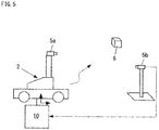
- FIG. 5 illustrates a third configuration example of the robot system provided with the motion prediction control device according to the first embodiment.
- This example illustrates a case where the robot 2 estimates its own position from the landmark 6 of which position is known, and the example differs from the first configuration example in that there is no need to perform estimations related to a workpiece and the estimations of the position and posture of the landmark 6.
- This example illustrates a case where the mobile robot 2 measures the landmark 6 of which position is known, to estimate its own position of the robot 2.
- the internal amounts X to be estimated are the its own position (X r , Y r , Z r ) of the robot 2 and the posture (R xr , R yr , R zr ) of the robot 2.
- the steering angle, the velocity, the angular velocity, and the like of a wheel may be estimated.
- the result of the measurement of the landmark 6 by the camera 5a, the result of the measurement of the position of the robot 2 by the camera 5b, the rotational amount (0) of the wheel recorded by the robot control unit 20, and the like are included in the measurement values used in the update processing.
- the remaining aspects of the third configuration example of the robot system may be the same as the first configuration example of the robot system.
- the first embodiment of the present invention is not limited to the configuration examples described above.
- the estimation of the motional states of the workpieces and the estimation of the motional states of the robots are combined, thus making it possible to achieve a system that takes the time limits in the robot control into account by the first embodiment described above.
- the workpiece that performs a pendular motion and the wheeled mobile robot are shown.
- the mode of movement is not limited thereto.
- the workpiece may move on a conveyor, float on water or fly.
- the robot may be a crawler type or a type that travels on a rail.
- the "movement" of the fixed arm includes a case where the base thereof shakes or passively moves.
- the units do not have to be divided into separate processing units.
- a plurality of programs such as a measurement program and a state estimation program may be concurrently run on a single personal computer.
- the robot control unit is a real-time processing system that carries out processing under the limitation of a fixed cycle.
- a real-time operating system allows a program for non-real-time processing and a program for real-time processing to be concurrently run.
- the data storage unit 16 may be any memory as long as it is a shared memory from which the same data is read by a plurality of units or programs and to which the same data is written by a plurality of units or programs. This obviates the need to set the data storage unit 16 as an independent unit.
- the data storage unit 16 may be prepared in a memory space of the state estimation unit 14 or the measuring unit 12.
- the measuring unit 12, the state estimation unit 14, and the data storage unit 16 measure the relative relationship between an object and a robot (e.g., a relative position), predict and update the internal state of one or both of the object and the robot, and store the updated internal state and the state transition equation used for the prediction.
- a mobile body e.g., a workpiece or a mobile robot
- a measurement result of the relative relationship e.g., a position or a posture
- the robot control unit 20 includes the on-robot predictor 24 that predicts a prediction value necessary for controlling the robot 2 at the control cycle of the robot 2 to predict the prediction value at the control cycle on the basis of the latest internal state stored in the data storage unit 16, and control the robot 2 in real time. This allows a control command value to be calculated at a control cycle determined for each robot without being influenced by the calculation amount of a state estimation, thereby controlling the robot 2.
- the robot control unit 20 can operate without being subjected to the influence of time required for the update processing of the state estimation.
- each robot control unit 20 independently carries out the prediction calculation, so that the time required for the prediction processing will not be increased. This obviates the need for reviewing the design of an arithmetic processing capability and the like when changing the system.
- the time limit of the prediction processing can be set for each robot control unit 20.
- the accuracy of a prediction value to be calculated, the type of a prediction value, and the like can be also set for each robot control unit 20.
- ingenuities such as changing the accuracy of the prediction calculation or calculating only a necessary variable in an internal state can be implemented in each robot 2 by taking into account the time required for the prediction processing, the control cycle, and the like,.
- the data storage unit 16 transfers the latest internal state stored in the data storage unit 16 to the on-robot storage 26 at a timing that does not depend on a request from the robot 2, thus permitting prompt reference to data required for the prediction processing in the case where the communication between the robot control unit 20 and the state estimation unit 14 takes time or in the case where the time required for the communication is not consistent.
- the prediction processing can be completed within predetermined time although the data referred to on the robot 2 is not necessarily the latest value due to the influence of a communication delay.
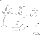
- FIG. 6 is a schematic diagram illustrating a robot system provided with a motion prediction control device according to a second embodiment of the present invention.
- the reference sign 101 denotes a mobile robot
- the reference sign 102 denotes a landmark fixed outside the mobile robot 101
- the reference sign 103 denotes an internal sensor secured to the mobile robot 101
- the reference sign 104 denotes an external sensor fixed outside the mobile robot 101.
- each of a plurality of mobile robots 101 is adapted to autonomously travel.
- the mobile robot will be referred to simply as "the robot" in the second embodiment.
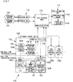
- FIG. 7 illustrates a first configuration example of the motion prediction control device according to the second embodiment of the present invention.
- a motion prediction control device 110 of the second embodiment includes a measuring unit 112, a state estimation unit 114, a data storage unit 116, and a plurality of robot control units 120.
- the units 112, 114, and 120 are all directly connected to the data storage unit 116.
- the plurality of robot control units 120 in this example includes a first robot control unit 120A, a second robot control unit 120B, and a third robot control unit 120C.
- robot control units 120 there are three robot control units 120. However, there may be two or four or more robot control units 120.
- the measuring unit 112 is connected to the corresponding external sensor 104 to obtain sensor information (observation values) of the external sensor 104.
- the external sensor 104 may be a camera, a laser range finder (LRF), a three-dimensional laser radar, a gyro sensor, a GPS compass, a pulse encoder, or the like.
- the measuring unit 112 reads sensor information from the external sensor 104 at an arbitrary timing, and carries out measurement processing (the steps(1) to (3) of the operation) that will be discussed later.
- a measuring section 124 on the robot control unit 120 has the same function as that of the measuring unit 112. Further, in this example, the unit that has no processor for travel mechanism or drive control in the configuration of the robot control unit 120, which will be discussed later, will be referred to as "the measuring unit 112.”
- a state estimation algorithm based on the algorithm of a Kalman filter is installed in the state estimation unit 114.
- the algorithm defines all state variables, including a position x, y, z, a velocity vx, vy, vz, and an angular velocity drx, dry, drz of the robot 101, as an internal state X.
- a state transition equation X (t+ ⁇ t) f(X(t)) that indicates how the internal state X changes as time elapses
- an observation equation Y h(X) that associates the internal state X with an observation value Y
- the observation equation is defined for each type of the observation value Y (sensor information).
- the algorithm also manages mainly an error distribution C ov X of the internal state X and an error distribution C ov Y of the observation value Y. From these data, the accuracy of a state estimation can be determined. In the examples described below, the accuracy index values will be denoted by E, together.
- the state estimation unit 114 includes two functions, namely, an entire prediction section 115a and an updating section 115b.
- the entire prediction section 115a carries out calculation to cause the internal state X recorded in the data storage unit 116 to proceed to specified time by using the state transition equation f(X).
- the updating section 115b calculates the prediction value of the observation value Y of an object (the robot 101 or the landmark 102) by using the internal state that has been proceeded to the measurement time by the entire prediction section 115a, and by using the observation equation h(X).
- the input observation value Y and the prediction value are compared with each other to update the internal state X, and the updated internal state X is recorded in the data storage unit 116.
- the accuracy index E of the state estimation is also updated at the same time, and recorded in the data storage unit 116.
- the robot control unit 120 in FIG. 7 represents a configuration used for a typical robot 101.
- the robot control unit 120 includes a drive section 121 for traveling, a vehicle control section 122 that controls the drive section 121, an action planning section 123 that calculates a target trajectory of the robot 101, and a measuring section 124 that carries out the sensor processing of each of the sensors 103.
- the sensor 103 mainly includes a gyro sensor 103a that measures the angular velocity or the acceleration of the robot 101, a range sensor 103b (LRF) that measures a surrounding shape, and a wheel encoder 103c that measures the rotational amount of a wheel provided in the robot 101.
- a gyro sensor 103a that measures the angular velocity or the acceleration of the robot 101
- a range sensor 103b LRF
- wheel encoder 103c that measures the rotational amount of a wheel provided in the robot 101.
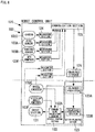
- FIG. 8 illustrates a second configuration example of the motion prediction control device according to the second embodiment of the present invention. In this drawing, only the robot control unit 120 is shown.
- the type of the sensors 103 is not limited. More specifically, for example, sensors such as a camera 103d, a GPS compass 103e, and a steering angle encoder 103f for measuring the steering angle of a wheel provided in the robot 101 may be added, as illustrated in FIG. 8 , or some of the sensors may not be used in the configuration.
- the remaining aspects of the second configuration example of the motion prediction control device may be the same as the first configuration example of the motion prediction control device.
- the action planning section 123 is a real-time processing system that operates at a fixed control cycle, and predicts the present or future position or posture of the self robot 101 by using an on-robot predictor 123a, the predicted position or posture being used to calculate a target trajectory of the robot 101 by a trajectory generating section 123b. Further, if necessary, the present or future position and posture of another robot 101 is predicted to, for example, avoid a collision.
- the on-robot predictor 123a carries out calculation for causing a state amount that is related to robot control and that is included in the internal state X recorded in the data storage unit 116, to proceed to specified time by using the state transition equation f(X).
- the on-robot predictor 123a is designed to be capable of performing prediction processing under the time limit of real-time control.
- the vehicle control section 122 is a real-time processing system operating at a predetermined control cycle, calculates a command value by a command value calculating section 122a, and controls the drive section 121 such that the robot 101 moves along a target trajectory.
- a communication section 125 has a function for data communication between the robot 101 (i.e., the robot control unit 120 provided in the robot 101) and the data storage unit 116. More specifically, a device adapted to perform wired communication such as Ethernet (registered trademark) or USB, or a device adapted to perform wireless communication such as Bluetooth or wireless LAN is used.
- wired communication such as Ethernet (registered trademark) or USB
- wireless communication such as Bluetooth or wireless LAN
- the data storage unit 116 holds data including the internal state X, the internal state model time tx, the observation value Y, the measurement time ty, the state transition equation f, the observation equation h, and the state estimation accuracy index value E.
- the measuring unit 112 or the measuring section 124 repeats the following steps (1) to (3) at an arbitrary timing.
- Accurately controlling the drive section 121 requires that the vehicle control section 122 calculate control command values at a fixed cycle. Further, the target trajectory referred to by the vehicle control section 122 must be generated beforehand by the action planning section 123. Hence, the processing by the action planning section 123 and the vehicle control section 122 is real-time processing repeated at a fixed cycle.
- the control cycle of the action planning section 123 is longer than the control cycle of the vehicle control section 122 (depending on the length of a target trajectory generated at a time).
- a target trajectory includes a general travel path to a target point in addition to an immediate travel path referred to by the vehicle control section 122.
- the processing by the action planning section 123 is further divided into two or more parts for generating a local path, generating a global path, and generating a more global path, for example.
- the processing for generating the local path will have a shorter control cycle.
- the processing may have a long control cycle or may be non-real-time processing with no constant cycle.
- FIG. 9 illustrates a third configuration example of the motion prediction control device according to the second embodiment of the present invention.
- the robot control unit 120 is further provided with an on-robot storage 126.
- the on-robot predictor 123a refers to the latest internal state X in the data storage unit 116. At this time, communication takes time, so that a prediction value may not be determined under a predetermined time limit. In this example, therefore, the contents of the data storage unit 116 are sequentially transferred to the on-robot storage 126, and the on-robot predictor 123a refers to the on-robot storage 126.
- the transfer timing is the moment the internal state X in the data storage unit 116 is updated (immediately after the step (6) described above).
- the second robot control unit 120B and the third robot control unit 120C also include the on-robot predictor 123a, the on-robot storage 126 and the like, as with the first robot control unit 120A.
- the number of the robot control units 120 is three in this example, the number may alternatively be two or four or more.
- the remaining aspects may be the same as the first configuration example or the second configuration example of the motion prediction control device.
- FIG. 10 illustrates a fourth configuration example of the motion prediction control unit according to the second embodiment of the present invention. This drawing illustrates only the robot control unit 120.
- the measuring unit 112 is used.
- the measuring unit 112 is provided in the robot control unit 120 (i.e., the robot 101) that does not include a travel mechanism, and handled as a type of the robot control unit 120.
- the system configuration in the second embodiment of the present invention includes two types, namely, the state estimation unit 114 and the robot control unit 120, and the robot control unit 120 (the robot 101) includes one that does not include a travel mechanism.
- the data storage unit 116 may be any memory as long as it is a shared memory from which the same data is read by a plurality of units or programs and to which the same data is written by a plurality of units or programs. This obviates the need to set the data storage unit 116 as an independent unit. Instead, the data storage unit 116 may be prepared in a memory space of the communication section 125 or the state estimation unit 114 or the like, as illustrated in FIG. 10 .
- state estimation unit 114 may be configured to be installed in one of the robots 101, and combined with the robot control unit 120 as illustrated in FIG. 10 .
- a plurality of programs can be concurrently run on a single personal computer as a state estimation program and a robot control program.
- the remaining aspects may be the same as the first configuration example, the second configuration example, or the third configuration example of the motion prediction control device.
- the prediction values calculated by the on-robot predictor 123a are used to control the robot 101.
- a person or an object around the robot 101 can be measured by the robot 101, and the information on the position or the motion of the person or the object around the robot 101 can be predicted by the on-robot predictor 123a so as to present the information to people, thus providing a service of presentation of changing information in real time.
- the measuring unit 112, the state estimation unit 114, and the data storage unit 116 acquire the sensor information of an object and/or the plurality of robots 101 at an arbitrary timing that is not dependent on the control cycle of the robots 101, predict the internal state X of each of the robots 101 of the same time as the time when the sensor information is acquired, compare the predicted internal state with the sensor information, update the internal state X, and store the updated internal state X and the state transition equation f(X) used for the prediction.
- a plurality of robot control units 120 predicts the prediction value required for each of the robots 101 on the basis of the latest internal state X stored in the data storage unit 116. This allows a control command value to be calculated at a control cycle determined for each of the robots 101 without being influenced by the calculation amount of a state estimation, thereby controlling a plurality of the robots 101.
- each of the robot control units 120 can operate without being subjected to the influence of time required for the update processing of the state estimation.
- each of the robot control units 120 independently carries out the prediction calculation, so that the time required for the prediction processing will not be increased. This obviates the need for reviewing the design of an arithmetic processing capability and the like when changing the system.
- the time limit of the prediction processing can be set for each of the robot control units 120.
- the accuracy of a prediction value to be calculated, the type of a prediction value, and the like can be also set for each of the robot control units 120.
- ingenuities such as changing the accuracy of the prediction calculation or calculating only a necessary variable in the internal state X, by taking into account the time required for the prediction processing, the control cycle and the like can be implemented in each of the robots 101.
- the data storage unit 116 transfers the latest internal state X stored in the data storage unit 116 to the on-robot storage 126 at a timing that does not depend on a request from the robot 101, thus permitting prompt reference to data required for the prediction processing in the case where the communication between the robot control unit 120 and the state estimation unit 114 takes time or in the case where the time required for the communication is not constant.
- the prediction processing can be completed within predetermined time although the data referred to on the robot is not necessarily the latest value due to the influence of a communication delay.
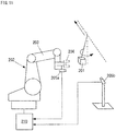
- FIG. 11 illustrates a configuration example of a robot system that includes a motion prediction control device according to a third embodiment of the present invention.
- the reference sign 201 denotes an object (workpiece)
- the reference sign 202 denotes a robot
- the reference sign 203 denotes a robot arm
- the reference sign 204 denotes a hand
- the reference sign 205a denotes a first camera secured to the hand 204
- the reference sign 205b denotes a second camera secured at an external fixed position
- the reference sign 210 denotes a motion prediction control device.
- the robot system is configured such that the workpiece 201 that moves while performing a pendular motion, is measured by the cameras 205a and 205b, and the robot 202 is controlled to follow the workpiece 201 to grasp the workpiece 201 by the hand 204.
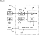
- FIG. 12 illustrates a configuration example of the motion prediction control device according to the third embodiment of the present invention.
- the motion prediction control device 210 includes a measuring unit 212, a state estimation unit 214, and a robot control unit 220.
- the state estimation unit 214 is provided with a data storage unit 216.
- the measuring unit 212 measures the position and the posture of the object 201.
- the measuring unit 212 in this example includes two measuring units (a first measuring unit 212a and a second measuring unit 212b) that are connected to the first camera 205a and the second camera 205b, respectively.
- two cameras and two measuring units are used to capture images of the object 201 through the first camera 205a and the second camera 205b, and the position and the posture of the object 201 are determined by image processing.
- the determined position and posture of the object 201 are stored in the data storage unit 216.
- the measuring unit 212 is not limited to this configuration, and may alternatively use a measuring unit, such as a laser radar, capable of performing, alone, three-dimensional measurement of the position of the object 201.
- a measuring unit such as a laser radar
- the state estimation unit 214 has functions to estimate (update) the internal state of the object 201, including an accuracy index value E (to be discussed hereinafter), on the basis of a state transition model and an observation model, from a measurement result of the measurement of the object 201, and to determine whether or not the object 201 can be grasped on the basis of the accuracy index value E.
- an accuracy index value E to be discussed hereinafter
- a state estimation algorithm based on the algorithm of a Kalman filter is installed in the state estimation unit 214 in this example.
- state variables are referred to as an internal state X, together.
- These state variables include a deflection angle ⁇ and an angular velocity ⁇ of the pendulum by which the workpiece 1 is suspended, and the positions of supporting points x, y and z of the pendulum.
- an accurate initial condition is not necessarily known. Therefore, the covariance C ov X 0 predicting the magnitude of the difference between the initial condition and an actual condition is defined.
- the state transition equation (1) indicates how the internal state X changes with time.
- the state transition equation is defined mainly on the basis of a motion equation of the pendulum and the uniform linear motion of the supporting point positions.
- the defined state transition equation (1) does not necessarily coincide with the actual motion of the object 201.
- the Kalman filter defines the "observation model” (an observation equation and an observation noise) of expressions (2) and (3), denoting the position and the posture of the object 201, which are calculated by the measuring unit 212, by a measurement value Y.
- observation equation (2) is an expression that associates the internal state X and the measurement value Y.
- observation noise (3) denotes a covariance that indicates the magnitude of a measurement error involved in the measurement at time t and that depends on the resolution and the direction of viewpoint of a camera.
- the observation noise (3) is not a fixed value, but the observation noise (3) is calculated by the measuring unit 212 for each image and handed together with a measurement value over to the state estimation unit 214.
- the robot control unit 220 has a function for predicting a destination of the object 201 on the basis of an estimation result (updating result) of the internal state and then controlling the robot 202 so as to perform a grasping motion in the case where the object 201 can be grasped.
- the robot control unit 220 receives, for example, the information on the position of the hand tip from the robot 202, and transmits a hand tip velocity command value and a hand opening/closing command value. Such transmission and reception is carried out at a predetermined control cycle (a 4-ms cycle).
- the position and the posture of the object 201 are measured as the sensor information by the measuring unit 212.
- the internal state of the object 201 including the accuracy index value E is estimated (updated) by the state estimation unit 214 on the basis of the state transition model, and at the step (C), whether the object 201 can be grasped or not is determined on the basis of the accuracy index value E.
- the robot control unit 220 predicts the destination of the object 201 on the basis of an estimation result of the internal state, and causes the robot 202 to perform a grasping motion.
- the robot control unit 220 causes the robot 202 to move such that the measurement of the position and the posture of the object 201 can be continued.
- the accuracy index value E includes the error between the prediction values of the predicted position and posture of the object 201 and the actual values thereof, and a covariance matrix that predicts the variance of the error on the basis of a state transition model and an observation model.
- step (C) mentioned above it is preferably determined that the object can be grasped if the square of a Mahalanobis distance M t obtained by dividing the error by the covariance matrix is smaller than a first threshold value, and the determinant of the covariance matrix is smaller than a second threshold value.
- the first threshold value and the second threshold value are preset arbitrary threshold values.
- step (c) mentioned above it may also be determined that the object can be grasped if the square of the Mahalanobis distance M t obtained by dividing the error by the covariance matrix is smaller than a third threshold value, and a trace of the covariance matrix is smaller than a fourth threshold value.
- the third threshold value and the fourth threshold value are preset arbitrary threshold values.
- the measuring unit 212 (the first measuring unit 212a and the second measuring unit 212b) transmits, at an arbitrary timing, a shutter signal to two cameras (the first camera 205a and the second camera 205b) to acquire a captured image.
- the measuring unit 212 acquires the information on the position and the posture of the object 201 (the measurement values Y) by carrying out image processing of the obtained image. For example, a white area in the image is extracted to determine the center of gravity.
- the time at which the shutter signal is transmitted from the measuring unit 212 is denoted by ty, and the observation noise C ov S t is calculated on the basis of the orientations, the resolutions, and the like of the cameras 205a and 205b.
- the state estimation unit 214 compares the measurement value Y and a prediction value Ym of Y predicted by the state transition model and the observation model so as to correct the internal state X.
- the accuracy index value E that indicates the accuracy for predicting the position of the object 201 is calculated.
- the internal state is updated at an arbitrary timing that is independent of the control cycle of the robot control unit 220.
- the robot control unit 220 refers to a result supplied by the state estimation unit 214 at each control cycle to assess the accuracy index value E, thereby determining whether or not to start the grasping motion.
- the grasping motion when the grasping motion is started, the future position of the object 201 is predicted, and a hand tip velocity command value is calculated to aim at the predicted grasp position. If the grasping motion is not performed, then the hand tip velocity command value is calculated so as to enable the cameras 205a and 205b to continue to capture the object 201.
- the details of the processing by the state estimation unit 214 in the process (a4) mentioned above will be given below.
- the processing details given below denote a general state estimation means that uses a Kalman filter.
- a state transition duration ⁇ t is calculated on the basis of the measurement time ty and the current model time t.
- the initial value of the model time t is the time at which the measurement is started.
- the measurement time may be defined as the elapsed time that uses the start time as the starting point, and the initial value of the model time may be set to zero.
- the internal state at measurement time ty is predicted.
- matrix A denotes the matrix obtained by partially differentiating the state transition equation f.
- t of the internal state before the update (b9) is represented by expression (5).
- t A t ⁇ t ⁇ C ov X t ⁇ A t ⁇ t T + Q ⁇ ⁇ t
- a t ( ⁇ t) of the state transition equation is represented by expression (6).
- a t ⁇ t ⁇ f X t ⁇ t / ⁇ X t
- a prediction value Ym t+ ⁇ t of the measurement value Y is predicted according to expression (7) by using an internal state prediction value and the observation equation.
- Ym t + ⁇ t g X t + ⁇ t
- a covariance C ov Y t+ ⁇ t of a prediction value Ym is determined according to expression (8) on the basis of the covariance of an internal state prediction value.
- Matrix H denotes a matrix obtained by partially differentiating an observation equation g.
- C ov Y t + ⁇ t H t ⁇ C ov X t + ⁇ t
- H t ⁇ g X t / ⁇ X t
- a covariance V t+ ⁇ t that takes into account the measurement error of a camera is determined according to expression (10).
- the covariance V t+ ⁇ t combines the covariance of the prediction value Ym and a camera observation noise, so that the covariance V t+ ⁇ t becomes a covariance that indicates the magnitude of the difference between the prediction value Ym and the observation value Y.
- V t + ⁇ t C ov Y t + ⁇ t + C ov S t + ⁇ t
- K t+ ⁇ t is calculated according to expression (11).
- K t + ⁇ t C ov X t + ⁇ t
- the internal state X t+ ⁇ t is updated according to expressions (12) and (13).
- the internal state before the update is denoted by X t+ ⁇ t
- the symbol Y denotes an observation value measured by a sensor.
- the processing of the steps (b1) to (b9) described above revises (i.e., updates) the internal state on the basis of the observation value at time ty.
- the update of the internal state is implemented at an arbitrary timing that is independent of the control cycle of the robot control unit 220.
- the internal state gradually approaches a true value (e.g., the actual velocity of an object) as the entire system repeats the processing of the processes (a1) to (a6) described above.
- a true value e.g., the actual velocity of an object
- the prediction value covariances C ov Y and V determined in the steps (b5) and (b6) mentioned above are assessed. These covariances indicate the magnitude of a prediction error in the case where the position and the posture of an object are predicted by using a current estimation result.
- the state estimation unit 214 therefore, calculates the accuracy index value E, which indicates the accuracy of the current state estimation, as shown below after the processing of the steps (b1) to (b9).
- the accuracy index value E is calculated according to any one of (c1), (c2) and (c3) given below.
- E exp ⁇ M t + ⁇ t 2 / 2 / 2 ⁇ m V t + ⁇ t 0.5 where the symbols m, Y, Ym, and eY are expressed by the same numbers of variables.
- E exp ⁇ M t + ⁇ t 2 / 2 / trace C ov Y t + ⁇ t 0.5 (c3): the total sum of E in expression (16) or (17) on all past measurement results, such as E obtained by expression (18), where p denotes the number of variables of the internal state.
- Expression (16) in (c1) is an expression for assessing the model suitability of a normal distribution, while expression (18) in (c3) denotes the information criterion (AIC).
- Expression (17) in (c2) is characterized by the use of the trace of the covariance C ov Y as the denominator.
- the square root of the determinant of covariances denotes the volume of the distribution of eY.
- the square root of the trace in expression (17) denotes the radius of a smallest sphere encompassing the distribution.
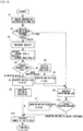
- FIG. 13 is an entire flowchart of a motion prediction control method according to the third embodiment of the present invention. As illustrated in the flowchart, the motion prediction control method includes steps (production processes) S1 to S12.
- the information on a hand tip position and the like is received from the robot 202.
- the robot 202 controls the communication of the robot 202 such that the communication is carried out at a control cycle of, for example, 4 ms.
- the robot control unit 220 is required to stand by until data is received, and complete the transmission processing of the step S12 within the control cycle of, for example, 4 ms once data is received.
- a flag F indicating that the grasping motion is being performed is determined.
- the flag F is initialized to "false" at the beginning of a program.
- the processing from the process (a1) to the process (a4) described above is carried out if the grasping motion is not being performed.
- This processing may be carried out by a different processing system at an arbitrary execution cycle, while the robot control unit 220 refers to the latest estimation result and the accuracy index value E.
- step S4 it is determined whether to perform the grasping motion or to continue a follow-up operation on the basis of the accuracy index value E of the current state estimation.
- the determination means one of the following means (d1) to (d3) is used.
- (d3) Although the latest measurement results are used to make determinations in both (d1) and (d2) described above, the determination may be made, considering the accuracy index values for a few past points. For example, as with (c3) described above, a method in which the logarithms of the accuracy index values calculated in the past are summed up, or a method in which the average value of the values for a predetermined past duration is used may be adopted.
- the grasping motion flag F is set as "false” if the grasping motion is not performed.
- arm velocities Vx, Vy and Vz are set according to, for example, expressions (19), (20) and (21) given below if the grasping motion is not performed.
- Vx Kpx ⁇ mx ⁇ rx + Kdx ⁇ mx ⁇ rx ⁇ pr _ x
- Vy Kpy ⁇ my ⁇ ry + Kdy ⁇ my ⁇ ry ⁇ pr _ y
- Vz Kpz ⁇ mz ⁇ rz + Kdz ⁇ mz ⁇ rz ⁇ pr _ z
- the control is PD control
- the symbols mx, my and mz denote a measured current position [mm] of the object
- the symbols rx, ry and rz denote the current position [mm] of a follow-up control point (a point on the sight line of a camera)
- the symbols pr_x, pr_y and pr_z denote positional differences (e.g., my - ry and mz - rz) calculated at a previous step
- the symbol Kp denotes a position control gain
- the symbol Kd denotes a differential control gain.
- the future position and posture of the object 201 are predicted by using the state transition model and the observation model, to determine a grasping position A.
- the grasping motion flag F is set as "true" at the beginning of the grasping motion.
- the target velocity of the robot arm 203 is calculated such that the robot arm 203 moves to the grasping position A.
- the grasping motion it is determined whether or not the grasping motion has been finished. For example, it is determined that the grasping motion has been finished if the robot arm 203 has reached the grasping position A, and the operation for closing the hand 204 has been finished.
- the grasping motion flag F is set as "false.” If the grasping motion is not to be terminated, then the grasping motion flag F remains "true,” so that the grasping motion will be continued from the next cycle, by following the branch point of the step S2.
- the calculated target velocity and the hand opening/closing command value are transmitted to the robot 202.
- the Kalman filter is used as the method for estimating the motion state of the object 201.
- a different technique may be used as long as it is a state estimation technique that satisfies the conditions described below.
- a particle filter, a least squares method, or the like may be applied.
- the covariance matrix expecting the variance of an error may be either V or C ov Y.
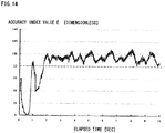
- FIG. 14 is a chart illustrating the relationship between the elapsed time and the accuracy index value E in the example.
- This example concerns the results of the calculation of the accuracy index value E according to expression (17) of (c2) described above.
- the chart indicates that the accuracy index value E gradually increases from a measurement start, and stabilizes at a value of 80 or more after the two seconds lapses from the measurement start.
- grasping failure can be minimized by establishing a grasping motion starting condition that the accuracy index value E in expression (17) is 80 or more.
- the accuracy index value temporarily increases in some cases. For this reason, the determination is preferably made on the basis of the accuracy index values for a few past points, as with (c3) described above.
- the determination is based on an average value of a few past points that exceeds 80, or an average value that continues to exceed 80 for a predetermined duration or longer.
- a condition that the accuracy index value continuously exceeds 80 for 120 ms or longer is preferably set as the condition for starting the grasping motion.
- the position or the posture of the object 201 is measured, and the internal state of the object 201 is estimated.
- the state estimation unit 214 estimates the internal state of the object 201 including the accuracy index value E, and determines from the accuracy index value E whether or not the object 201 can be grasped. Hence, if the object 201 cannot be grasped, then the robot control unit 220 moves the robot 202 such that, for example, the measurement of the position and the posture of the object 201 can be continued, thus preventing a grasping failure to occur in the case of a deteriorated prediction accuracy.
- the robot control unit 220 predicts the destination of the object 201 on the basis of an estimation result of the internal state, and causes the robot 202 to perform the grasping motion, thus enabling the robot 202 to follow and securely grasp the object 201.
- the object 201 is mobile, whereas the robot 202 is fixed.
- the third embodiment of the present invention is not limited to the above-mentioned examples, and includes a case where an object is immobile, whereas a robot is mobile or a case where both an object and a robot are mobile.
- the movement of an object in the third embodiment of the present invention means a relative movement of the object observed from a robot.
Landscapes
- Engineering & Computer Science (AREA)
- Robotics (AREA)
- Mechanical Engineering (AREA)
- Multimedia (AREA)
- Human Computer Interaction (AREA)
- Manipulator (AREA)
Claims (10)
- Bewegungsvorhersage-Steuervorrichtung (10, 110, 210), umfassend:eine Messeinheit (12, 112, 212), die Sensorinformationen von zahlreichen Robotern (2, 101, 202) durch Messen der zahlreichen Roboter (2, 101, 202) erfasst;eine Zustandsschätzeinheit (14, 114, 214), die interne Zustände der zahlreichen Roboter (2, 101, 202) auf der Basis der Sensorinformationen vorhersagt und aktualisiert;eine Datenspeichereinheit (16, 116, 216), die die von der Zustandsschätzeinheit (14, 114, 214) aktualisierten internen Zustände speichert; undzahlreiche Robotersteuereinheiten (20, 120, 220), die jeweils die zahlreichen Roboter (2, 101, 202) steuern,wobei die Messeinheit (12, 112, 212) die Sensorinformationen der zahlreichen Roboter (2, 101, 202) zu beliebigen Zeitpunkten erfasst, die unabhängig von Steuerzyklen der zahlreichen Roboter (2, 101, 202) sind;zu beliebigen Zeitpunkten, die unabhängig von Steuerzyklen der zahlreichen Roboter (2, 101, 202) sind, die Zustandsschätzeinheit (14, 114, 214) den internen Zustand jedes Roboters gleichzeitig mit dem Zeitpunkt vorhersagt, zu dem Sensorinformationen bezogen werden, und den vorhergesagten internen Zustand mit den Sensorinformationen jedes Roboters vergleicht, um die internen Zustände der zahlreichen Roboter (2, 101, 202) zu aktualisieren,die Datenspeichereinheit (16, 116, 216) zu Zeitpunkten, die unabhängig von Anforderungen aus den zahlreichen Robotern (2, 101, 202) sind, die neuesten internen Zustände, die in der Datenspeichereinheit (16, 116, 216) gespeichert sind, zu robotereigenen Speichern (26, 126) der zahlreichen Roboter (2, 101, 202) überträgt undjede der Robotersteuereinheiten (20, 120, 220) umfasst:den robotereigenen Speicher (26, 126), der den letzten internen Zustand speichert, der in der Datenspeichereinheit (16, 116, 216) gespeichert ist; undeinen robotereigenen Prädiktor (24, 123a), der in dem Steuerzyklus des entsprechenden Roboters (2, 101, 202) einen Vorhersagewert, der zur Steuerung des Roboters (2, 101, 202) erforderlich ist, auf der Basis des letzten internen Zustands vorhersagt, der in dem robotereigenen Speicher (26, 126) gespeichert ist.
- Bewegungsvorhersage-Steuervorrichtung (110) nach Anspruch 1,
bei der jede der Robotersteuereinheiten (120) einen Aktionsplanungsabschnitt (123) umfasst, der die folgenden Schritte wiederholt: Berechnen einer gegenwärtigen Position oder einer zukünftigen Position des eigenen Roboters (101) unter Verwendung des robotereigenen Prädiktors (123a); Berechnen einer gegenwärtigen Position oder einer zukünftigen Position eines anderen der zahlreichen Roboter (101); und Erzeugen einer Zieltrajektorie, um zu bewirken, dass sich der eigene Roboter (101) zu einer Zielposition bewegt. - Bewegungsvorhersage-Steuervorrichtung (10) nach Anspruch 1,
bei der die Datenspeichereinheit (16) bei der Aktualisierung den aktualisierten internen Zustand und die für die Vorhersage verwendete Zustandsübergangsgleichung speichert. - Bewegungsvorhersage-Steuervorrichtung (110) nach Anspruch 3, bei der die zahlreichen Robotersteuereinheiten (120) bei den Steuerzyklen der jeweiligen Roboter (101) Vorhersagewerte vorhersagen, die zum Steuern der jeweiligen Roboter (101) erforderlich sind um die zahlreichen Roboter (101) in Echtzeit zu steuern.
- Bewegungsvorhersage-Steuervorrichtung (110) nach Anspruch 3,
bei der die Zustandsschätzeinheit (114) einen gesamten Vorhersageabschnitt (115a), der den internen Zustand vorhersagt, und einen Aktualisierungsabschnitt (115c) umfasst, der den von dem gesamten Vorhersageabschnitt (115a) vorhergesagten internen Zustand aktualisiert. - Bewegungsvorhersage-Steuervorrichtung (10) nach Anspruch 3, bei der der interne Zustand eine Zustandsvariable ist, die die Position, die Stellung, die Geschwindigkeit oder die Winkelgeschwindigkeit des Roboters (2) angibt.
- Bewegungsvorhersage-Steuerverfahren, umfassend folgende Schritte:(A) Messen einer Vielzahl von Robotern (2, 101, 202) durch eine Messeinheit (12, 112, 212), um dadurch Sensorinformationen über zahlreiche Roboter (2, 101, 202) zu erhalten;(B) Vorhersagen interner Zustände der zahlreichen Roboter (2, 101, 202) auf der Basis der Sensorinformationen und Aktualisieren des internen Zustands durch eine Zustandsschätzeinheit (14, 114, 214);(C) Speichern der aktualisierten internen Zustände durch eine Datenspeichereinheit (16, 116, 216); und(D) Steuern jeweils der zahlreichen Roboter (2, 101, 202) durch zahlreiche Robotersteuereinheiten (20, 120, 220),
wobei bei Schritt (B) zu beliebigen Zeitpunkten, die unabhängig von Steuerzyklen der zahlreichen Roboter (2, 101, 202) sind, durch die Zustandsschätzeinheit (14, 114, 214) der interne Zustand jedes Roboters zu selben Zeit wie die Zeit, zu der die Sensorinformationen bezogen werden, vorhergesagt wird, und der vorhergesagte interne Zustand mit den Sensorinformationen jedes zu aktualisierenden Roboters verglichen wird,
wobei das Verfahren folgenden Schritt umfasst: (E) Übertragen der letzten internen Zustände, die in der Datenspeichereinheit (16, 116, 216) gespeichert sind, zu Zeitpunkten, die unabhängig von Anforderungen von den zahlreichen Robotern (2, 101, 202) sind, von der Datenspeichereinheit (16, 116, 216) zu robotereigenen Speichern (26, 126) der zahlreichen Roboter (2, 101, 202), die in den robotereigenen Speichern (26, 126) gespeichert werden sollen, und
in Schritt (D) ein Vorhersagewert, der zum Steuern des Roboters (2, 101, 202) erforderlich ist, durch einen robotereigenen Prädiktor (24, 123a) jedes der zahlreichen Robotersteuereinheiten (20, 120, 220) bei dem Steuerzyklus des entsprechenden Roboters (2, 101, 202) auf der Grundlage des letzten internen Zustands berechnet wird, der in dem Speicher des Roboters (26, 126) gespeichert ist. - Bewegungsvorhersage-Steuerverfahren nach Anspruch 7,
bei dem der Schritt (D) das Wiederholen folgender Schritte umfasst: Berechnen einer gegenwärtigen Position oder einer zukünftigen Position des eigenen Roboters (101) unter Verwendung des robotereigenen Prädiktors (123a); Berechnen einer gegenwärtigen Position oder einer zukünftigen Position eines anderen der zahlreichen Roboter (101); und Erzeugen einer Zieltrajektorie, um zu bewirken, dass sich der eigene Roboter (101) zu einer Zielposition bewegt. - Bewegungsvorhersage-Steuerverfahren nach Anspruch 7,
bei dem in Schritt (C) der aktualisierte interne Zustand und die für die Vorhersage verwendete Zustandsübergangsgleichung von der Datenspeichereinheit (16) gespeichert werden. - Bewegungsvorhersage-Steuerverfahren nach Anspruch 8 oder 9, bei dem der Steuerzyklus ein fester Zyklus ist, der kürzer als ein Verarbeitungsintervall der Messeinheit ist.
Applications Claiming Priority (4)
| Application Number | Priority Date | Filing Date | Title |
|---|---|---|---|
| JP2011106822A JP5733516B2 (ja) | 2011-05-12 | 2011-05-12 | 移動体把持装置と方法 |
| JP2011116663A JP5733518B2 (ja) | 2011-05-25 | 2011-05-25 | 運動予測制御装置と方法 |
| JP2011116883A JP5679121B2 (ja) | 2011-05-25 | 2011-05-25 | ロボットの運動予測制御方法と装置 |
| PCT/JP2012/060918 WO2012153629A1 (ja) | 2011-05-12 | 2012-04-24 | 運動予測制御装置と方法 |
Publications (3)
| Publication Number | Publication Date |
|---|---|
| EP2708334A1 EP2708334A1 (de) | 2014-03-19 |
| EP2708334A4 EP2708334A4 (de) | 2015-07-01 |
| EP2708334B1 true EP2708334B1 (de) | 2020-05-06 |
Family
ID=47139115
Family Applications (1)
| Application Number | Title | Priority Date | Filing Date |
|---|---|---|---|
| EP12782445.6A Active EP2708334B1 (de) | 2011-05-12 | 2012-04-24 | Vorrichtung und verfahren zur steuerung der vorhersage von bewegungen |
Country Status (4)
| Country | Link |
|---|---|
| US (1) | US9108321B2 (de) |
| EP (1) | EP2708334B1 (de) |
| CN (1) | CN103517789B (de) |
| WO (1) | WO2012153629A1 (de) |
Cited By (1)
| Publication number | Priority date | Publication date | Assignee | Title |
|---|---|---|---|---|
| DE102021114598B4 (de) | 2020-12-04 | 2023-03-30 | GM Global Technology Operations LLC | Verfahren zum Durchführen einer Herstellungsoperation sowie Herstellungssystem zur Durchfürung des Verfahrens |
Families Citing this family (37)
| Publication number | Priority date | Publication date | Assignee | Title |
|---|---|---|---|---|
| JP2013022705A (ja) * | 2011-07-25 | 2013-02-04 | Sony Corp | ロボット装置及びロボット装置の制御方法、コンピューター・プログラム、並びにロボット・システム |
| CN104959982A (zh) * | 2013-10-10 | 2015-10-07 | 精工爱普生株式会社 | 机器人控制系统、机器人、程序以及机器人控制方法 |
| CN103895017B (zh) * | 2014-03-14 | 2015-09-09 | 北京邮电大学 | 一种基于使用可靠度的空间机械臂控制方法及系统 |
| JP6364836B2 (ja) * | 2014-03-14 | 2018-08-01 | セイコーエプソン株式会社 | ロボット、ロボットシステム、及び制御装置 |
| CN103991074B (zh) * | 2014-05-21 | 2015-10-21 | 北京邮电大学 | 一种基于粒子滤波算法的空间机械臂控制方法及系统 |
| US10265848B2 (en) * | 2014-07-08 | 2019-04-23 | Beihang University | Robotic hybrid system application framework based on multi-core processor architecture |
| US9597801B2 (en) * | 2014-10-21 | 2017-03-21 | Centurylink Intellectual Property Llc | Automated data center |
| US9889566B2 (en) * | 2015-05-01 | 2018-02-13 | General Electric Company | Systems and methods for control of robotic manipulation |
| US10059004B2 (en) * | 2015-06-22 | 2018-08-28 | Ricoh Company, Ltd. | Robot, information processing system, and storage medium |
| US10195740B2 (en) * | 2015-09-10 | 2019-02-05 | X Development Llc | Using object observations of mobile robots to generate a spatio-temporal object inventory, and using the inventory to determine monitoring parameters for the mobile robots |
| JP6077617B1 (ja) * | 2015-09-25 | 2017-02-08 | ファナック株式会社 | 最適な速度分布を生成する工作機械 |
| JP6711591B2 (ja) * | 2015-11-06 | 2020-06-17 | キヤノン株式会社 | ロボット制御装置およびロボット制御方法 |
| JP6409206B2 (ja) * | 2016-03-28 | 2018-10-24 | Groove X株式会社 | お出迎え行動する自律行動型ロボット |
| JP6544878B2 (ja) * | 2016-05-16 | 2019-07-17 | 本田技研工業株式会社 | 車両制御システム、車両制御方法、および車両制御プログラム |
| JP6444940B2 (ja) * | 2016-05-17 | 2018-12-26 | ファナック株式会社 | 被加工物保持システム |
| JP6514156B2 (ja) * | 2016-08-17 | 2019-05-15 | ファナック株式会社 | ロボット制御装置 |
| CN109690619A (zh) * | 2016-09-13 | 2019-04-26 | 株式会社日立信息通信工程 | 状态预测装置以及状态预测方法 |
| JP2018126796A (ja) * | 2017-02-06 | 2018-08-16 | セイコーエプソン株式会社 | 制御装置、ロボットおよびロボットシステム |
| DE102017005194C5 (de) * | 2017-05-31 | 2022-05-19 | Kuka Deutschland Gmbh | Steuern einer Roboteranordnung |
| DE102017115833A1 (de) * | 2017-07-13 | 2019-01-17 | SW Automation GmbH | Verfahren zum Betreiben einer Werkstück-Bearbeitungs-Anlage und Werkstück-Bearbeitungs-Anlage |
| JP6963748B2 (ja) * | 2017-11-24 | 2021-11-10 | 株式会社安川電機 | ロボットシステム及びロボットシステムの制御方法 |
| US11453123B2 (en) * | 2017-12-27 | 2022-09-27 | Stmicroelectronics, Inc. | Robotic device with time-of-flight proximity sensing system |
| WO2019146201A1 (ja) * | 2018-01-23 | 2019-08-01 | ソニー株式会社 | 情報処理装置、情報処理方法及び情報処理システム |
| SG11202010344QA (en) | 2018-06-22 | 2020-11-27 | Soft Servo Systems Inc | Motion control program, motion control method, and motion control device |
| CN112236728B (zh) * | 2018-06-22 | 2024-05-03 | 软件伺服系统公司 | 运动控制程序、运动控制方法以及运动控制装置 |
| EP3812855B1 (de) | 2018-06-22 | 2024-01-17 | Soft Servo Systems, Inc. | Bewegungssteuerungsprogramm, bewegungssteuerungsverfahren und bewegungssteuerungsvorrichtung |
| CN110733034B (zh) * | 2018-07-20 | 2022-10-21 | 台达电子工业股份有限公司 | 机械手臂校正方法、机械手臂校正系统以及输送系统 |
| JP6878391B2 (ja) | 2018-12-18 | 2021-05-26 | ファナック株式会社 | ロボットシステムとその調整方法 |
| JP7178931B2 (ja) * | 2019-03-11 | 2022-11-28 | 本田技研工業株式会社 | センサ配置態様の取得装置 |
| JP7207207B2 (ja) * | 2019-07-09 | 2023-01-18 | トヨタ自動車株式会社 | 演算装置、機械学習方法及び制御プログラム |
| CN110355788B (zh) * | 2019-07-24 | 2024-05-14 | 哈尔滨工业大学(深圳) | 移动操作机器人大尺度空间高精度在线标定系统 |
| JP7358994B2 (ja) * | 2020-01-08 | 2023-10-11 | オムロン株式会社 | ロボット制御装置、ロボット制御システム、ロボット制御方法及びロボット制御プログラム |
| US20230032982A1 (en) | 2020-01-22 | 2023-02-02 | Abb Schweiz Ag | System and method for operating the robot, electronic device and computer readable medium |
| JP7416197B2 (ja) * | 2020-02-25 | 2024-01-17 | 日本電気株式会社 | 制御装置、制御方法及びプログラム |
| CN111360829B (zh) * | 2020-03-13 | 2023-12-05 | 苏州三百亿科技有限公司 | 人工智能大数据下医疗用品运送机器人及其控制方法 |
| CN113954075A (zh) * | 2021-11-10 | 2022-01-21 | 佛山市南海区广工大数控装备协同创新研究院 | 基于机器人主动运动的运动物体跟踪抓取方法和装置 |
| CN117182928B (zh) * | 2023-11-03 | 2024-01-26 | 深圳市磐锋精密技术有限公司 | 一种智能抓取机器手同步控制系统 |
Family Cites Families (21)
| Publication number | Priority date | Publication date | Assignee | Title |
|---|---|---|---|---|
| JPH0719818A (ja) * | 1993-06-30 | 1995-01-20 | Kajima Corp | 3次元運動予測装置 |
| JPH1124718A (ja) * | 1997-07-07 | 1999-01-29 | Toshiba Corp | ロボットの制御装置及び制御方法 |
| JP3988255B2 (ja) * | 1998-05-20 | 2007-10-10 | 株式会社安川電機 | 数値制御装置における位置指令方法および装置 |
| JP4153625B2 (ja) | 1999-08-19 | 2008-09-24 | 株式会社トキメック | 運動予測装置 |
| JP4265088B2 (ja) | 2000-07-10 | 2009-05-20 | 株式会社豊田中央研究所 | ロボット装置及びその制御方法 |
| JP4072017B2 (ja) * | 2002-08-02 | 2008-04-02 | 日本放送協会 | 状態推定装置、その方法及びそのプログラム、並びに、現在状態推定装置及び未来状態推定装置 |
| EP1841570A1 (de) * | 2005-01-26 | 2007-10-10 | Abb Ab | Vorrichtung und verfahren zur kalibrierung des mittelpunkts von einem auf einem roboter angebrachtem werkzeug mithilfe einer kamera |
| JP4504228B2 (ja) * | 2005-03-01 | 2010-07-14 | 川崎重工業株式会社 | ロボットの制御装置および制御方法 |
| JP2007090448A (ja) * | 2005-09-27 | 2007-04-12 | Honda Motor Co Ltd | 二次元コード検出装置及びそのプログラム、並びに、ロボット制御情報生成装置及びロボット |
| ES2452022T3 (es) * | 2006-02-06 | 2014-03-31 | Abb Research Ltd. | Sistema de línea de prensas y método |
| JP2007316966A (ja) * | 2006-05-26 | 2007-12-06 | Fujitsu Ltd | 移動ロボット、その制御方法及びプログラム |
| US8676379B2 (en) * | 2006-07-04 | 2014-03-18 | Panasonic Corporation | Device and method for controlling robot arm, robot, and robot arm control program |
| JP4836872B2 (ja) * | 2007-05-31 | 2011-12-14 | 株式会社東芝 | 制御装置、制御方法、プログラム及びロボット |
| CN101216711A (zh) * | 2008-01-08 | 2008-07-09 | 哈尔滨工程大学 | 两栖机械螃蟹的分级控制装置及控制方法 |
| WO2010134603A1 (ja) * | 2009-05-22 | 2010-11-25 | 関東自動車工業株式会社 | 作業支援ロボットシステム |
| CN101920498A (zh) * | 2009-06-16 | 2010-12-22 | 泰怡凯电器(苏州)有限公司 | 实现室内服务机器人同时定位和地图创建的装置及机器人 |
| CN101630413B (zh) * | 2009-08-14 | 2012-01-25 | 浙江大学 | 一种多机器人跟踪移动目标方法 |
| KR101633362B1 (ko) * | 2010-01-18 | 2016-06-28 | 삼성전자 주식회사 | 인간형 로봇 및 그 보행 제어방법 |
| JP4850956B2 (ja) * | 2010-02-19 | 2012-01-11 | ファナック株式会社 | 学習制御機能を備えたロボット |
| JP2011209203A (ja) * | 2010-03-30 | 2011-10-20 | Sony Corp | 自己位置推定装置および自己位置推定方法 |
| CN101943916B (zh) * | 2010-09-07 | 2012-09-26 | 陕西科技大学 | 一种基于卡尔曼滤波器预测的机器人避障方法 |
-
2012
- 2012-04-24 WO PCT/JP2012/060918 patent/WO2012153629A1/ja active Application Filing
- 2012-04-24 EP EP12782445.6A patent/EP2708334B1/de active Active
- 2012-04-24 CN CN201280022935.9A patent/CN103517789B/zh active Active
-
2013
- 2013-11-12 US US14/078,342 patent/US9108321B2/en active Active
Non-Patent Citations (1)
| Title |
|---|
| None * |
Cited By (1)
| Publication number | Priority date | Publication date | Assignee | Title |
|---|---|---|---|---|
| DE102021114598B4 (de) | 2020-12-04 | 2023-03-30 | GM Global Technology Operations LLC | Verfahren zum Durchführen einer Herstellungsoperation sowie Herstellungssystem zur Durchfürung des Verfahrens |
Also Published As
| Publication number | Publication date |
|---|---|
| US9108321B2 (en) | 2015-08-18 |
| US20140074291A1 (en) | 2014-03-13 |
| EP2708334A4 (de) | 2015-07-01 |
| WO2012153629A1 (ja) | 2012-11-15 |
| EP2708334A1 (de) | 2014-03-19 |
| CN103517789B (zh) | 2015-11-25 |
| CN103517789A (zh) | 2014-01-15 |
Similar Documents
| Publication | Publication Date | Title |
|---|---|---|
| EP2708334B1 (de) | Vorrichtung und verfahren zur steuerung der vorhersage von bewegungen | |
| CA3107374C (en) | Systems and methods for autonomous machine tracking and localization of mobile objects | |
| KR100561855B1 (ko) | 로봇용 로컬라이제이션 시스템 | |
| US8793069B2 (en) | Object recognition system for autonomous mobile body | |
| EP1978432B1 (de) | Routingvorrichtung für eine autonome mobile Einheit | |
| CN102269994B (zh) | 无人搬送车以及行驶控制方法 | |
| CN112203812B (zh) | 机器人系统及追加学习方法 | |
| JP2012245568A (ja) | 運動予測制御装置と方法 | |
| JP4746349B2 (ja) | ロボット行動選択装置及びロボット行動選択方法 | |
| US20190113603A1 (en) | Method for predicting a motion of an object | |
| JP5679121B2 (ja) | ロボットの運動予測制御方法と装置 | |
| JP2022543926A (ja) | ロボットシステムのためのデリバティブフリーモデル学習のシステムおよび設計 | |
| JP5169273B2 (ja) | 移動ロボットの制御装置および移動ロボットシステム | |
| JP5733516B2 (ja) | 移動体把持装置と方法 | |
| Du et al. | A novel human–manipulators interface using hybrid sensors with Kalman filter and particle filter | |
| JP6035671B2 (ja) | デバイスの状態同定方法と装置 | |
| US20210200205A1 (en) | Moving control method, moving control device, moving control system, program, and storage medium for multi-vehicle | |
| CN111045428A (zh) | 避障方法、移动机器人及计算机可读存储介质 | |
| CN113984045B (zh) | 水下机器人移动式对接目标运动状态估计方法及系统 | |
| Faria et al. | Implementation of an autonomous ROS-based mobile robot with AI depth estimation | |
| WO2018006298A1 (zh) | 一种利用平衡车载物的方法和平衡车 | |
| CN114415655A (zh) | 一种基于改进slam的巡检机器人导航控制方法 | |
| CN114791284B (zh) | 机器人之中电子罗盘的标定方法、装置及机器人 | |
| CN112415990B (zh) | 作业设备的控制方法及装置、作业设备 | |
| CN117207190B (zh) | 基于视觉与触觉融合的精准抓取机器人系统 |
Legal Events
| Date | Code | Title | Description |
|---|---|---|---|
| PUAI | Public reference made under article 153(3) epc to a published international application that has entered the european phase |
Free format text: ORIGINAL CODE: 0009012 |
|
| 17P | Request for examination filed |
Effective date: 20131112 |
|
| AK | Designated contracting states |
Kind code of ref document: A1 Designated state(s): AL AT BE BG CH CY CZ DE DK EE ES FI FR GB GR HR HU IE IS IT LI LT LU LV MC MK MT NL NO PL PT RO RS SE SI SK SM TR |
|
| DAX | Request for extension of the european patent (deleted) | ||
| RA4 | Supplementary search report drawn up and despatched (corrected) |
Effective date: 20150529 |
|
| RIC1 | Information provided on ipc code assigned before grant |
Ipc: B25J 13/08 20060101ALI20150522BHEP Ipc: B25J 13/00 20060101AFI20150522BHEP Ipc: B25J 9/16 20060101ALI20150522BHEP |
|
| STAA | Information on the status of an ep patent application or granted ep patent |
Free format text: STATUS: EXAMINATION IS IN PROGRESS |
|
| 17Q | First examination report despatched |
Effective date: 20180628 |
|
| REG | Reference to a national code |
Ref country code: DE Ref legal event code: R079 Ref document number: 602012069932 Country of ref document: DE Free format text: PREVIOUS MAIN CLASS: B25J0013000000 Ipc: B25J0009160000 |
|
| RIC1 | Information provided on ipc code assigned before grant |
Ipc: B25J 19/02 20060101ALI20191121BHEP Ipc: B25J 9/16 20060101AFI20191121BHEP Ipc: B25J 5/00 20060101ALI20191121BHEP |
|
| GRAP | Despatch of communication of intention to grant a patent |
Free format text: ORIGINAL CODE: EPIDOSNIGR1 |
|
| STAA | Information on the status of an ep patent application or granted ep patent |
Free format text: STATUS: GRANT OF PATENT IS INTENDED |
|
| INTG | Intention to grant announced |
Effective date: 20200107 |
|
| RIN1 | Information on inventor provided before grant (corrected) |
Inventor name: SONEHARA, MITSUHARU Inventor name: FUJII, MASAKAZU Inventor name: BANNO, HAJIME Inventor name: EMOTO, SHUHEI Inventor name: HAYASHI, TOSHIHIRO |
|
| GRAS | Grant fee paid |
Free format text: ORIGINAL CODE: EPIDOSNIGR3 |
|
| GRAA | (expected) grant |
Free format text: ORIGINAL CODE: 0009210 |
|
| STAA | Information on the status of an ep patent application or granted ep patent |
Free format text: STATUS: THE PATENT HAS BEEN GRANTED |
|
| AK | Designated contracting states |
Kind code of ref document: B1 Designated state(s): AL AT BE BG CH CY CZ DE DK EE ES FI FR GB GR HR HU IE IS IT LI LT LU LV MC MK MT NL NO PL PT RO RS SE SI SK SM TR |
|
| REG | Reference to a national code |
Ref country code: GB Ref legal event code: FG4D |
|
| REG | Reference to a national code |
Ref country code: CH Ref legal event code: EP Ref country code: AT Ref legal event code: REF Ref document number: 1266033 Country of ref document: AT Kind code of ref document: T Effective date: 20200515 |
|
| REG | Reference to a national code |
Ref country code: IE Ref legal event code: FG4D |
|
| REG | Reference to a national code |
Ref country code: DE Ref legal event code: R096 Ref document number: 602012069932 Country of ref document: DE |
|
| REG | Reference to a national code |
Ref country code: LT Ref legal event code: MG4D |
|
| REG | Reference to a national code |
Ref country code: NL Ref legal event code: MP Effective date: 20200506 |
|
| PG25 | Lapsed in a contracting state [announced via postgrant information from national office to epo] |
Ref country code: SE Free format text: LAPSE BECAUSE OF FAILURE TO SUBMIT A TRANSLATION OF THE DESCRIPTION OR TO PAY THE FEE WITHIN THE PRESCRIBED TIME-LIMIT Effective date: 20200506 Ref country code: GR Free format text: LAPSE BECAUSE OF FAILURE TO SUBMIT A TRANSLATION OF THE DESCRIPTION OR TO PAY THE FEE WITHIN THE PRESCRIBED TIME-LIMIT Effective date: 20200807 Ref country code: FI Free format text: LAPSE BECAUSE OF FAILURE TO SUBMIT A TRANSLATION OF THE DESCRIPTION OR TO PAY THE FEE WITHIN THE PRESCRIBED TIME-LIMIT Effective date: 20200506 Ref country code: NO Free format text: LAPSE BECAUSE OF FAILURE TO SUBMIT A TRANSLATION OF THE DESCRIPTION OR TO PAY THE FEE WITHIN THE PRESCRIBED TIME-LIMIT Effective date: 20200806 Ref country code: IS Free format text: LAPSE BECAUSE OF FAILURE TO SUBMIT A TRANSLATION OF THE DESCRIPTION OR TO PAY THE FEE WITHIN THE PRESCRIBED TIME-LIMIT Effective date: 20200906 Ref country code: PT Free format text: LAPSE BECAUSE OF FAILURE TO SUBMIT A TRANSLATION OF THE DESCRIPTION OR TO PAY THE FEE WITHIN THE PRESCRIBED TIME-LIMIT Effective date: 20200907 Ref country code: LT Free format text: LAPSE BECAUSE OF FAILURE TO SUBMIT A TRANSLATION OF THE DESCRIPTION OR TO PAY THE FEE WITHIN THE PRESCRIBED TIME-LIMIT Effective date: 20200506 |
|
| PG25 | Lapsed in a contracting state [announced via postgrant information from national office to epo] |
Ref country code: RS Free format text: LAPSE BECAUSE OF FAILURE TO SUBMIT A TRANSLATION OF THE DESCRIPTION OR TO PAY THE FEE WITHIN THE PRESCRIBED TIME-LIMIT Effective date: 20200506 Ref country code: HR Free format text: LAPSE BECAUSE OF FAILURE TO SUBMIT A TRANSLATION OF THE DESCRIPTION OR TO PAY THE FEE WITHIN THE PRESCRIBED TIME-LIMIT Effective date: 20200506 Ref country code: LV Free format text: LAPSE BECAUSE OF FAILURE TO SUBMIT A TRANSLATION OF THE DESCRIPTION OR TO PAY THE FEE WITHIN THE PRESCRIBED TIME-LIMIT Effective date: 20200506 Ref country code: BG Free format text: LAPSE BECAUSE OF FAILURE TO SUBMIT A TRANSLATION OF THE DESCRIPTION OR TO PAY THE FEE WITHIN THE PRESCRIBED TIME-LIMIT Effective date: 20200806 |
|
| REG | Reference to a national code |
Ref country code: AT Ref legal event code: MK05 Ref document number: 1266033 Country of ref document: AT Kind code of ref document: T Effective date: 20200506 |
|
| PG25 | Lapsed in a contracting state [announced via postgrant information from national office to epo] |
Ref country code: NL Free format text: LAPSE BECAUSE OF FAILURE TO SUBMIT A TRANSLATION OF THE DESCRIPTION OR TO PAY THE FEE WITHIN THE PRESCRIBED TIME-LIMIT Effective date: 20200506 Ref country code: AL Free format text: LAPSE BECAUSE OF FAILURE TO SUBMIT A TRANSLATION OF THE DESCRIPTION OR TO PAY THE FEE WITHIN THE PRESCRIBED TIME-LIMIT Effective date: 20200506 |
|
| PG25 | Lapsed in a contracting state [announced via postgrant information from national office to epo] |
Ref country code: RO Free format text: LAPSE BECAUSE OF FAILURE TO SUBMIT A TRANSLATION OF THE DESCRIPTION OR TO PAY THE FEE WITHIN THE PRESCRIBED TIME-LIMIT Effective date: 20200506 Ref country code: IT Free format text: LAPSE BECAUSE OF FAILURE TO SUBMIT A TRANSLATION OF THE DESCRIPTION OR TO PAY THE FEE WITHIN THE PRESCRIBED TIME-LIMIT Effective date: 20200506 Ref country code: SM Free format text: LAPSE BECAUSE OF FAILURE TO SUBMIT A TRANSLATION OF THE DESCRIPTION OR TO PAY THE FEE WITHIN THE PRESCRIBED TIME-LIMIT Effective date: 20200506 Ref country code: DK Free format text: LAPSE BECAUSE OF FAILURE TO SUBMIT A TRANSLATION OF THE DESCRIPTION OR TO PAY THE FEE WITHIN THE PRESCRIBED TIME-LIMIT Effective date: 20200506 Ref country code: EE Free format text: LAPSE BECAUSE OF FAILURE TO SUBMIT A TRANSLATION OF THE DESCRIPTION OR TO PAY THE FEE WITHIN THE PRESCRIBED TIME-LIMIT Effective date: 20200506 Ref country code: AT Free format text: LAPSE BECAUSE OF FAILURE TO SUBMIT A TRANSLATION OF THE DESCRIPTION OR TO PAY THE FEE WITHIN THE PRESCRIBED TIME-LIMIT Effective date: 20200506 Ref country code: ES Free format text: LAPSE BECAUSE OF FAILURE TO SUBMIT A TRANSLATION OF THE DESCRIPTION OR TO PAY THE FEE WITHIN THE PRESCRIBED TIME-LIMIT Effective date: 20200506 Ref country code: CZ Free format text: LAPSE BECAUSE OF FAILURE TO SUBMIT A TRANSLATION OF THE DESCRIPTION OR TO PAY THE FEE WITHIN THE PRESCRIBED TIME-LIMIT Effective date: 20200506 |
|
| REG | Reference to a national code |
Ref country code: DE Ref legal event code: R097 Ref document number: 602012069932 Country of ref document: DE |
|
| PG25 | Lapsed in a contracting state [announced via postgrant information from national office to epo] |
Ref country code: SK Free format text: LAPSE BECAUSE OF FAILURE TO SUBMIT A TRANSLATION OF THE DESCRIPTION OR TO PAY THE FEE WITHIN THE PRESCRIBED TIME-LIMIT Effective date: 20200506 Ref country code: PL Free format text: LAPSE BECAUSE OF FAILURE TO SUBMIT A TRANSLATION OF THE DESCRIPTION OR TO PAY THE FEE WITHIN THE PRESCRIBED TIME-LIMIT Effective date: 20200506 |
|
| PLBE | No opposition filed within time limit |
Free format text: ORIGINAL CODE: 0009261 |
|
| STAA | Information on the status of an ep patent application or granted ep patent |
Free format text: STATUS: NO OPPOSITION FILED WITHIN TIME LIMIT |
|
| 26N | No opposition filed |
Effective date: 20210209 |
|
| PG25 | Lapsed in a contracting state [announced via postgrant information from national office to epo] |
Ref country code: SI Free format text: LAPSE BECAUSE OF FAILURE TO SUBMIT A TRANSLATION OF THE DESCRIPTION OR TO PAY THE FEE WITHIN THE PRESCRIBED TIME-LIMIT Effective date: 20200506 |
|
| PG25 | Lapsed in a contracting state [announced via postgrant information from national office to epo] |
Ref country code: MC Free format text: LAPSE BECAUSE OF FAILURE TO SUBMIT A TRANSLATION OF THE DESCRIPTION OR TO PAY THE FEE WITHIN THE PRESCRIBED TIME-LIMIT Effective date: 20200506 |
|
| PG25 | Lapsed in a contracting state [announced via postgrant information from national office to epo] |
Ref country code: LU Free format text: LAPSE BECAUSE OF NON-PAYMENT OF DUE FEES Effective date: 20210424 |
|
| REG | Reference to a national code |
Ref country code: BE Ref legal event code: MM Effective date: 20210430 |
|
| PG25 | Lapsed in a contracting state [announced via postgrant information from national office to epo] |
Ref country code: CH Free format text: LAPSE BECAUSE OF NON-PAYMENT OF DUE FEES Effective date: 20210430 Ref country code: FR Free format text: LAPSE BECAUSE OF NON-PAYMENT OF DUE FEES Effective date: 20210430 Ref country code: LI Free format text: LAPSE BECAUSE OF NON-PAYMENT OF DUE FEES Effective date: 20210430 |
|
| PG25 | Lapsed in a contracting state [announced via postgrant information from national office to epo] |
Ref country code: IE Free format text: LAPSE BECAUSE OF NON-PAYMENT OF DUE FEES Effective date: 20210424 |
|
| PG25 | Lapsed in a contracting state [announced via postgrant information from national office to epo] |
Ref country code: BE Free format text: LAPSE BECAUSE OF NON-PAYMENT OF DUE FEES Effective date: 20210430 |
|
| PG25 | Lapsed in a contracting state [announced via postgrant information from national office to epo] |
Ref country code: HU Free format text: LAPSE BECAUSE OF FAILURE TO SUBMIT A TRANSLATION OF THE DESCRIPTION OR TO PAY THE FEE WITHIN THE PRESCRIBED TIME-LIMIT; INVALID AB INITIO Effective date: 20120424 Ref country code: CY Free format text: LAPSE BECAUSE OF FAILURE TO SUBMIT A TRANSLATION OF THE DESCRIPTION OR TO PAY THE FEE WITHIN THE PRESCRIBED TIME-LIMIT Effective date: 20200506 |
|
| PG25 | Lapsed in a contracting state [announced via postgrant information from national office to epo] |
Ref country code: MK Free format text: LAPSE BECAUSE OF FAILURE TO SUBMIT A TRANSLATION OF THE DESCRIPTION OR TO PAY THE FEE WITHIN THE PRESCRIBED TIME-LIMIT Effective date: 20200506 |
|
| PGFP | Annual fee paid to national office [announced via postgrant information from national office to epo] |
Ref country code: GB Payment date: 20240320 Year of fee payment: 13 |
|
| PGFP | Annual fee paid to national office [announced via postgrant information from national office to epo] |
Ref country code: DE Payment date: 20240320 Year of fee payment: 13 |