WO2019146201A1 - 情報処理装置、情報処理方法及び情報処理システム - Google Patents
情報処理装置、情報処理方法及び情報処理システム Download PDFInfo
- Publication number
- WO2019146201A1 WO2019146201A1 PCT/JP2018/040276 JP2018040276W WO2019146201A1 WO 2019146201 A1 WO2019146201 A1 WO 2019146201A1 JP 2018040276 W JP2018040276 W JP 2018040276W WO 2019146201 A1 WO2019146201 A1 WO 2019146201A1
- Authority
- WO
- WIPO (PCT)
- Prior art keywords
- marker
- information
- visual sensor
- camera
- movable
- Prior art date
Links
- 230000010365 information processing Effects 0.000 title claims abstract description 44
- 238000003672 processing method Methods 0.000 title claims description 5
- 239000003550 marker Substances 0.000 claims abstract description 223
- 230000000007 visual effect Effects 0.000 claims abstract description 92
- 238000004364 calculation method Methods 0.000 claims abstract description 42
- 239000012636 effector Substances 0.000 claims description 21
- 230000010354 integration Effects 0.000 claims description 10
- 238000012545 processing Methods 0.000 abstract description 19
- 230000006870 function Effects 0.000 description 27
- 238000005259 measurement Methods 0.000 description 26
- 238000000034 method Methods 0.000 description 23
- 238000003384 imaging method Methods 0.000 description 14
- 210000003128 head Anatomy 0.000 description 13
- 239000011159 matrix material Substances 0.000 description 11
- 230000008569 process Effects 0.000 description 10
- 238000005516 engineering process Methods 0.000 description 7
- 238000006243 chemical reaction Methods 0.000 description 6
- 210000000744 eyelid Anatomy 0.000 description 6
- 238000005452 bending Methods 0.000 description 5
- 238000004891 communication Methods 0.000 description 5
- 230000000694 effects Effects 0.000 description 5
- 238000001514 detection method Methods 0.000 description 4
- 230000009466 transformation Effects 0.000 description 4
- 238000004458 analytical method Methods 0.000 description 2
- 238000010586 diagram Methods 0.000 description 2
- 238000010191 image analysis Methods 0.000 description 2
- 230000001151 other effect Effects 0.000 description 2
- 240000004050 Pentaglottis sempervirens Species 0.000 description 1
- 235000004522 Pentaglottis sempervirens Nutrition 0.000 description 1
- 230000001133 acceleration Effects 0.000 description 1
- 230000009471 action Effects 0.000 description 1
- 230000004075 alteration Effects 0.000 description 1
- 230000008859 change Effects 0.000 description 1
- 238000010411 cooking Methods 0.000 description 1
- 238000009434 installation Methods 0.000 description 1
- 230000007246 mechanism Effects 0.000 description 1
- 238000012986 modification Methods 0.000 description 1
- 230000004048 modification Effects 0.000 description 1
- 238000003825 pressing Methods 0.000 description 1
Images


Classifications
-
- B—PERFORMING OPERATIONS; TRANSPORTING
- B25—HAND TOOLS; PORTABLE POWER-DRIVEN TOOLS; MANIPULATORS
- B25J—MANIPULATORS; CHAMBERS PROVIDED WITH MANIPULATION DEVICES
- B25J9/00—Programme-controlled manipulators
- B25J9/16—Programme controls
- B25J9/1694—Programme controls characterised by use of sensors other than normal servo-feedback from position, speed or acceleration sensors, perception control, multi-sensor controlled systems, sensor fusion
- B25J9/1697—Vision controlled systems
-
- B—PERFORMING OPERATIONS; TRANSPORTING
- B25—HAND TOOLS; PORTABLE POWER-DRIVEN TOOLS; MANIPULATORS
- B25J—MANIPULATORS; CHAMBERS PROVIDED WITH MANIPULATION DEVICES
- B25J13/00—Controls for manipulators
- B25J13/02—Hand grip control means
-
- B—PERFORMING OPERATIONS; TRANSPORTING
- B25—HAND TOOLS; PORTABLE POWER-DRIVEN TOOLS; MANIPULATORS
- B25J—MANIPULATORS; CHAMBERS PROVIDED WITH MANIPULATION DEVICES
- B25J13/00—Controls for manipulators
- B25J13/08—Controls for manipulators by means of sensing devices, e.g. viewing or touching devices
- B25J13/088—Controls for manipulators by means of sensing devices, e.g. viewing or touching devices with position, velocity or acceleration sensors
- B25J13/089—Determining the position of the robot with reference to its environment
-
- B—PERFORMING OPERATIONS; TRANSPORTING
- B25—HAND TOOLS; PORTABLE POWER-DRIVEN TOOLS; MANIPULATORS
- B25J—MANIPULATORS; CHAMBERS PROVIDED WITH MANIPULATION DEVICES
- B25J19/00—Accessories fitted to manipulators, e.g. for monitoring, for viewing; Safety devices combined with or specially adapted for use in connection with manipulators
- B25J19/02—Sensing devices
- B25J19/04—Viewing devices
-
- B—PERFORMING OPERATIONS; TRANSPORTING
- B25—HAND TOOLS; PORTABLE POWER-DRIVEN TOOLS; MANIPULATORS
- B25J—MANIPULATORS; CHAMBERS PROVIDED WITH MANIPULATION DEVICES
- B25J9/00—Programme-controlled manipulators
- B25J9/16—Programme controls
- B25J9/1612—Programme controls characterised by the hand, wrist, grip control
-
- B—PERFORMING OPERATIONS; TRANSPORTING
- B25—HAND TOOLS; PORTABLE POWER-DRIVEN TOOLS; MANIPULATORS
- B25J—MANIPULATORS; CHAMBERS PROVIDED WITH MANIPULATION DEVICES
- B25J9/00—Programme-controlled manipulators
- B25J9/16—Programme controls
- B25J9/1656—Programme controls characterised by programming, planning systems for manipulators
- B25J9/1669—Programme controls characterised by programming, planning systems for manipulators characterised by special application, e.g. multi-arm co-operation, assembly, grasping
-
- G—PHYSICS
- G01—MEASURING; TESTING
- G01B—MEASURING LENGTH, THICKNESS OR SIMILAR LINEAR DIMENSIONS; MEASURING ANGLES; MEASURING AREAS; MEASURING IRREGULARITIES OF SURFACES OR CONTOURS
- G01B11/00—Measuring arrangements characterised by the use of optical techniques
-
- G—PHYSICS
- G05—CONTROLLING; REGULATING
- G05D—SYSTEMS FOR CONTROLLING OR REGULATING NON-ELECTRIC VARIABLES
- G05D1/00—Control of position, course, altitude or attitude of land, water, air or space vehicles, e.g. using automatic pilots
- G05D1/02—Control of position or course in two dimensions
- G05D1/021—Control of position or course in two dimensions specially adapted to land vehicles
- G05D1/0231—Control of position or course in two dimensions specially adapted to land vehicles using optical position detecting means
- G05D1/0234—Control of position or course in two dimensions specially adapted to land vehicles using optical position detecting means using optical markers or beacons
-
- G—PHYSICS
- G06—COMPUTING; CALCULATING OR COUNTING
- G06T—IMAGE DATA PROCESSING OR GENERATION, IN GENERAL
- G06T7/00—Image analysis
- G06T7/70—Determining position or orientation of objects or cameras
-
- G—PHYSICS
- G05—CONTROLLING; REGULATING
- G05B—CONTROL OR REGULATING SYSTEMS IN GENERAL; FUNCTIONAL ELEMENTS OF SUCH SYSTEMS; MONITORING OR TESTING ARRANGEMENTS FOR SUCH SYSTEMS OR ELEMENTS
- G05B2219/00—Program-control systems
- G05B2219/30—Nc systems
- G05B2219/31—From computer integrated manufacturing till monitoring
- G05B2219/31048—Project on workpiece, image of finished workpiece, info or a spot
-
- G—PHYSICS
- G05—CONTROLLING; REGULATING
- G05B—CONTROL OR REGULATING SYSTEMS IN GENERAL; FUNCTIONAL ELEMENTS OF SUCH SYSTEMS; MONITORING OR TESTING ARRANGEMENTS FOR SUCH SYSTEMS OR ELEMENTS
- G05B2219/00—Program-control systems
- G05B2219/30—Nc systems
- G05B2219/37—Measurements
- G05B2219/37131—Moire pattern, diffraction grating, fringe
-
- G—PHYSICS
- G05—CONTROLLING; REGULATING
- G05B—CONTROL OR REGULATING SYSTEMS IN GENERAL; FUNCTIONAL ELEMENTS OF SUCH SYSTEMS; MONITORING OR TESTING ARRANGEMENTS FOR SUCH SYSTEMS OR ELEMENTS
- G05B2219/00—Program-control systems
- G05B2219/30—Nc systems
- G05B2219/39—Robotics, robotics to robotics hand
- G05B2219/39039—Two cameras detect same reference on workpiece to define its position in space
-
- G—PHYSICS
- G05—CONTROLLING; REGULATING
- G05B—CONTROL OR REGULATING SYSTEMS IN GENERAL; FUNCTIONAL ELEMENTS OF SUCH SYSTEMS; MONITORING OR TESTING ARRANGEMENTS FOR SUCH SYSTEMS OR ELEMENTS
- G05B2219/00—Program-control systems
- G05B2219/30—Nc systems
- G05B2219/39—Robotics, robotics to robotics hand
- G05B2219/39045—Camera on end effector detects reference pattern
-
- G—PHYSICS
- G05—CONTROLLING; REGULATING
- G05B—CONTROL OR REGULATING SYSTEMS IN GENERAL; FUNCTIONAL ELEMENTS OF SUCH SYSTEMS; MONITORING OR TESTING ARRANGEMENTS FOR SUCH SYSTEMS OR ELEMENTS
- G05B2219/00—Program-control systems
- G05B2219/30—Nc systems
- G05B2219/39—Robotics, robotics to robotics hand
- G05B2219/39393—Camera detects projected image, compare with reference image, position end effector
-
- G—PHYSICS
- G05—CONTROLLING; REGULATING
- G05B—CONTROL OR REGULATING SYSTEMS IN GENERAL; FUNCTIONAL ELEMENTS OF SUCH SYSTEMS; MONITORING OR TESTING ARRANGEMENTS FOR SUCH SYSTEMS OR ELEMENTS
- G05B2219/00—Program-control systems
- G05B2219/30—Nc systems
- G05B2219/39—Robotics, robotics to robotics hand
- G05B2219/39484—Locate, reach and grasp, visual guided grasping
-
- G—PHYSICS
- G05—CONTROLLING; REGULATING
- G05B—CONTROL OR REGULATING SYSTEMS IN GENERAL; FUNCTIONAL ELEMENTS OF SUCH SYSTEMS; MONITORING OR TESTING ARRANGEMENTS FOR SUCH SYSTEMS OR ELEMENTS
- G05B2219/00—Program-control systems
- G05B2219/30—Nc systems
- G05B2219/40—Robotics, robotics mapping to robotics vision
- G05B2219/40604—Two camera, global vision camera, end effector neighbourhood vision camera
-
- G—PHYSICS
- G05—CONTROLLING; REGULATING
- G05B—CONTROL OR REGULATING SYSTEMS IN GENERAL; FUNCTIONAL ELEMENTS OF SUCH SYSTEMS; MONITORING OR TESTING ARRANGEMENTS FOR SUCH SYSTEMS OR ELEMENTS
- G05B2219/00—Program-control systems
- G05B2219/30—Nc systems
- G05B2219/40—Robotics, robotics mapping to robotics vision
- G05B2219/40609—Camera to monitor end effector as well as object to be handled
-
- Y—GENERAL TAGGING OF NEW TECHNOLOGICAL DEVELOPMENTS; GENERAL TAGGING OF CROSS-SECTIONAL TECHNOLOGIES SPANNING OVER SEVERAL SECTIONS OF THE IPC; TECHNICAL SUBJECTS COVERED BY FORMER USPC CROSS-REFERENCE ART COLLECTIONS [XRACs] AND DIGESTS
- Y02—TECHNOLOGIES OR APPLICATIONS FOR MITIGATION OR ADAPTATION AGAINST CLIMATE CHANGE
- Y02P—CLIMATE CHANGE MITIGATION TECHNOLOGIES IN THE PRODUCTION OR PROCESSING OF GOODS
- Y02P90/00—Enabling technologies with a potential contribution to greenhouse gas [GHG] emissions mitigation
- Y02P90/02—Total factory control, e.g. smart factories, flexible manufacturing systems [FMS] or integrated manufacturing systems [IMS]
Definitions
- the present disclosure relates to an information processing apparatus, an information processing method, and an information processing system.
- the first position information acquired by reading the projected marker by the first visual sensor, and the second visual sensor moving relative to the first visual sensor are the marker
- An information processing apparatus including: a position calculation unit that calculates the position of the movable unit on which the second visual sensor is disposed, based on second position information including position information acquired by reading .
- the first position information acquired by reading the projected marker by the first visual sensor, and the second visual sensor moving relative to the first visual sensor are provided.
- An information processing method is provided, which calculates the position of a movable portion on which the second visual sensor is disposed, based on second position information including position information acquired by reading the marker.
- the first position information acquired by reading the projected marker by the first visual sensor, and the second visual sensor moving relative to the first visual sensor are provided.
- a position calculation unit that calculates a spatial position of a movable portion on which the second visual sensor is disposed, based on second position information including position information acquired by reading the marker;
- An information processing system is provided that includes a projection unit to project and the movable unit on which the second visual sensor is disposed and movable.
- position information of the first visual sensor and the second visual sensor based on the marker can be grasped.
- the position of the movable part provided with the second visual sensor can be calculated.
- Embodiment 1.1 Technical outline and external configuration 1.2. Internal configuration 1.3. Flow of processing 2. Modified example
- FIG. 1 is a view showing a robot 1 to which an information processing system according to an embodiment of the present disclosure is applied.
- the robot 1 may be a machine (device) capable of controlling the movement of the movable unit 11 using an electrical and / or magnetic action.
- the robot 1 is a humanoid self-supporting control robot, a quadruped walking robot, an autonomous vehicle, a drone, an industrial robot (for example, an assembly robot such as a machine), a service robot (for example, a medical robot such as a surgical robot)
- the robot may be a cooking robot or the like, or a toy, and is not limited to such an example.
- the outline of the technology and the external configuration will be described by taking an example in which the robot 1 grips the object H1 by focusing on an example in which the robot 1 is a humanoid autonomous control robot.
- the position of the tip of the movable portion where the robot 1 grips the object is It can be applied when calculating correctly.
- the robot 1 can grip the object at the target gripping position more accurately.
- the calculation load at the time of position calculation can be reduced by calculating the position of the tip of the movable part by reading the projected marker using various sensors provided to the robot 1 by the robot 1.
- the target gripping position for gripping the object is given by the user or the autonomous function of the robot 1 and refers to a position that is appropriate as the position of the tip of the movable part when the robot 1 grips the object. .
- the robot 1 includes, as various sensors, a first visual sensor, a second visual sensor, and a projection surface shape sensor, and an example in which they are imaging devices will be described.
- the first visual sensor will be referred to as a bird's-eye camera
- the second visual sensor will be referred to as a hand camera, and the external configuration of the robot 1 will be described.
- the robot (moving body) 1 is a robot including a head 10, a movable unit 11, a body unit 12, and a moving unit 13.
- the head 10 is connected to the torso 12 via a neck 102.
- the neck portion 102 may be rotatable around a predetermined rotation axis with respect to the body portion 12.
- the head 10 may be rotatable relative to the neck 102 or may be fixed to the neck 102.
- the head 10 is provided with the eyelid camera 101 that reads the marker M1.
- the movable portion 11 may be coupled to the body portion 12.
- the movable portion 11 holds the object H1 by moving.
- the movable portion 11 may be provided on one side of the body portion 12 of the robot 1 or may be provided on both sides. Also, a plurality of movable parts 11 may be provided for the robot 1.
- the movable portion 11 can be configured, for example, in a serial link structure. As shown in FIG. 1, the movable portion 11 may have at least one joint 111 between the connection portion of the body portion 12 and the movable portion 11 and the end effector 113. With such a structure of the movable portion 11, the movable portion 11 can have a plurality of degrees of freedom.
- the joint 111 is provided with an actuator for driving the joint 111 and an encoder for detecting the angular position of the joint 111.
- the movable unit 11 includes an end effector 113 at the tip of the movable unit 11.
- the end effector 113 may be configured to be able to grip the object H1.
- the end effector 113 may have a plurality of finger portions, and may hold the object H1 by bending the finger portions, and has a pair of plate-like end effectors 113 as shown in FIG.
- the object H1 may be gripped by narrowing the distance between the plates.
- the hand camera 112 can be disposed. Similar to the overhead camera 101, the hand camera 112 has a function of reading the marker M1.
- the position at which the hand camera 112 is disposed is in the vicinity of the end effector 113 or the end effector 113 provided at the tip of the movable portion 11.
- the present invention is not limited to this example, and the calculation place of the position of the movable unit is not limited to the tip of the movable unit.
- the position at which the hand camera 112 is provided may be provided at a position where it is desired to calculate the position in the movable portion 11.
- a hand camera 112 is provided in the vicinity of an end effector 113 that holds the object H1 in order to hold the object H1 accurately.
- a mechanical error or a deflection of the movable portion 11 with respect to the angle or position of the joint 111 generated when the movable portion 11 moves.
- Position calculation of the end effector 113 is possible. Therefore, more accurate position calculation can be performed.
- the body portion 12 is coupled to the head 10, the movable portion 11, and the moving portion 13.
- the body portion 12 is provided with a projector 121, and the projector 121 has a function of projecting the marker M1.
- a projection surface shape measurement sensor 122 is provided in the body portion 12 so that the shape of the surface on which the marker M1 is projected can be measured. Referring to FIG. 1, for example, the projection surface shape measurement sensor 122 measures the surface shape of the table 80 on which the marker M1 is projected.
- the moving unit 13 is connected to the body 12 and has a function of supporting the head 10, the movable unit 11 and the body 12 described above.
- the moving unit 13 may have, for example, a plurality of wheels 131 as illustrated in FIG. 1.
- the present invention is not limited to such an example, and the moving unit 13 may have a plurality of legs (for example, 2 legs or 4 legs) for walking, or an endless track such as Caterpillar (registered trademark). It may have a mechanism.
- the robot 1 reads the marker M1 projected by the projector 121 by the overhead camera 101 and the hand camera 112 using the configuration as described above, thereby determining the position of the tip of the movable portion 11 where the hand camera 112 is provided.
- the object H1 can be gripped accurately at a target gripping position which has been calculated with high accuracy and which is designated in advance.
- the calculation load for the calculation can be reduced because the method of calculating via the marker M1 is used.
- the shape and the like of the object and the movable portion are acquired by a camera and a camera capable of looking over the entire object
- a method of calculating the position of the tip of the movable portion by collating or image analyzing the shape data of the object may be considered.
- the computational load on image analysis is higher than the computational load on the technology of the present disclosure.
- the robot 1 since the position of the tip of the movable unit 11 can be calculated via the marker M1, it is not necessary to have shape data of the object H1 in advance. Therefore, even if the object H1 is an unknown object, the robot 1 can correctly grip the object H1.
- the position of the marker M1, the position of the object H1, the position of the overhead camera 101, and the position of the distal camera 112 are grasped using the overhead camera 101 and the distal end camera 112, and the positional relationship between them is grasped. Be done. Then, once their positional relationship is grasped, the robot 1 can move the movable portion 11 using only the information acquired by the hand camera 112 to grip the object H1. As a result, the robot 1 does not have to use the overhead camera 101 continuously, so the operation load of the robot 1 can be suppressed.
- the overhead camera 101, the projector 121, and the projection surface shape measurement sensor 122 are provided on the head 10 and the body 12 of the robot 1, respectively.
- the present invention is not limited to this example, and the overhead camera 101 need not necessarily be provided to the robot 1 and can capture the marker M1 and the hand camera 112, and can be installed anywhere as long as the position of the overhead camera 101 is clear. May be As described above, when each component is provided in a place other than the robot 1, the robot 1 may operate as an information processing system.
- the overhead camera 101, the projector 121, and the projection surface shape measurement sensor 122 may be installed on a ceiling or the like in a predetermined space where the projected marker M1 and the movable portion 11 can be viewed.
- the installation surface of the projection surface shape measurement sensor 122 and the projector 121 is not limited, the positional relationship between the projection surface shape measurement sensor 122 and the projector 121 needs to be known. If the relative positional relationship is known, each of the projection surface shape measurement sensor 122 and the projector 121 may be provided in the robot 1 or may be provided in a place other than the robot 1.
- FIG. 2 is a block diagram showing an internal configuration of the robot 1.
- the head 10 is provided with an eyelid camera 101 and an actuator 109.
- the actuator 109 has a function of performing mechanical movement when the robot 1 moves the head 10.
- the overhead camera 101 reads the projected marker M1 to obtain information on the marker M1, and the control unit 14 processes the information on the marker M1.
- the robot 1 has a function of acquiring the first position information.
- the overhead camera 101 will be described in detail below.
- the overhead camera 101 has a function of reading the projected marker M1 and outputting marker information to the control unit 14.
- the control unit 14 processes the marker information read by the overhead camera 101 to acquire the first position information.
- the first position information may be information including the positional relationship between the marker M1 in the space and the overhead camera 101 or posture information.
- the first positional relationship may be information indicating the position at which the overhead camera 101 is disposed with reference to the position of the marker M1, and is information indicating the distance or direction from the marker M1 to the overhead camera 101 It is also good.
- the first position information may include three-dimensional spatial coordinates of the overhead camera 101 based on the marker M1 in space. Also, the first position information may be indicated, for example, in coordinates (x, y, z).
- the first posture information may be, for example, information of the rotation angle of the first visual sensor with respect to the marker, and the camera 101 is rotated to the extent of the X axis, Y axis, and Z axis of the three-dimensional space. It may include information on the rotation angle (for example, roll angle, pitch angle, yaw angle) indicating whether it is present. Also, the first attitude information may be indicated by a rotation matrix or quaternion.
- the overhead camera 101 is an imaging device for reading the marker M1.
- the robot 1 can acquire the first position information by processing the captured image obtained by the imaging device by the control unit 14.
- the overhead camera 101 may capture a plurality of marker M1 images in order to read the marker M1.
- the overhead camera 101 may be an RGB camera or a thermo camera, and may capture an image (a still image or a moving image), and may have a lens system, a drive system, and an imaging element.
- the control unit 14 processes the captured image obtained by the overhead camera 101 to obtain the first position information.
- the position information of the hand camera may be acquired by the control unit 14 when the overhead camera 101 captures the hand camera 112 in addition to the projected marker M1.
- the overhead camera 101 captures the position of the object H1 and the position of the marker M1 as well as the hand camera 112.
- the position information of the hand camera 112 is acquired by the eyelid camera 101, so that the position of the hand camera 112 relative to the eye camera 101, the position of the object H1, The position of the marker M1 can be grasped.
- the control unit 14 can grasp the position information, positional relationship or posture information of the object H 1, the marker M 1, the overhead camera 101 and the hand camera 112 based on the overhead camera 101 by the method described above.
- the positional relationship indicates the position, distance, or direction of each of the object H1, the marker M1, the overhead camera 101, and the hand camera 112 which can be placed in a predetermined space, and the posture information indicates posture information on each rotation angle. obtain.
- the target gripping position for gripping the object H1 is specified in advance by the user or the autonomous function of the robot 1 with the overhead camera 101 as a reference.
- the first target grip position based on the overhead camera 101 can be converted into the second target grip position based on the hand camera 112 using the position information, the positional relationship, or the posture information. Details regarding conversion of the target gripping position will be described later.
- the movable unit 11 is controlled by the movable control unit 147.
- the movable unit 11 includes an end effector 113, a hand camera 112, and an actuator 119.
- the actuator 119 has a function of performing mechanical movement when the robot 1 moves the movable unit 11.
- the end effector 113 is provided at the tip of the movable portion 11 as described in the section of the external configuration, and has a function of gripping an object.
- the manual camera 112 will be described in detail.
- the hand camera 112 is provided on the movable unit 11, has a function of reading the marker M1 and outputting marker information to the control unit 14.
- the control unit 14 processes the marker information read by the hand camera 112 to acquire the second position information.
- the second position information may be information including positional relationship or posture information between the marker M1 and the hand camera 112 in the space.
- the second positional relationship may indicate the position at which the end camera 112 is disposed with reference to the position of the marker M1, and may be information indicating the distance or direction from the marker M1 to the end camera 112.
- the second position information may include three-dimensional space coordinates of the hand camera 112 based on the marker M1 in the space.
- the second position information may be indicated, for example, in the coordinates (x, y, z).
- the second posture information may be, for example, information on the rotation angle of the second visual sensor with respect to the marker, and the degree to which the hand camera 112 rotates about the X axis, Y axis, and Z axis of the three-dimensional space It may include information on the rotation angle (for example, roll angle, pitch angle, yaw angle) indicating whether it is present.
- the second attitude information may be indicated by a rotation matrix or quaternion.
- the second position information may include position information of the hand camera 112.
- the position information of the hand camera 112 may indicate the position at which the hand camera 112 is disposed with reference to the eyelid camera 101, and is information indicating the distance or direction from the eye camera 101 to the hand camera 112. Good.
- the second position information may include three-dimensional spatial coordinates of the hand camera 112 relative to the overhead camera 101 in the space. Also, the second position information may be indicated, for example, in the coordinates (x, y, z).
- the hand camera 112 is an imaging device, like the overhead camera 101, for reading the marker M1.
- the second position information may be acquired by processing the captured image obtained by the imaging device by the control unit 14. Similar to the overhead camera 101, the hand camera 112 may capture a plurality of marker M1 images in order to read the marker M1.
- the hand camera 112 may be an RGB camera or a thermo camera, and may capture an image (still image or moving image), and has a lens system, a drive system, and an imaging device. obtain.
- the second position information may be acquired by the control unit 14 performing image processing on a captured image obtained by the camera of the hand camera 112.
- the body portion 12 includes a projection surface shape measurement sensor 122, a projector 121, and an actuator 129.
- the actuator 129 has a function of causing the robot 1 to mechanically move the main body 12.
- the projector 121 and the projection surface shape measurement sensor 122 will be described below.
- the projection surface shape measurement sensor 122 has a function of measuring the shape of the surface on which the marker M1 is projected.
- the shape of the projection surface may be any curved surface such as a plane or a spherical surface, and the projection surface shape measurement sensor 122 acquires shape information of the projection surface.
- the shape information of the projection plane includes information on the uneven state or texture on the projection plane.
- the projection surface shape measurement sensor 122 may be an imaging device such as a camera.
- the projection surface shape measurement sensor 122 may be an imaging device for capturing an image (still image or moving image) such as an RGB camera or a thermo camera, and may have a lens system, a drive system, and an imaging element. Good.
- the projection surface shape measurement sensor 122 may analyze the captured image obtained by the camera to grasp the shape of the surface on which the marker M1 is projected.
- the projection surface shape measurement sensor 122 may include a sensor such as a depth sensor that acquires depth information in a space.
- the depth sensor includes an infrared distance measuring device, an ultrasonic distance measuring device, LiDAR (Laser Imaging Detection and Ranging), a stereo camera or the like to obtain depth information of the projection surface and the shape of the surface on which the marker M1 is projected. You may grasp
- the projection surface shape measurement sensor 122 may acquire depth information of the projection surface using a ToF (Time of Flight) method.
- ToF Time of Flight
- the projector 121 has a function of projecting the marker M1.
- the projector 121 may be, for example, a fixed wide-angle projector, or may be a so-called moving projector capable of changing the projection direction.
- the moving unit 13 has a function of moving as a support when the robot 1 moves.
- the moving unit 13 includes a sensor 132 and an actuator 139.
- the actuator 139 has a function of performing mechanical movement when the robot 1 moves the moving unit 13.
- the sensor 132 performs various types of sensing on the moving unit 13.
- the sensors 132 may include, for example, acceleration sensors, gyroscopes, temperature sensors, torque sensors, weight sensors, cameras, and / or microphones and the like.
- the moving unit 13 may determine the moving direction or position, and the like.
- Control unit 14 Next, the control unit 14 that controls various configurations of the main robot 1 when the robot 1 grips the object H1 will be described in detail.
- the control unit 14 has a function of performing general control on each configuration provided in the head 10, the movable unit 11, the body unit 12, and the moving unit 13. In the following, each configuration included in the control unit 14 will be described.
- the projection marker control unit 143 has a function of controlling the marker M1 projected by the projector 121.
- the control of the marker M1 includes functions of creating the marker M1 and changing the projection position of the marker M1.
- the projection marker control unit 143 creates the marker M1.
- the projection marker control unit 143 may create a marker M1 having a symbol or texture pattern such that an image feature such as a point, line or plane structure can be detected. Not limited to such an example, a marker M1 of any shape may be created.
- the control unit 14 can calculate the position of the tip of the movable unit 11 using various markers, and the convenience of the robot 1 is improved.
- the marker M1 may include visible light, infrared light, and ultraviolet light, and may emit light detectable by the overhead camera 101 and the hand camera 112.
- the projection marker control unit 143 can cause the storage unit 15 to store, as reference marker information, marker information such as what kind of image features the marker M1 having an image feature has been created and from which position it has been projected.
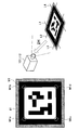
- the marker M1 will be further described with reference to FIG. In FIG. 3, an example of the projected marker M1 will be described.
- the table 80 is installed in a predetermined space, and the object H ⁇ b> 1 is disposed on the table 80.
- a marker M1 is projected near the object H1.
- the projection marker control unit 143 may create a plurality of markers M1 and project the plurality of markers M1.
- the projection marker control unit 143 projects the plurality of markers M1 so that the overhead camera 101 and the hand camera 112 are not shielded, even when a part of the markers M1 is affected by the shielding or the like.
- the marker M1 can be read by imaging the marker M1.
- an AR marker is shown as an example of the marker M1.
- the marker M1 has a square shape and has a predetermined length of horizontal length a and vertical length b. The lengths a and b of one side have the same length.
- the marker M1 has a white area surrounded by a black frame, and a point, a line, a plane structure or the like may be drawn in the white area.
- the projection marker control unit 143 may have a function of controlling the projection position of the marker M1.
- the projection position of the marker M1 is not limited as long as the projection surface shape can be measured. For example, when the robot 1 grips the object H1, the position of the tip of the movable unit 11 is calculated by reading the marker M1. Therefore, as the marker M1 is closer to the object H1, the bending of the movable unit 11 with respect to the target gripping position Machine error including can be suppressed. Thus, the marker M1 may be projected to the vicinity of the object H1 or may be projected to the object H1.
- the projection marker control unit 143 may change and control the projection location of the marker M1 in accordance with the visual range of the overhead camera 101 and the hand camera 112. For example, when the projected marker M1 is out of the visual range where the overhead camera 101 and the hand camera 112 can sense, the projection marker control unit 143 sets the marker to the visual range where the overhead camera 101 and the hand camera 112 can sense. The projection position of M1 may be changed.
- the projection position of the marker M1 can be changed in accordance with the situation of the robot 1 and the environment around the robot 1, and the convenience can be improved.
- the surrounding environment may be, for example, the environment of the projection plane when projecting an AR marker.
- the projection marker control unit 143 may project the AR marker to a place where the illuminance is low.
- the position calculation unit 141 uses the marker information acquired in advance using the overhead camera 101 and the hand camera 112 based on the shape information acquired using the projection surface shape measurement sensor 122, and the reference marker information and the like. It has a function of calculating the positions of the overhead camera 101 and the hand camera 112 by collating.
- the reference marker information is information on the marker M1 stored in the storage unit 15 when the projection marker control unit 143 creates and projects the marker M1.
- the reference marker M1 information includes information on the vertical and horizontal length of the marker M1, the outline of the marker M1, the point drawn on the white region of the marker M1, the line or the planar structure.
- the position calculation unit 141 is projected from a certain position according to the position at which the marker M1 is imaged by using the shape information acquired using the projection surface shape measurement sensor 122, the position of the projector, and the reference marker information. It is possible to estimate in advance what kind of captured image will be obtained by capturing an image of the marker M1 from an arbitrary position.
- the position of the overhead camera 101 and the hand camera 112 is calculated by collating this pre-estimated image with the image actually captured by the overhead camera 101 and the hand camera 112.
- the position calculation unit 141 collates the marker M1 with reference marker information will be described with reference to FIGS. 4 and 5.
- the marker M1 may be a symbol or texture pattern that facilitates detection of image features such as points, lines, and planar structures in a white area surrounded by a black frame.
- the position calculation unit 141 detects an image feature such as a point, a line, or a plane structure from information acquired using the overhead camera 101 and the hand camera 112, and detects the three-dimensional space coordinates of the real world and the two-dimensional image
- positional information, positional relationship or posture information of the overhead camera 101 and the hand camera 112 With respect to the marker M1.
- posture information which is information related to the rotation angles of the overhead camera 101 and the hand camera 112 with respect to positional information including space coordinates or a marker.
- FIG. 4 shows an example of the marker M1 projected on the plane 81.
- the position calculation unit 141 From the shape information acquired using the projection surface shape measurement sensor 122, the position calculation unit 141 first recognizes that the place where the marker M1 is projected is a plane. The position calculation unit 141 detects a planar structure in a square point, a line or a white area of the marker M1, on the premise that the marker M1 is projected on the same plane. The detection result and the reference marker information are collated to calculate the positions of the overhead camera 101 and the hand camera 112. The position where the projector 121 is arranged at this time is known. As a result, since the position calculation unit 141 knows which direction the projector 121 is projecting the marker M 1 from, it is possible to calculate the position based on the direction or position of the projector 121 by the above matching. .
- the position is calculated by, for example, detecting outlines L1, L2, L3 and L4 surrounding the marker M1, and then extracting four square corners M1a, M1b, M1c and M1d from their intersection points. After that, a surface is generated by extending each side in the projection direction of the overhead camera 101 and the hand camera 112, and the surface normal is calculated. Points and lines of the white area of the marker M1 obtained here, normal information of the surface and plane including the plane structure, points and lines of the white area of the reference marker information and normal information of the plane and plane including the plane structure Are compared with each other to estimate from where the overhead camera 101 and the hand camera 112 capture the marker M1, and the positions of the overhead camera 101 and the hand camera 112 are calculated.
- FIG. 5 shows an example of the marker M1 projected on the cylinder 82.
- the position calculation unit 141 From the shape information acquired using the projection surface shape measurement sensor 122, the position calculation unit 141 first recognizes that the location where the marker M1 is projected is a cylinder having a spherical surface. The position calculation unit 141 pre-estimates distortion generated in the marker M1, such as what shape the marker projected on the cylinder 82 has. The position calculation unit 141 detects a planar structure in a square point, a line, or a white area of the marker M1 on the assumption that the marker M1 is thus projected on a cylinder and taking into consideration the distortion estimated in advance. The detection result and the reference marker information are collated to calculate the positions of the overhead camera 101 and the hand camera 112.
- the four corners of the square M1a, M1b, M1c and M1d are extracted from the points of intersection, as in FIG.
- a surface is generated by extending each side in the projection direction of the overhead camera 101 and the hand camera 112, and the surface normal is calculated.
- Points and lines of the white area of the marker M1 obtained here, normal information of the plane and the surface including the plane structure, and white points of the white area of the reference marker information and normal information of the plane and the surface including the plane structure Are compared with each other to estimate where the overhead camera 101 and the hand camera 112 are taking an image of the marker M1, and the positions of the overhead camera 101 and the hand camera 112 are calculated.
- the position calculation unit 141 further grasps the positional relationship with the target movable position of the movable portion 11 based on the above-described position calculation result, and the position of the tip of the movable portion 11 where the hand camera 112 with respect to the target movable position is disposed. Calculate The position calculation unit 141 uses the information processed by the three-dimensional information integration unit 145 to calculate the position of the tip of the movable unit 11 where the hand camera 112 is disposed with respect to the target movable position.
- the three-dimensional information integration unit 145 uses the first position information and the second position information acquired by using the overhead camera 101 and the hand camera 112 to set the number of the tip of the movable portion specified based on the overhead camera 101. It has a function of converting the first target movable position as a second target movable position of the tip of the movable portion with reference to the hand camera 112. The converted information is output to the position calculation unit 141 and used to calculate the position of the tip of the movable portion. Details of the process performed by the three-dimensional information integration unit 145 will be described with reference to FIG. In the present embodiment, since an example when the robot 1 grips the object H is described, the target movable position is also referred to as a target grip position.
- FIG. 6 the appearance of a predetermined space in which the robot 1 and the object H which is a gripping target are present is shown.
- An overhead camera 101 is provided on the head 10 of the robot 1.
- a movable portion 11 is provided in the body portion 12, and an end effector 113 for gripping the object H is provided at the tip of the movable portion 11.
- a hand camera 112 is provided to read a marker M1.
- the projector 121 projects the marker M1 in the vicinity of the object H.
- a visual range 101 v of the overhead camera 101 and a visual range 102 v of the hand camera 112 are shown.
- Equation (1) is a homogeneous transformation matrix representing space coordinates to the coordinate system Y as viewed from the coordinate system X. Equation (1) shows a three-dimensional vector P for translational movement to the coordinate system Y viewed from the coordinate system X, and a 3 ⁇ 3 rotation matrix R for rotational movement. This matrix may be used, for example, to transform spatial coordinates in the three-dimensional information integration unit 145.
- Equation (2) which is a homogeneous transformation matrix representing the space coordinates of the coordinate system A of the first target grip position viewed from the coordinate system C1 of the overhead camera 101, is determined.
- the position of the overhead camera 101 can be estimated by reading the marker M1 by the overhead camera 101, and the spatial coordinates of the marker M1 based on the overhead camera 101 can be estimated by this estimation.
- Equation (3) is a simultaneous conversion matrix representing the space coordinates of the coordinate system B of the marker M1 viewed from the coordinate system C1 of the overhead camera 101.
- the space coordinates of the first target grip position A viewed from the coordinate system B of the marker M1 can be obtained by the equation (5) using the equation (4) indicating the inverse transformation of the simultaneous transformation matrix.
- the hand camera 112 provided in the movable portion 11 reads the marker M1, whereby the position of the hand camera 112 can be estimated, and the spatial coordinates of the marker M1 with respect to the hand camera 112 can be estimated by this estimation.
- Equation (6) is a simultaneous conversion matrix representing the space coordinates of coordinate system B of marker M1 as viewed from coordinate system C2 of hand camera 112.
- the simultaneous conversion matrix indicating the space coordinates of the second target grip position viewed from the hand camera C2 can be obtained by the equation (7).
- the first target movable position of the tip of the movable portion 11 designated based on the overhead camera 101 is movable based on the hand camera 112 It may be converted as a second target movable position of the tip of the portion 11.
- the position calculation unit 141 calculates the position of the tip of the movable portion 11 with respect to the target movable position based on the second target movable position.
- the overhead camera 101 and the hand camera 112 capture the marker M1, and the control unit 14 performs analysis processing of the captured image.
- each of the overhead camera 101 and the hand camera 112 acquires position information, positional relationship or posture information with the marker M1. Since the overhead camera 101 and the hand camera 112 capture the same marker M1, the relative positional relationship between the overhead camera 101 and the hand camera 112 can be acquired. Thereby, the first target gripping position based on the overhead camera 101 is converted to the second target gripping position based on the hand camera 112, and the robot 1 uses the position information acquired from the hand camera 112, It can hold an object. Thereby, the processing load of the control unit 14 can be suppressed. Further, since factors such as mechanical rattling and bending of the joint 111 are eliminated, the robot 1 can move the end effector 113 at the tip of the movable portion 11 to the position of the object H with high accuracy.
- the movable control unit 147 has a function of controlling the movable unit 11.
- the movable control unit 147 calculates the position of the movable unit 11 based on the second target movable position and the second position information calculated according to the position information acquired using the overhead camera 101 and the hand camera 112.
- the position of the movable portion 11 may be controlled.
- the overhead camera 101 controls the position of the tip of the movable portion 11 based on the information on the position information of the end camera 112 and the second target grip position by capturing the end camera 112 within the visual range. May be
- the overhead camera 101 may capture and capture the hand camera 112, the end effector 113 or the movable portion 11 in the vicinity thereof in the captured image.
- the position information of the hand camera 112 may be information including space coordinates or posture information such as at which position the movable unit 11 provided with the hand camera 112 is present, including space coordinates or posture information of the hand camera 112 It may be information.
- the position calculation unit 141 calculates the position of the movable unit based on the first and second position information acquired by the overhead camera 101 and the hand camera 112 capturing the marker M1, and the movable control unit 147
- the position of the distal end of the movable portion 11 can be appropriately controlled by driving the actuator 119 while referring to the angular position of the encoder provided at the joint 111.
- the position of the end camera 112 with respect to the overhead camera 101 becomes clear after including factors such as mechanical rattling and bending of the joint 111.
- the position of the end camera 112 with respect to the overhead camera 101 is determined, and the mechanical shape of the link of the movable portion 11 and the encoder provided in the joint 111
- the position of the tip of the movable portion 11 can be controlled based on the angular position of As a result, it is possible to reliably avoid that the tracking accuracy to the target position is lowered due to mechanical rattling during movement.
- the movable control unit 147 then operates the hand camera 112 and the hand camera.
- the robot 1 Based on the second target grip position, it is possible to improve the tracking accuracy to the target position and move the movable portion 11 without using the overhead camera 101. In addition, since factors such as mechanical rattling and bending of the joint 111 are eliminated, the robot 1 suppresses the processing load of the control unit 14 and the object H of the end effector 113 at the tip of the movable unit 11 with high accuracy. It is possible to move to the position of.
- the movable control unit 147 may perform movable control so that the end camera 112 provided in the movable unit 11 can continuously capture the marker M1. For example, when a part of the movable unit 11 is present between the projector 121 and the marker M1 and thus the hand camera 112 can not capture the marker M1, it is out of the range between the projector 121 and the marker M1
- the movable portion 11 may be moved to the position shown in FIG. The position of the tip of the movable portion 11 can be calculated more accurately as the end camera 112 continues the imaging of the marker M1, so that the movable portion 11 can be accurately moved relative to the second target grip position.
- the storage unit 15 stores programs and parameters for the control unit 14 to execute each function.
- the storage unit 15 stores reference marker information generated by the projection marker control unit 143, various information such as captured images acquired by the overhead camera 101 and the hand camera 112, various thresholds used for processing of the control unit 14, and the like. There is.
- the communication unit 16 transmits and receives information to and from each unit via a network (for example, the Internet, various LANs (Local Area Network), etc.).
- a network for example, the Internet, various LANs (Local Area Network), etc.
- the communication unit 16 obtains information acquired using each of the sensors 101, 112, and 122. It transmits to the control unit 14.
- the control unit 14 may be a processor such as a CPU or a control board on which a processor and a storage element such as a processor and a memory are mounted, or may be a DSP or an HW (HardWare) circuit. Furthermore, the control unit 14 may be a combination of those described above. Further, the control unit 14 may be a general-purpose information processing apparatus such as a PC (Personal Computer). Various functions can be realized by the processor of the control unit 14 executing arithmetic processing in accordance with a predetermined program.
- FIG. 7 is a flow chart showing an example of the flow of processing according to the present embodiment.
- the robot 1 starts operation by pressing a power button or the like provided on the robot 1 (S100).
- the user sets a “first target grip position” which is a grip position of the object H1 based on the overhead camera 101 by a predetermined operation method (S102).
- the first target grip position may be set by, for example, touching and specifying a captured image of the overhead camera 101. Also, the robot 1 may set the “first target gripping position” by an autonomous function.
- the projection surface shape measurement sensor 122 measures the projection surface shape of the place where the marker M1 is projected (S104).
- the control unit 14 processes the shape information of the projection surface shape acquired using the projection surface shape measurement sensor 122 to calculate the positions of the overhead camera 101 and the hand camera 112 via the marker M1 in the position calculation unit 141. Is possible.
- control unit 14 of the robot 1 stores the shape of the projection surface acquired using the projection surface shape measurement sensor 122 in the storage unit 15.
- the projection marker control unit 143 of the control unit 14 creates a marker M1 to be projected.
- the created marker M1 is projected by the projector 121 (S106).
- the robot 1 moves the overhead camera 101 and the hand camera 112 to a position where the marker M1 can be read (S108).
- the control unit 14 determines whether or not both the overhead camera 101 and the hand camera 112 have recognized the marker M1 (S110). If it is determined that both the overhead camera and the hand camera 101, 112 do not recognize the marker M1 (S110 / No), the control unit 14 allows both the overhead camera and the hand camera 101, 112 to recognize the marker M1. The overhead camera and the hand camera 101, 112 are moved to the position again.
- the position calculation unit 141 determines the shape of the projection surface shape stored in the storage unit 15 and the first and second position information acquired by the captured image of the marker M1 obtained from the overhead camera 101 and the hand camera 112.
- the information is collated with the reference marker information, and position information, positional relationship or posture information of the overhead camera 101 and the hand camera 112 is grasped (S112).
- the position information may include three-dimensional space coordinates of the overhead camera 101 and the hand camera 112 based on the marker M1 in the space, and may be indicated, for example, in (x, y, z) coordinates.
- the positional relationship may indicate, for example, the positions of the overhead camera 101 and the end camera 112 based on the position of the marker M1, and the positions up to the end where the overhead camera 101 and the end camera 112 exist based on the position of the marker M1. It may be a distance or an orientation.
- the posture information may include information on a rotation angle (for example, a roll angle, a pitch angle, and a yaw angle) indicating how much each of the three-dimensional space is rotated about the X, Y, and Z axes.
- the attitude information may also be indicated by a rotation matrix or quaternion.
- the three-dimensional information integration unit 145 determines the position of the overhead camera 101 based on the position information, positional relationship or posture information of the overhead camera 101 and the hand camera 112 with respect to the marker M1 calculated by the position calculation unit 141.
- the first target grip position is converted into a second target grip position based on the hand camera 112.
- the robot 1 moves the movable portion 11 using the hand camera 112 closer to the object H1 without using image processing or the like based on the captured image of the overhead camera 101, thereby more accurately The object H1 can be held.
- the robot 1 controls the tip of the movable unit 11 based on the second position information acquired using the hand camera 112 and the second target grip position (S116).
- control unit 14 determines whether the tip of the movable portion 11 has reached the second target grip position (S118). If it is determined that the tip of the movable portion 11 has not reached the second target grip position (S118 / No), the movable control portion 147 moves the movable portion 11 again.
- the movable part 11 grips the object H1, and the robot 1 ends the operation (S120).
- the technology for calculating the position of the tip of the movable portion 11 when the robot 1 grips the object H1 has been described.
- the technology of the present disclosure can be applied to other than such examples.
- the present invention can be applied to position calibration of a movable unit 11 having a joint.
- the encoder determines the position, opening degree, etc. of each joint. Therefore, when the space coordinates of the joint when the movable portion 11 moves is different from the space coordinates of the assumed joint, the difference between them can be determined as an error, and it can be applied as a calibration technique of the movable portion 11.
- An information processing apparatus comprising: a position calculation unit that calculates a position of a movable unit in which the second visual sensor is disposed. (2) The position calculation unit calculates the position of the movable unit based on the first position information and the second position information.
- the first position information includes a first positional relationship or first posture information between the marker and the first visual sensor.
- the first positional relationship represents the distance and the direction between the marker and the first visual sensor
- the second positional relationship represents a distance and a direction between the marker and the second visual sensor.
- the information processing apparatus according to (5), wherein the second posture information is information of a rotation angle of the second visual sensor with respect to the marker.
- First position information obtained by reading a projected marker by a first visual sensor, and a second visual sensor moving relative to the first visual sensor are obtained by reading the marker
- a position calculation unit that calculates the spatial position of the movable unit on which the second visual sensor is disposed, based on second position information including the selected position information
- a projection unit that projects the marker
- the movable part on which the second visual sensor is disposed and which is movable Information processing system including.
Landscapes
- Engineering & Computer Science (AREA)
- Robotics (AREA)
- Mechanical Engineering (AREA)
- Physics & Mathematics (AREA)
- General Physics & Mathematics (AREA)
- Human Computer Interaction (AREA)
- Electromagnetism (AREA)
- Remote Sensing (AREA)
- Radar, Positioning & Navigation (AREA)
- Automation & Control Theory (AREA)
- Aviation & Aerospace Engineering (AREA)
- Health & Medical Sciences (AREA)
- General Health & Medical Sciences (AREA)
- Orthopedic Medicine & Surgery (AREA)
- Computer Vision & Pattern Recognition (AREA)
- Theoretical Computer Science (AREA)
- Manipulator (AREA)
- Length Measuring Devices By Optical Means (AREA)
- Image Analysis (AREA)
Abstract
【課題】処理負荷を抑制して、可動部先端の位置を推定する。 【解決手段】第1の視覚センサが投影されたマーカを読み取ることにより取得された第1の位置情報と、前記第1の視覚センサと相対的に移動する第2の視覚センサが前記マーカを読み取ることにより取得された位置情報を含む第2の位置情報に基づいて、前記第2の視覚センサが配置される可動部の位置を算出する位置算出部、を備える情報処理装置を提供する。これにより、処理負荷を抑制して、可動部先端の位置を推定できる。
Description
本開示は、情報処理装置、情報処理方法及び情報処理システムに関する。
従来、下記引用文献1には、視覚センサで可動部を常に撮像して、可動部の3次元形状又はテクスチャデータを用いて、計算処理を行い可動部の位置を推定する技術が記載されている。
しかし、引用文献1に記載された方法では、可動部先端の位置を推定する際に、第1の視覚センサを用いて取得されたデータを計算処理する際の負荷が高く、可動部が移動する際には、常に視覚センサが可動部を撮像し続けなければならなかった。
上記事情に鑑みれば、処理負荷を抑制して、可動部先端の位置を推定することが望まれていた。
本開示によれば、第1の視覚センサが投影されたマーカを読み取ることにより取得された第1の位置情報と、前記第1の視覚センサと相対的に移動する第2の視覚センサが前記マーカを読み取ることにより取得された位置情報を含む第2の位置情報に基づいて、前記第2の視覚センサが配置される可動部の位置を算出する位置算出部、を備える情報処理装置が提供される。
また、本開示によれば、第1の視覚センサが投影されたマーカを読み取ることにより取得された第1の位置情報と、前記第1の視覚センサと相対的に移動する第2の視覚センサが前記マーカを読み取ることにより取得された位置情報を含む第2の位置情報に基づいて、前記第2の視覚センサが配置される可動部の位置を算出する、情報処理方法が提供される。
また、本開示によれば、第1の視覚センサが投影されたマーカを読み取ることにより取得された第1の位置情報と、前記第1の視覚センサと相対的に移動する第2の視覚センサが前記マーカを読み取ることにより取得された位置情報を含む第2の位置情報に基づいて、前記第2の視覚センサが配置される可動部の空間的な位置を算出する位置算出部と、前記マーカを投影する投影部と、前記第2の視覚センサが配置され、可動する前記可動部と、を含む情報処理システムが提供される。
本開示によれば、第1の視覚センサ及び第2の視覚センサがそれぞれマーカを読み取ることで、マーカを基準とした第1の視覚センサ及び第2の視覚センサの位置情報を把握することができ、第2の視覚センサが設けられる可動部の位置を算出することができる。
以上説明したように本開示によれば、処理負荷を抑制して、可動部の先端の位置を算出することができる。
なお、上記の効果は必ずしも限定的なものではなく、上記の効果とともに、または上記の効果に代えて、本明細書に示されたいずれかの効果、または本明細書から把握され得る他の効果が奏されてもよい。
以下に添付図面を参照しながら、本開示の好適な実施の形態について詳細に説明する。なお、本明細書及び図面において、実質的に同一の機能構成を有する構成要素については、同一の符号を付することにより重複説明を省略する。
なお、説明は以下の順序で行うものとする。
1.実施形態
1.1.技術概要及び外部構成
1.2.内部構成
1.3.処理の流れ
2.変形例
1.実施形態
1.1.技術概要及び外部構成
1.2.内部構成
1.3.処理の流れ
2.変形例
<<1.実施形態>>
<1.1.技術概要及び外部構成>
まず、図1を参照して、技術概要及び本開示の一実施形態に係る外部構成について説明する。図1は、本開示の一実施形態に係る情報処理システムが適用されたロボット1を示す図である。
<1.1.技術概要及び外部構成>
まず、図1を参照して、技術概要及び本開示の一実施形態に係る外部構成について説明する。図1は、本開示の一実施形態に係る情報処理システムが適用されたロボット1を示す図である。
本実施形態において、ロボット1は、電気的及び/又は磁気的な作用を用いて可動部11の動きを制御可能な機械(装置)であり得る。例えば、ロボット1は、人型の自立制御ロボット、四足歩行ロボット、自動運転車、ドローン、産業用ロボット(例えば、機械等の組み立てロボットなど)、サービスロボット(例えば、手術用ロボットなどの医療ロボットや、調理用ロボットなど)、または玩具であってもよく、かかる例に限定されない。以下では、ロボット1が、人型の自律制御ロボットである例を中心として、ロボット1が物体H1を把持する例を一例として、技術概要及び外部構成に関して説明を行う。
(技術概要)
本開示の技術は、ロボット1が物体を把持する時に、予め指定された物体を把持するための目標把持位置にて物体を把持するために、ロボット1が物体を把持する可動部先端の位置を正確に算出する際に適用され得る。可動部の先端の位置を正確に算出することにより、ロボット1は、より正確に目標把持位置にて物体を把持することができる。この際に、ロボット1がロボット1に備えられる各種センサを用いて、投影されたマーカを読み取ることにより、可動部の先端の位置を算出することで、位置算出の際の計算負荷を低減できる。なお、物体を把持するための目標把持位置は、ユーザまたはロボット1の自律機能により与えられ、ロボット1が物体を把持する際に、可動部の先端の位置として適当とされる位置のことを称する。
本開示の技術は、ロボット1が物体を把持する時に、予め指定された物体を把持するための目標把持位置にて物体を把持するために、ロボット1が物体を把持する可動部先端の位置を正確に算出する際に適用され得る。可動部の先端の位置を正確に算出することにより、ロボット1は、より正確に目標把持位置にて物体を把持することができる。この際に、ロボット1がロボット1に備えられる各種センサを用いて、投影されたマーカを読み取ることにより、可動部の先端の位置を算出することで、位置算出の際の計算負荷を低減できる。なお、物体を把持するための目標把持位置は、ユーザまたはロボット1の自律機能により与えられ、ロボット1が物体を把持する際に、可動部の先端の位置として適当とされる位置のことを称する。
本実施形態においては、ロボット1は、各種センサとして、第1の視覚センサ、第2の視覚センサ及び投影面形状センサを備え、それらが撮像装置である一例を挙げて説明する。以下では第1の視覚センサを俯瞰カメラ、第2の視覚センサを手先カメラと称し、ロボット1の外部構成から説明を行う。
(外部構成)
ロボット(移動体)1は、頭部10、可動部11、胴体部12、移動部13を備えるロボットである。頭部10は、首部102を介して胴体部12に連結されている。このとき、首部102は、胴体部12に対して所定の回転軸周りに回転可能であり得る。また、頭部10は、首部102に対して回転可能であってもよいし、首部102に固定されていてもよい。さらに、頭部10には、マーカM1を読み取る俯瞰カメラ101が備えられる。
ロボット(移動体)1は、頭部10、可動部11、胴体部12、移動部13を備えるロボットである。頭部10は、首部102を介して胴体部12に連結されている。このとき、首部102は、胴体部12に対して所定の回転軸周りに回転可能であり得る。また、頭部10は、首部102に対して回転可能であってもよいし、首部102に固定されていてもよい。さらに、頭部10には、マーカM1を読み取る俯瞰カメラ101が備えられる。
可動部11は胴体部12に連結され得る。可動部11は、可動することで物体H1を把持する。可動部11は、ロボット1の胴体部12の一側に設けられてもよく、両側に設けられてもよい。また、可動部11はロボット1に対して複数設けられてもよい。
可動部11は、例えば、シリアルリンク構造で構成され得る。図1に示すように、可動部11は、胴体部12と可動部11の連結部とエンドエフェクタ113との間に、少なくとも一つの関節111を有し得る。この様な可動部11の構造により、可動部11は複数の自由度を有し得る。関節111には、関節111を駆動するアクチュエータと、関節111の角度位置を検出するエンコーダが設けられている。
可動部11は、可動部11の先端にエンドエフェクタ113を備える。エンドエフェクタ113は、物体H1を把持可能なように構成され得る。例えば、エンドエフェクタ113は、複数の指部を有し、該指部を折り曲げることにより物体H1を把持してもよく、図1のように一対の板状のエンドエフェクタ113を有し、該一対の板の間隔を狭めることにより、物体H1を把持してもよい。
可動部11の先端に設けられるエンドエフェクタ113の近傍には、手先カメラ112が配置され得る。手先カメラ112は、俯瞰カメラ101と同様に、マーカM1を読み取る機能を有する。本実施形態においては、手先カメラ112が配置される位置は、可動部11の先端に設けられたエンドエフェクタ113又はエンドエフェクタ113の近傍とした。しかしながら、手先カメラ112が可動部11のどの位置に配置されているのかが既知であれば、かかる例に限定されず、可動部の位置の算出場所も、可動部の先端に限られない。なお、手先カメラ112が設けられる位置は、可動部11において位置の算出を行いたい箇所に設けられれば良い。
図1に示すロボット1では、物体H1を正確に把持するために、物体H1を把持するエンドエフェクタ113の近傍に手先カメラ112が設けられている。この構成により、エンドエフェクタ113が設けられた箇所の位置算出ができる。特に、本実施形態の様に、エンドエフェクタ113の近傍に手先カメラ112が設けられる場合には、可動部11が可動する際に生じる関節111の角度または位置に対する機械誤差または可動部11の撓み等を含めずに、エンドエフェクタ113の位置算出が可能である。よって、より精度の高い位置算出ができる。
胴体部12は、頭部10、可動部11、及び移動部13と連結する。胴体部12には、プロジェクタ121が設けられ、プロジェクタ121はマーカM1を投影する機能を有する。さらに、胴体部12には、投影面形状計測センサ122が設けられ、マーカM1が投影される面の形状を計測し得る。図1を参照すると、例えば、投影面形状計測センサ122は、マーカM1が投影されるテーブル80の面形状を計測する。
移動部13は、胴体部12と連結し、上述の頭部10、可動部11及び胴体部12を支持する機能を有する。移動部13は、図1に示したように、例えば、複数の車輪131を有してもよい。ただし、かかる例に限定されず、移動部13は、歩行するための複数の脚部(例えば、2脚または4脚など)を有してもよいし、キャタピラ(登録商標)などの無限軌道の機構を有してもよい。
ロボット1は、上記のような構成を使用して、俯瞰カメラ101及び手先カメラ112が、プロジェクタ121により投影されたマーカM1を読み取ることで、手先カメラ112が設けられる可動部11の先端の位置を高精度に算出し、予め指定された目標把持位置にて物体H1を正確に把持できる。
また、本開示の技術では、可動部11の先端の位置を高精度に算出する際に、マーカM1を介して算出する手法を用いることから、算出にかかる計算負荷を低減できる。
例えば、マーカを介さずに可動部の先端の位置の算出を行う手法として、ロボット及び物体の全体を俯瞰できる俯瞰カメラにより物体及び可動部の形状等を取得し、取得したデータと予め有する可動部または物体の形状データとを、照合または画像解析することにより可動部の先端の位置を算出する手法が考えられる。この手法では、画像解析にかかる計算負荷が、本開示の技術にかかる計算負荷よりも高くなる。
本開示の技術では、マーカM1を介して可動部11の先端の位置が算出できるため、予め物体H1の形状データを有する必要もない。よって、物体H1が未知物体であってもロボット1は物体H1を正確に把持できる。
さらに、本開示の技術では、俯瞰カメラ101及び手先カメラ112を用いて、マーカM1の位置、物体H1の位置、俯瞰カメラ101の位置及び手先カメラ112の位置が把握され、それらの位置関係が把握される。そして、それらの位置関係が一度把握されると、ロボット1は、手先カメラ112で取得する情報のみを用いて可動部11を可動して、物体H1を把持できる。これにより、ロボット1は、俯瞰カメラ101を継続して使用しなくてもよいため、ロボット1の動作負荷を抑制することができる。
ロボット1においては、俯瞰カメラ101、プロジェクタ121及び投影面形状計測センサ122がそれぞれ、ロボット1の頭部10及び胴体部12に設けられるとした。かかる例に限定されず、俯瞰カメラ101は、必ずしもロボット1に設けられる必要はなく、マーカM1及び手先カメラ112を捉えることができ、俯瞰カメラ101の位置が明らかであれば、いかなる場所に設置されてもよい。この様に、ロボット1以外の場所に各構成が設けられる場合は、ロボット1は情報処理システムとして動作してもよい。
例えば、俯瞰カメラ101、プロジェクタ121及び投影面形状計測センサ122は、所定の空間内における天井等で、投影されたマーカM1と可動部11を俯瞰できるような場所に設置されてもよい。なお、投影面形状計測センサ122とプロジェクタ121とは設置される場所は限られないとしたが、相互の位置関係が既知である必要がある。相互の位置関係が既知であれば、投影面形状計測センサ122とプロジェクタ121とのそれぞれがロボット1に設けられてもよく、ロボット1以外の場所に設けられてもよい。
<1.2.内部構成>
以上までで、本開示の技術概要及び外部構成を説明した。ここでは、本実施形態に係るロボット1の内部構成について図2を参照して説明する。図2は、ロボット1の内部構成を示すブロック図である。
以上までで、本開示の技術概要及び外部構成を説明した。ここでは、本実施形態に係るロボット1の内部構成について図2を参照して説明する。図2は、ロボット1の内部構成を示すブロック図である。
(頭部10)
頭部10は、俯瞰カメラ101及びアクチュエータ109を備える。アクチュエータ109は、ロボット1が、頭部10を可動させる上での機械的な動きを行う機能を有する。俯瞰カメラ101は、投影されたマーカM1を読み取って、マーカM1に関する情報を取得し、該マーカM1に関する情報を制御部14にて処理する。これにより、ロボット1が第1の位置情報を取得する機能を有する。俯瞰カメラ101に関して、以下詳しく説明する。
頭部10は、俯瞰カメラ101及びアクチュエータ109を備える。アクチュエータ109は、ロボット1が、頭部10を可動させる上での機械的な動きを行う機能を有する。俯瞰カメラ101は、投影されたマーカM1を読み取って、マーカM1に関する情報を取得し、該マーカM1に関する情報を制御部14にて処理する。これにより、ロボット1が第1の位置情報を取得する機能を有する。俯瞰カメラ101に関して、以下詳しく説明する。
((俯瞰カメラ101))
俯瞰カメラ101は、投影されたマーカM1を読み取り、マーカ情報を制御部14に出力する機能を有する。制御部14では、俯瞰カメラ101が読み取ったマーカ情報を処理することで、第1の位置情報が取得される。第1の位置情報とは、空間内におけるマーカM1と俯瞰カメラ101との位置関係または姿勢情報を含む情報であってもよい。第1の位置関係は、マーカM1の位置を基準として、俯瞰カメラ101が配置されている位置を示す情報であってもよく、マーカM1から俯瞰カメラ101までの距離または方向を示す情報であってもよい。第1の位置情報は、空間内におけるマーカM1を基準とした俯瞰カメラ101の3次元の空間座標を含んでもよい。また、第1の位置情報は、例えば、(x、y、z)の座標にて示されてもよい。第1の姿勢情報は、例えばマーカに対する第1の視覚センサの回転角の情報であってよく、俯瞰カメラ101が、3次元空間のX軸、Y軸、Z軸をそれぞれ軸としてどの程度回転しているかを示す回転角の情報(例えば、ロール角、ピッチ角、ヨー角)を含んでもよい。また第1の姿勢情報は、回転行列またはクォータニオンで示されてもよい。
俯瞰カメラ101は、投影されたマーカM1を読み取り、マーカ情報を制御部14に出力する機能を有する。制御部14では、俯瞰カメラ101が読み取ったマーカ情報を処理することで、第1の位置情報が取得される。第1の位置情報とは、空間内におけるマーカM1と俯瞰カメラ101との位置関係または姿勢情報を含む情報であってもよい。第1の位置関係は、マーカM1の位置を基準として、俯瞰カメラ101が配置されている位置を示す情報であってもよく、マーカM1から俯瞰カメラ101までの距離または方向を示す情報であってもよい。第1の位置情報は、空間内におけるマーカM1を基準とした俯瞰カメラ101の3次元の空間座標を含んでもよい。また、第1の位置情報は、例えば、(x、y、z)の座標にて示されてもよい。第1の姿勢情報は、例えばマーカに対する第1の視覚センサの回転角の情報であってよく、俯瞰カメラ101が、3次元空間のX軸、Y軸、Z軸をそれぞれ軸としてどの程度回転しているかを示す回転角の情報(例えば、ロール角、ピッチ角、ヨー角)を含んでもよい。また第1の姿勢情報は、回転行列またはクォータニオンで示されてもよい。
例えば、本実施形態において俯瞰カメラ101は、マーカM1を読み取るための撮像装置である。撮像装置により得られた撮像画像を制御部14にて処理することで、ロボット1は第1の位置情報を取得し得る。俯瞰カメラ101は、マーカM1を読み取るために、複数のマーカM1画像を撮像してもよい。
例えば、俯瞰カメラ101は、RGBカメラまたはサーモカメラ等であって画像(静止画像又は動画像)を撮像してもよく、レンズ系、駆動系、及び撮像素子を有し得る。俯瞰カメラ101により得られた撮像画像を、制御部14が処理することにより、第1の位置情報が取得され得る。
また、俯瞰カメラ101が、投影されたマーカM1に加え、手先カメラ112を捉えることで、制御部14により手先カメラの位置情報が取得されてもよい。俯瞰カメラ101は、手先カメラ112以外にも、物体H1の位置、マーカM1の位置を捉えている。ここで、俯瞰カメラ101により、上述の第1の位置情報に加えて、手先カメラ112の位置情報が取得されることで、俯瞰カメラ101を基準とした手先カメラ112の位置、物体H1の位置、マーカM1の位置を把握できる。
上述したような方法で、制御部14では、俯瞰カメラ101を基準とした物体H1、マーカM1、俯瞰カメラ101及び手先カメラ112の位置情報、位置関係または姿勢情報が把握できる。該位置関係とは、所定の空間内に置ける物体H1、マーカM1、俯瞰カメラ101及び手先カメラ112のそれぞれの位置、距離または方向等を示し、該姿勢情報はそれぞれの回転角に関する姿勢情報を示し得る。なお、物体H1を把持するための目標把持位置は、俯瞰カメラ101を基準として、ユーザ若しくはロボット1の自律機能により予め指定されている。
よって、位置情報、位置関係または姿勢情報を用いて、俯瞰カメラ101を基準とした第1の目標把持位置を、手先カメラ112を基準とした第2の目標把持位置に変換することができる。目標把持位置の変換に関する詳細は、後述する。
(可動部11)
次に可動部11を説明する。可動部11は、可動制御部147により制御される。可動部11は、エンドエフェクタ113、手先カメラ112及びアクチュエータ119を備える。アクチュエータ119は、ロボット1が、可動部11を可動させる上での機械的な動きを行う機能を有する。エンドエフェクタ113は、外部構成の項にて説明したように、可動部11の先端に備えられ、物体を把持する機能を有する。以下、手先カメラ112に関して、詳しく説明する。
次に可動部11を説明する。可動部11は、可動制御部147により制御される。可動部11は、エンドエフェクタ113、手先カメラ112及びアクチュエータ119を備える。アクチュエータ119は、ロボット1が、可動部11を可動させる上での機械的な動きを行う機能を有する。エンドエフェクタ113は、外部構成の項にて説明したように、可動部11の先端に備えられ、物体を把持する機能を有する。以下、手先カメラ112に関して、詳しく説明する。
((手先カメラ112))
手先カメラ112は、可動部11に設けられ、マーカM1を読み取り、マーカ情報を制御部14に出力する機能を有する。制御部14が手先カメラ112が読み取ったマーカ情報を処理することで、第2の位置情報が取得される。第2の位置情報とは、空間内におけるマーカM1と手先カメラ112との位置関係または姿勢情報を含む情報であってもよい。第2の位置関係は、マーカM1の位置を基準として、手先カメラ112が配置されている位置を示してもよく、マーカM1から手先カメラ112までの距離または方向を示す情報であってもよい。第2の位置情報は、空間内におけるマーカM1を基準とした手先カメラ112の3次元の空間座標を含んでもよい。また、第2の位置情報は、例えば、(x、y、z)の座標にて示されてもよい。第2の姿勢情報は、例えばマーカに対する第2の視覚センサの回転角の情報であってよく、手先カメラ112が、3次元空間のX軸、Y軸、Z軸をそれぞれ軸としてどの程度回転しているかを示す回転角の情報(例えば、ロール角、ピッチ角、ヨー角)を含んでもよい。また第2の姿勢情報は、回転行列またはクォータニオンで示されてもよい。
手先カメラ112は、可動部11に設けられ、マーカM1を読み取り、マーカ情報を制御部14に出力する機能を有する。制御部14が手先カメラ112が読み取ったマーカ情報を処理することで、第2の位置情報が取得される。第2の位置情報とは、空間内におけるマーカM1と手先カメラ112との位置関係または姿勢情報を含む情報であってもよい。第2の位置関係は、マーカM1の位置を基準として、手先カメラ112が配置されている位置を示してもよく、マーカM1から手先カメラ112までの距離または方向を示す情報であってもよい。第2の位置情報は、空間内におけるマーカM1を基準とした手先カメラ112の3次元の空間座標を含んでもよい。また、第2の位置情報は、例えば、(x、y、z)の座標にて示されてもよい。第2の姿勢情報は、例えばマーカに対する第2の視覚センサの回転角の情報であってよく、手先カメラ112が、3次元空間のX軸、Y軸、Z軸をそれぞれ軸としてどの程度回転しているかを示す回転角の情報(例えば、ロール角、ピッチ角、ヨー角)を含んでもよい。また第2の姿勢情報は、回転行列またはクォータニオンで示されてもよい。
また、第2の位置情報は、手先カメラ112の位置情報を含んでもよい。手先カメラ112の位置情報とは、俯瞰カメラ101を基準として、手先カメラ112が配置されている位置を示してもよく、俯瞰カメラ101から手先カメラ112までの距離又は方向を示す情報であってもよい。第2の位置情報は、空間内における俯瞰カメラ101を基準とした手先カメラ112の3次元の空間座標を含んでもよい。また、第2の位置情報は、例えば、(x、y、z)の座標にて示されてもよい。
例えば、本実施形態において手先カメラ112は、マーカM1を読み取るために俯瞰カメラ101と同様に、撮像装置である。撮像装置により得られた撮像画像を制御部14にて処理することで第2の位置情報を取得してもよい。手先カメラ112は、俯瞰カメラ101と同様に、マーカM1を読み取るために、複数のマーカM1画像を撮像してもよい。
例えば、俯瞰カメラ101と同様に、手先カメラ112は、RGBカメラまたはサーモカメラ等であって画像(静止画像又は動画像)を撮像してもよく、レンズ系、駆動系、及び撮像素子を有し得る。手先カメラ112のカメラにより得られた撮像画像を、制御部14が画像処理することにより、第2の位置情報が取得され得る。
(胴体部12)
胴体部12は、投影面形状計測センサ122、プロジェクタ121及びアクチュエータ129を備える。アクチュエータ129は、ロボット1が、胴体部12を可動させる上での機械的な動きを行う機能を有する。以下、プロジェクタ121及び投影面形状計測センサ122に関して説明する。
胴体部12は、投影面形状計測センサ122、プロジェクタ121及びアクチュエータ129を備える。アクチュエータ129は、ロボット1が、胴体部12を可動させる上での機械的な動きを行う機能を有する。以下、プロジェクタ121及び投影面形状計測センサ122に関して説明する。
((投影面形状計測センサ122))
投影面形状計測センサ122は、マーカM1が投影される面の形状を計測する機能を有する。投影面の形状は、平面、球面等任意の曲面であってよく、投影面形状計測センサ122は、それら投影面の形状情報を取得する。投影面の形状情報とは、投影面における凹凸状況またはテクスチャ等に関する情報を含む。
投影面形状計測センサ122は、マーカM1が投影される面の形状を計測する機能を有する。投影面の形状は、平面、球面等任意の曲面であってよく、投影面形状計測センサ122は、それら投影面の形状情報を取得する。投影面の形状情報とは、投影面における凹凸状況またはテクスチャ等に関する情報を含む。
投影面形状計測センサ122は、カメラのような撮像装置であってもよい。例えば、投影面形状計測センサ122は、RGBカメラまたはサーモカメラ等の画像(静止画像又は動画像)を撮像する撮像装置であってもよく、レンズ系、駆動系、及び撮像素子を有してもよい。投影面形状計測センサ122は、カメラにより得られた撮像画像を画像解析して、マーカM1が投影される面の形状を把握してもよい。
また、投影面形状計測センサ122は、デプスセンサのような空間における深度情報を取得するセンサを備えてもよい。例えば、デプスセンサは、赤外線測距装置、超音波測距装置、LiDAR(Laser Imaging Detection and Ranging)又はステレオカメラ等を含むことで、投影面の深度情報を取得しマーカM1が投影される面の形状を把握してもよい。また、投影面形状計測センサ122は、ToF(Time of Flight)法を用いて、投影面の深度情報を取得してもよい。
((プロジェクタ121))
プロジェクタ121は、マーカM1を投影する機能を有する。プロジェクタ121は、例えば固定型の広角プロジェクタであってもよいし、投影方向を変更可能ないわゆるムービングプロジェクタであってもよい。
プロジェクタ121は、マーカM1を投影する機能を有する。プロジェクタ121は、例えば固定型の広角プロジェクタであってもよいし、投影方向を変更可能ないわゆるムービングプロジェクタであってもよい。
(移動部13)
移動部13は、ロボット1が移動する際に、支持体となって移動する機能を有する。移動部13は、センサ132及びアクチュエータ139を備える。アクチュエータ139は、ロボット1が、移動部13を可動させる上での機械的な動きを行う機能を有する。
移動部13は、ロボット1が移動する際に、支持体となって移動する機能を有する。移動部13は、センサ132及びアクチュエータ139を備える。アクチュエータ139は、ロボット1が、移動部13を可動させる上での機械的な動きを行う機能を有する。
センサ132は、移動部13に関して各種センシングを行う。センサ132は、例えば、加速度センサ、ジャイロスコープ、温度センサ、トルクセンサ、重量センサ、カメラ、および/または、マイクロフォン等を含み得る。センサ132を用いて取得した情報に応じて、移動部13は移動する方向又は位置などを決定し得る。
(制御部14)
次に、ロボット1が物体H1の把持を行う際に主となるロボット1の各種構成を制御する制御部14に関して詳しく説明する。
次に、ロボット1が物体H1の把持を行う際に主となるロボット1の各種構成を制御する制御部14に関して詳しく説明する。
制御部14は、頭部10、可動部11、胴体部12及び移動部13に備えられる各構成に対して、全般的な制御を行う機能を有する。以下では、制御部14に備えられる各構成に関して説明を行う。
((投影マーカ制御部143))
投影マーカ制御部143は、プロジェクタ121が投影するマーカM1を制御する機能を有する。マーカM1の制御とは、マーカM1を作成したり、マーカM1の投影位置を変更したりする機能を含む。
投影マーカ制御部143は、プロジェクタ121が投影するマーカM1を制御する機能を有する。マーカM1の制御とは、マーカM1を作成したり、マーカM1の投影位置を変更したりする機能を含む。
投影マーカ制御部143は、マーカM1を作成する。投影マーカ制御部143は、点、線または平面構造等の画像特徴が検出できるような記号又はテクスチャパターンを有するマーカM1を作成してもよい。かかる例に限らず、いかなる形状のマーカM1を作成してもよい。これにより、制御部14が、種々のマーカを用いて可動部11の先端の位置を算出することが可能となり、ロボット1の利便性が向上する。マーカM1は、可視光、赤外光及び紫外光を含んでもよく、俯瞰カメラ101及び手先カメラ112が検出可能な光を発するものであってもよい。投影マーカ制御部143は、どのような画像特徴を有するマーカM1が作成され、どの位置から投影されたのか等のマーカ情報を参考マーカ情報として記憶部15に記憶させ得る。
図3を参照して、マーカM1に関してさらに説明を行う。図3では、投影されたマーカM1の一例を説明する。図3では、所定の空間にテーブル80が設置されており、テーブル80の上に物体H1が配置されている。物体H1の近傍にはマーカM1が投影されている。図3では、マーカM1が一つだけ投影されているが、投影マーカ制御部143は、複数のマーカM1を作成し、複数のマーカM1を投影してもよい。
投影マーカ制御部143は、複数のマーカM1を投影することにより、マーカM1の一部分が遮蔽等の影響を受けた場合であっても、俯瞰カメラ101及び手先カメラ112が、遮蔽されていない他のマーカM1を撮像することにより、マーカM1を読み取ることができる。
図3には、マーカM1の一例として、ARマーカを示している。該マーカM1は、正方形の形状を有し、横の長さaおよび縦の長さbの所定の長さを有している。一辺の長さa及びbは、同一の長さを有する。マーカM1は、黒色枠で囲まれた白色領域を有し、白色領域内に、点、線または平面構造等が描かれてもよい。
投影マーカ制御部143は、マーカM1の投影位置を制御する機能を有してもよい。マーカM1の投影位置は、投影面形状が計測できる場所であれば投影場所は限定されない。例えば、ロボット1が物体H1を把持する場合には、マーカM1を読み取ることで可動部11の先端の位置算出を行うため、マーカM1が物体H1に近いほど、目標把持位置に対する可動部11の撓み等を含む機械誤差が抑制できる。これより、マーカM1は、物体H1の近傍に投影されてもよく、物体H1に投影されてもよい。
また、投影マーカ制御部143は、俯瞰カメラ101及び手先カメラ112の視覚範囲に応じて、マーカM1の投影場所を変更制御してもよい。例えば、投影されたマーカM1が俯瞰カメラ101及び手先カメラ112がセンシング可能な視覚範囲から外れる場合には、投影マーカ制御部143は、俯瞰カメラ101及び手先カメラ112がセンシング可能な視覚範囲へ、マーカM1の投影位置を変更してもよい。
これにより、ロボット1の状況やロボット1の周囲の環境に応じて、マーカM1の投影位置を変更することができ、利便性を向上させることができる。周囲の環境とは、例えば、ARマーカを投影する際の投影面の環境でもよい。投影面の照度が高い場合、俯瞰カメラ101及び手先カメラ112によるARマーカの読み取りが困難となる。このような環境であれば、投影マーカ制御部143は、照度が低い場所にARマーカを投影してもよい。なお、マーカM1の投影場所を変更すると再度、俯瞰カメラ101及び手先カメラ112を用いて第1及び第2の位置情報の取得を行う。
((位置算出部141))
位置算出部141は、投影面形状計測センサ122を用いて取得された形状情報に基づいて、俯瞰カメラ101及び手先カメラ112を用いて取得されたマーカ情報を、予め有している参考マーカ情報と照合して、俯瞰カメラ101及び手先カメラ112の位置を算出する機能を有する。参考マーカ情報とは、投影マーカ制御部143がマーカM1を作成及び投影する際に記憶部15に記憶されるマーカM1に関する情報である。参考マーカM1情報は、例えば、マーカM1がARマーカである場合、マーカM1の縦横長さ、マーカM1の輪郭線、マーカM1の白色領域に描かれる点、線または平面構造に関する情報を含む。
位置算出部141は、投影面形状計測センサ122を用いて取得された形状情報に基づいて、俯瞰カメラ101及び手先カメラ112を用いて取得されたマーカ情報を、予め有している参考マーカ情報と照合して、俯瞰カメラ101及び手先カメラ112の位置を算出する機能を有する。参考マーカ情報とは、投影マーカ制御部143がマーカM1を作成及び投影する際に記憶部15に記憶されるマーカM1に関する情報である。参考マーカM1情報は、例えば、マーカM1がARマーカである場合、マーカM1の縦横長さ、マーカM1の輪郭線、マーカM1の白色領域に描かれる点、線または平面構造に関する情報を含む。
位置算出部141は、投影面形状計測センサ122を用いて取得された形状情報とプロジェクタの位置と参考マーカ情報とを用いることで、マーカM1を撮像する位置に応じて、ある位置から投影されたマーカM1が任意の位置から撮像されることによりどのような撮像画像となるのかを事前推定し得る。この事前推定した画像と、実際に俯瞰カメラ101および手先カメラ112が撮像した画像とを照合することにより、俯瞰カメラ101および手先カメラ112の位置を算出する。
図4及び図5を参照して、位置算出部141がマーカM1を参考マーカ情報と照合する一例を説明する。マーカM1は、上述したように、黒色枠で囲まれた白色領域にて点、線、平面構造等の画像特徴が検出しやすい記号またはテクスチャパターンであり得る。位置算出部141は、俯瞰カメラ101及び手先カメラ112を用いて取得された情報から、点、線、平面構造等の画像特徴を検出して、実世界の3次元空間座標と撮像画像の2次元座標の対応関係を複数得ることにより、俯瞰カメラ101及び手先カメラ112のマーカM1に対する位置情報、位置関係または姿勢情報を取得することができる。例えば、具体的には空間座標を含む位置情報またはマーカに対する俯瞰カメラ101及び手先カメラ112の回転角に関する情報である姿勢情報を取得することができる。
図4は、平面81に投影されたマーカM1の一例を示している。位置算出部141は、まず、投影面形状計測センサ122を用いて取得された形状情報から、マーカM1が投影されている場所は平面であると認識する。位置算出部141は、マーカM1が同一平面上に投影されているのを前提として、マーカM1の正方形の点、線または白色領域における平面構造を検出する。検出結果と、参考マーカ情報とを照合させて、俯瞰カメラ101及び手先カメラ112の位置を算出する。なお、この際にプロジェクタ121が配置される位置は既知である。これにより、位置算出部141は、どの方向からプロジェクタ121がマーカM1を投影しているかを把握しているため、上記照合により、プロジェクタ121の方向または位置に基づいて、位置の算出が可能である。
位置の算出は、例えば、マーカM1を囲う輪郭線L1、L2、L3及びL4を検出した後、それらの交点から正方形の4隅であるM1a、M1b、M1c及びM1dを抽出する。その後、各辺を俯瞰カメラ101及び手先カメラ112の投影方向に延長することで面を生成し、面の法線を算出する。ここで得られたマーカM1の白色領域の点、線、平面構造を含む面及び面の法線情報と、参考マーカ情報の白色領域の点、線、平面構造を含む面及び面の法線情報と、を照合して、それらの一致率により、俯瞰カメラ101及び手先カメラ112がどこからマーカM1を撮像しているのかを推定し、俯瞰カメラ101及び手先カメラ112の位置を算出する。
図5は、円柱82に投影されたマーカM1の一例を示している。位置算出部141は、まず、投影面形状計測センサ122を用いて取得された形状情報から、マーカM1が投影されている場所は球面を有した円柱であると認識する。位置算出部141は、円柱82に投影されたマーカはどのような形状を有するのか等のマーカM1に生じる歪を事前推定する。位置算出部141は、このようにマーカM1が円柱に投影されているのを前提として、事前推定した歪を加味して、マーカM1の正方形の点、線または白色領域における平面構造を検出する。検出結果と、参考マーカ情報とを照合させて、俯瞰カメラ101及び手先カメラ112の位置を算出する。
位置の算出は、図4と同様に、例えば、マーカM1を囲う輪郭線を検出した後、それらの交点から正方形の4隅であるM1a、M1b、M1c及びM1dを抽出する。その後、各辺を俯瞰カメラ101及び手先カメラ112の投影方向に延長することで面を生成し、面の法線を算出する。ここで得られたマーカM1の白色領域の点、線、平面構造を含む面及び面の法線情報と参考マーカ情報の白色領域の点、線、平面構造を含む面及び面の法線情報とを照合して、それらの一致率により、俯瞰カメラ101及び手先カメラ112がどこからマーカM1を撮像しているのかを推定し、俯瞰カメラ101及び手先カメラ112の位置を算出する。
位置算出部141は、上述の位置算出結果に基づいて、更に可動部11の目標可動位置との位置関係を把握して、目標可動位置に対する手先カメラ112が配置される可動部11の先端の位置を算出する。目標可動位置に対する手先カメラ112が配置される可動部11の先端の位置の算出は、3次元情報統合部145により処理された情報を用いて位置算出部141が行う。
((3次元情報統合部145))
3次元情報統合部145は、俯瞰カメラ101及び手先カメラ112を用いて取得された第1の位置情報及び第2の位置情報に基づいて、俯瞰カメラ101を基準として指定された可動部先端の第1の目標可動位置を、手先カメラ112を基準とした可動部先端の第2の目標可動位置として変換する機能を有する。変換した情報は、位置算出部141に出力され、可動部の先端の位置の算出に用いられる。図6を参照して、3次元情報統合部145が行う処理の詳細を説明する。本実施形態においては、ロボット1が物体Hを把持する際の一例に関して説明を行っているため、目標可動位置を目標把持位置とも称する。
3次元情報統合部145は、俯瞰カメラ101及び手先カメラ112を用いて取得された第1の位置情報及び第2の位置情報に基づいて、俯瞰カメラ101を基準として指定された可動部先端の第1の目標可動位置を、手先カメラ112を基準とした可動部先端の第2の目標可動位置として変換する機能を有する。変換した情報は、位置算出部141に出力され、可動部の先端の位置の算出に用いられる。図6を参照して、3次元情報統合部145が行う処理の詳細を説明する。本実施形態においては、ロボット1が物体Hを把持する際の一例に関して説明を行っているため、目標可動位置を目標把持位置とも称する。
図6では、ロボット1と把持対象物である物体Hとが存在する所定の空間の様子を示している。ロボット1の頭部10には、俯瞰カメラ101が設けられている。胴体部12には、可動部11が設けられ、物体Hを把持するエンドエフェクタ113が可動部11の先端に設けられている。エンドエフェクタ113の近傍には、手先カメラ112が設けられ、マーカM1を読み取る。プロジェクタ121は、物体Hの近傍にマーカM1を投影している。図6上部には、俯瞰カメラ101の視覚範囲101v及び手先カメラ112の視覚範囲102vを示す。
下記に示す数式(1)を用いて、3次元情報統合部145での空間座標の変換処理を説明する。式(1)は、座標系Xから見た座標系Yへの空間座標を表す同次変換行列である。また、式(1)は、座標系Xから見た座標系Yへの並進移動に関する3次元ベクトルP、回転移動に関する3×3の回転行列Rを示す。この行列が、例えば3次元情報統合部145における空間座標の変換に用いられてもよい。

ロボット1が物体Hを把持する際には、ユーザまたはロボット1の自律機能により、俯瞰カメラ101を基準とした第1の目標把持位置が予め設定される。この設定により、俯瞰カメラ101の座標系C1から見た第1の目標把持位置の座標系Aの空間座標を表す同次変換行列である式(2)が決定する。
次に、俯瞰カメラ101がマーカM1を読み取ることで、俯瞰カメラ101の位置を推定でき、この推定により俯瞰カメラ101を基準としたマーカM1の空間座標を推定できる。この推定により、さらに、俯瞰カメラ101の座標系C1から見たマーカM1の座標系Bの空間座標を表す同時変換行列である式(3)を推定できる。
この時、同時変換行列の逆変換を示す式(4)を用いて、マーカM1の座標系Bから見た第1の目標把持位置Aの空間座標が、式(5)により求めることができる。
次に、可動部11に設けられた手先カメラ112がマーカM1を読み取ることで、手先カメラ112の位置を推定でき、この推定により手先カメラ112を基準としたマーカM1の空間座標を推定できる。この推定により、さらに、手先カメラ112の座標系C2から見たマーカM1の座標系Bの空間座標を表す同時変換行列である式(6)を推定できる。
式(6)と式(5)を用いることにより、手先カメラC2から見た第2の目標把持位置の空間座標を示す同時変換行列は、式(7)により求めることができる。


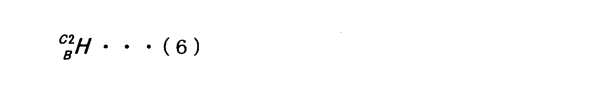

3次元情報統合部145では、例えば、上述したような方法を用いて、俯瞰カメラ101を基準として指定された可動部11の先端の第1の目標可動位置を、手先カメラ112を基準とした可動部11の先端の第2の目標可動位置として変換してもよい。位置算出部141は、第2の目標可動位置に基づいて、目標可動位置に対する可動部11の先端の位置を算出する。
言い換えると、俯瞰カメラ101及び手先カメラ112がマーカM1を撮像し、制御部14が撮像画像の解析処理を行う。この解析処理により、俯瞰カメラ101及び手先カメラ112のそれぞれが、マーカM1との位置情報、位置関係または姿勢情報を取得する。俯瞰カメラ101及び手先カメラ112が同一のマーカM1を撮像しているため、俯瞰カメラ101及び手先カメラ112の相対的な位置関係を取得することができる。これにより、俯瞰カメラ101を基準とした第1の目標把持位置が手先カメラ112を基準とした第2の目標把持位置へ変換され、ロボット1では手先カメラ112から取得された位置情報を用いて、物体を把持することができる。これにより、制御部14の処理負荷を抑制することができる。また、関節111の機械的なガタツキ、撓みなどの要因が排除されるため、ロボット1では、可動部11の先端のエンドエフェクタ113を高精度に物体Hの位置に移動することが可能である。
((可動制御部147))
可動制御部147は、可動部11を制御する機能を有する。可動制御部147は、俯瞰カメラ101及び手先カメラ112を用いて取得した位置情報に応じて算出された第2の目標可動位置と第2の位置情報とに基づいて、可動部11の位置を算出し、可動部11の位置を制御してもよい。さらには、俯瞰カメラ101が、手先カメラ112を視覚範囲内に捉えることにより、手先カメラ112の位置情報と第2の目標把持位置との情報に基づいて、可動部11の先端の位置を制御してもよい。俯瞰カメラ101は、例えば、撮像画像内に手先カメラ112、その周辺のエンドエフェクタ113または可動部11を収め、撮像してもよい。これにより、制御部14にて該撮像画像の画像解析等を行うことで、可動部11の位置をより正確に算出して、可動部11を目標把持位置へ制御してもよい。手先カメラ112の位置情報とは、手先カメラ112が設けられた可動部11がどの位置に存在するか等の空間座標または姿勢情報を含む情報でもよく、手先カメラ112の空間座標または姿勢情報を含む情報でもよい。
可動制御部147は、可動部11を制御する機能を有する。可動制御部147は、俯瞰カメラ101及び手先カメラ112を用いて取得した位置情報に応じて算出された第2の目標可動位置と第2の位置情報とに基づいて、可動部11の位置を算出し、可動部11の位置を制御してもよい。さらには、俯瞰カメラ101が、手先カメラ112を視覚範囲内に捉えることにより、手先カメラ112の位置情報と第2の目標把持位置との情報に基づいて、可動部11の先端の位置を制御してもよい。俯瞰カメラ101は、例えば、撮像画像内に手先カメラ112、その周辺のエンドエフェクタ113または可動部11を収め、撮像してもよい。これにより、制御部14にて該撮像画像の画像解析等を行うことで、可動部11の位置をより正確に算出して、可動部11を目標把持位置へ制御してもよい。手先カメラ112の位置情報とは、手先カメラ112が設けられた可動部11がどの位置に存在するか等の空間座標または姿勢情報を含む情報でもよく、手先カメラ112の空間座標または姿勢情報を含む情報でもよい。
上述のように、俯瞰カメラ101及び手先カメラ112がマーカM1を捉えることにより取得した第1及び第2の位置情報に基づいて、位置算出部141が可動部の位置を算出し、可動制御部147は、関節111に設けられたエンコーダの角度位置を参照しながら、アクチュエータ119を駆動することにより、可動部11の先端の位置を適宜制御することができる。更には、俯瞰カメラ101が手先カメラ112を捉えることにより、俯瞰カメラ101に対する手先カメラ112の位置が、関節111の機械的なガタツキ、撓みなどの要因を含んだ上で判明する。
従って、俯瞰カメラ101が手先カメラ112を視覚範囲内に捉えた場合は、俯瞰カメラ101に対する手先カメラ112の位置が判明し、可動部11のリンクの機械的な形状と関節111に設けられたエンコーダの角度位置に基づいて、可動部11の先端の位置を制御することができる。これにより、移動中に機構的ながたつきにより目標位置への追従精度が低くなってしまうことを確実に回避できる。以上のように、俯瞰カメラ101、手先カメラ112、マーカM1、第1及び第2の目標把持位置の俯瞰カメラ101による位置関係が一度把握できれば、その後は、可動制御部147が、手先カメラ112及び第2の目標把持位置に基づいて俯瞰カメラ101を介さずに、目標位置への追従精度を向上させて可動部11を可動させることができる。また、関節111の機械的なガタツキ、撓みなどの要因が排除されるため、ロボット1は、制御部14の処理負荷を抑制して、可動部11の先端のエンドエフェクタ113を高精度に物体Hの位置に移動することが可能である。
可動制御部147は、可動部11に設けられる手先カメラ112がマーカM1を継続して撮像できるように可動の制御を行ってもよい。例えば、プロジェクタ121とマーカM1との間に可動部11の一部が存在することにより、手先カメラ112が、マーカM1を撮像できない状態となった場合、プロジェクタ121とマーカM1との間とは外れた位置に可動部11を移動させてもよい。手先カメラ112がマーカM1の撮像を継続するほど、可動部11の先端の位置を正確に算出できるため、第2の目標把持位置に対して正確に可動部11を可動できる。
(記憶部15)
記憶部15は、上述した制御部14が各機能を実行するためのプログラムやパラメータを格納する。例えば記憶部15には、投影マーカ制御部143が作成した参考マーカ情報、俯瞰カメラ101及び手先カメラ112が取得した撮像画像等の各種情報、制御部14の処理に用いる各種閾値等が記憶されている。
記憶部15は、上述した制御部14が各機能を実行するためのプログラムやパラメータを格納する。例えば記憶部15には、投影マーカ制御部143が作成した参考マーカ情報、俯瞰カメラ101及び手先カメラ112が取得した撮像画像等の各種情報、制御部14の処理に用いる各種閾値等が記憶されている。
(通信部16)
通信部16は、ネットワーク(例えばインターネットや各種のLAN(Local Area Network)など)を介して各部との間で情報の送受信を行う。例えば、通信部16は、俯瞰カメラ101及び手先カメラ112並びに投影面形状計測センサ122と制御部14とが遠隔して存在する場合に、各センサ101、112、122を用いて取得された情報を制御部14に送信する。
通信部16は、ネットワーク(例えばインターネットや各種のLAN(Local Area Network)など)を介して各部との間で情報の送受信を行う。例えば、通信部16は、俯瞰カメラ101及び手先カメラ112並びに投影面形状計測センサ122と制御部14とが遠隔して存在する場合に、各センサ101、112、122を用いて取得された情報を制御部14に送信する。
以上までで、制御部14、記憶部15及び通信部16を説明した。なお、制御部14は、CPU等のプロセッサ、又はプロセッサとメモリ等の記憶素子が搭載された制御基板等であってもよく、DSPまたはHW(HardWare)回路であってもよい。さらに、制御部14は、上述したそれらの組合せであってもよい。また、制御部14は、PC(Personal Computer)等の汎用的な情報処理装置であってもよい。該制御部14のプロセッサが所定のプログラムに従って演算処理を実行することにより、各種の機能が実現され得る。
<1.3.処理の流れ>
以上、ロボット1の内部構成について説明した。次に、本実施形態に係る処理の流れについて、図7を参照して説明する。図7は、本実施形態に係る処理の流れの一例を示したフローチャートである。
以上、ロボット1の内部構成について説明した。次に、本実施形態に係る処理の流れについて、図7を参照して説明する。図7は、本実施形態に係る処理の流れの一例を示したフローチャートである。
まず、ロボット1は、ロボット1に設けられる電源ボタン等が押されることにより動作を開始する(S100)。
次に、ユーザは、所定の操作方法により、俯瞰カメラ101を基準とした物体H1の把持位置である「第1の目標把持位置」を設定する(S102)。
ユーザが第1の目標把持位置を設定する際には、例えば俯瞰カメラ101の撮像画像をタッチして指定する等して、第1の目標把持位置を設定してもよい。また、ロボット1が自律機能により「第1の目標把持位置」を設定してもよい。
次に、投影面形状計測センサ122が、マーカM1が投影される場所の投影面形状を計測する(S104)。制御部14は、投影面形状計測センサ122を用いて取得された投影面形状の形状情報を処理することにより、位置算出部141におけるマーカM1を介した、俯瞰カメラ101及び手先カメラ112の位置算出が可能となる。
この際に、ロボット1の制御部14は、投影面形状計測センサ122を用いて取得された投影面の形状を記憶部15に記憶する。
次に、制御部14の投影マーカ制御部143は、投影するマーカM1を作成する。作成されたマーカM1は、プロジェクタ121により投影される(S106)。
次に、ロボット1は、該マーカM1を読み取ることができる位置に、俯瞰カメラ101及び手先カメラ112を移動する(S108)。
次に、制御部14にて、俯瞰カメラ101及び手先カメラ112の両方がマーカM1を認識したか否かを判定する(S110)。判定により、俯瞰カメラ及び手先カメラ101、112の両方がマーカM1を認識していない場合(S110/No)は、制御部14は、俯瞰カメラ及び手先カメラ101、112の両方がマーカM1を認識できる位置に、俯瞰カメラ及び手先カメラ101、112を再度移動させる。
上記判定により、俯瞰カメラ及び手先カメラ101、112の両方がマーカM1を認識した場合(S110/Yes)には、ロボット1は次の処理に進行する。
次に、位置算出部141は、俯瞰カメラ101及び手先カメラ112から得られたマーカM1の撮像画像により取得された第1及び第2の位置情報と記憶部15に格納された投影面形状の形状情報と、参考マーカ情報とを照合し、俯瞰カメラ101及び手先カメラ112の位置情報、位置関係または姿勢情報を把握する(S112)。位置情報は、空間内におけるマーカM1を基準とした俯瞰カメラ101及び手先カメラ112の3次元の空間座標を含んでもよく、例えば、(x、y、z)座標にて示されてもよい。位置関係とは、例えば、マーカM1の位置を基準とした俯瞰カメラ101及び手先カメラ112の位置を示してもよく、マーカM1の位置を基準として俯瞰カメラ101及び手先カメラ112が存在する位置までの距離または向きであってもよい。姿勢情報とは、3次元空間のX軸、Y軸、Z軸をそれぞれ軸としてどの程度回転しているかを示す回転角の情報(例えば、ロール角、ピッチ角、ヨー角)を含んでもよい。また姿勢情報は、回転行列またはクォータニオンで示されてもよい。
次に、3次元情報統合部145は、位置算出部141にて算出されたマーカM1に対する俯瞰カメラ101及び手先カメラ112の位置情報、位置関係または姿勢情報に基づいて、俯瞰カメラ101の位置を基準とした第1の目標把持位置を、手先カメラ112を基準とした第2の目標把持位置に変換する。
この変換処理を行うことにより、ロボット1は、俯瞰カメラ101の撮像画像に基づいた画像処理等を用いることなく、物体H1により近い手先カメラ112を用いて、可動部11を可動し、より正確に物体H1を把持できる。
次に、ロボット1は、手先カメラ112を用いて取得された第2の位置情報と第2の目標把持位置とに基づいて、可動部11の先端を制御する(S116)。
次に、制御部14では、可動部11の先端が第2の目標把持位置に到達したか否かの判定を行う(S118)。判定により、可動部11の先端が第2の目標把持位置に到達していない場合(S118/No)は再度、可動制御部147が可動部11を移動させる。
上記判定により、可動部11が第2の目標把持位置に到達した場合(S118/Yes)は、可動部11が物体H1を把持して、ロボット1は動作を終了する(S120)。
<<2.変形例>>
本実施形態においては、ロボット1が物体H1を把持する場合の可動部11の先端の位置算出技術に関して説明を行った。かかる例以外に関しても、本開示の技術は適用され得る。例えば、関節を有する可動部11の位置校正に適用できる。関節を有する可動部11が6自由度以下で可動を行う場合、エンコーダにより各関節の位置及び開度等が決定する。よって、可動部11が可動する際の関節の空間座標が、想定される関節の空間座標と異なる場合に、それらの差を誤差として判別でき、可動部11の校正技術として適用できる。
本実施形態においては、ロボット1が物体H1を把持する場合の可動部11の先端の位置算出技術に関して説明を行った。かかる例以外に関しても、本開示の技術は適用され得る。例えば、関節を有する可動部11の位置校正に適用できる。関節を有する可動部11が6自由度以下で可動を行う場合、エンコーダにより各関節の位置及び開度等が決定する。よって、可動部11が可動する際の関節の空間座標が、想定される関節の空間座標と異なる場合に、それらの差を誤差として判別でき、可動部11の校正技術として適用できる。
以上、添付図面を参照しながら本開示の好適な実施形態について詳細に説明したが、本開示の技術的範囲はかかる例に限定されない。本開示の技術分野における通常の知識を有する者であれば、特許請求の範囲に記載された技術的思想の範疇内において、各種の変更例または修正例に想到し得ることは明らかであり、これらについても、当然に本開示の技術的範囲に属するものと了解される。
また、本明細書に記載された効果は、あくまで説明的または例示的なものであって限定的ではない。つまり、本開示に係る技術は、上記の効果とともに、または上記の効果に代えて、本明細書の記載から当業者には明らかな他の効果を奏しうる。
なお、以下のような構成も本開示の技術的範囲に属する。
(1)
第1の視覚センサが投影されたマーカを読み取ることにより取得された第1の位置情報と、
前記第1の視覚センサと相対的に移動する第2の視覚センサが前記マーカを読み取ることにより取得された位置情報を含む第2の位置情報に基づいて、
前記第2の視覚センサが配置される可動部の位置を算出する位置算出部、を備える情報処理装置。
(2)
前記位置算出部は、前記第1の位置情報、前記第2の位置情報に基づいて、前記可動部の位置を算出し、
前記第2の位置情報は、前記第1の視覚センサを用いて取得される第2の視覚センサの位置情報を含む、前記(1)に記載の情報処理装置。
(3)
前記第1の位置情報は、前記マーカと前記第1の視覚センサとの第1の位置関係または第1の姿勢情報を含む、前記(1)または(2)に記載の情報処理装置。
(4)
前記第1の位置関係とは、前記マーカと前記第1の視覚センサとの間の距離及び方向を表し、
前記第1の姿勢情報とは、前記マーカに対する前記第1の視覚センサの回転角の情報である、前記(3)に記載の情報処理装置。
(5)
前記第2の位置情報は、前記マーカと前記第2の視覚センサとの第2の位置関係または第2の姿勢情報を含む、前記(1)~(4)のいずれか一項に記載の情報処理装置。
(6)
前記第2の位置関係とは、前記マーカと前記第2の視覚センサとの間の距離及び方向を表し、
前記第2の姿勢情報とは、前記マーカに対する前記第2の視覚センサの回転角の情報である、前記(5)に記載の情報処理装置。
(7)
前記第1の視覚センサの位置を基準として指定された前記可動部の第1の目標可動位置を、前記第2の視覚センサの位置を基準とした前記可動部の第2の目標可動位置として変換する3次元情報統合部、を備える、前記(1)~(6)のいずれか一項に記載の情報処理装置。
(8)
前記第2の目標可動位置と前記第2の位置情報とに基づいて、前記可動部の位置を算出し、
前記可動部の位置を制御する可動制御部を更に備える、前記(7)に記載の情報処理装置。
(9)
投影するマーカを制御する投影マーカ制御部を備える、前記(1)~(8)のいずれか一項に記載の情報処理装置。
(10)
前記投影マーカ制御部は、前記第1の視覚センサ及び前記第2の視覚センサの視覚範囲に応じて、前記マーカの投影場所を制御する、前記(9)に記載の情報処理装置。
(11)
前記投影マーカ制御部は、前記マーカを作成する、前記(9)または(10)に記載の情報処理装置。
(12)
前記位置算出部は、投影面形状に基づいて、前記第2の視覚センサが配置される前記可動部の先端の位置を算出する、前記(1)~(11)のいずれか一項に記載の情報処理装置。
(13)
前記マーカは可視光、赤外光及び紫外光を含む、前記(1)~(12)のいずれか一項に記載の情報処理装置。
(14)
前記位置算出部は、物体を把持するエンドエフェクタが設けられる前記可動部の先端の位置を算出する、前記(1)~(13)のいずれか一項に記載の情報処理装置。
(15)
第1の視覚センサが投影されたマーカを読み取ることにより取得された第1の位置情報と、前記第1の視覚センサと相対的に移動する第2の視覚センサが前記マーカを読み取ることにより取得された位置情報を含む第2の位置情報に基づいて、前記第2の視覚センサが配置される可動部の位置を算出する、情報処理方法。
(16)
第1の視覚センサが投影されたマーカを読み取ることにより取得された第1の位置情報と、前記第1の視覚センサと相対的に移動する第2の視覚センサが前記マーカを読み取ることにより取得された位置情報を含む第2の位置情報に基づいて、前記第2の視覚センサが配置される可動部の空間的な位置を算出する位置算出部と、
前記マーカを投影する投影部と、
前記第2の視覚センサが配置され、可動する前記可動部と、
を含む情報処理システム。
10 頭部
11 可動部
12 胴体部
13 移動部
14 制御部
15 記憶部
16 通信部
101 俯瞰カメラ
112 手先カメラ
122 投影面形状計測センサ
11 可動部
12 胴体部
13 移動部
14 制御部
15 記憶部
16 通信部
101 俯瞰カメラ
112 手先カメラ
122 投影面形状計測センサ
Claims (16)
- 第1の視覚センサが投影されたマーカを読み取ることにより取得された第1の位置情報と、
前記第1の視覚センサと相対的に移動する第2の視覚センサが前記マーカを読み取ることにより取得された位置情報を含む第2の位置情報に基づいて、
前記第2の視覚センサが配置される可動部の位置を算出する位置算出部、を備える情報処理装置。 - 前記位置算出部は、前記第1の位置情報、前記第2の位置情報に基づいて、前記可動部の位置を算出し、
前記第2の位置情報は、前記第1の視覚センサを用いて取得される第2の視覚センサの位置情報を含む、請求項1に記載の情報処理装置。 - 前記第1の位置情報は、前記マーカと前記第1の視覚センサとの第1の位置関係または第1の姿勢情報を含む、請求項1に記載の情報処理装置。
- 前記第1の位置関係とは、前記マーカと前記第1の視覚センサとの間の距離及び方向を表し、
前記第1の姿勢情報とは、前記マーカに対する前記第1の視覚センサの回転角の情報である、請求項3に記載の情報処理装置。 - 前記第2の位置情報は、前記マーカと前記第2の視覚センサとの第2の位置関係または第2の姿勢情報を含む、請求項1に記載の情報処理装置。
- 前記第2の位置関係とは、前記マーカと前記第2の視覚センサとの間の距離及び方向を表し、
前記第2の姿勢情報とは、前記マーカに対する前記第2の視覚センサの回転角の情報である、請求項5に記載の情報処理装置。 - 前記第1の視覚センサの位置を基準として指定された前記可動部の第1の目標可動位置を、前記第2の視覚センサの位置を基準とした前記可動部の第2の目標可動位置として変換する3次元情報統合部、を備える、請求項1に記載の情報処理装置。
- 前記第2の目標可動位置と前記第2の位置情報とに基づいて、前記可動部の位置を算出し、
前記可動部の位置を制御する可動制御部を更に備える、請求項7に記載の情報処理装置。 - 投影するマーカを制御する投影マーカ制御部を備える、請求項1に記載の情報処理装置。
- 前記投影マーカ制御部は、前記第1の視覚センサ及び前記第2の視覚センサの視覚範囲に応じて、前記マーカの投影場所を制御する、請求項9に記載の情報処理装置。
- 前記投影マーカ制御部は、前記マーカを作成する、請求項9に記載の情報処理装置。
- 前記位置算出部は、投影面形状に基づいて、前記第2の視覚センサが配置される前記可動部の先端の位置を算出する、請求項1に記載の情報処理装置。
- 前記マーカは可視光、赤外光及び紫外光を含む、請求項1に記載の情報処理装置。
- 前記位置算出部は、物体を把持するエンドエフェクタが設けられる前記可動部の先端の位置を算出する、請求項1に記載の情報処理装置。
- 第1の視覚センサが投影されたマーカを読み取ることにより取得された第1の位置情報と、前記第1の視覚センサと相対的に移動する第2の視覚センサが前記マーカを読み取ることにより取得された位置情報を含む第2の位置情報に基づいて、前記第2の視覚センサが配置される可動部の位置を算出する、情報処理方法。
- 第1の視覚センサが投影されたマーカを読み取ることにより取得された第1の位置情報と、前記第1の視覚センサと相対的に移動する第2の視覚センサが前記マーカを読み取ることにより取得された位置情報を含む第2の位置情報に基づいて、前記第2の視覚センサが配置される可動部の空間的な位置を算出する位置算出部と、
前記マーカを投影する投影部と、
前記第2の視覚センサが配置され、可動する前記可動部と、
を含む情報処理システム。
Priority Applications (4)
| Application Number | Priority Date | Filing Date | Title |
|---|---|---|---|
| CN201880086797.8A CN111615443B (zh) | 2018-01-23 | 2018-10-30 | 信息处理装置、信息处理方法和信息处理系统 |
| US16/962,613 US11420335B2 (en) | 2018-01-23 | 2018-10-30 | Information processing apparatus, information processing method, and information processing system |
| EP18902340.1A EP3744484B1 (en) | 2018-01-23 | 2018-10-30 | Information processing device, information processing method, and information processing system |
| JP2019567861A JP7111114B2 (ja) | 2018-01-23 | 2018-10-30 | 情報処理装置、情報処理方法及び情報処理システム |
Applications Claiming Priority (2)
| Application Number | Priority Date | Filing Date | Title |
|---|---|---|---|
| JP2018008846 | 2018-01-23 | ||
| JP2018-008846 | 2018-01-23 |
Publications (1)
| Publication Number | Publication Date |
|---|---|
| WO2019146201A1 true WO2019146201A1 (ja) | 2019-08-01 |
Family
ID=67394556
Family Applications (1)
| Application Number | Title | Priority Date | Filing Date |
|---|---|---|---|
| PCT/JP2018/040276 WO2019146201A1 (ja) | 2018-01-23 | 2018-10-30 | 情報処理装置、情報処理方法及び情報処理システム |
Country Status (5)
| Country | Link |
|---|---|
| US (1) | US11420335B2 (ja) |
| EP (1) | EP3744484B1 (ja) |
| JP (1) | JP7111114B2 (ja) |
| CN (1) | CN111615443B (ja) |
| WO (1) | WO2019146201A1 (ja) |
Cited By (1)
| Publication number | Priority date | Publication date | Assignee | Title |
|---|---|---|---|---|
| WO2022101178A1 (de) * | 2020-11-11 | 2022-05-19 | Carl Zeiss Ag | Vorrichtung und verfahren zur vermessung, inspektion oder bearbeitung von objekten |
Families Citing this family (7)
| Publication number | Priority date | Publication date | Assignee | Title |
|---|---|---|---|---|
| US11839986B2 (en) * | 2019-10-25 | 2023-12-12 | Ocado Innovation Limited | Systems and methods for active perception and coordination between robotic vision systems and manipulators |
| CN112124825B (zh) * | 2020-09-22 | 2022-10-25 | 同济大学 | 一种垃圾转运装备机械爪定位控制系统 |
| DE102021114268A1 (de) | 2021-06-02 | 2022-12-08 | Bayerische Motoren Werke Aktiengesellschaft | Robotervorrichtung eingerichtet zur Ermittlung einer Infrastrukturobjektlage eines vorbestimmten Infrastrukturobjekts und Verfahren |
| DE102021114264A1 (de) | 2021-06-02 | 2022-12-08 | Bayerische Motoren Werke Aktiengesellschaft | Robotervorrichtung eingerichtet zur Ermittlung einer Interaktionsmaschinenlage zumindest eines Elements einer vorbestimmten Interaktionsmaschine und Verfahren |
| DE102021114265A1 (de) | 2021-06-02 | 2022-12-08 | Bayerische Motoren Werke Aktiengesellschaft | Robotervorrichtung eingerichtet zur Ermittlung einer Zielobjektlage eines vorbestimmten Zielobjekts und Verfahren |
| TWI788134B (zh) * | 2021-12-08 | 2022-12-21 | 財團法人工業技術研究院 | 用於自動控制設備之校正裝置與校正方法 |
| DE102022118970A1 (de) | 2022-07-28 | 2024-02-08 | Bayerische Motoren Werke Aktiengesellschaft | Verfahren zum Bereitstellen und Greifen von Bauteilen durch einen Industrieroboter |
Citations (4)
| Publication number | Priority date | Publication date | Assignee | Title |
|---|---|---|---|---|
| JP2007319938A (ja) | 2006-05-30 | 2007-12-13 | Toyota Motor Corp | ロボット装置及び物体の三次元形状の取得方法 |
| JP2010127719A (ja) * | 2008-11-26 | 2010-06-10 | Canon Inc | 作業システム及び情報処理方法 |
| JP2017076309A (ja) * | 2015-10-16 | 2017-04-20 | セイコーエプソン株式会社 | 画像処理装置、ロボット、ロボットシステム、及びマーカー |
| JP2017124448A (ja) * | 2016-01-12 | 2017-07-20 | 株式会社Ihi | 相対データ較正装置と方法 |
Family Cites Families (13)
| Publication number | Priority date | Publication date | Assignee | Title |
|---|---|---|---|---|
| JPS6015780A (ja) * | 1983-07-08 | 1985-01-26 | Hitachi Ltd | ロボット制御装置 |
| EP2708334B1 (en) * | 2011-05-12 | 2020-05-06 | IHI Corporation | Device and method for controlling prediction of motion |
| JP5854815B2 (ja) * | 2011-12-20 | 2016-02-09 | キヤノン株式会社 | 情報処理装置、情報処理装置の制御方法、およびプログラム |
| JP5912059B2 (ja) * | 2012-04-06 | 2016-04-27 | ソニー株式会社 | 情報処理装置、情報処理方法及び情報処理システム |
| WO2015145543A1 (ja) * | 2014-03-24 | 2015-10-01 | 株式会社日立製作所 | 物体検出装置、物体検出方法、および移動ロボット |
| DE102014009893B4 (de) * | 2014-07-04 | 2016-04-28 | gomtec GmbH | Endeffektor für ein Instrument |
| JP6075343B2 (ja) * | 2014-09-02 | 2017-02-08 | トヨタ自動車株式会社 | 走行ロボット、その動作計画方法及びプログラム |
| JP6415190B2 (ja) * | 2014-09-03 | 2018-10-31 | キヤノン株式会社 | ロボット装置、ロボット制御プログラム、記録媒体、およびロボット装置の制御方法 |
| CN106607907B (zh) * | 2016-12-23 | 2017-09-26 | 西安交通大学 | 一种移动视觉机器人及其测控方法 |
| JP6640792B2 (ja) * | 2017-06-30 | 2020-02-05 | ファナック株式会社 | ハンド制御装置、ハンド制御方法、およびハンドのシミュレーション装置 |
| JP7289616B2 (ja) * | 2017-06-30 | 2023-06-12 | キヤノン株式会社 | ロボットハンド、ロボット装置、ロボットハンドの制御方法 |
| EP3658340A2 (en) | 2017-07-25 | 2020-06-03 | MBL Limited | Systems and methods for operating a robotic system and executing robotic interactions |
| US10792809B2 (en) * | 2017-12-12 | 2020-10-06 | X Development Llc | Robot grip detection using non-contact sensors |
-
2018
- 2018-10-30 US US16/962,613 patent/US11420335B2/en active Active
- 2018-10-30 EP EP18902340.1A patent/EP3744484B1/en active Active
- 2018-10-30 JP JP2019567861A patent/JP7111114B2/ja active Active
- 2018-10-30 WO PCT/JP2018/040276 patent/WO2019146201A1/ja unknown
- 2018-10-30 CN CN201880086797.8A patent/CN111615443B/zh active Active
Patent Citations (4)
| Publication number | Priority date | Publication date | Assignee | Title |
|---|---|---|---|---|
| JP2007319938A (ja) | 2006-05-30 | 2007-12-13 | Toyota Motor Corp | ロボット装置及び物体の三次元形状の取得方法 |
| JP2010127719A (ja) * | 2008-11-26 | 2010-06-10 | Canon Inc | 作業システム及び情報処理方法 |
| JP2017076309A (ja) * | 2015-10-16 | 2017-04-20 | セイコーエプソン株式会社 | 画像処理装置、ロボット、ロボットシステム、及びマーカー |
| JP2017124448A (ja) * | 2016-01-12 | 2017-07-20 | 株式会社Ihi | 相対データ較正装置と方法 |
Non-Patent Citations (1)
| Title |
|---|
| See also references of EP3744484A4 |
Cited By (1)
| Publication number | Priority date | Publication date | Assignee | Title |
|---|---|---|---|---|
| WO2022101178A1 (de) * | 2020-11-11 | 2022-05-19 | Carl Zeiss Ag | Vorrichtung und verfahren zur vermessung, inspektion oder bearbeitung von objekten |
Also Published As
| Publication number | Publication date |
|---|---|
| JPWO2019146201A1 (ja) | 2021-01-28 |
| JP7111114B2 (ja) | 2022-08-02 |
| CN111615443B (zh) | 2023-05-26 |
| EP3744484A4 (en) | 2021-03-17 |
| EP3744484B1 (en) | 2023-07-05 |
| CN111615443A (zh) | 2020-09-01 |
| US11420335B2 (en) | 2022-08-23 |
| EP3744484A1 (en) | 2020-12-02 |
| US20200406465A1 (en) | 2020-12-31 |
Similar Documents
| Publication | Publication Date | Title |
|---|---|---|
| WO2019146201A1 (ja) | 情報処理装置、情報処理方法及び情報処理システム | |
| JP3859574B2 (ja) | 3次元視覚センサ | |
| JP6180087B2 (ja) | 情報処理装置及び情報処理方法 | |
| JP6021533B2 (ja) | 情報処理システム、装置、方法及びプログラム | |
| JP4914039B2 (ja) | 情報処理方法および装置 | |
| JP5928114B2 (ja) | ロボットシステム、ロボットシステムのキャリブレーション方法、ロボット | |
| JP6324025B2 (ja) | 情報処理装置、情報処理方法 | |
| KR20140008262A (ko) | 로봇 시스템, 로봇, 로봇 제어 장치, 로봇 제어 방법 및 로봇 제어 프로그램 | |
| JP6317618B2 (ja) | 情報処理装置およびその方法、計測装置、並びに、作業装置 | |
| JP2016099257A (ja) | 情報処理装置及び情報処理方法 | |
| JP2019069493A (ja) | ロボットシステム | |
| JP6897396B2 (ja) | 制御装置、ロボットシステムおよび制御方法 | |
| JP2019155556A (ja) | ロボットの制御装置、ロボット、ロボットシステム、並びに、カメラの校正方法 | |
| WO2018043524A1 (ja) | ロボットシステム、ロボットシステム制御装置、およびロボットシステム制御方法 | |
| JP4533193B2 (ja) | 情報処理装置および情報処理方法 | |
| JP4227037B2 (ja) | 撮像システム及び校正方法 | |
| JP2009175012A (ja) | 計測装置および計測方法 | |
| WO2023013740A1 (ja) | ロボット制御装置、ロボット制御システム、及びロボット制御方法 | |
| JP2005205519A (ja) | ロボットハンド装置 | |
| JP2006007390A (ja) | 撮像装置、撮像方法、撮像プログラム、撮像プログラムを記録したコンピュータ読取可能な記録媒体 | |
| JP3160443B2 (ja) | 非接触点教示装置 | |
| JP2005186193A (ja) | ロボットのキャリブレーション方法および三次元位置計測方法 | |
| JP7174389B1 (ja) | 物体位置推定表示装置、方法及びプログラム | |
| US20230054929A1 (en) | Optical registration in a computer-aided system | |
| JP2021091070A (ja) | ロボット制御装置 |
Legal Events
| Date | Code | Title | Description |
|---|---|---|---|
| 121 | Ep: the epo has been informed by wipo that ep was designated in this application |
Ref document number: 18902340 Country of ref document: EP Kind code of ref document: A1 |
|
| ENP | Entry into the national phase |
Ref document number: 2019567861 Country of ref document: JP Kind code of ref document: A |
|
| NENP | Non-entry into the national phase |
Ref country code: DE |
|
| ENP | Entry into the national phase |
Ref document number: 2018902340 Country of ref document: EP Effective date: 20200824 |