EP2707044B1 - Implantable materials having engineered surfaces and method of making same - Google Patents
Implantable materials having engineered surfaces and method of making same Download PDFInfo
- Publication number
- EP2707044B1 EP2707044B1 EP12786428.8A EP12786428A EP2707044B1 EP 2707044 B1 EP2707044 B1 EP 2707044B1 EP 12786428 A EP12786428 A EP 12786428A EP 2707044 B1 EP2707044 B1 EP 2707044B1
- Authority
- EP
- European Patent Office
- Prior art keywords
- implantable
- physiologically functional
- layer
- functional features
- biocompatible
- Prior art date
- Legal status (The legal status is an assumption and is not a legal conclusion. Google has not performed a legal analysis and makes no representation as to the accuracy of the status listed.)
- Active
Links
Images


Classifications
-
- A—HUMAN NECESSITIES
- A61—MEDICAL OR VETERINARY SCIENCE; HYGIENE
- A61L—METHODS OR APPARATUS FOR STERILISING MATERIALS OR OBJECTS IN GENERAL; DISINFECTION, STERILISATION OR DEODORISATION OF AIR; CHEMICAL ASPECTS OF BANDAGES, DRESSINGS, ABSORBENT PADS OR SURGICAL ARTICLES; MATERIALS FOR BANDAGES, DRESSINGS, ABSORBENT PADS OR SURGICAL ARTICLES
- A61L31/00—Materials for other surgical articles, e.g. stents, stent-grafts, shunts, surgical drapes, guide wires, materials for adhesion prevention, occluding devices, surgical gloves, tissue fixation devices
- A61L31/14—Materials characterised by their function or physical properties, e.g. injectable or lubricating compositions, shape-memory materials, surface modified materials
- A61L31/16—Biologically active materials, e.g. therapeutic substances
-
- A—HUMAN NECESSITIES
- A61—MEDICAL OR VETERINARY SCIENCE; HYGIENE
- A61F—FILTERS IMPLANTABLE INTO BLOOD VESSELS; PROSTHESES; DEVICES PROVIDING PATENCY TO, OR PREVENTING COLLAPSING OF, TUBULAR STRUCTURES OF THE BODY, e.g. STENTS; ORTHOPAEDIC, NURSING OR CONTRACEPTIVE DEVICES; FOMENTATION; TREATMENT OR PROTECTION OF EYES OR EARS; BANDAGES, DRESSINGS OR ABSORBENT PADS; FIRST-AID KITS
- A61F2/00—Filters implantable into blood vessels; Prostheses, i.e. artificial substitutes or replacements for parts of the body; Appliances for connecting them with the body; Devices providing patency to, or preventing collapsing of, tubular structures of the body, e.g. stents
- A61F2/0077—Special surfaces of prostheses, e.g. for improving ingrowth
-
- A—HUMAN NECESSITIES
- A61—MEDICAL OR VETERINARY SCIENCE; HYGIENE
- A61F—FILTERS IMPLANTABLE INTO BLOOD VESSELS; PROSTHESES; DEVICES PROVIDING PATENCY TO, OR PREVENTING COLLAPSING OF, TUBULAR STRUCTURES OF THE BODY, e.g. STENTS; ORTHOPAEDIC, NURSING OR CONTRACEPTIVE DEVICES; FOMENTATION; TREATMENT OR PROTECTION OF EYES OR EARS; BANDAGES, DRESSINGS OR ABSORBENT PADS; FIRST-AID KITS
- A61F2/00—Filters implantable into blood vessels; Prostheses, i.e. artificial substitutes or replacements for parts of the body; Appliances for connecting them with the body; Devices providing patency to, or preventing collapsing of, tubular structures of the body, e.g. stents
- A61F2/02—Prostheses implantable into the body
-
- A—HUMAN NECESSITIES
- A61—MEDICAL OR VETERINARY SCIENCE; HYGIENE
- A61P—SPECIFIC THERAPEUTIC ACTIVITY OF CHEMICAL COMPOUNDS OR MEDICINAL PREPARATIONS
- A61P43/00—Drugs for specific purposes, not provided for in groups A61P1/00-A61P41/00
-
- C—CHEMISTRY; METALLURGY
- C23—COATING METALLIC MATERIAL; COATING MATERIAL WITH METALLIC MATERIAL; CHEMICAL SURFACE TREATMENT; DIFFUSION TREATMENT OF METALLIC MATERIAL; COATING BY VACUUM EVAPORATION, BY SPUTTERING, BY ION IMPLANTATION OR BY CHEMICAL VAPOUR DEPOSITION, IN GENERAL; INHIBITING CORROSION OF METALLIC MATERIAL OR INCRUSTATION IN GENERAL
- C23C—COATING METALLIC MATERIAL; COATING MATERIAL WITH METALLIC MATERIAL; SURFACE TREATMENT OF METALLIC MATERIAL BY DIFFUSION INTO THE SURFACE, BY CHEMICAL CONVERSION OR SUBSTITUTION; COATING BY VACUUM EVAPORATION, BY SPUTTERING, BY ION IMPLANTATION OR BY CHEMICAL VAPOUR DEPOSITION, IN GENERAL
- C23C14/00—Coating by vacuum evaporation, by sputtering or by ion implantation of the coating forming material
- C23C14/04—Coating on selected surface areas, e.g. using masks
- C23C14/042—Coating on selected surface areas, e.g. using masks using masks
-
- C—CHEMISTRY; METALLURGY
- C23—COATING METALLIC MATERIAL; COATING MATERIAL WITH METALLIC MATERIAL; CHEMICAL SURFACE TREATMENT; DIFFUSION TREATMENT OF METALLIC MATERIAL; COATING BY VACUUM EVAPORATION, BY SPUTTERING, BY ION IMPLANTATION OR BY CHEMICAL VAPOUR DEPOSITION, IN GENERAL; INHIBITING CORROSION OF METALLIC MATERIAL OR INCRUSTATION IN GENERAL
- C23C—COATING METALLIC MATERIAL; COATING MATERIAL WITH METALLIC MATERIAL; SURFACE TREATMENT OF METALLIC MATERIAL BY DIFFUSION INTO THE SURFACE, BY CHEMICAL CONVERSION OR SUBSTITUTION; COATING BY VACUUM EVAPORATION, BY SPUTTERING, BY ION IMPLANTATION OR BY CHEMICAL VAPOUR DEPOSITION, IN GENERAL
- C23C14/00—Coating by vacuum evaporation, by sputtering or by ion implantation of the coating forming material
- C23C14/22—Coating by vacuum evaporation, by sputtering or by ion implantation of the coating forming material characterised by the process of coating
- C23C14/24—Vacuum evaporation
-
- C—CHEMISTRY; METALLURGY
- C23—COATING METALLIC MATERIAL; COATING MATERIAL WITH METALLIC MATERIAL; CHEMICAL SURFACE TREATMENT; DIFFUSION TREATMENT OF METALLIC MATERIAL; COATING BY VACUUM EVAPORATION, BY SPUTTERING, BY ION IMPLANTATION OR BY CHEMICAL VAPOUR DEPOSITION, IN GENERAL; INHIBITING CORROSION OF METALLIC MATERIAL OR INCRUSTATION IN GENERAL
- C23C—COATING METALLIC MATERIAL; COATING MATERIAL WITH METALLIC MATERIAL; SURFACE TREATMENT OF METALLIC MATERIAL BY DIFFUSION INTO THE SURFACE, BY CHEMICAL CONVERSION OR SUBSTITUTION; COATING BY VACUUM EVAPORATION, BY SPUTTERING, BY ION IMPLANTATION OR BY CHEMICAL VAPOUR DEPOSITION, IN GENERAL
- C23C14/00—Coating by vacuum evaporation, by sputtering or by ion implantation of the coating forming material
- C23C14/58—After-treatment
- C23C14/5873—Removal of material
-
- G—PHYSICS
- G03—PHOTOGRAPHY; CINEMATOGRAPHY; ANALOGOUS TECHNIQUES USING WAVES OTHER THAN OPTICAL WAVES; ELECTROGRAPHY; HOLOGRAPHY
- G03F—PHOTOMECHANICAL PRODUCTION OF TEXTURED OR PATTERNED SURFACES, e.g. FOR PRINTING, FOR PROCESSING OF SEMICONDUCTOR DEVICES; MATERIALS THEREFOR; ORIGINALS THEREFOR; APPARATUS SPECIALLY ADAPTED THEREFOR
- G03F7/00—Photomechanical, e.g. photolithographic, production of textured or patterned surfaces, e.g. printing surfaces; Materials therefor, e.g. comprising photoresists; Apparatus specially adapted therefor
- G03F7/20—Exposure; Apparatus therefor
-
- A—HUMAN NECESSITIES
- A61—MEDICAL OR VETERINARY SCIENCE; HYGIENE
- A61L—METHODS OR APPARATUS FOR STERILISING MATERIALS OR OBJECTS IN GENERAL; DISINFECTION, STERILISATION OR DEODORISATION OF AIR; CHEMICAL ASPECTS OF BANDAGES, DRESSINGS, ABSORBENT PADS OR SURGICAL ARTICLES; MATERIALS FOR BANDAGES, DRESSINGS, ABSORBENT PADS OR SURGICAL ARTICLES
- A61L2400/00—Materials characterised by their function or physical properties
- A61L2400/18—Modification of implant surfaces in order to improve biocompatibility, cell growth, fixation of biomolecules, e.g. plasma treatment
Definitions
- the present invention relates generally to implantable medical devices and more particularly to controlling surface properties of implantable biocompatible materials suitable for fabrication of implantable medical devices.
- Implantable medical devices are fabricated of materials that are sub-optimal in terms of the biological response they elicit in vivo.
- Many conventional materials used to fabricate 0 implantable devices such as titanium, polytetrafluoroethylene, silicone, carbon fiber and polyester, are used because of their strength and physiologically inert characteristics.
- tissue integration onto these materials is typically slow and inadequate.
- Certain materials, such as silicone and polyester elicit a significant inflammatory, foreign body response that drives fibrous encapsulation of the synthetic material. The fibrous encapsulation may have significant adverse effects on the implant.
- conventional biomaterials have proved inadequate in eliciting a sufficient healing response necessary for complete device integration into the body. For example, in devices that contact blood, such as stents and vascular grafts, attempts to modify such devices to promote endothelial cell adhesion may have a concomitant effect of making the devices more thrombogenic.
- US 2005/232968 A1 discloses an implantable, biocompatible material, of which at least one surface has a patterned array of features having at least one of chemical, physiochemical and electrochemical activity different than regions without the features.
- WO 01/87371 A2 relates to an implantable medical device comprising a self-supporting structural member fabricated of a plurality of laminated layers of at least one biocompatible material.
- US 5 849 206 A discloses a method of producing a biocompatible prosthesis based on a substrate made essentially of metal or ceramic.
- US 2003/028244 A1 discloses a coated implantable medical device that includes a structure adapted for introduction into a vascular system, esophagus, trachea, colon, biliary tract, or urinary tract; a layer of an immunosuppressive agent posited on one surface of the structure; and a porous layer posited over the layer of an immunosuppressive agent.
- US 2010/227372 A1 relates to an activated metallic, semiconductor, polymer, composite and/or ceramic substrate that is bound through a mixed or graded interface to a hydrophilic plasma polymer surface. The polymer surface is activated to enable direct covalent binding to a functional biological molecule, and comprises a sub-surface that includes a plurality of cross-linked regions.
- WO 2012/154862 A2 discloses an implantable medical device having enhanced endothelial migration features.
- Baier, RE & Meyer, AE, 1988 (The International Journal of Oral & Maxillofacial Implants, 1 January 1988, 9-20 ) provide an overview on ways of providing prosthetic implants that are scrupulously free of contaminating overlayers at the instant of their biological placement.
- EP0606566 relates to a method and device for preparing implant surfaces of metallic or ceramic material, using gas-discharge plasma with the aim of obtaining a well-defined and reproducible implant surface.
- the present invention is defined by the implantable, biocompatible material according to appended claim 1.
- the present invention is furthermore defined by the method for making the implantable, biocompatible material according to appended claim 11.
- an implantable biocompatible material includes one or more vacuum deposited layers of biocompatible materials deposited upon a biocompatible base material. At least a top most vacuum deposited layer includes a homogeneous molecular pattern of distribution along the surface thereof and comprises a patterned array of geometric physiologically functional features.
- an implantable biocompatible material in another embodiment, includes a plurality of layers of biocompatible materials formed upon one another into a self-supporting multilayer structure.
- the plurality of layers includes a vacuum deposited surface layer having a homogeneous molecular pattern of distribution along the surface thereof and comprises a patterned array of geometric physiologically functional features.
- a method for making an implantable biocompatible material includes the steps of providing an implantable biocompatible material having at least one surface intended to contact tissue of body fluids in vivo and providing a mask having a defined pattern of openings corresponding in size and spacing to a predetermined distribution of binding domains to be imparted to the at least one surface.
- the method further includes the steps of treating the at least one surface of the biocompatible material through the mask by at least one of three techniques.
- the first technique includes vacuum depositing a layer of material onto the at least one surface, wherein the vacuum deposited layer is different from the at least one surface immediately therebeneath in a material property selected from the group of material properties consisting of: grain size, grain phase, grain material composition, surface topography, and transition temperature, and removing the mask to yield a plurality of binding domains defined on the at least one surface of the implantable, biocompatible material.
- the second technique includes vacuum depositing a layer of sacrificial material onto the at least one surface, removing the mask from the at least one surface, vacuum depositing a second layer of material onto the at least one surface, wherein the second vacuum deposited layer is different from the at least one surface immediately therebeneath in a material property selected from the group of material properties consisting of: grain size, grain phase, grain material composition, surface topography, and transition temperature, and removing the sacrificial material to yield a plurality of binding domains defined on the at least one surface of the implantable, biocompatible material.
- the third technique includes photo irradiating the at least one surface to photochemically alter the at least one surface, and removing the mask to yield a plurality of binding domains defined on the at least one surface of the implantable, biocompatible material.
- the capacity for complete endothelialization of conventional implantable materials may be enhanced by imparting a pattern of chemically and/or physiochemically active geometric physiologically functional features onto a blood contacting surface of the implantable material.
- inventive implantable devices may be fabricated of polymers, pre-existing conventional wrought metallic materials, such as stainless steel or nitinol hypotubes, or may be fabricated by thin film vacuum deposition techniques.
- the inventive implantable devices may be intravascular stent, stent-grafts, grafts, heart valves, venous valves, filters, occlusion devices, catheters, osteal implants, implantable contraceptives, implantable antitumor pellets or rods, shunts and patches, or other implantable medical devices having any construction or made of any material as will be hereinafter described.
- a medical device is an instrument, apparatus, implant, in vitro reagent, or other similar or related article, which is intended for use in the diagnosis of disease or other conditions, or in the cure, mitigation, treatment, or prevention of disease, or intended to affect the structure or any function of the body and which does not achieve any of it's primary intended purposes through chemical action within or on the body.
- intravascular stents are also believed to be applicable to the manufacturing of any type of intravascular medical device, stent-grafts, grafts, heart valves, venous valves, filters, occlusion devices, catheters, osteal implants, implantable contraceptives, implantable antitumor pellets or rods, shunts and patches, pacemakers, medical wires or medical tubes for any type of medical device, or other implantable medical devices, as will also be hereinafter described.
- a pacemaker or artificial pacemaker, so as not to be confused with the heart's natural pacemaker
- the electrodes may be covered by tubing or other material that includes a surface that may require endothelialization and grooves thereon.
- inventive implantable metal devices may be fabricated of polymers, pre-existing conventional wrought metallic materials, such as stainless steel or nitinol hypotubes, or may be fabricated by thin film vacuum deposition techniques.
- inventive implantable materials and resulting devices by vacuum deposition of either or both of the base implant material and the chemically and/or physiochemically active geometric physiologically functional features.
- Vacuum deposition permits greater control over many material characteristics and properties of the resulting material and formed device. For example, vacuum deposition permits control over grain size, grain phase, grain material composition, bulk material composition, surface topography, mechanical properties, such as transition temperatures in the case of a shape memory alloy.
- vacuum deposition processes will permit creation of devices with greater material purity without the introduction of large quantities of contaminants that adversely affect the material and, therefore, the mechanical and/or biological properties of the implanted device.
- Vacuum deposition techniques also lend themselves to fabrication of more complex devices than those that are manufactured by conventional cold-working techniques. For example, multi-layer structures, complex geometrical configurations, extremely fine control over material tolerances, such as thickness or surface uniformity, are all advantages of vacuum deposition processing.
- the embodiments disclosed herein to may replace polymer grafts with metal grafts that can potentially become covered with EC and can heal completely.
- heterogeneities of materials in contact with blood flow are preferably controlled by using vacuum deposited materials.
- vacuum deposition materials are formed directly in the desired geometry, e.g., planar, tubular, etc.
- the common principle of vacuum deposition processes is to take a material in a minimally processed form, such as pellets or thick foils, known as the source material and atomize them. Atomization may be carried out using heat, as is the case in physical vapor deposition, or using the effect of collisional processes, as in the case of sputter deposition, for example.
- a process such as laser ablation, which creates microparticles that typically consist of one or more atoms, may replace atomization; the number of atoms per particle may be in the thousands or more.
- the atoms or particles of the source material are then deposited on a substrate or mandrel to directly form the desired object.
- chemical reactions between ambient gas introduced into the vacuum chamber, i.e., the gas source, and the deposited atoms and/or particles are part of the deposition process.
- the deposited material includes compound species that are formed due to the reaction of the solid source and the gas source, such as in the case of chemical vapor deposition. In most cases, the deposited material is then either partially or completely removed from the substrate, to form the desired product.
- a first advantage of vacuum deposition processing is that vacuum deposition of the metallic and/or pseudometallic films permits tight process control and films may be deposited that have a regular, homogeneous atomic and molecular pattern of distribution along their fluid-contacting surfaces. This avoids the marked variations in surface composition, creating predictable oxidation and organic adsorption patterns and has predictable interactions with water, electrolytes, proteins and cells.
- EC migration is supported by a homogeneous distribution of binding domains that serve as natural or implanted cell attachment sites in order to promote unimpeded migration and attachment.
- the inventive grafts may be comprised of a layer of biocompatible material or of a plurality of layers of biocompatible materials formed upon one another into a self-supporting multilayer structure because multilayer structures increase the mechanical strength of sheet materials, or to provide special qualities by including layers that have special properties such as superelasticity, shape memory, radio-opacity, corrosion resistance etc.
- Vacuum deposition technologies may deposit layered materials and thus films possessing exceptional qualities may be produced.
- Layered materials, such as superstructures or multilayers are commonly deposited to take advantage of some chemical, electronic, or optical property of the material as a coating; a common example is an antireflective coating on an optical lens.
- Multilayers are also used in the field of thin film fabrication to increase the mechanical properties of the thin film, specifically hardness and toughness.
- vacuum deposition is an additive technique that lends itself toward fabrication of substantially uniformly thin materials with potentially complex three dimensional geometries and structures that cannot be cost-effectively achieved, or in some cases achieved at all, by employing conventional wrought fabrication techniques.
- Conventional wrought metal fabrication techniques may entail smelting, hot working, cold working, heat treatment, high temperature annealing, precipitation annealing, grinding, ablation, wet etching, dry etching, cutting and welding. All of these processing steps have disadvantages including contamination, material property degradation, ultimate achievable configurations, dimensions and tolerances, biocompatibility and cost.
- conventional wrought processes are not suitable for fabricating tubes having diameters greater than about 20 mm, nor are such processes suitable for fabricating materials having wall thicknesses down to about 1 ⁇ m with sub- ⁇ m tolerances.
- the embodiments disclosed herein takes advantage of the discovered relationship between chemically or physiochemically-active geometric physiologically functional features defined and distributed on a blood contact surface and enhanced endothelial cell binding, proliferation and migration over the blood contact surface of the implantable material.
- the embodiments disclosed herein involve focal adhesion point formation during cellular movement and the anchorage dependence, that spreading cells proliferate faster than non-spreading cells.
- the geometric physiologically functional features disclosed herein may be formed on, in, or through one or more layers of vacuum deposited biocompatible material.
- the one or more layers of vacuum deposited biocompatible material are deposited on a layer of bulk material.
- a plurality of layers of vacuum deposited biocompatible material is deposited on one another to form a self-supporting multilayer structure.
- the geometric physiologically functional features may have a non-zero thickness corresponding to a thickness of one or more layers of the vacuum deposited material.
- the geometric physiologically functional features may have a zero thickness or a thickness greater than one or more layers of the vacuum deposited material.
- Geometric physiologically functional features having thicknesses greater than 3 ⁇ m and up to about 20 ⁇ m may also be employed in the embodiments disclosed herein, it being understood that as the thickness of the geometric physiologically functional feature increases there is a decreasing chemical and/or electrochemical interaction between the geometric physiologically functional feature and the endothelial cells and an increasing physical interaction (topographic guidance effect).
- UV irradiation may be employed to oxidize titanium or titanium-alloy surfaces, photochemical alteration of the surface titanium oxides alter the hydrophobicity of the exposed titanium oxides and act as affinity binding and migration sites for endothelial cell attachment and proliferation across a titanium or titanium-alloy surface.
- the thickness of the photochemically altered regions of titanium oxide are, for all practical purposes, 0 ⁇ m.
- the term "geometric physiologically functional features" is intended to include both physical members and photochemically-altered regions having thicknesses having thicknesses down to 0 ⁇ m.
- FIG. 1 a portion of an implantable material 10 showing the surface material 12 with described elevated geometric physiologically functional features 14 is illustrated.
- the geometric physiologically functional features are elevated from the surface of the implantable material to a height ranging from about 1 nm to about 20 ⁇ m.
- the height of the geometric physiologically functional feature 14 ranges from about 1 nm to about 3 ⁇ m.
- the shape of geometric physiologically functional features can be either circular, square, rectangle, triangle, parallel lines, straight or curvilinear lines or any combination thereof.
- Each of the geometric physiologically functional features is preferably from about 1 nm to about 75 ⁇ m, and preferably from about 1nm to 50 ⁇ m in feature width 16, or feature diameter if the geometric physiologically functional feature is circular.
- a gap distance 18 between each of the geometric physiologically functional features may be less than, about equal to or greater than the feature width 16, i.e., between about 1 nm to about 75 ⁇ m edge-to-edge.
- FIG. 2 is a cross-sectional view along line 2-2 in FIG. 1 .
- One of the elevated geometric physiologically functional features 14 is shown on the surface 12 of the implantable material.
- a layer of a titanium or titanium-alloy material 20 is heating to oxidize and form titanium dioxide on the surface of the material 20.
- the layer of titanium or titanium-alloy material 20 is deposited over one or more layers of vacuum deposited material in a self-supporting multilayer structure.
- the layer of titanium or titanium-alloy material 20 is deposited over a bulk material that may have one or more layers of vacuum deposited material deposited thereon.
- the geometric physiologically functional features 24 are formed by exposing the layer of material 20 to UV through a pattern mask. UV irradiation alters the titanium oxides in the areas of geometric physiologically functional features 24, thereby chemically altering the geometric physiologically functional features 24 relative to the surrounding the surrounding surface area 22 of material layer of material 20.
- the shape of geometric physiologically functional features can be circular, square, rectangle, triangle, parallel lines, intersecting lines or any combination.
- Each of the geometric physiologically functional features is from about 1 nanometer to about 75 ⁇ m, and preferably from about 1 nanometer to about 50 ⁇ m in feature width 16, or feature diameter if the geometric physiologically functional feature is circular.
- the gap distance 28 between each component of the geometric physiologically functional features may be less than, about equal to or greater than the feature width 26.
- FIG. 4 is a cross-sectional view of FIG. 3 along line 4-4.
- the described geometric physiologically functional features 24 are indicated by the dotted lines, which indicate that the geometric physiologically functional features 24 are at the same level of the surrounding surface 22.
- FIG. 5 shows geometric physiologically functional features that are evenly distributed across the at least one surface of the implantable material that contacts body fluid, preferably blood.
- the geometric physiologically functional features are elevated from the rest of the surface to a height ranging from about 1 nanometer to about 20 micrometers.
- the height of the geometric physiologically functional feature ranges from about 1 nanometer to about 3 micrometers.
- the shape of the geometric physiologically functional features is not confined within the shape that is shown.
- the shape of the chemically defined domain can also be any of circle, square, rectangle, and triangle, parallel lines, intersecting lines or any combination of the above.
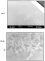
- FIG. 6A shows the cell 32 spreading on the surface of hydrophilic treated Si.
- FIG. 6B shows the cell 32 spreading on the surface of hydrophilic treated Si with circular dots that are 15 microns in diameter. Cells in FIG. 6B appear to have much more focal adhesion points 36 than those in FIG. 6A . Because these geometric physiologically functional features provide for cell attachment, acting as affinity domains, the size of each of these affinity domains relative to the size of an endothelial cell determines the availability of affinity domains to the subsequent round of cell movement.
- the preferred size of each of the individual component of the geometric physiologically functional features is about 1 nm to about 75 ⁇ m, and preferably from about 1 nm to 50 ⁇ m in feature width, or diameter if the geometric physiologically functional feature is circular.
- Focal adhesion point formation is the critical step in cell movement and cell proliferation; therefore, geometric physiologically functional features such as carbon dots on the hydrophilic Si surface promote cell movement.
- Spreading of cells promotes cell proliferation, protein synthesis, and other cell metabolic functions. Promoting cell movement and cell proliferation ultimately accelerates covering of the implanted implantable material with endothelial cells on exposed surfaces having the geometric physiologically functional features.
- the geometric physiologically functional features shown in FIG. 6B are circular, the shape of the geometric physiologically functional features are not limited to this particular embodiment.
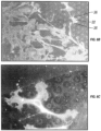
- FIG. 6C is a magnification of a portion of the image of FIG. 6B .
- Multiple focal adhesion points 36 are again shown.
- Wide spreading of the cell is primarily due to the formation of multiple focal adhesion points on the circular geometric physiologically functional features. Extensive spreading of the cells is beneficial towards endothelialization because it promotes cell movement and cell proliferation.
- FIG. 7 shows the stained focal adhesion points 36 of human aotic endothelial cells (HAEC) on the surface of an implantable material with geometric physiologically functional features 14 that are in the form of carbon dots.
- the focal adhesion points are located at or very close to the geometric physiologically functional features 14. These focal adhesion points serve as tension points for the cell to contract from the opposite end of the cell and hence promote cell movement.
- FIG. 8A shows the wide spreading of cells 32 and focal multiple focal adhesion points 36 on the surface of an implantable material with geometric physiologically functional features that are in the form of NiTi dots of 25 micrometers in diameter.
- the NiTi dots are invisible due to the weak contrast between the NiTi dots and surrounding Si surface.
- FIG. 8B shows a magnified slide of a human aortic epithelial cell 32, as shown in FIG. 8A .
- Multiple focal adhesion points 36 are shown to encapsulate the NiTi dots patterned on the hydrophilic Si surface.
- FIG. 9A a portion of an implantable material 46 with surface 42 and 44 is shown.
- a machined mask 48 having laser-cut holes 40 of defined size ranging from about 1 nm to about 75 ⁇ m, and preferably from about 1 nm to 50 ⁇ m, patterned throughout coats at least one surface 42 of the implantable material 46 and is tightly adhered to the covered surface 42.
- a thin film of material 14 was deposited into the space as defined by the holes 40, as seen in FIG. 9B , in the mask 48 by thin film deposition procedures.
- the mask is removed to reveal the geometric physiologically functional features 49 patterned across the at least one surface 42 of the implantable material 46.
- the shape of the holes in the mask could be in any of the shapes described for the geometric physiologically functional features including: circle, square, rectangle, triangle, parallel lines and intersecting lines, or any combination thereof.
- the geometric physiologically functional features are elevated from the surface of the implantable material.
- the thickness of the geometric physiologically functional features is based upon the thickness of the holes in the mask, the thickness ranging from about 1 nm to about 20 micrometers. Preferably, the thickness of the holes in the mask range from about 1 nm to about 3 micrometers.
- the variations of geometric physiologically functional features may be added to a surface of an implantable biocompatible material by vacuum depositing a layer or layers of biocompatible material on the surface.
- the geometry of the layer or layers of deposited material defines the geometric physiologically functional features.
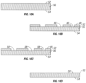
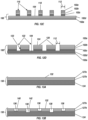
- an implantable material 100 has a surface 104, as illustrated in FIG. 11A .
- the implantable biocompatible material may comprise one or more layers 102 of vacuum deposited material formed into a self-supporting structure, as illustrated by FIG. 11A showing a first layer 102a, a second layer 102b, a third layer 102c, a fourth layer 102d, and a fifth layer 102e.
- the implantable biocompatible material includes a bulk material, either a bulk material alone or a bulk material covered by the one or more layers 102a-102e of vacuum deposited biocompatible material. Five layers 102a-102e of vacuum deposited material are illustrated; however, any number of layers may be included as desired or appropriate.
- the one or more layers 102 may have thicknesses that are the same or different as desired or appropriate. Each layer may have a thickness in a range from about 1 nanometer to about 20 micrometers, from about 1 nanometer to about 10 micrometers, from about 1 nanometer to about 5 micrometers, or from about 1 nanometer to about 3 micrometers. Alternating layers 102 of varying thicknesses may be applied as to accommodate the geometric physiologically functional features.
- the geometric physiologically functional features may be added to the surface 104 by adding one or more layers 102 of vacuum deposited material.
- a mask 106 having holes 108 of defined size disposed therethrough and patterned throughout coats and is tightly adhered to at least a first portion of the surface 104.
- the holes 108 may be cut through the mask 106, for example, by using a laser, wet or dry chemical etching, or other like methods for forming holes through a material, or the mask 106 may be fabricated including the holes 108.
- the thickness of the holes 108 may range about 1 nanometer to about 20 micrometers, from about 1 nanometer to about 10 micrometers, from about 1 nanometer to about 5 micrometers, or from about 1 nanometer to about 3 micrometers.
- the shape of the holes 108 as seen in FIG. 11C or as looking in the direction of arrow 110 may be any of the shapes described for the geometric physiologically functional features including: circle, square, rectangle, triangle, polygonal, hexagonal, octagonal, elliptical, parallel lines and intersecting lines, or any combination thereof.
- the holes 108 may have a width 112, or diameter 112 if the holes are circular, in a range between about 1 nanometer and about 75 micrometers, between about 1 nanometer and about 50 micrometers, between about 1 nanometer and about 2000 nanometers, or between about 1 nanometer and about 200 nanometers.
- Adjacent holes 108 may be spaced apart by a distance D in a range from about 1 nanometer to about 20 micrometers, from about 1 nanometer to about 10 micrometers, from about 1 nanometer to about 5 micrometers, or from about 1 nanometer to about 3 micrometers.
- the distance D may be less than, about equal to or greater than the width 112.
- the width 112 of each of the holes 108 and/or the distance D between adjacent holes 108 may vary in size to form a patterned array of the holes 108.
- a layer 114 of material was deposited into a space as defined by the holes 108 in the mask 106 by vacuum deposition.
- the layer 114 has a thickness essentially the same as that of the mask 106. In some embodiments, the thickness of the mask may be variable across the mask 106.
- geometric physiologically functional features 116 are revealed patterned across the surface 104 of the implantable material 100. Each of the geometric physiologically functional features 116 includes a top surface 118. Each of the geometric physiologically functional features 116 has dimensions as described hereinabove for the holes 108 in the mask 106.
- a patterned array of recesses may be formed each having a hydrophobic, hydrophilic or surface energy difference relative to the surface into which the recesses are added, meaning a top most surface of the deposited layers, the difference enhancing the binding, proliferation and migration of endothelial cells to and between the recesses and across the surfaces, recessed and top most.
- the hydrophobic, hydrophilic or surface energy differences relative to the surface may be formed, by way of example, any of the methods disclosed in commonly assigned U.S. Patent Application No. 12/428,981, filed April, 23, 2009 .
- the recesses may be formed by a relative lack of deposition of a layer or layers onto a surface, or by machining recesses through a layer or layers of material vacuum deposited on a surface.
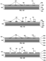
- a process begins by executing the steps described hereinabove with regard to FIGS. 11A-11E , to produce the pattern of geometric physiologically functional features 116 illustrated in FIG. 11E , except in this embodiment, the layer 114 of material is a sacrificial layer of material that is removed in a subsequent step.
- a layer 120 of material is deposited into spaces between the geometric physiologically functional features 116 by vacuum deposition.
- the layer 120 has a thickness essentially the same as that of the geometric physiologically functional features 116.
- the geometric physiologically functional features 116 of the sacrificial layer 114 are removed, for example, by chemical etching, photo etching, laser ablation, or other method reveal geometric physiologically functional features 122 patterned across the surface 104 of the implantable material 100.
- Each of the geometric physiologically functional features 122 is a recess that has a thickness or depth between a surface 124 of the layer 120 and the surface 104.
- the shape of the recesses 122 as seen looking in the direction of arrow 126 in FIG. 12B may be any of the shapes described for the geometric physiologically functional features including: circle, square, rectangle, triangle, polygonal, hexagonal, octagonal, elliptical, parallel lines and intersecting lines, or any combination thereof.
- the recesses 122 may have the width 112, or diameter if the recesses 122 are circular, in a range between about 1 nanometer and about 75 micrometers, alternatively between about 1 nanometer and about 50 micrometers, alternatively between about 1 nanometer and about 2000 nanometers, or alternatively between about 1 nanometer and about 200 nanometers.
- Adjacent recesses 122 may be spaced apart by the distance D in a range from about 1 nanometer to about 20 micrometers, from about 1 nanometer to about 10 micrometers, from about 1 nanometer to about 5 micrometers, or from about 1 nanometer to about 3 micrometers.
- the distance D may be less than, about equal to or greater than the width 112.
- the width 112 of each of the recesses 122 and/or the distance D between adjacent recesses 122 may vary in size to form a patterned array of the recesses 122.
- the recesses 122 having width and spacing as described hereinabove with regard to FIGS. 12A and 12B may be formed by machining the recesses 122 through a layer or layers 128 of vacuum deposited material.
- an implantable material 130 having a surface 132 may comprise a bulk material 134, the one or more layers 128 of vacuum deposited material, or the bulk material 134 and the one or more layers 128 of vacuum deposited material, as illustrated in FIG. 13A .
- the geometric physiologically functional features 116 themselves include a plurality of deposited layers, wherein the geometric physiologically functional features 116 include the first layer 102a, the second layer 102b, and the third layer 102c.
- the geometric physiologically functional features 116 are deposited through a mask as previously indicated, on top of structural material of the stent or other medical device include deposited layer 102d and 102e.
- the geometric physiologically functional features 116 include the first layer 102a and the second layer 102b, deposited through the mask whereby the structural material of the stent or other medical device includes the layers 102c-102d.
- the geometric physiologically functional features 116 include the first layer 102a, the second layer 102b, the third layer 102c, and the fourth layer 102d, whereby the structural material of the stent or other medical device includes the fifth layer 102e.
- the thickness of the layers as deposited can be modified to be a narrower or decreased thickness as to allow for the geometric physiologically functional feature 116 to be adjusted to a particular thickness.
- the layers of different vacuum deposited materials can be deposited to create the elevated surfaces having inherently different material properties.
- layers of the same vacuum deposited material can be deposited having differences in grain size, grain phase, and/or surface topography or variations of hydrophobic, hydrophilic or surface energy difference relative to the surface of the stent or structural material.
- the grain size, grain phase, and/or surface topography or variations of hydrophobic, hydrophilic or surface energy difference relative to the surface of the stent or structural material may be formed or included on the surface as shown in U.S. Patent Application Serial No. 12/428,981, which was filed April, 23, 2009 .
- the recesses 122 may include a plurality of layers 102 to provide for differences in grain size, grain phase, and/or surface topography or variations of hydrophobic, hydrophilic or surface energy difference relative to the surface of the stent or structural material.
- the recesses 122 may be formed by the surface 124 being deposited through a mask as to form the layer 120 that gives rise to the plurality of recesses 122 with a wall 123.
- the recesses 122 include an inner wall 123 including the first layer 102a, the second layer 102b, and the third layer 102c, whereby the surface 104 is on layer 102d, which is exposed on the bottom of the recess 122 and surface 124 is on top of layer 102a.
- the recesses 122 may include a wall of the first layer 102a and the second layer 102b, whereby the surfaces 124 are deposited through a mask, and the structural material of the stent or other medical device includes the layers 102d-102e.
- the recesses 122 include a wall of the first layer 102a, the second layer 102b, the third layer 102c, and the fourth layer 102d, and surfaces 124 are deposited through a mask whereby surface 102e that acts as the surface 104 of the structural material of the medical device.
- additional layers 102a-102d are included as the wall in the geometric physiologically functional feature 116, the thickness of the layers as deposited can be modified to be a narrower or decreased thickness as to allow for the geometric physiologically functional feature 116 to be adjusted to a particular thickness.
- the layers of different vacuum deposited materials can be deposited to create recesses having inherently different material properties.
- layers of the same vacuum deposited material can be deposited having differences in grain size, grain phase, and/or surface topography or variations of hydrophobic, hydrophilic or surface energy difference relative to the surface of the stent or structural material.
- recesses 136 may be machined into the surface 132 of the implantable material 130 to have a depth greater than a thickness of a first layer of material 128a or recesses 138 may be machined into the surface 132 of the implantable material 130 to have a depth greater than a thickness of the first and second layers 128a, 128b of material.
- Two layers are illustrated for convenience of explanation and illustration; however, any number of layers 128 of material may be used as desired or appropriate.
- each of the recesses 136 has a thickness or depth between the surface 132 of the layer 128a and a surface 140 that is within a second layer 128b.
- each of the recesses 138 has a thickness or depth between the surface 132 of the layer 128a and a surface 142 that is within the bulk material 134.
- An implantable material including geometric physiologically functional features comprising a layer or layers of vacuum deposited material, as illustrated by the geometric physiologically functional features 116 in FIG. 11E , recesses disposed through one or more layers of vacuum deposited material, as illustrated by the recesses 122 in FIG. 12B or the recesses 136 or 138 in FIG. 13B , has an inherently different structure than a block of material having recesses cut into it.
- the reason for this inherent difference lies in the differences in the materials making up surfaces exposed by the recesses. For example, in the case of a block of material and assuming that the block material is uniform in regard to material properties, an undisturbed surface of the block and a surface within a recess or groove cut into the block have the same material properties.
- layers of different vacuum deposited materials can be deposited to create recessed and/or elevated surfaces having inherently different material properties.
- layers of the same vacuum deposited material can be deposited having differences in grain size, grain phase, and/or surface topography.
- the alternative grain size, grain phase, and/or surface topography may be included or formed, by way of example, any of the methods disclosed in commonly assigned U.S. Patent Application No. 12/428,981, filed April, 23, 2009 .
- surfaces of the recesses 122, 136 can be deposited to have a roughened surface topography and a large grain size and surfaces of the material deposited defining the recesses 122, 136, for example the layer 120 illustrated in FIG. 12B , can have a relatively smoother surface topography and/or a smaller grain size.
- Alternative grain sizes and surfaces may be formed and included as shown in U.S. Patent Application Serial No. 12/428,981, which was filed April, 23, 2009 .
- a factor in increasing endothelialization of a surface of an implanted medical device may be the cleanliness of the surface.
- cleanliness refers to the presence or lack of contaminant molecules bonding to otherwise unsaturated chemical bonds at the surface.
- a perfectly clean surface for example as may exist in a vacuum, comprises unsaturated bonds at the surface that have not bound to any contaminant molecules. The unsaturated bonds provide the surface with a higher surface energy as compared to a contaminated surface having fewer unsaturated bonds, which have a lower surface energy. Measurements of surface energy may be accomplished by contact angle measurements, as disclosed in U.S. Patent Application Serial No. 12/428,981, which was filed April, 23, 2009 .
- unsaturated chemical bonds at the surface will bond to contaminant molecules when exposed thereto.
- air-borne chemistries such as phthalates, hydrocarbons, and even water that may bond to unsaturated bonds or otherwise attach to reactive spots such as, for example, residual negative charges on the surface of a metal oxide.
- Such contaminant molecules for example, normally occurring hydrocarbons, SO 2 , NO, etc., occupy otherwise unsaturated bonds thereby reducing the number of unsaturated bonds and lowering the surface energy of the surface. Such reduction in the number of unsaturated bonds decreases the availability of such unsaturated bonds for interaction with blood proteins.
- the air atmosphere around the surface include normally occurring impurities which will be attracted to the unsaturated chemical bonds at levels in the air around 1x10 9 to 1x10 6 so it will take a few seconds before the surface is contaminated by their Brownian motion, after 1 min, most of the unsaturated bond are saturated with contaminants.
- One molecular monolayer i.e. a single layer of molecules
- additional molecules may bond to the surface and build multi-layers of contaminant molecules.
- the surface of a few molecular monolayers of contaminants may have thickness of about 0.1-2 nm, which may be detected by sensitive surface analysis as indicated above.
- a cleaner surface having more unsaturated bonds provides increased potential for interaction with blood proteins. It is contemplated that a contaminated surface of a vacuum deposited or bulk material can be activated, or made more likely to interact with blood proteins, by removing the contaminant molecules that occupy the otherwise unsaturated bonds at the surface.
- plasma etching there may be several techniques for accomplishing such activation, including by way of example and not limitation, chemical etching, wet chemical etching, oxidation, electrochemical treatment, thermal treatment, UV-ozone cleaning, coating by evaporation or sputtering, etc.
- another technique for activating a vacuum deposited surface may be by using plasma electron bombardment under vacuum, a technique also known as plasma etching.
- the contaminant layer may be detected by surface-sensitive spectroscopies, such as Auger electron spectroscopy (AES), x-ray photoemission spectroscopy (XPS or ESC), infrared reflection absorption spectroscopy (IRAS, FT-IR, etc.) secondary ion mass spectroscopy (SIMS), and those disclosed in U.S. Patent Application Serial No. 12/428,981 .
- Plasma etching the sample to be treated is positioned within a controlled electrical gas discharge (a plasma), as schematically shown in FIG. 14 .
- the plasma may be formed by applying a high voltage (AC or DC) over a gas under considerably lower pressure than one atmosphere (typically 0.1-lmm Hg, or a vacuum). Because of the low pressure and because gas 0 purity is vital for the process, the discharge and the sample must be housed in a hermetically closed system that can be evacuated by vacuum pumps, and whose gas composition can be controlled.
- the plasma also has sufficient energy and momentum to remove atoms and molecules that are adsorbed on unsaturated bonds, or are constituents of the native surface.
- the contamination layer bond to unsaturated bonds may be removed, to recreate the 5 unsaturated bonds on the surface and thus increasing the surface energy.
- the surface treatment can be mild (mainly removal of the contamination layer) or more aggressive.
- the complete surface oxide layer on a metal may be removed so that the bare metal is exposed. The latter occurs only provided that no oxidizing or other reactive gases are present, i.e., the used gas must be a noble gas such as Ar, Kr, or Xe.
- the composition of the newly formed surface is controlled; if oxygen is added, oxide will be formed; if nitrogen or hydrocarbons are added, surface nitride or surface carbide, respectively, will form, etc.
- the gas purity must be high, as impurities within the gas will react to the high energy cleaned surfaces.
- the activated surface can be preserved by introducing a contaminant gas or liquid into the plasma etching process in a controlled manner, which may be easily removed before use of the medical device.
- the contaminant layer may be a known biodegradable material or may be a contaminant layer or coating of inorganic or organic nature or a mixture of both.
- the contaminant layer may be a layer readily removed by a saline or water solution, which are typically used in flushing procedures or washing procedures.
- the activated surface may also be coated with a protective coating of a biodegradable material that dissolves upon exposure to the in vivo environment when implanted.
- the biodegradable material may alternatively be dissolved via introduction of an externally delivered fluid solvent during implantation.
- the protective coating may be a fluid in which the activated device is immersed until implantation. For example, it is contemplated that storing the activated surface in water facilitates preservation of the activation as compared to exposure of the activated surface to air.
- the biodegradable material may be any material, natural or synthetic, that may be broken down by living organisms, including, but not limited to a biodegradable organic substance, biodegradable polymer substances (Poly(lactic acid) PLA, poly(L-lactic acid) (PLLA), poly(lactic-co-glycolic acid) PLGA, poly(glycolicacid) (PGA), Polyethylene glycol, PEG, polytetrafluoroethylene (PTFE), and the like), peptides or proteins, carbohydrates, nucleic acids, fatty acids, carbon-containing compounds, nanoparticles, microparticles, biocomposites, sol-gel coatings, hydrogels water-soluble bioactive agent and poly(alkyl cyanoacrylate) polymer coating; nanoparticle coating formed by electrospraying; a poly(diol citrates)-based coatings; natural biodegradable hydrophobic polysaccharides coatings, hydrophilic polymers, and the like.
- other materials may be used, such as gold, other
- the method disclosed herein comprehends the creation of a patterned array of geometric physiologically functional features elevated relative to a surface of an implantable biocompatible material, recessed relative to the surface, or disposed on the surface.
- the implantable biocompatible material is formed of a bulk material of titanium, nickel-titanium alloy or other titanium-rich alloy metals or a top most layer of titanium, nickel-titanium alloy or other titanium-rich alloy metals deposited over the bulk material.
- the titanium, nickel-titanium alloy or other titanium-rich alloy metal is oxidized to convert surface titanium to titanium dioxide, then covered with a pattern-mask and exposed to high intensity UV irradiation.
- TiO 2 titanium dioxide absorbs UV radiation and has been used in a variety of applications as a UV inhibitor to prevent UV transmission across a TiO 2 barrier layer. It has been discovered that upon exposure to UV irradiation, an originally hydrophobic and oleophilic titanium oxide layer becomes amphiphilic.
- the amphiphilic state of the UV irradiated titanium oxide may be advantageously employed as an alternative to depositing patterned elevated or recessed geometric physiologically functional features onto the implantable biocompatible material.
- An implantable biocompatible material fabricated having a bulk substrate or a top most vacuum deposited layer of titanium or a titanium alloy is masked with a pattern mask having a plurality of openings passing there through.
- the plurality of openings preferably have a size and special array selected to define affinity binding domains and cellular migration cites for promoting endothelial cell binding and proliferation across the substrate surface.
- the open surface area of each of the plurality of openings in the pattern mask is preferably in the range of between about 1nm to about 75 ⁇ m, and with adjacent pairs of openings being in a spaced apart relationship such that a distance of about 1 nm to about 75 ⁇ m exists between the openings, the inter-opening being greater than, about equal to, or less than the size of the opening.
- an implantable material 56 made of titanium or a titanium-alloy having at least one surface 52 and 54 that is oxidized by heating or an equivalent known by the person skilled in the art.
- a machined mask 48 that had laser-cut holes 40 of defined size from about 1 nm to about 75 ⁇ m, from about 1 nm to about 50 ⁇ m, from about 1 nm to about 2000 nm, and preferably from about 1 nm to about 200 nm, patterned throughout to coat the at least one surface 52 of the implantable material 56 and is tightly adhered to the covered surface 52.
- the implantable material 56 covered with the mask 48 is then illuminated by the ultraviolet rays. Because TiO 2 is sensitive to ultraviolet, the chemical composition in holes 58 is different from the area that is covered by the mask. In contrast to the geometric physiologically functional features illustrated in FIGS. 9C , 11E , 12B , and 13B , the geometric physiologically functional features 59 in FIG. 10C are not elevated and therefore have zero thickness relative to the surrounding surface of the implantable material.
- the mask is removed to reveal the surface 52 that surrounds the geometric physiologically functional features 59 formed by ultraviolet irradiation.
- the shape of the holes 58 in the mask 48 could be in any of the shapes described for the geometric physiologically functional features including: circle, square, rectangle, triangle, parallel lines and intersecting lines, and combinations thereof, the geometric physiologically functional features 59 accordingly adopts such shapes also.
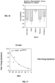
- Nickel-titanium sheets were heated to oxidize titanium present at the surface of the sheet.
- Pattern masks fabricated from machined metal were laser drilled a pattern of holes having diameters ranging from 15 ⁇ m to 50 ⁇ m, with a single diameter of holes on each pattern mask.
- a single pattern mask was placed over a single nickel-titanium sheet and the assembly was exposed to high intensity ultra-violet irradiation. After UV irradiation, the irradiated nickel-titanium sheet was placed on a fully endothelialized test surface and maintained at 37° C. under simulated in vivo flow conditions and under static flow conditions.
- contact angle measurements were performed using a VCA-2500XE video contact angle system (AST systems, Billerica, MA) on the flat metal pieces after cleaning as described above.
- the surface energy of all materials studied was determined by the advancing contact angle measurement of three standard liquids; water, formamide and xylene; on each metal surface and calculated by the harmonic mean method.
- Ten videocaptures per second of the advancing fluid droplet/solid interface were obtained for water and formamide and 65 captures per second for xylene. All experiments were repeated 4 times.
- Glow discharge plasma treatment is a method of cleaning and removing surface contaminants from metallic as well as other surfaces, schematically shown in FIG. 15 .
- Glow discharge treatment of many metallic surfaces causes their surfaces to change from very hydrophobic surfaces on which water beads to a hydrophilic surface on which water rapidly
Landscapes
- Health & Medical Sciences (AREA)
- Chemical & Material Sciences (AREA)
- Engineering & Computer Science (AREA)
- Life Sciences & Earth Sciences (AREA)
- Veterinary Medicine (AREA)
- General Health & Medical Sciences (AREA)
- Public Health (AREA)
- Animal Behavior & Ethology (AREA)
- Biomedical Technology (AREA)
- Vascular Medicine (AREA)
- Heart & Thoracic Surgery (AREA)
- Organic Chemistry (AREA)
- Chemical Kinetics & Catalysis (AREA)
- Cardiology (AREA)
- Transplantation (AREA)
- Oral & Maxillofacial Surgery (AREA)
- Metallurgy (AREA)
- Mechanical Engineering (AREA)
- Materials Engineering (AREA)
- Medicinal Chemistry (AREA)
- Epidemiology (AREA)
- Surgery (AREA)
- Molecular Biology (AREA)
- Physics & Mathematics (AREA)
- General Physics & Mathematics (AREA)
- Nuclear Medicine, Radiotherapy & Molecular Imaging (AREA)
- Pharmacology & Pharmacy (AREA)
- General Chemical & Material Sciences (AREA)
- Bioinformatics & Cheminformatics (AREA)
- Prostheses (AREA)
- Materials For Medical Uses (AREA)
Applications Claiming Priority (2)
| Application Number | Priority Date | Filing Date | Title |
|---|---|---|---|
| US13/107,510 US8679517B2 (en) | 2002-09-26 | 2011-05-13 | Implantable materials having engineered surfaces made by vacuum deposition and method of making same |
| PCT/US2012/037776 WO2012158614A2 (en) | 2011-05-13 | 2012-05-14 | Implantable materials having engineered surfaces and method of making same |
Publications (4)
| Publication Number | Publication Date |
|---|---|
| EP2707044A2 EP2707044A2 (en) | 2014-03-19 |
| EP2707044A4 EP2707044A4 (en) | 2014-10-29 |
| EP2707044B1 true EP2707044B1 (en) | 2025-06-04 |
| EP2707044C0 EP2707044C0 (en) | 2025-06-04 |
Family
ID=47177584
Family Applications (1)
| Application Number | Title | Priority Date | Filing Date |
|---|---|---|---|
| EP12786428.8A Active EP2707044B1 (en) | 2011-05-13 | 2012-05-14 | Implantable materials having engineered surfaces and method of making same |
Country Status (8)
| Country | Link |
|---|---|
| US (4) | US8679517B2 (enExample) |
| EP (1) | EP2707044B1 (enExample) |
| JP (1) | JP2014514127A (enExample) |
| CN (1) | CN103619364A (enExample) |
| AU (1) | AU2012255972B2 (enExample) |
| CA (1) | CA2835844C (enExample) |
| MX (1) | MX2013013139A (enExample) |
| WO (1) | WO2012158614A2 (enExample) |
Families Citing this family (20)
| Publication number | Priority date | Publication date | Assignee | Title |
|---|---|---|---|---|
| US8458879B2 (en) * | 2001-07-03 | 2013-06-11 | Advanced Bio Prosthetic Surfaces, Ltd., A Wholly Owned Subsidiary Of Palmaz Scientific, Inc. | Method of fabricating an implantable medical device |
| US8679517B2 (en) * | 2002-09-26 | 2014-03-25 | Palmaz Scientific, Inc. | Implantable materials having engineered surfaces made by vacuum deposition and method of making same |
| GB0724736D0 (en) | 2007-12-19 | 2008-01-30 | Oxford Nanolabs Ltd | Formation of layers of amphiphilic molecules |
| EP2422827B1 (en) * | 2010-08-27 | 2019-01-30 | Biotronik AG | Stent with a surface layer having a topographic modification |
| CH705978A1 (de) * | 2012-01-11 | 2013-07-15 | Qvanteq Ag | Verfahren und Vorrichtung zur Bestimmung einer Oberflächencharakteristik an Stents und Stent mit definierter Oberflächencharakteristik. |
| GB201202519D0 (en) * | 2012-02-13 | 2012-03-28 | Oxford Nanopore Tech Ltd | Apparatus for supporting an array of layers of amphiphilic molecules and method of forming an array of layers of amphiphilic molecules |
| GB201313121D0 (en) | 2013-07-23 | 2013-09-04 | Oxford Nanopore Tech Ltd | Array of volumes of polar medium |
| CN103861155A (zh) * | 2014-03-11 | 2014-06-18 | 郑欣 | 一种具有诱导细胞增殖分化能力的纳米形貌芯片 |
| US10687956B2 (en) | 2014-06-17 | 2020-06-23 | Titan Spine, Inc. | Corpectomy implants with roughened bioactive lateral surfaces |
| TWI726940B (zh) | 2015-11-20 | 2021-05-11 | 美商泰坦脊柱股份有限公司 | 積層製造整形外科植入物之方法 |
| GB201611770D0 (en) | 2016-07-06 | 2016-08-17 | Oxford Nanopore Tech | Microfluidic device |
| EP3493768A1 (en) | 2016-08-03 | 2019-06-12 | Titan Spine, Inc. | Implant surfaces that enhance osteoinduction |
| CN107789666A (zh) * | 2016-08-30 | 2018-03-13 | 北京航空航天大学 | 一种内壁微图案化小口径人造血管 |
| CN110366435A (zh) * | 2017-02-24 | 2019-10-22 | 扩凡科技有限公司 | 用于植入物的表面密封物 |
| US10373767B2 (en) | 2017-11-21 | 2019-08-06 | Vactronix Scientific, Llc | Structural supercapacitor composite and method of making same |
| GB2568895B (en) | 2017-11-29 | 2021-10-27 | Oxford Nanopore Tech Ltd | Microfluidic device |
| US11457932B2 (en) | 2018-03-15 | 2022-10-04 | Mako Surgical Corp. | Robotically controlled water jet cutting |
| KR20210138594A (ko) | 2019-03-12 | 2021-11-19 | 옥스포드 나노포어 테크놀로지즈 피엘씨 | 나노포어 감지 디바이스 및 이를 작동하는 방법 및 형성하는 방법 |
| CN111973814B (zh) * | 2019-05-21 | 2024-04-19 | 中国人民解放军军事科学院军事医学研究院 | 一种具有复合仿生界面的血管支架及其制备方法 |
| WO2022013551A1 (en) | 2020-07-17 | 2022-01-20 | Oxford Nanopore Technologies Limited | Nanopore sensing device |
Citations (3)
| Publication number | Priority date | Publication date | Assignee | Title |
|---|---|---|---|---|
| EP0606566A1 (en) * | 1992-12-07 | 1994-07-20 | Nobelpharma AB | Method for preparing implant surfaces |
| WO2008112458A2 (en) * | 2007-03-09 | 2008-09-18 | Icon Medical Corp | Bioabsorbable coatings for medical devices |
| US20080299337A1 (en) * | 2006-02-09 | 2008-12-04 | Isoflux, Inc. | Method for the formation of surfaces on the inside of medical devices |
Family Cites Families (98)
| Publication number | Priority date | Publication date | Assignee | Title |
|---|---|---|---|---|
| US5387247A (en) | 1983-10-25 | 1995-02-07 | Sorin Biomedia S.P.A. | Prosthetic device having a biocompatible carbon film thereon and a method of and apparatus for forming such device |
| US4657544A (en) | 1984-04-18 | 1987-04-14 | Cordis Corporation | Cardiovascular graft and method of forming same |
| WO1987005038A1 (en) | 1986-02-17 | 1987-08-27 | Commonwealth Scientific And Industrial Research Or | Implantable materials |
| IT1196836B (it) | 1986-12-12 | 1988-11-25 | Sorin Biomedica Spa | Protesi in materiale polimerico con rivestimento di carbonio biocompatibile |
| US5133845A (en) | 1986-12-12 | 1992-07-28 | Sorin Biomedica, S.P.A. | Method for making prosthesis of polymeric material coated with biocompatible carbon |
| US5079600A (en) | 1987-03-06 | 1992-01-07 | Schnur Joel M | High resolution patterning on solid substrates |
| US5588443A (en) | 1989-07-25 | 1996-12-31 | Smith & Nephew Richards, Inc. | Zirconium oxide and zirconium nitride coated guide wires |
| US5278063A (en) | 1989-09-28 | 1994-01-11 | Board Of Regents The University Of Texas System | Chemical modification of promote animal cell adhesion on surfaces |
| US5477864A (en) | 1989-12-21 | 1995-12-26 | Smith & Nephew Richards, Inc. | Cardiovascular guidewire of enhanced biocompatibility |
| US5207709A (en) | 1991-11-13 | 1993-05-04 | Picha George J | Implant with textured surface |
| CA2087132A1 (en) | 1992-01-31 | 1993-08-01 | Michael S. Williams | Stent capable of attachment within a body lumen |
| BE1006440A3 (fr) | 1992-12-21 | 1994-08-30 | Dereume Jean Pierre Georges Em | Endoprothese luminale et son procede de preparation. |
| US5607463A (en) | 1993-03-30 | 1997-03-04 | Medtronic, Inc. | Intravascular medical device |
| US5658443A (en) | 1993-07-23 | 1997-08-19 | Matsushita Electric Industrial Co., Ltd. | Biosensor and method for producing the same |
| US5645740A (en) | 1993-11-01 | 1997-07-08 | Naiman; Charles S. | System and assemblage for producing microtexturized substrates and implants |
| US20010039454A1 (en) | 1993-11-02 | 2001-11-08 | John Ricci | Orthopedic implants having ordered microgeometric surface patterns |
| EP0701803B1 (en) | 1994-02-03 | 1999-10-06 | SYNTHES AG Chur | Medical device for implantation into living bodies |
| US5733303A (en) | 1994-03-17 | 1998-03-31 | Medinol Ltd. | Flexible expandable stent |
| US5725573A (en) | 1994-03-29 | 1998-03-10 | Southwest Research Institute | Medical implants made of metal alloys bearing cohesive diamond like carbon coatings |
| JPH07284527A (ja) | 1994-04-18 | 1995-10-31 | Ishikawajima Harima Heavy Ind Co Ltd | 生体用金属およびその使用法 |
| DE4429380C1 (de) * | 1994-08-15 | 1996-04-25 | Biotronik Mess & Therapieg | Verfahren zur Herstellung einer nichtkollabierenden intravasalen Gefäßprothese (Stent) |
| US6774278B1 (en) * | 1995-06-07 | 2004-08-10 | Cook Incorporated | Coated implantable medical device |
| US5609629A (en) | 1995-06-07 | 1997-03-11 | Med Institute, Inc. | Coated implantable medical device |
| US5607475A (en) | 1995-08-22 | 1997-03-04 | Medtronic, Inc. | Biocompatible medical article and method |
| US6001622A (en) | 1995-12-21 | 1999-12-14 | Sunnybrook Health Science Centre | Integrin-linked kinase and its use |
| JPH09225021A (ja) | 1995-12-22 | 1997-09-02 | Toto Ltd | 医用材料 |
| US5843289A (en) | 1996-01-22 | 1998-12-01 | Etex Corporation | Surface modification of medical implants |
| NZ331269A (en) | 1996-04-10 | 2000-01-28 | Advanced Cardiovascular System | Expandable stent, its structural strength varying along its length |
| US5932299A (en) | 1996-04-23 | 1999-08-03 | Katoot; Mohammad W. | Method for modifying the surface of an object |
| US5769884A (en) | 1996-06-27 | 1998-06-23 | Cordis Corporation | Controlled porosity endovascular implant |
| US6007573A (en) | 1996-09-18 | 1999-12-28 | Microtherapeutics, Inc. | Intracranial stent and method of use |
| US5895419A (en) | 1996-09-30 | 1999-04-20 | St. Jude Medical, Inc. | Coated prosthetic cardiac device |
| IT1289815B1 (it) | 1996-12-30 | 1998-10-16 | Sorin Biomedica Cardio Spa | Stent per angioplastica e relativo procedimento di produzione |
| US5902475A (en) | 1997-04-08 | 1999-05-11 | Interventional Technologies, Inc. | Method for manufacturing a stent |
| US6240616B1 (en) | 1997-04-15 | 2001-06-05 | Advanced Cardiovascular Systems, Inc. | Method of manufacturing a medicated porous metal prosthesis |
| US5891507A (en) | 1997-07-28 | 1999-04-06 | Iowa-India Investments Company Limited | Process for coating a surface of a metallic stent |
| US5980564A (en) | 1997-08-01 | 1999-11-09 | Schneider (Usa) Inc. | Bioabsorbable implantable endoprosthesis with reservoir |
| US5897911A (en) | 1997-08-11 | 1999-04-27 | Advanced Cardiovascular Systems, Inc. | Polymer-coated stent structure |
| US6143370A (en) | 1997-08-27 | 2000-11-07 | Northeastern University | Process for producing polymer coatings with various porosities and surface areas |
| WO1999023977A1 (en) | 1997-11-07 | 1999-05-20 | Expandable Grafts Partnership | Intravascular stent and method for manufacturing an intravascular stent |
| US5955588A (en) | 1997-12-22 | 1999-09-21 | Innerdyne, Inc. | Non-thrombogenic coating composition and methods for using same |
| US6077413A (en) | 1998-02-06 | 2000-06-20 | The Cleveland Clinic Foundation | Method of making a radioactive stent |
| US6140127A (en) | 1998-02-18 | 2000-10-31 | Cordis Corporation | Method of coating an intravascular stent with an endothelial cell adhesive five amino acid peptide |
| US6280467B1 (en) | 1998-02-26 | 2001-08-28 | World Medical Manufacturing Corporation | Delivery system for deployment and endovascular assembly of a multi-stage stented graft |
| US6103320A (en) | 1998-03-05 | 2000-08-15 | Shincron Co., Ltd. | Method for forming a thin film of a metal compound by vacuum deposition |
| JP3735461B2 (ja) | 1998-03-27 | 2006-01-18 | 株式会社シンクロン | 複合金属の化合物薄膜形成方法及びその薄膜形成装置 |
| DE19916086B4 (de) | 1998-04-11 | 2004-11-11 | Inflow Dynamics Inc. | Implantierbare Prothese, insbesondere Gefäßprothese (Stent) |
| US6261322B1 (en) | 1998-05-14 | 2001-07-17 | Hayes Medical, Inc. | Implant with composite coating |
| US6086773A (en) | 1998-05-22 | 2000-07-11 | Bmc Industries, Inc. | Method and apparatus for etching-manufacture of cylindrical elements |
| US6387060B1 (en) | 1998-06-17 | 2002-05-14 | Advanced Cardiovascular Systems, Inc. | Composite radiopaque intracorporeal product |
| US6096175A (en) | 1998-07-17 | 2000-08-01 | Micro Therapeutics, Inc. | Thin film stent |
| US6159239A (en) | 1998-08-14 | 2000-12-12 | Prodesco, Inc. | Woven stent/graft structure |
| MXPA01003283A (es) | 1998-09-30 | 2002-07-02 | Impra Inc | Mecanismo de suministro para un dispositivo de stent implantable. |
| US6325825B1 (en) | 1999-04-08 | 2001-12-04 | Cordis Corporation | Stent with variable wall thickness |
| US6253441B1 (en) | 1999-04-16 | 2001-07-03 | General Electric Company | Fabrication of articles having a coating deposited through a mask |
| US6258121B1 (en) | 1999-07-02 | 2001-07-10 | Scimed Life Systems, Inc. | Stent coating |
| US6334868B1 (en) | 1999-10-08 | 2002-01-01 | Advanced Cardiovascular Systems, Inc. | Stent cover |
| US7300457B2 (en) | 1999-11-19 | 2007-11-27 | Advanced Bio Prosthetic Surfaces, Ltd. | Self-supporting metallic implantable grafts, compliant implantable medical devices and methods of making same |
| US6936066B2 (en) | 1999-11-19 | 2005-08-30 | Advanced Bio Prosthetic Surfaces, Ltd. | Complaint implantable medical devices and methods of making same |
| US6537310B1 (en) | 1999-11-19 | 2003-03-25 | Advanced Bio Prosthetic Surfaces, Ltd. | Endoluminal implantable devices and method of making same |
| US6379383B1 (en) | 1999-11-19 | 2002-04-30 | Advanced Bio Prosthetic Surfaces, Ltd. | Endoluminal device exhibiting improved endothelialization and method of manufacture thereof |
| US6849085B2 (en) | 1999-11-19 | 2005-02-01 | Advanced Bio Prosthetic Surfaces, Ltd. | Self-supporting laminated films, structural materials and medical devices manufactured therefrom and method of making same |
| US6533905B2 (en) | 2000-01-24 | 2003-03-18 | Tini Alloy Company | Method for sputtering tini shape-memory alloys |
| KR100860860B1 (ko) | 2000-03-15 | 2008-09-29 | 오르버스네이치 메디칼 인코포레이티드 | 내피 세포 부착을 촉진하는 코팅 |
| US6183255B1 (en) | 2000-03-27 | 2001-02-06 | Yoshiki Oshida | Titanium material implants |
| JP4955849B2 (ja) | 2000-04-06 | 2012-06-20 | 健 八尾 | アパタイト構造体、及びアパタイトパターン形成方法 |
| WO2001076525A2 (en) | 2000-04-10 | 2001-10-18 | Advanced Cardiovascular Systems, Inc. | Selectively coated stent delivery system and method of manufacture thereof |
| WO2001087371A2 (en) | 2000-05-12 | 2001-11-22 | Advanced Bio Prosthetic Surfaces, Ltd. | Self-supporting laminated films, structural materials and medical devices |
| DE60124772T2 (de) | 2000-05-19 | 2007-09-13 | Advanced Bio Prothestic Surfaces, Ltd., San Antonio | Verfahren und vorrichtung zur herstellung eines intravaskulären stents |
| US8632583B2 (en) * | 2011-05-09 | 2014-01-21 | Palmaz Scientific, Inc. | Implantable medical device having enhanced endothelial migration features and methods of making the same |
| US6652579B1 (en) | 2000-06-22 | 2003-11-25 | Advanced Cardiovascular Systems, Inc. | Radiopaque stent |
| JP2002017847A (ja) | 2000-07-03 | 2002-01-22 | Kikuji Yamashita | 細胞外マトリックス結合型生体融和材料およびその製造方法、細胞外マトリックス製剤およびその製造方法 |
| US6569194B1 (en) | 2000-12-28 | 2003-05-27 | Advanced Cardiovascular Systems, Inc. | Thermoelastic and superelastic Ni-Ti-W alloy |
| JP3598973B2 (ja) | 2001-01-10 | 2004-12-08 | ソニー株式会社 | 利得可変回路 |
| US6767360B1 (en) * | 2001-02-08 | 2004-07-27 | Inflow Dynamics Inc. | Vascular stent with composite structure for magnetic reasonance imaging capabilities |
| DE60104647T2 (de) | 2001-03-27 | 2005-08-11 | William Cook Europe Aps | Gefässtransplantat für die Aorta |
| US6527938B2 (en) | 2001-06-21 | 2003-03-04 | Syntheon, Llc | Method for microporous surface modification of implantable metallic medical articles |
| US6444318B1 (en) | 2001-07-17 | 2002-09-03 | Surmodics, Inc. | Self assembling monolayer compositions |
| US6746890B2 (en) | 2002-07-17 | 2004-06-08 | Tini Alloy Company | Three dimensional thin film devices and methods of fabrication |
| CA2499976C (en) * | 2002-09-26 | 2013-06-11 | Advanced Bio Prosthetic Surfaces, Ltd. | Implantable materials having engineered surfaces and method of making same |
| US8679517B2 (en) * | 2002-09-26 | 2014-03-25 | Palmaz Scientific, Inc. | Implantable materials having engineered surfaces made by vacuum deposition and method of making same |
| US8268340B2 (en) | 2002-09-26 | 2012-09-18 | Advanced Bio Prosthetic Surfaces, Ltd. | Implantable materials having engineered surfaces and method of making same |
| US8715771B2 (en) | 2003-02-26 | 2014-05-06 | Abbott Cardiovascular Systems Inc. | Coated stent and method of making the same |
| US8281737B2 (en) | 2003-03-10 | 2012-10-09 | Boston Scientific Scimed, Inc. | Coated medical device and method for manufacturing the same |
| DE602004024053D1 (de) | 2003-05-07 | 2009-12-24 | Advanced Bio Prothestic Surfac | Metallische implantierbare prothesen und herstellungsverfahren dafür |
| US20050055085A1 (en) | 2003-09-04 | 2005-03-10 | Rivron Nicolas C. | Implantable medical devices having recesses |
| US7296998B2 (en) | 2003-09-22 | 2007-11-20 | Bartee Chaddick M | Hydrophilic high density PTFE medical barrier |
| US20050119723A1 (en) | 2003-11-28 | 2005-06-02 | Medlogics Device Corporation | Medical device with porous surface containing bioerodable bioactive composites and related methods |
| US8715340B2 (en) | 2004-03-31 | 2014-05-06 | Merlin Md Pte Ltd. | Endovascular device with membrane |
| CN101193666A (zh) * | 2005-04-26 | 2008-06-04 | 奥胡斯大学 | 用于外科植入和引导细胞之组织培养表面的生物相容性材料 |
| WO2007108373A1 (ja) | 2006-03-17 | 2007-09-27 | Kinki University | 生体親和性透明シート、その製造方法、及び細胞シート |
| US8110242B2 (en) | 2006-03-24 | 2012-02-07 | Zimmer, Inc. | Methods of preparing hydrogel coatings |
| US8080055B2 (en) | 2006-12-28 | 2011-12-20 | Boston Scientific Scimed, Inc. | Bioerodible endoprostheses and methods of making the same |
| US7753962B2 (en) | 2007-01-30 | 2010-07-13 | Medtronic Vascular, Inc. | Textured medical devices |
| WO2009015420A1 (en) * | 2007-07-27 | 2009-02-05 | The University Of Sydney | Biological functionalisation of substrates |
| DE102009023371A1 (de) | 2009-05-29 | 2010-12-02 | Acandis Gmbh & Co. Kg | Verfahren zur Herstellung eines medizinischen Funktionselements mit einer freitragenden Gitterstruktur |
| US9186267B2 (en) | 2012-10-31 | 2015-11-17 | Covidien Lp | Wing bifurcation reconstruction device |
| US20140128901A1 (en) | 2012-11-05 | 2014-05-08 | Kevin Kang | Implant for aneurysm treatment |
-
2011
- 2011-05-13 US US13/107,510 patent/US8679517B2/en not_active Expired - Lifetime
-
2012
- 2012-05-14 CN CN201280031581.4A patent/CN103619364A/zh active Pending
- 2012-05-14 MX MX2013013139A patent/MX2013013139A/es unknown
- 2012-05-14 JP JP2014510536A patent/JP2014514127A/ja active Pending
- 2012-05-14 WO PCT/US2012/037776 patent/WO2012158614A2/en not_active Ceased
- 2012-05-14 EP EP12786428.8A patent/EP2707044B1/en active Active
- 2012-05-14 AU AU2012255972A patent/AU2012255972B2/en active Active
- 2012-05-14 CA CA2835844A patent/CA2835844C/en active Active
-
2014
- 2014-03-19 US US14/219,924 patent/US9272077B2/en not_active Expired - Lifetime
-
2016
- 2016-03-01 US US15/057,986 patent/US10039866B2/en not_active Expired - Lifetime
-
2018
- 2018-07-31 US US16/050,088 patent/US10729824B2/en not_active Expired - Lifetime
Patent Citations (3)
| Publication number | Priority date | Publication date | Assignee | Title |
|---|---|---|---|---|
| EP0606566A1 (en) * | 1992-12-07 | 1994-07-20 | Nobelpharma AB | Method for preparing implant surfaces |
| US20080299337A1 (en) * | 2006-02-09 | 2008-12-04 | Isoflux, Inc. | Method for the formation of surfaces on the inside of medical devices |
| WO2008112458A2 (en) * | 2007-03-09 | 2008-09-18 | Icon Medical Corp | Bioabsorbable coatings for medical devices |
Non-Patent Citations (1)
| Title |
|---|
| R E BAIER ET AL: "Implant surface preparation", THE INTERNATIONAL JOURNAL OF ORAL & MAXILLOFACIAL IMPLANTS, 1 January 1988 (1988-01-01), United States, pages 9 - 20, XP055507761, Retrieved from the Internet <URL:https://www.researchgate.net/profile/Robert_Baier/publication/20081239_Implant_surface_preparation/links/579f2d1f08ae5d5e1e176b0b/Implant-surface-preparation.pdf?origin=publication_detail> [retrieved on 20180918] * |
Also Published As
| Publication number | Publication date |
|---|---|
| US10729824B2 (en) | 2020-08-04 |
| MX2013013139A (es) | 2014-05-27 |
| CA2835844C (en) | 2023-11-07 |
| US20140294910A1 (en) | 2014-10-02 |
| CN103619364A (zh) | 2014-03-05 |
| CA2835844A1 (en) | 2012-11-22 |
| US20110274737A1 (en) | 2011-11-10 |
| AU2012255972A1 (en) | 2014-01-16 |
| US20190038815A1 (en) | 2019-02-07 |
| WO2012158614A2 (en) | 2012-11-22 |
| US10039866B2 (en) | 2018-08-07 |
| EP2707044A2 (en) | 2014-03-19 |
| WO2012158614A3 (en) | 2013-01-10 |
| US8679517B2 (en) | 2014-03-25 |
| EP2707044C0 (en) | 2025-06-04 |
| US20170028109A1 (en) | 2017-02-02 |
| JP2014514127A (ja) | 2014-06-19 |
| AU2012255972B2 (en) | 2016-06-23 |
| EP2707044A4 (en) | 2014-10-29 |
| US9272077B2 (en) | 2016-03-01 |
Similar Documents
| Publication | Publication Date | Title |
|---|---|---|
| EP2707044B1 (en) | Implantable materials having engineered surfaces and method of making same | |
| US10682443B2 (en) | Implantable biomaterials having functional surfaces | |
| Variola et al. | Improving biocompatibility of implantable metals by nanoscale modification of surfaces: an overview of strategies, fabrication methods, and challenges | |
| CA2835485C (en) | Implantable medical device having enhanced endothelial migration features and methods of making the same | |
| US20090118821A1 (en) | Endoprosthesis with porous reservoir and non-polymer diffusion layer | |
| KR101666672B1 (ko) | 선택적 플라즈마 에칭을 이용하여 표면에 중금속 함유 나노구조물이 형성된 합금 기재의 제조방법 및 이의 용도 |
Legal Events
| Date | Code | Title | Description |
|---|---|---|---|
| PUAI | Public reference made under article 153(3) epc to a published international application that has entered the european phase |
Free format text: ORIGINAL CODE: 0009012 |
|
| 17P | Request for examination filed |
Effective date: 20131212 |
|
| AK | Designated contracting states |
Kind code of ref document: A2 Designated state(s): AL AT BE BG CH CY CZ DE DK EE ES FI FR GB GR HR HU IE IS IT LI LT LU LV MC MK MT NL NO PL PT RO RS SE SI SK SM TR |
|
| DAX | Request for extension of the european patent (deleted) | ||
| A4 | Supplementary search report drawn up and despatched |
Effective date: 20141001 |
|
| RIC1 | Information provided on ipc code assigned before grant |
Ipc: A61L 27/44 20060101ALI20140926BHEP Ipc: A61F 2/01 20060101ALI20140926BHEP Ipc: A61L 27/40 20060101AFI20140926BHEP |
|
| 17Q | First examination report despatched |
Effective date: 20151218 |
|
| STAA | Information on the status of an ep patent application or granted ep patent |
Free format text: STATUS: EXAMINATION IS IN PROGRESS |
|
| GRAP | Despatch of communication of intention to grant a patent |
Free format text: ORIGINAL CODE: EPIDOSNIGR1 |
|
| STAA | Information on the status of an ep patent application or granted ep patent |
Free format text: STATUS: GRANT OF PATENT IS INTENDED |
|
| INTG | Intention to grant announced |
Effective date: 20250107 |
|
| GRAS | Grant fee paid |
Free format text: ORIGINAL CODE: EPIDOSNIGR3 |
|
| GRAA | (expected) grant |
Free format text: ORIGINAL CODE: 0009210 |
|
| STAA | Information on the status of an ep patent application or granted ep patent |
Free format text: STATUS: THE PATENT HAS BEEN GRANTED |
|
| RAP1 | Party data changed (applicant data changed or rights of an application transferred) |
Owner name: VACTRONIX SCIENTIFIC, LLC |
|
| AK | Designated contracting states |
Kind code of ref document: B1 Designated state(s): AL AT BE BG CH CY CZ DE DK EE ES FI FR GB GR HR HU IE IS IT LI LT LU LV MC MK MT NL NO PL PT RO RS SE SI SK SM TR |
|
| REG | Reference to a national code |
Ref country code: GB Ref legal event code: FG4D |
|
| REG | Reference to a national code |
Ref country code: CH Ref legal event code: EP |
|
| REG | Reference to a national code |
Ref country code: DE Ref legal event code: R096 Ref document number: 602012081549 Country of ref document: DE |
|
| REG | Reference to a national code |
Ref country code: IE Ref legal event code: FG4D |
|
| U01 | Request for unitary effect filed |
Effective date: 20250703 |
|
| U07 | Unitary effect registered |
Designated state(s): AT BE BG DE DK EE FI FR IT LT LU LV MT NL PT RO SE SI Effective date: 20250709 |
|
| PG25 | Lapsed in a contracting state [announced via postgrant information from national office to epo] |
Ref country code: ES Free format text: LAPSE BECAUSE OF FAILURE TO SUBMIT A TRANSLATION OF THE DESCRIPTION OR TO PAY THE FEE WITHIN THE PRESCRIBED TIME-LIMIT Effective date: 20250604 |
|
| PG25 | Lapsed in a contracting state [announced via postgrant information from national office to epo] |
Ref country code: NO Free format text: LAPSE BECAUSE OF FAILURE TO SUBMIT A TRANSLATION OF THE DESCRIPTION OR TO PAY THE FEE WITHIN THE PRESCRIBED TIME-LIMIT Effective date: 20250904 Ref country code: GR Free format text: LAPSE BECAUSE OF FAILURE TO SUBMIT A TRANSLATION OF THE DESCRIPTION OR TO PAY THE FEE WITHIN THE PRESCRIBED TIME-LIMIT Effective date: 20250905 |
|
| PG25 | Lapsed in a contracting state [announced via postgrant information from national office to epo] |
Ref country code: PL Free format text: LAPSE BECAUSE OF FAILURE TO SUBMIT A TRANSLATION OF THE DESCRIPTION OR TO PAY THE FEE WITHIN THE PRESCRIBED TIME-LIMIT Effective date: 20250604 |
|
| PG25 | Lapsed in a contracting state [announced via postgrant information from national office to epo] |
Ref country code: HR Free format text: LAPSE BECAUSE OF FAILURE TO SUBMIT A TRANSLATION OF THE DESCRIPTION OR TO PAY THE FEE WITHIN THE PRESCRIBED TIME-LIMIT Effective date: 20250604 |
|
| PG25 | Lapsed in a contracting state [announced via postgrant information from national office to epo] |
Ref country code: RS Free format text: LAPSE BECAUSE OF FAILURE TO SUBMIT A TRANSLATION OF THE DESCRIPTION OR TO PAY THE FEE WITHIN THE PRESCRIBED TIME-LIMIT Effective date: 20250904 |