EP2705935A1 - Machine de mesure de coordonnées - Google Patents
Machine de mesure de coordonnées Download PDFInfo
- Publication number
- EP2705935A1 EP2705935A1 EP12183806.4A EP12183806A EP2705935A1 EP 2705935 A1 EP2705935 A1 EP 2705935A1 EP 12183806 A EP12183806 A EP 12183806A EP 2705935 A1 EP2705935 A1 EP 2705935A1
- Authority
- EP
- European Patent Office
- Prior art keywords
- camera
- target object
- unit
- end effector
- measuring machine
- Prior art date
- Legal status (The legal status is an assumption and is not a legal conclusion. Google has not performed a legal analysis and makes no representation as to the accuracy of the status listed.)
- Withdrawn
Links
Images


Classifications
-
- G—PHYSICS
- G01—MEASURING; TESTING
- G01B—MEASURING LENGTH, THICKNESS OR SIMILAR LINEAR DIMENSIONS; MEASURING ANGLES; MEASURING AREAS; MEASURING IRREGULARITIES OF SURFACES OR CONTOURS
- G01B11/00—Measuring arrangements characterised by the use of optical techniques
- G01B11/002—Measuring arrangements characterised by the use of optical techniques for measuring two or more coordinates
- G01B11/005—Measuring arrangements characterised by the use of optical techniques for measuring two or more coordinates coordinate measuring machines
-
- G—PHYSICS
- G01—MEASURING; TESTING
- G01B—MEASURING LENGTH, THICKNESS OR SIMILAR LINEAR DIMENSIONS; MEASURING ANGLES; MEASURING AREAS; MEASURING IRREGULARITIES OF SURFACES OR CONTOURS
- G01B5/00—Measuring arrangements characterised by the use of mechanical techniques
- G01B5/0002—Arrangements for supporting, fixing or guiding the measuring instrument or the object to be measured
- G01B5/0004—Supports
-
- B—PERFORMING OPERATIONS; TRANSPORTING
- B25—HAND TOOLS; PORTABLE POWER-DRIVEN TOOLS; MANIPULATORS
- B25J—MANIPULATORS; CHAMBERS PROVIDED WITH MANIPULATION DEVICES
- B25J9/00—Programme-controlled manipulators
- B25J9/16—Programme controls
- B25J9/1615—Programme controls characterised by special kind of manipulator, e.g. planar, scara, gantry, cantilever, space, closed chain, passive/active joints and tendon driven manipulators
- B25J9/1623—Parallel manipulator, Stewart platform, links are attached to a common base and to a common platform, plate which is moved parallel to the base
-
- B—PERFORMING OPERATIONS; TRANSPORTING
- B25—HAND TOOLS; PORTABLE POWER-DRIVEN TOOLS; MANIPULATORS
- B25J—MANIPULATORS; CHAMBERS PROVIDED WITH MANIPULATION DEVICES
- B25J9/00—Programme-controlled manipulators
- B25J9/16—Programme controls
- B25J9/1694—Programme controls characterised by use of sensors other than normal servo-feedback from position, speed or acceleration sensors, perception control, multi-sensor controlled systems, sensor fusion
- B25J9/1697—Vision controlled systems
-
- G—PHYSICS
- G05—CONTROLLING; REGULATING
- G05B—CONTROL OR REGULATING SYSTEMS IN GENERAL; FUNCTIONAL ELEMENTS OF SUCH SYSTEMS; MONITORING OR TESTING ARRANGEMENTS FOR SUCH SYSTEMS OR ELEMENTS
- G05B2219/00—Program-control systems
- G05B2219/30—Nc systems
- G05B2219/39—Robotics, robotics to robotics hand
- G05B2219/39052—Self calibration of parallel manipulators
Definitions
- the present invention relates to a coordinate measuring machine according to claim 1, and a method for gauging a target object by using such a coordinate measuring machine according to claim 17.
- a coordinate measuring machine has a tactile probe or an optical probe for gauging the surface of a target object.
- the optical or tactile probe is movable fixed at an articulated arm, as it is shown for a tactile probe i.e. in EP 2283311 A1 , or at a portal, as it is shown for an optical probe i.e. in WO 2008/135530 A1 , so that it can be moved over the surface of the target object.
- the CMM usually has to be calibrated by means of a reference object and a program has to be written defining the trajectories for the measurement probes.
- measuring with an optical probe instead of a tactile probe in general can increase the measurement rate and avoid abrasion effects at the surface of the target object.
- Another option to increase measurement rate is the use of a camera as a measurement probe and using this camera in an "on the fly"-mode, as it is described in WO 2008/135530 A1 .
- the camera is moved continuously over the target object and takes pictures only at the interesting positions without stopping there.
- the position data for each image is delivered from the position encoders and stored together with the according image.
- a flash light illumination of the interesting positions ensures a sharp picture in spite of the moving speed of the camera. As the camera is not stopped at the interesting positions, less deceleration and acceleration actions have to be carried out which decreases measuring time.
- a Delta Robot is a type of parallel robot. It comprises a stationary base fixed at a stationary frame, which is mounted above a workspace, and three middle jointed arms extending from the base.
- the arms often called kinematic chains, are connected with their first end to the base by means of universal joints and connected with their second end to an end effector often built in form of a triangular or circular platform.
- the arms are made of lightweight composite material and are driven by actuators located in the base. Actuation can be done with linear or rotational actuators.
- the arms are made of a light composite material the moving parts of the delta robot have a small inertia. This allows for very high accelerations and very fast movement, which outclasses by far those realizable by a portal machine or an articulated arm.
- the key design feature of a Delta Robot is the use of parallelograms in the arms, which maintains the orientation of the end effector by restricting the movement of the end effector to pure translation (movement only with 3 degrees of freedom (3DOF: translation in the x-, y- or z-direction).
- Delta Robots are mainly used for gripping and placing items, wherein the gripper is arranged at the end effector.
- the movement of the end effector and precise gripping and placing of items is controlled by a main controller getting feedback information of the actuators and of angle encoders connected to the joints of the arms often named position encoders.
- a trajectory of the end effector from a position an item has to be gripped to a position where the item has to be placed is stored in the main controller.
- the main controller controls the actuators of the arms in a way that the end effector follows the programmed trajectory.
- Delta Robots and machines based on a Delta Robot were popular for picking and packaging in factories of the packaging industry, medical and pharmaceutical industry; some executing up to 300 picks per minute.
- Other possible applications include assembly tasks or operation in clean rooms for electronic components as well as haptic interfaces controlling medical or industrial robotic systems for enabling human operators to operate instinctively and safely critical systems.
- Delta Robots have been found so far not suitable for measurement requirements. This is because of their sensitivity to temperature fluctuation and strong vibration during fast movement and fast acceleration/deceleration actions, caused by their lightweight construction. As a result, the exact position of the end effector can not be determined precisely enough and adequate focusing with optical means, e.g. an optical probe for a CMM or a camera, is not possible.
- optical means e.g. an optical probe for a CMM or a camera
- the CMM disclosed in this brochure is again only be able to measure the target object with reference to a reference object, which has to be measured before the target object of a series production can be measured. That means it has to be calibrated before the measurement. So, no cut down of measurement time is possible during preparation of the measurement and only special trained persons will be able to handle this CMM.
- Object of the presented invention is therefore a coordinate measuring machine which is user-friendly, reasonably priced and very fast.
- the named objects are solved by a coordinate measuring machine according to one or more of the independent claims or according to the independent claim(s) in combination with one or more of the dependent claims.
- a coordinate measuring machine (CMM) presented here comprises a Delta Robot as a support structure.
- the Delta Robot having an end effector at the free end of its kinematic chains movable within a motion zone.
- a tool-holder fixed to the end effector is configured to accommodate various measurement probes.
- the measurement probe is movable by means of the end effector within the motion zone over a target object, wherein the motion of the end effector is controlled by a control unit.
- An analysing unit of the CMM is configured for processing electronic signals and/or data delivered by the measurement probe.
- the measurement probe is a camera.
- signals or data delivered by the measurement probe are images taken by said camera, wherein the camera comprising an optics having a field of view encompassing maximum 20% of the motion zone.
- the analysing unit comprises storage means for storing said images and comprises a circuit unit for processing said images.
- the control system is configured to move the camera over the target object in an "on the fly"-mode.
- the camera has optics with a field of view encompassing maximum 20% of the motion zone, the camera can be built with a very low inertial mass and can deliver images of high quality. Further such a camera is cost-efficient and therefore the whole CMM can reasonable be priced.
- the combination of a Delta Robot as a support structure with such a camera and a control unit configured for moving the camera in an "on the fly”-mode allows a high speed movement and high acceleration and deceleration actions of the camera.
- large target objects can be measured very quickly thanks to high speed movement; small target object can be measured very fast as well, thanks to the high acceleration/deceleration actions that allows for occurring the many changes in movement direction rapidly.
- the CMM is provided with output means in form of a display or monitor and optionally a loud speaker for acoustic warning connected to the analysing unit for presenting the results to the user. Further as known there is an input means for enabling the user to manipulate the CMM.
- Those means can be integrated in the CMM as presented here e.g. in the stationary base or they can be built as an external unit or integrated in a computer that is connected to the CMM by wire or wireless in well known manner.
- the circuit of the analysing unit is configured to generate a realistic sight of the target object, which had been gauged or is gauging by the camera. That means the analysing unit is capable for carrying out image processing after gauging is accomplished or during gauging.
- the information content of the realistic sight is selectable by the user.
- the circuit thereby generates the realistic sight with the selected information content by means of adding the according information of the images in an overlapping or handshaking way. Creating a realistic sight of the gauged target object only considering the selected information reduces processing time for processing the images delivered from the camera.
- the camera is a high speed camera being able to take pictures/images very fast, that means with more than 360 frames per second (fps), wherein the illumination of the target object is ensured by a light source configured for illuminating the object in a stroboscopic way at each time a picture is taken.
- the stroboscopic illumination ensures sharp images in spite of the fast movement of the camera.
- the light source is part of the CMM and can be arranged in a way that the part of the target object, from which a picture should be taken by the camera, is illuminated from the side the camera looks at it or - in case only the contour of the object is of interest - from behind the object.
- the light source is arranged at the end effector together with the camera.
- the camera in particular is controlled in a way for taking pictures with a high clock rate, e.g. with 500 fps or more, and the stroboscopic illumination is coordinated with this clock rate, so that the target object is illuminated each time a picture is taken.
- the clock rate is preferably adaptable to the current speed of the camera motion and to the field of view of the camera, so that the analysing unit is able to create a realistic sight out of the according information of the taken images by overlapping or handshaking without having to many images and by that increasing processing time and without having not enough images for handshaking/overlapping.
- the Delta Robot of the CMM has as usual a stationary base fixed at a stationary frame and comprises kinematic chains, which are middle jointed arms, that means a first part of the arm is jointed to a second part of the arm by a joint.
- the arms are connected by joints with their first parts to the stationary base and with their second parts by joints to the end effector.
- the joints can be provided with angle encoders, also called position sensors, in order to deliver according angle signals, so that the current position of the end effector with the camera can be derived and used by the analysing unit and the control unit.
- the end effector supports a sensor unit, wherein the sensor unit comprises multi axis acceleration sensors measuring acceleration and deceleration of the measurement probe in direction of the horizontal x-axis and/or the horizontal y-axis and/or the vertical z-axis.
- the sensor unit comprises multi axis acceleration sensors measuring acceleration and deceleration of the measurement probe in direction of the horizontal x-axis and/or the horizontal y-axis and/or the vertical z-axis.
- Another option is to provide tilt sensors for the horizontal x-axis and y-axis in the sensor unit of the end effector in order to determine the current position of the camera more precisely.
- a gyroscope in form of a gyrostat, MEMS (Micro ElectroMechanical System), VSG (Vibrating Structure Gyroscope) or other known embodiments can be integrated in the sensor unit.
- an IMU Inertial Measurement Unit integrating accelerometers and gyroscopes and optionally magnetometers is included in the sensor unit.
- the global surveillance system comprises at least one stationary camera and at least one marking in the region of the end effector, wherein region of the end effector comprises the end effector and/or the tool-holder and/or the camera.
- the marking and the stationary camera of the global surveillance system are arranged relative to one another in a way that the marking is visible by the stationary camera during at least 80% of the measuring time.
- the easiest way to arrange the stationary camera of the global surveillance system is fixing the stationary camera at the stationary base or the stationary frame of the Delta Robot.
- the stationary frame thereby is constructed in a relative massive way with a high moment of inertia, so that the movement of the kinematic chains with the end effector and the measurement probe does not have any impact on the stationary frame.
- the stationary cameras can have a field of few encompassing the whole motion zone of the end effector and by that the whole volume occupied by the target object in this zone.
- cameras having a field of view of 100% or more of the motion zone are usable, but usually more expensive as cameras having a smaller field view. Therefore cameras with a smaller field of view, in the range of 60% up to 80% of the filed of view, are sufficient and allows decreasing the costs.
- Three and more cameras can better ensure that the marking(s) are always visible during the measurement at least by one camera.
- too many cameras increase the data to be processed for determining the position and therefore an optimisation between number of cameras and data processing time has to be found.
- the field of view of the cameras should be overlapping in the centre of the motion zone or one camera is focused on the centre region of the motion zone and is overlapping with the fields of view of the "outer" cameras arranged with their fields of view equally around the field of view of the "centre" camera.
- the number of markings is at least one but better two, more preferred three, seven or ten, wherein markings of the global surveillance system can be arranged not only in the region of the end effector, which is at the end effector and/or at the tool-holder and/or at the camera but can also be arranged in the region of the second parts of the arms.
- the markings should be arranged in such a distance to each other that they are well distinguishable on the pictures taken by the camera(s).
- the markings of the global surveillance system should be amply dimensioned, so that they are well visible in the pictures taken. That means a marking should be represented by more than one pixel better four or nine pixels or even more pixels depending on the resolution. However, the dimension of the markings must ensure that they are recognizable at the pictures and their existence or non-existence/disappearance from one picture to the following picture should be unambiguously determinable.
- the global surveillance system comprises only one camera there should be seven or more markings; having two stationary cameras for stereo view, there should be fife or more markings, although it will work with three markings also; having three stationary cameras or more, three markings are fine, although more markings are better.
- the Delta Robot having no angle encoders but having a global surveillance system as described above and optionally the tilt sensors for the horizontal x-axis and y-axis and/or the multi axis acceleration sensors and/or an IMU as described above.
- angle encoders in the Delta Robot structure makes the Delta Robot structure cheaper and by that the CMM as a whole. Further it reduces the data to be processed in order to determine the current position of the measurement probe, which is an advantage with respect to processing time and electronic equipment.
- the analysing unit and/or the control unit is configured to derive position information by means of sensor fusion.
- the data generated by the global surveillance system and/or generated by one or more sensors of the sensor unit are processed.
- the signals/data of angle encoders of the delta structure can be processed together with those other signals/data by sensor fusing.
- the analysing unit and/or the control unit are configured to carry out sensor fusion by means of Kalman filters or similar instruments in order to increase the processing speed further.
- the analysing unit and/or the control unit are deriving position information from the sensor unit and/or the angle encoders and/or the global surveillance system with a system clock rate.
- the clock rate the images are taken by the camera is adaptable to said system clock rate, so that for each taken image an accurate position can be given.
- adaptable means the clock rate, images are taken, can be synchronized with the system clock rate, so that each time a position information derives from or is delivered by the sensor unit and/or the angle encoders and/or the global surveillance system, an image is been taken; or the clock rate, images are taken, is coordinated with the clock rate in a way that images are taken only each second or third time or with another defined ratio with respect to a derived or delivered position information.
- the control unit is configured as a high performance servo control system with a high control rate.
- the very fast control enabled by the high performance servo control system allow for making the control stiffer and thus more accurate. It further enables more complex control concepts such as state variable control loop and/or dual-loop control, and it enables integration of a high bandwidth, which facilitates a high clock rate of the process.
- the CMM is provided with a distance measurement unit determining the distance between the camera optics and the surface of the target object in order to ensure appropriate focusing.
- the same distance measurement unit can be used to determining the dimensions of the target.
- the distance measurement system is preferably located at the end effector and is moved together with the camera.
- the distance measurement unit is a laser distance measurement unit configured for determine the distance between the optics of the camera and an area of the surface of the target object, where the upcoming picture shall be taken, so that the distance determination is accomplished always before the camera is moved to said area.
- the correct focusing with respect to the distance between optics of the camera and the surface of the target object can be ensured during moving the camera to the said area by either adopting the distance by a movement in z-direction or by adopting the camera optics to an amended distance.
- the determination of the distance can be easily achieved in dependence of the motion speed and clock rate without a huge effort in data processing or programming.
- the camera can be moved in the motion zone with 6 dimensions of freedom. That can be realized by constructing the tool-holder in a way that tools, like the camera can be moved pivotable around the x-axis, y-axis and z-axis or by connecting the tool-holder to the end effector in a way that the tool-holder can be moved pivotable around the x-axis, y-axis and z-axis. Still another option to achieve this is using a Delta Robot like structure as they are known from medical applications; e.g. delta.6® from "force dimension", wherein the end effector can not only be moved in lateral dimensions by the middle jointed arms, but can be pivoted as well.
- a Delta Robot like structure as they are known from medical applications; e.g. delta.6® from "force dimension", wherein the end effector can not only be moved in lateral dimensions by the middle jointed arms, but can be pivoted as well.
- the Delta Robot can be described as having a stationary frame supporting a stationary base.
- the stationary base supports three middle joint arms carrying an end effector with a tool-holder movable with minimum 3 dimensions of freedom and with up to 6 dimensions of freedom.
- the end effector supports a sensor unit.
- the sensor unit comprises multi axis acceleration sensors and/or gyroscopes and or tilt sensors and or IMUs and/or at least three markings to be followed by at least two stationary cameras fixed to the stationary frame or stationary base.
- the tool-holder at the end effector of the Delta Robot is configured to accommodate further tools, like cameras with another field of view or another frame rate, optical measurement probes or tactile measurement probes or other tools, like a laser writer for metals, a drill or cutter head et ceterea.
- the tool-holder can be configured for allowing interchanging those probes and tools and can be provided with an adapter automatically recognizing the probe or tool fixed in the tool holder and by doing so starting the according program for running.
- the tool-holder further can be formed for accommodating a camera as described above at the end effector and adjacent to a probe or tool as described. The camera thereby can be arranged in a way that the probe or tool is within the field of view of the camera, so that it can be watched by the camera.
- the CMM as described above with the camera as a measurement probe can be used, e.g. to give a rough analysis of the target object as a preparation of a subsequent measurement with either the same or another camera, an optical or tactile probe or another tool.
- the preparation can include: ensuring the target object is on the table; ensuring the target object is correctly fixed with the correct span tools; checking, if there are possible obstacles that could cause collisions during measurement execution; finding the program, already stored, that must be used for measurement (auto-detection of the target object to be measured); automatically generating and executing a new program for measuring the main features, without any programming task for the user; getting sufficient information to align the target object and avoid the usual manual steps for alignment; measuring in pallets: that means multiple measurements of the same target object with unknown orientation or of different target objects, e.g. assembled in a support, with unknown orientation and possible unknown number of units.
- the measurement probe is the distance measurement unit configured to deliver data for a three dimensional point cloud (3D point cloud), while the analysing unit is configured to derive the 3D point cloud from said data, so that the spatial surface of the target object can be presented by the 3D point cloud.
- 3D point cloud three dimensional point cloud
- the distance measurement unit comprises a line or array receiving sensor. It is moved in an "on-the fly"-mode over the target object preferably scanning the surface of the target object.
- the laser comprises an optical component configured in a way that the pulsed laser beam can scan the target object along a first line, e.g. in x-direction.
- the whole target object can be scanned by moving the distance measurement by means of the end effector over the whole target object not using that optical component in its scan function or it can be scanned by moving the laser distance measurement unit along a second line, e.g. perpendicular to the first line e.g. in y-direction, while the scanner laser sends its pulses along the first line in x-direction.
- a receiving sensor integrated in the laser distance measurement unit is configured as a line or array sensor preferably intensity sensitive for the incoming reflecting pulses, like e.g. a CCD line or array sensor connected to the analysing unit.
- the camera at the end effector can also be used for delivering data for a 3D point cloud, by taking at least two images from different positions, which images are overlapping to at least 50 %, and by configuring the analysing unit with according software to derive a 3D point cloud out of those images as it is known in the field of stereo photogrammetry.
- the camera takes the images from different positions perpendicular from above the target object (CMM with 3DOF) or the camera takes the pictures from above the target object under different angles (CMM with 6DOF).
- the mentioned global surveillance system also can be used to generate data, which are delivered to the analysing unit for deriving a 3D point cloud, as, in some embodiments, 2 or more cameras are available for this purpose. As mentioned, those cameras are oriented to see the marking in the region of the end effector, what also brings the target object in the field of view.
- only one stationary camera belonging to the global surveillance system and the camera arranged at the end effector are provided and the analysing unit is configured to derive a 3D point cloud.
- the camera at the end effector is moved by the end effector into a position that a stereo view with the stationary camera results of an interesting portion of the target object or of the whole target object.
- the data generated by the stationary camera and the camera at the end effector are than delivered to the analysing unit and are processed by the analysing unit for deriving a 3D point cloud.
- the preparation for a measurement with an optical probe or a tactile probe is much faster using the new CMM with the camera as described above, as no programming and no calibration is necessary.
- the use of this CMM is possible for non-trained users also, as no programming steps are necessary: the necessary program being automatically identified or automatically newly programmed. Further, there is no need for a large optics to get the full sight of the target object, which makes the CMM very cost efficient.
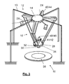
- Figure 1 shows a coordinate measuring machine CMM 10 according to the invention having a Delta Robot 12 as a supporting structure.
- the Delta Robot 12 comprises a stationary frame 13 supporting a stationary base 14, and three arms 16, also called kinematic chains.
- the frame 13 is usually a massive construction, but presented here filigree and only schematic in order to show details of the Delta Robot more clearly.
- the Delta Robot is shown without the stationary frame 13 in more details.
- Each arm has two parts 18, 20, which are linked by a middle joint 22.
- the first part 18 of each arm 16 is connected by first joints 24 to the stationary base 14 and with their second parts 20 by second joints 26 to an end effector 28.
- the end effector in this case is built in form of a circle like plate supporting a tool or measurement probe 30', here in form of a camera 30 accommodated in a tool-holder 31, a distance measurement unit 32 and a light source 34 for illuminating a target object 35, which can be placed at a workspace 36 beneath the end effector 28.
- the tool-holder 31 is configured in a way that the tool or measurement probes, 30, 30' are interchangeable.
- the end effector 28 supports a sensor unit 41 comprising a multi acceleration sensor 42 measuring the acceleration/ deceleration actions in horizontal x- and y-directions and in vertical z-direction.
- an IMU can be included in the sensor unit. However, this is more important in embodiments having six degrees of freedom (see below).
- a control unit 38 and an analysing unit 40 are arranged in the stationary base 14 of the Delta Robot 12.
- the analysing unit 40 can be located externally in a computer as well, which can be connected to the Delta Robot 12 by wired or wireless communication means (not shown).
- the joints are provided with angle encoders (not shown) in order to deliver according angle signals, so that the current position of the end effector 28 with the camera 30 can be derived and used by the analysing unit 40 and the control unit 38.
- the control unit 38 controls the movement of the end effector 28 with the camera 30 within the motion zone having 3 degrees of freedom (lateral in x-, y-, z-directions) by means of actuators (not shown) in a known manner by using the signals/data delivered by the angle encoders and in this example by additionally using the signal/data delivered by the multi acceleration sensor 42.
- actuators not shown
- the CMM 10 is, as known in the state of the art, provided with input means (not shown) and with output means (not shown), e.g. in form of a display or monitor and optionally a loud speaker for acoustic warning connected to the analysing unit 40 for presenting the results to the user. Further as known there is an input means for enabling the user to manipulate the CMM 10. Those means can be integrated in the CMM 10, e.g. in the stationary base 14 or they can be built as an external unit (not shown) or integrated in a computer (not shown) and connected to the CMM 10 by wire or wireless in well known manner.
- the camera In order to gauge a target object 35 the camera is moved with high speed over the target object and at the interesting positions a picture is taken, whereby illumination with the stroboscopic light with high intensity for a very short time ensures obtaining sharp images in spite of the movement speed. Further, focusing with respect to the distance between the camera optics and the surface to be measured is ensured by determining this distance by means of the distance measurement unit 32, which in this case is a laser distance measurement system based on triangulation.
- the CMM will work without the distance measurement unit 32 as well, especially if the target objects are knowingly of a geometry without grater discontinuations in the surface to be gauged. For such applications a cheaper CMM of this type without distance measurement unit will be sufficient.
- the images are delivered to the analysing unit 40 in the stationary base 14 of the CMM 10 together with the belonging position information derived from the angle encoder signals and the accelerations sensor signals. Than the images are processed in the analysing unit 40, so that a realistic sight of the target object 35 results with the information content the user had selected before.
- This information can be, e.g. only pixels having a colour within a distinct range of nano-meters, or pixels having an intensity over or under a distinct threshold, or within a specific intensity range, or image sections showing a specific contrast difference, or image sections along predetermined geometries, e.g. along the outer contour of a target object and further more.
- the camera 30 at the end effector 28 can also be used for delivering data for a 3D point cloud of a part of the target object 35, e.g. by taking at least two images from different positions perpendicular from above the target object 35, which images are overlapping to at least 50 %, or of the whole target object by taking pictures of the whole target object, which images overlapping to at least 50 %, and by configuring the analysing unit 40 with according software to derive a 3D point cloud out of those images as it is known in the field of stereo photogrammetry.
- the measurement probe is the distance measurement unit 32 configured to deliver data for a three dimensional point cloud, wherein the 3D point cloud e.g. can be derived from said data by the analysing unit 40, so that the spatial surface of the target object 35 can be presented by the 3D point cloud.
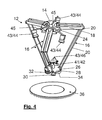
- FIGS 3 and 4 a further embodiment of the CMM is shown.
- this CMM is built analogue to the one shown in figures 1 and 2 , but additional to the angle encoders and the acceleration sensor 43 in the sensor unit 41 this CMM is provided with a global surveillance system 43.
- the global surveillance system 43 comprises three stationary cameras 44 fixed at cantilevers 45 which are supported by the stationary base 14.
- the cantilevers 45 could of course also be fixed at the stationary frame 13.
- the global surveillance system 43 comprises further markings 46 which are arranged in the region of the end effector 28/camera 30/sensor unit 41. In this example there are especially fife markings 46 fixed on top of the sensor unit 41.
- the markings 46 and the cameras 44 are arranged relatively to each other in a way that each marking 46 is visible at minimum during 80% of the measurement time by at least one camera 44.
- the stationary cameras 44 each have a field of view encompassing 70% of the motion zone of the end effector 28.
- the cantilevers 45 can be adjusted in their length in telescopic way and the cameras 44 are fixed by means of universal joints (not shown) to the cantilevers 45.
- Using the global surveillance system 43 eliminates the inaccuracy of the measurement caused by mechanical clearances and thermal fluctuations.
- the camera 30 in this example is a high speed camera able to take more than 500 frames per second (fps) and having a resolution e.g. of between 400'000 and 4'200'000 pixels by image dimensions in the range of 437'664 pixels 752x568 to 4'194'304 pixels 2048x2048, especially 1'048'576 pixels 1024x1024.
- fps frames per second
- the camera 30 can be moved over the target object with a constant speed of e.g. 0.5m-1m per second. Pictures are taken by the camera 30 with a high clock rate, whereby the illumination by means of the light source 34 is controlled to illuminate the surface of the target object 35 with the same clock rate, so that each image will be optimally illuminated. Measuring accelerations and consideration information of the global surveillance system 43 for determining the position of the measuring probe 30 allows the position determination of the measuring probe 30 with high accuracy even at higher measuring frequencies.
- FIG 5 is a CMM 10 shown very similar to that in figures 3 and 4 .
- the camera 30 can be moved in the motion zone with 6 degrees of freedom (DOF), as the end effector 28 can be tilted by an according control of the movement of the arms 16.
- DOF degrees of freedom
- Another option to realize 6 DOF of the camera 30 would be to fix the camera 30 within the tool-holder 31 pivotable or to connect the tool-holder 31 accommodating the camera 30 to the end effector 28 with a universal joint (not shown).
- the tilts or pivot motion of the tool-holder 31 or the camera 30 would be controlled by the control unit 31 and actuated by actuators as it is well known.
- the 6 DOF of the camera 30 enables a camera view not only perpendicular from the top but from various angles at the target object and from the sides at side surfaces of the target object.
- the camera 30 at the end effector 28 of this CMM 10 can also be used for generating realistic sights of the target object with selected information content, but as mentioned not only from the top but also from the sides of the target object. Further this camera 30 can also be used for delivering data for a 3D point cloud, as it has been described above, but in this case the images can be taken under different angles from above and from the different sides of the target object 35.
- the distance measurement unit 32 can be used for generating data that can be processed by the analysing unit 40 for deriving a 3D point could.
- the laser distance measurement unit 32 comprises an intensity sensitive line or array sensor (not shown) for receiving the reflected laser pulses.
- the laser distance measurement unit 32 can be moved in an "on-the fly"-mode over the target object or it can be pivoted by means of the end effector 28 in a way that the transmitted laser pulses are scanning the target object 35 along a first line e.g. in x-direction and synchronously be moved by means of the end effector 28 along a perpendicular second line, e.g. in y-direction.
- the global surveillance system 43 in this example has four stationary cameras 44 which are fixed with universal joints at the stationary frame 13.
- the stationary cameras 44 are fixed movable along the frame columns 50 and/or the frame cross beams 52.
- the Delta Robot 12 has no angle encoders connected to the joints 22, 24, 26, but additionally to the multi acceleration sensor 42 there are tilt sensors 48 integrated in the sensor unit 41 measuring the tilt of the end effector 28 and the camera 30 respectively in horizontal x- and y-direction.
- tilt sensors 48 for measuring tilt around the horizontal x-axis and y-axis allows determining of the current position of the camera more precisely.
- this embodiment is provided with an IMU included in the sensor unit.
- the control unit 38 in the embodiment is configured as a high performance servo control system with an extremely high control rate typically much more than 1 kHz and up to 200 kHz and the possibility of dual-loop control or state variables control loops.
- the arms 16 preferably are controlled by an axis servo control (not shown), which enables an axis control of the arms 16 with an extremely high control rate associated with a high control stiffness.
- the control unit 38 controls in connection with the axis servo control a high-precision motion trajectory using, e.g. model-based dual-loop control and/or a state variable control loop.
- the control unit 38 uses position information that have been derived by means of data fusion, preferably by means of a Kalman filters, using the data generated by the global surveillance system 43 and at least the acceleration data determined for the end effector 28.
- the chosen concept of high performance-control electronic with extremely high control clock rate and model-based dual-loop control enables an extremely dynamic trajectorie system.
- the axis servo-controls enable an axis control with extremely high control clock rate of up to 200 kHz associated with a high stiffness of the controler loop.
- the main control system in connection with the axis servo-controls controls the high-precision movement trajectory using model-based dual-loop and the absolute position information derived from the set up surveillance system and local acceleration data by means of sensor fusion e.g. by means of Kalman filters.
- the camera 30 In order to gauge a target object with this coordinate measuring machine 10 the camera 30 is moved in a "on the fly"-mode over an target object with high speed and high acceleration and deceleration actions as enabled by the Delta Robot structure 12. During the camera 30 movement pictures are taken by the camera 30 from the target object preferably with a constant, high clock rate. The target object is illuminated each time a picture is taken, by using the light source 34 with a stroboscopic light flashing having the same clock rate as the camera 30 for picture taking.
- the Laser distance measurement unit 32 determines the distance between the optics of the camera 30 and the surface of the target object preferably in dependence of the motion speed of the camera 30 and the clock rate of taking pictures for each immediately upcoming position where a picture shall be taken.
- the focus of the optics of the camera 30 is than adapted to the determined distance either by moving the camera 30 in vertical z-direction, so that the distance between the surface and optics of the camera 30 are maintained constant, or by adapting the optics of the camera 30 to the determined distance.
- Data processing is realized similar as described above, but the position determination is realized by carrying out sensor fusion - using the signals/data delivered from the global surveillance system 43 and the various sensors 42, 48 of the sensor unit 41 - preferably by means of Kalman filters or similar instruments - in order to increase the processing speed.
- the pictures are processed by overlapping or handshaking the taken pictures in order to generate a realistic sight of the whole target object; wherein handshaking means an overlapping of adjacent images by 3% to 6%; overlapping means an overlapping of the images by 8% to 15% unless in special processes, like for generating 3D point clouds (see above), where overlapping can be up to 50%.
- handshaking means an overlapping of adjacent images by 3% to 6%
- overlapping means an overlapping of the images by 8% to 15% unless in special processes, like for generating 3D point clouds (see above), where overlapping can be up to 50%.
- this method can be used as a measuring method per se or before gauging the target object with respect to other information not derivable from the taken images, in order to check the correct position and fixation of the target object and/or obstacles in the trajectories of the measurement probe 30' or in order to program trajectories for the measurement probe.
- the camera 30 can be disassembled from the tool-holder 31 and substitute by another tool 30', like a tactile or optical probe or other tool.
- Using an according interface in the tool-holder 31 and adapted to an information interface of the tool allows an automatic recognition of the tool, so that automatically suitable software is provided in the analysing unit 40 and the control unit 38.
- the three arms 16 of the Delta Robot 12 has angle encoders as already known in the state of the art.
- the signals of said encoders are used by the analysing unit and the control unit, respectively for determining the position of the end effector 28.
- the Delta Robot 12 having the sensor unit 41 at the end effector 28 and the global surveillance system 43 works perfectly without having those angle encoders. Creating a Delta Robot structure 12 without angle encoders makes the structure cheaper and may reduce data processing. But, having a Delta Robot having angle encoders and a sensor unit 41 and/or a global surveillance system 43 can use the information of all the systems to more precisely determine the position of the end effector 28 and the tool in the tool-holder 31.
- a simpler and cheaper type of an inventive CMM working without a distance measurement unit 32 can be fully sufficient.
- a global surveillance system may take over at least partially the function of the distance measurement unit, by analysing the images taking from the target object in relation to the end effector/camera and their position especially with respect to z-direction, also it might be less accurate.
- the invention provides an absolute measuring system with 3 to 6 degrees of freedom. It is able to determine the absolute position and orientation of the measurement probe with high accuracy and speed.
- the direct spatial determination of the absolute position and orientation of the measuring probe by means of the global surveillance system makes a complex calibration of the machine unnecessary, which reduces costs.
- the global surveillance system the influences from mechanical variations and thermal effects are eliminated to a great extend.
- the direct measurement of the position of the measuring camera removes all unwanted mechanical and thermal influences and thus allows a less expensive construction for the mechanical design of conventional coordinate measuring machines:
Priority Applications (5)
| Application Number | Priority Date | Filing Date | Title |
|---|---|---|---|
| EP12183806.4A EP2705935A1 (fr) | 2012-09-11 | 2012-09-11 | Machine de mesure de coordonnées |
| CN201380046549.8A CN104602870B (zh) | 2012-09-11 | 2013-09-09 | 坐标测量机器 |
| PCT/EP2013/068563 WO2014040937A1 (fr) | 2012-09-11 | 2013-09-09 | Machine de mesure de coordonnées |
| US14/427,280 US10107618B2 (en) | 2012-09-11 | 2013-09-09 | Coordinate measuring machine |
| EP13759217.6A EP2895304B1 (fr) | 2012-09-11 | 2013-09-09 | Machine de mesure de coordonnées |
Applications Claiming Priority (1)
| Application Number | Priority Date | Filing Date | Title |
|---|---|---|---|
| EP12183806.4A EP2705935A1 (fr) | 2012-09-11 | 2012-09-11 | Machine de mesure de coordonnées |
Publications (1)
| Publication Number | Publication Date |
|---|---|
| EP2705935A1 true EP2705935A1 (fr) | 2014-03-12 |
Family
ID=46851842
Family Applications (2)
| Application Number | Title | Priority Date | Filing Date |
|---|---|---|---|
| EP12183806.4A Withdrawn EP2705935A1 (fr) | 2012-09-11 | 2012-09-11 | Machine de mesure de coordonnées |
| EP13759217.6A Active EP2895304B1 (fr) | 2012-09-11 | 2013-09-09 | Machine de mesure de coordonnées |
Family Applications After (1)
| Application Number | Title | Priority Date | Filing Date |
|---|---|---|---|
| EP13759217.6A Active EP2895304B1 (fr) | 2012-09-11 | 2013-09-09 | Machine de mesure de coordonnées |
Country Status (4)
| Country | Link |
|---|---|
| US (1) | US10107618B2 (fr) |
| EP (2) | EP2705935A1 (fr) |
| CN (1) | CN104602870B (fr) |
| WO (1) | WO2014040937A1 (fr) |
Cited By (14)
| Publication number | Priority date | Publication date | Assignee | Title |
|---|---|---|---|---|
| CN105841576A (zh) * | 2015-02-04 | 2016-08-10 | 赫克斯冈技术中心 | 坐标测量机 |
| DE102015204796A1 (de) * | 2015-03-17 | 2016-09-22 | Carl Zeiss Industrielle Messtechnik Gmbh | Koordinatenmessgerät mit beweglichem Sensorträger und Positionsbestimmungseinrichtung, sowie Verfahren zum Betreiben eines Koordinatenmessgeräts |
| EP3081345A3 (fr) * | 2015-04-17 | 2016-12-07 | KUKA Systems GmbH | Systeme d'automatisation adaptatif pour verification de composant |
| EP3203179A1 (fr) * | 2016-02-05 | 2017-08-09 | Hexagon Technology Center GmbH | Machine de mesure basée sur un ensemble robot delta |
| US9803966B2 (en) | 2013-12-20 | 2017-10-31 | Hexagon Technology Center Gmbh | Coordinate measuring machine having high-precision 3-D printing functionality |
| CN109877814A (zh) * | 2019-04-26 | 2019-06-14 | 孙健春 | 一种并联驱动式全自动搬运机器人 |
| EP3502611A1 (fr) | 2017-12-21 | 2019-06-26 | Hexagon Technology Center GmbH | Surveillance de la géométrie de machines |
| US10401144B2 (en) | 2011-12-06 | 2019-09-03 | Hexagon Technology Center Gmbh | Coordinate measuring machine having a camera |
| GB2580224A (en) * | 2017-10-13 | 2020-07-15 | Renishaw Plc | Coordinate positioning machine |
| US10816335B2 (en) | 2015-08-05 | 2020-10-27 | Renishaw Plc | Coordinate positioning machine |
| US10967502B2 (en) | 2017-10-13 | 2021-04-06 | Renishaw Plc | Coordinate positioning machine |
| JPWO2021161950A1 (fr) * | 2020-02-12 | 2021-08-19 | ||
| US11543230B2 (en) * | 2019-06-07 | 2023-01-03 | Carl Zeiss Industrielle Messtechnik Gmbh | Articulating probe |
| US11624603B2 (en) | 2019-04-12 | 2023-04-11 | Renishaw Plc | Coordinate positioning machine |
Families Citing this family (40)
| Publication number | Priority date | Publication date | Assignee | Title |
|---|---|---|---|---|
| JP6284771B2 (ja) * | 2013-01-29 | 2018-02-28 | 株式会社ミツトヨ | パラレル機構 |
| US9261356B2 (en) * | 2014-07-03 | 2016-02-16 | Align Technology, Inc. | Confocal surface topography measurement with fixed focal positions |
| US9731392B2 (en) * | 2014-08-05 | 2017-08-15 | Ati Industrial Automation, Inc. | Robotic tool changer alignment modules |
| US9964398B2 (en) * | 2015-05-06 | 2018-05-08 | Faro Technologies, Inc. | Three-dimensional measuring device removably coupled to robotic arm on motorized mobile platform |
| KR20160143034A (ko) * | 2015-06-04 | 2016-12-14 | 한화테크윈 주식회사 | 델타 로봇 캘리브레이션 방법 및 델타 로봇 캘리브레이션 장치 |
| CN105758297B (zh) * | 2015-08-24 | 2018-02-02 | 江苏理工学院 | 并联机构式坐标测量装置 |
| CN108398081A (zh) * | 2015-08-24 | 2018-08-14 | 江苏理工学院 | 高温锻件测量系统 |
| EP3151554A1 (fr) * | 2015-09-30 | 2017-04-05 | Calay Venture S.a.r.l. | Caméra de présence |
| WO2017070872A1 (fr) * | 2015-10-28 | 2017-05-04 | 西门子公司 | Procédé et appareil de détection d'anomalie |
| CN105856200A (zh) * | 2016-05-25 | 2016-08-17 | 刘明月 | 一种新能源汽车轮毂抓取工业机器人用抓取装置 |
| CN108161948B (zh) * | 2016-06-23 | 2021-09-21 | 南京紫江电子技术有限公司 | 一种机器人 |
| EP3485112B1 (fr) | 2016-07-15 | 2021-08-25 | Fastbrick IP Pty Ltd | Véhicule qui incorpore une machine à poser les briques |
| BR112019000722B1 (pt) | 2016-07-15 | 2023-03-28 | Fastbrick Ip Pty Ltd | Lança extensível telescópica para transportar item e lança dobrável |
| CN106767599A (zh) * | 2016-12-26 | 2017-05-31 | 沈阳航空航天大学 | 一种三坐标测量装置及方法 |
| WO2018133964A1 (fr) | 2017-01-18 | 2018-07-26 | Siemens Wind Power A/S | Agencement de plateforme standardisée d'une éolienne |
| JP2018185251A (ja) * | 2017-04-27 | 2018-11-22 | セイコーエプソン株式会社 | ロボットおよびプリンター |
| WO2019006511A1 (fr) | 2017-07-05 | 2019-01-10 | Fastbrick Ip Pty Ltd | Dispositif de suivi de position et d'orientation en temps réel |
| EP3669138B1 (fr) | 2017-08-17 | 2023-05-24 | Fastbrick IP Pty Ltd | Dispositif de poursuite laser à mesure d'angle de roulis améliorée |
| CN111213098B (zh) | 2017-08-17 | 2024-03-15 | 快砖知识产权私人有限公司 | 用于交互系统的通信系统 |
| EP3680072B1 (fr) * | 2017-09-08 | 2024-05-01 | NTN Corporation | Dispositif de travail utilisant un mécanisme à liaison parallèle |
| JP6568172B2 (ja) * | 2017-09-22 | 2019-08-28 | ファナック株式会社 | キャリブレーションを行うロボット制御装置、計測システム及びキャリブレーション方法 |
| AU2018348785A1 (en) | 2017-10-11 | 2020-05-07 | Fastbrick Ip Pty Ltd | Machine for conveying objects and multi-bay carousel for use therewith |
| AT520613A1 (de) * | 2017-11-13 | 2019-05-15 | Voestalpine Tubulars Gmbh & Co Kg | Vorrichtung zur optischen Vermessung des Außengewinde-Profils von Rohren |
| SE543130C2 (en) | 2018-04-22 | 2020-10-13 | Zenrobotics Oy | A waste sorting robot gripper |
| US10830889B2 (en) | 2018-05-02 | 2020-11-10 | Faro Technologies, Inc. | System measuring 3D coordinates and method thereof |
| SE544741C2 (en) * | 2018-05-11 | 2022-11-01 | Genie Ind Bv | Waste Sorting Gantry Robot and associated method |
| DE102018111473B4 (de) * | 2018-05-14 | 2022-01-13 | Trumpf Laser- Und Systemtechnik Gmbh | Verfahren und Erfassungseinrichtung zur Ermittlung der Konturtreue einer kinematischen Baugruppe |
| CN108825971A (zh) * | 2018-06-14 | 2018-11-16 | 江苏盛矽电子科技有限公司 | 一种弹性定位式印刷网版的检版机 |
| US11073373B2 (en) * | 2018-08-22 | 2021-07-27 | Government Of The United States Of America, As Represented By The Secretary Of Commerce | Non-contact coordinate measuring machine using a noncontact metrology probe |
| CN109848987B (zh) * | 2019-01-22 | 2022-02-01 | 天津大学 | 一种并联机器人视觉伺服控制方法 |
| JP7228290B2 (ja) * | 2019-02-25 | 2023-02-24 | 国立大学法人 東京大学 | ロボットシステム、ロボットの制御装置、およびロボットの制御プログラム |
| CN110231010B (zh) * | 2019-04-26 | 2021-07-13 | 合肥工业大学 | 一种基于Delta并联机构的三坐标测量机及测量方法 |
| DE102019122655A1 (de) | 2019-08-22 | 2021-02-25 | M & H Inprocess Messtechnik Gmbh | Messsystem |
| CN110716504B (zh) * | 2019-10-21 | 2022-06-14 | 同济大学 | 一种基于多闭环串级控制的滚球系统运动控制方法 |
| KR20210052090A (ko) * | 2019-10-31 | 2021-05-10 | 삼성전자주식회사 | 증강 현실 장치 |
| US11524410B2 (en) * | 2020-06-12 | 2022-12-13 | Hexagon Metrology, Inc. | Robotic alignment method for workpiece measuring systems |
| CN112959326B (zh) * | 2021-03-29 | 2022-06-07 | 深圳市优必选科技股份有限公司 | 机器人正运动学求解方法、装置、可读存储介质及机器人 |
| CN113787519B (zh) * | 2021-09-08 | 2022-12-06 | 伯朗特机器人股份有限公司 | 基于完整动力学模型的delta型并联机器人设计方法 |
| CN116135479A (zh) | 2021-11-17 | 2023-05-19 | 通用汽车环球科技运作有限责任公司 | 用于自动和/或协同紧固操作的六自由度和三自由度机器人系统 |
| CN116331986B (zh) * | 2023-04-03 | 2023-11-24 | 河北智立云智能科技有限公司 | 一种基于物联网的电梯智能监管配套设备及实施方法 |
Citations (2)
| Publication number | Priority date | Publication date | Assignee | Title |
|---|---|---|---|---|
| WO2008135530A1 (fr) | 2007-05-02 | 2008-11-13 | Werth Messtechnik Gmbh | Procédé pour des appareils de mesure de coordonnées avec capteur de traitement d'image |
| EP2283311A1 (fr) | 2008-04-22 | 2011-02-16 | Leica Geosystems AG | Procédé de mesure pour une machine de mesure de coordonnées à bras articulé |
Family Cites Families (16)
| Publication number | Priority date | Publication date | Assignee | Title |
|---|---|---|---|---|
| CH672089A5 (fr) | 1985-12-16 | 1989-10-31 | Sogeva Sa | |
| DE3806686A1 (de) | 1988-03-02 | 1989-09-14 | Wegu Messtechnik | Mehrkoordinatenmess- und -pruefeinrichtung |
| US6166811A (en) | 1999-08-12 | 2000-12-26 | Perceptron, Inc. | Robot-based gauging system for determining three-dimensional measurement data |
| GB0016533D0 (en) | 2000-07-06 | 2000-08-23 | Renishaw Plc | Method of and apparatus for correction of coordinate measurement errors due to vibrations in coordinate measuring machines (cmms) |
| JP3817530B2 (ja) | 2003-06-30 | 2006-09-06 | 本田技研工業株式会社 | 3次元形状測定方法及びその測定装置 |
| CN1255245C (zh) | 2003-09-24 | 2006-05-10 | 杨廷力 | 用于虚轴机床与测量机的一种一平移两转动的并联机构 |
| US7395136B2 (en) * | 2004-02-10 | 2008-07-01 | Sig Doboy Inc. | Robot end effector detachment sensor |
| EP1690652A1 (fr) | 2005-02-11 | 2006-08-16 | Force Dimension S.à.r.l | Dispositif de transmission de mouvements comprenant une structure à cinématique parallèle et ses composants |
| JP4833588B2 (ja) | 2005-06-03 | 2011-12-07 | 株式会社ミツトヨ | 画像測定システム並びに非停止画像測定プログラムの作成方法及び実行方法 |
| GB0809037D0 (en) | 2008-05-19 | 2008-06-25 | Renishaw Plc | Video Probe |
| GB0818625D0 (en) | 2008-10-10 | 2008-11-19 | Renishaw Plc | Backlit vision machine |
| GB0909635D0 (en) | 2009-06-04 | 2009-07-22 | Renishaw Plc | Vision measurement probe |
| DE102009057585B4 (de) * | 2009-12-09 | 2013-11-28 | Multivac Sepp Haggenmüller Gmbh & Co. Kg | Verfahren zum Kalibrieren eines Roboters |
| US8630314B2 (en) | 2010-01-11 | 2014-01-14 | Faro Technologies, Inc. | Method and apparatus for synchronizing measurements taken by multiple metrology devices |
| CN201680825U (zh) | 2010-05-10 | 2010-12-22 | 山东科技大学 | 并联式五坐标测量机机构 |
| CN102012211B (zh) | 2010-11-12 | 2012-05-09 | 合肥工业大学科教开发部 | 基于3-pss机构的坐标测量机 |
-
2012
- 2012-09-11 EP EP12183806.4A patent/EP2705935A1/fr not_active Withdrawn
-
2013
- 2013-09-09 WO PCT/EP2013/068563 patent/WO2014040937A1/fr active Application Filing
- 2013-09-09 CN CN201380046549.8A patent/CN104602870B/zh active Active
- 2013-09-09 US US14/427,280 patent/US10107618B2/en active Active
- 2013-09-09 EP EP13759217.6A patent/EP2895304B1/fr active Active
Patent Citations (2)
| Publication number | Priority date | Publication date | Assignee | Title |
|---|---|---|---|---|
| WO2008135530A1 (fr) | 2007-05-02 | 2008-11-13 | Werth Messtechnik Gmbh | Procédé pour des appareils de mesure de coordonnées avec capteur de traitement d'image |
| EP2283311A1 (fr) | 2008-04-22 | 2011-02-16 | Leica Geosystems AG | Procédé de mesure pour une machine de mesure de coordonnées à bras articulé |
Non-Patent Citations (5)
| Title |
|---|
| "Mechatronic Systems Simulation Modeling and Control", 1 March 2010, INTECH OPEN, ISBN: 978-9-53-307041-4, article A. TRASLOSHEROS ET AL: "New visual Servoing control strategies in tracking tasks using a PKM", pages: 117 - 146, XP055046995, DOI: 10.5772/9133 * |
| AIQIU ZUO ET AL: "Stereo vision guided control of a stewart platform", PROCEEDINGS OF THE 2002 IEEE INTERNATIONAL SYMPOSIUM ON INTELLIGENT CONTROL.(ISIC'02). VANCOUVER, CANADA, OCT. 27 - 30, 2002; [IEEE INTERNATIONAL SYMPOSIUM ON INTELLIGENT CONTROL], NEW YORK, NY : IEEE, US, 27 October 2002 (2002-10-27), pages 125 - 130, XP010622970, ISBN: 978-0-7803-7620-5 * |
| DANEY D ET AL: "Interval method for calibration of parallel robots: Vision-based experiments", MECHANISM AND MACHINE THEORY, PERGAMON, AMSTERDAM, NL, vol. 41, no. 8, 1 August 2006 (2006-08-01), pages 929 - 944, XP027930546, ISSN: 0094-114X, [retrieved on 20060801] * |
| J. M. SEBASTIÁN ET AL: "Parallel Robot High Speed Object Tracking", FIELD PROGRAMMABLE LOGIC AND APPLICATION, vol. 4633, 1 January 2007 (2007-01-01), Berlin, Heidelberg, pages 295 - 306, XP055046990, ISSN: 0302-9743, ISBN: 978-3-54-045234-8, DOI: 10.1007/978-3-540-74260-9_27 * |
| RENISHAW, EQUATOR 300 MESS-SYSTEME, July 2011 (2011-07-01) |
Cited By (23)
| Publication number | Priority date | Publication date | Assignee | Title |
|---|---|---|---|---|
| US10401144B2 (en) | 2011-12-06 | 2019-09-03 | Hexagon Technology Center Gmbh | Coordinate measuring machine having a camera |
| US9803966B2 (en) | 2013-12-20 | 2017-10-31 | Hexagon Technology Center Gmbh | Coordinate measuring machine having high-precision 3-D printing functionality |
| EP3054265A1 (fr) * | 2015-02-04 | 2016-08-10 | Hexagon Technology Center GmbH | Machine de mesure de coordonnées |
| CN105841576A (zh) * | 2015-02-04 | 2016-08-10 | 赫克斯冈技术中心 | 坐标测量机 |
| US9797706B2 (en) | 2015-02-04 | 2017-10-24 | Hexagon Technology Center Gmbh | Coordinate measuring machine |
| CN113758421A (zh) * | 2015-02-04 | 2021-12-07 | 赫克斯冈技术中心 | 坐标测量机 |
| DE102015204796A1 (de) * | 2015-03-17 | 2016-09-22 | Carl Zeiss Industrielle Messtechnik Gmbh | Koordinatenmessgerät mit beweglichem Sensorträger und Positionsbestimmungseinrichtung, sowie Verfahren zum Betreiben eines Koordinatenmessgeräts |
| WO2016146379A1 (fr) * | 2015-03-17 | 2016-09-22 | Carl Zeiss Industrielle Messtechnik Gmbh | Appareil de mesure de coordonnées avec porte-capteur mobile et dispositif de détermination de la position, ainsi que procédé pour faire fonctionner un appareil de mesure de coordonnées |
| EP3081345A3 (fr) * | 2015-04-17 | 2016-12-07 | KUKA Systems GmbH | Systeme d'automatisation adaptatif pour verification de composant |
| US10816335B2 (en) | 2015-08-05 | 2020-10-27 | Renishaw Plc | Coordinate positioning machine |
| US11300408B2 (en) | 2015-08-05 | 2022-04-12 | Renishaw Plc | Coordinate positioning machine |
| EP3203179A1 (fr) * | 2016-02-05 | 2017-08-09 | Hexagon Technology Center GmbH | Machine de mesure basée sur un ensemble robot delta |
| US10495455B2 (en) | 2016-02-05 | 2019-12-03 | Hexagon Technology Center Gmbh | Measuring machine based on a delta robot assembly |
| GB2580224A (en) * | 2017-10-13 | 2020-07-15 | Renishaw Plc | Coordinate positioning machine |
| GB2580224B (en) * | 2017-10-13 | 2021-03-03 | Renishaw Plc | Coordinate positioning machine |
| US10967502B2 (en) | 2017-10-13 | 2021-04-06 | Renishaw Plc | Coordinate positioning machine |
| US11673256B2 (en) | 2017-10-13 | 2023-06-13 | Renishaw Plc | Coordinate positioning machine |
| US10962361B2 (en) | 2017-12-21 | 2021-03-30 | Hexagon Technology Center Gmbh | Machine geometry monitoring |
| EP3502611A1 (fr) | 2017-12-21 | 2019-06-26 | Hexagon Technology Center GmbH | Surveillance de la géométrie de machines |
| US11624603B2 (en) | 2019-04-12 | 2023-04-11 | Renishaw Plc | Coordinate positioning machine |
| CN109877814A (zh) * | 2019-04-26 | 2019-06-14 | 孙健春 | 一种并联驱动式全自动搬运机器人 |
| US11543230B2 (en) * | 2019-06-07 | 2023-01-03 | Carl Zeiss Industrielle Messtechnik Gmbh | Articulating probe |
| JPWO2021161950A1 (fr) * | 2020-02-12 | 2021-08-19 |
Also Published As
| Publication number | Publication date |
|---|---|
| EP2895304A1 (fr) | 2015-07-22 |
| CN104602870B (zh) | 2016-12-28 |
| EP2895304B1 (fr) | 2021-11-24 |
| CN104602870A (zh) | 2015-05-06 |
| US20150241203A1 (en) | 2015-08-27 |
| US10107618B2 (en) | 2018-10-23 |
| WO2014040937A1 (fr) | 2014-03-20 |
Similar Documents
| Publication | Publication Date | Title |
|---|---|---|
| EP2895304B1 (fr) | Machine de mesure de coordonnées | |
| EP3054265B1 (fr) | Machine de mesure de coordonnées | |
| US10598479B2 (en) | Three-dimensional measuring device removably coupled to robotic arm on motorized mobile platform | |
| US10401144B2 (en) | Coordinate measuring machine having a camera | |
| EP3584533A1 (fr) | Système de mesure de coordonnées | |
| CN107044839B (zh) | 基于Delta机器人组件的测量机 | |
| EP1875158B1 (fr) | Dispositif de détection de surface avec détecteur optique | |
| JP4015161B2 (ja) | 産業用ロボットの制御装置 | |
| JPH06300542A (ja) | 2次元レーザパターンによる形状特徴抽出装置および2次元レーザパターン発生装置 | |
| US20150377606A1 (en) | Projection system | |
| EP1447644A1 (fr) | Mesure des coordonnées spatiales | |
| JP2006301991A (ja) | 座標変換関数の補正方法 | |
| JP2004257927A (ja) | 3次元形状測定システムおよび3次元形状測定方法 | |
| US20180112971A1 (en) | Optical sensor having variable measuring channels | |
| JP3754402B2 (ja) | 産業用ロボットの制御方法および制御装置 | |
| JP2019081233A (ja) | 制御装置、ロボット、及びロボットシステム | |
| KR102228835B1 (ko) | 산업용 로봇의 측정 시스템 및 방법 | |
| JP2007292474A (ja) | 三次元形状測定装置 | |
| JP4375710B2 (ja) | 3次元形状測定装置および3次元形状測定方法 | |
| CN107907164A (zh) | 一种关节式机器人末端执行机构动态特性检测装置及方法 | |
| JP4443523B2 (ja) | 座標変換関数の取得方法および座標変換関数取得用プログラム | |
| KR20230104161A (ko) | 로봇 시스템, 로봇 아암, 엔드 이펙터, 및 어댑터 | |
| JP4566533B2 (ja) | 形状測定方法および形状測定装置 | |
| CN112008717A (zh) | 相机和机器人系统 | |
| JP2009008533A (ja) | 光学式測定システム |
Legal Events
| Date | Code | Title | Description |
|---|---|---|---|
| PUAI | Public reference made under article 153(3) epc to a published international application that has entered the european phase |
Free format text: ORIGINAL CODE: 0009012 |
|
| AK | Designated contracting states |
Kind code of ref document: A1 Designated state(s): AL AT BE BG CH CY CZ DE DK EE ES FI FR GB GR HR HU IE IS IT LI LT LU LV MC MK MT NL NO PL PT RO RS SE SI SK SM TR |
|
| AX | Request for extension of the european patent |
Extension state: BA ME |
|
| STAA | Information on the status of an ep patent application or granted ep patent |
Free format text: STATUS: THE APPLICATION IS DEEMED TO BE WITHDRAWN |
|
| 18D | Application deemed to be withdrawn |
Effective date: 20140913 |