EP2704977B1 - System for measuring length of a beam extension and detecting support - Google Patents
System for measuring length of a beam extension and detecting support Download PDFInfo
- Publication number
- EP2704977B1 EP2704977B1 EP12779649.8A EP12779649A EP2704977B1 EP 2704977 B1 EP2704977 B1 EP 2704977B1 EP 12779649 A EP12779649 A EP 12779649A EP 2704977 B1 EP2704977 B1 EP 2704977B1
- Authority
- EP
- European Patent Office
- Prior art keywords
- sensor
- crane
- support
- series
- axis
- Prior art date
- Legal status (The legal status is an assumption and is not a legal conclusion. Google has not performed a legal analysis and makes no representation as to the accuracy of the status listed.)
- Active
Links
Images


Classifications
-
- G—PHYSICS
- G01—MEASURING; TESTING
- G01B—MEASURING LENGTH, THICKNESS OR SIMILAR LINEAR DIMENSIONS; MEASURING ANGLES; MEASURING AREAS; MEASURING IRREGULARITIES OF SURFACES OR CONTOURS
- G01B11/00—Measuring arrangements characterised by the use of optical techniques
- G01B11/14—Measuring arrangements characterised by the use of optical techniques for measuring distance or clearance between spaced objects or spaced apertures
-
- B—PERFORMING OPERATIONS; TRANSPORTING
- B66—HOISTING; LIFTING; HAULING
- B66C—CRANES; LOAD-ENGAGING ELEMENTS OR DEVICES FOR CRANES, CAPSTANS, WINCHES, OR TACKLES
- B66C13/00—Other constructional features or details
- B66C13/18—Control systems or devices
-
- B—PERFORMING OPERATIONS; TRANSPORTING
- B66—HOISTING; LIFTING; HAULING
- B66C—CRANES; LOAD-ENGAGING ELEMENTS OR DEVICES FOR CRANES, CAPSTANS, WINCHES, OR TACKLES
- B66C23/00—Cranes comprising essentially a beam, boom, or triangular structure acting as a cantilever and mounted for translatory of swinging movements in vertical or horizontal planes or a combination of such movements, e.g. jib-cranes, derricks, tower cranes
- B66C23/62—Constructional features or details
- B66C23/72—Counterweights or supports for balancing lifting couples
- B66C23/78—Supports, e.g. outriggers, for mobile cranes
-
- G—PHYSICS
- G01—MEASURING; TESTING
- G01B—MEASURING LENGTH, THICKNESS OR SIMILAR LINEAR DIMENSIONS; MEASURING ANGLES; MEASURING AREAS; MEASURING IRREGULARITIES OF SURFACES OR CONTOURS
- G01B11/00—Measuring arrangements characterised by the use of optical techniques
- G01B11/02—Measuring arrangements characterised by the use of optical techniques for measuring length, width or thickness
Definitions
- the invention is directed to a system that will determine the relative position of a beam mounted on the support and movable with respect to the support along an axis of movement, and additionally, or alternatively, will detect whether the beam is supported on the ground.
- the invention is directed to a system for use in connection with an apparatus, such as a crane, having telescoping outrigger beams and jacks for stabilizing the apparatus.
- a system is provided that generates a first signal varying as the beam is moved along said axis to thereby provide a signal indicating the position of the beam with respect to the support.
- the system may further detect whether the outrigger jacks are lowered and supporting the crane.
- Heavy construction equipment such as a mobile crane, typically includes a carrier unit in the form of a transport chassis and a superstructure unit having an extendable boom.
- the superstructure unit is typically rotatable upon the carrier unit.
- the crane In transport the crane is supported by the carrier unit on its axles and tires.
- JP 7032299 Y2 discloses a hydraulic outrigger device comprising an outrigger box within which an outrigger beam is moved translationally. Sensors on a side surface of the outrigger box recognize cam members on a side surface of the outrigger beam, such that the position of the outrigger beam within the outrigger box is recognized.
- US 7,221,151 B2 discloses a sensor apparatus and method that can measure either a linear position or an angular position of a device.
- US 5,580,095 discloses outriggers having detectors for measuring the extension of outrigger arms and hydraulic pressure detectors for measuring the hydraulic pressure within the hydraulic cylinders of the outriggers.
- An outrigger system will normally include at least two (often four or more) telescoping outrigger beams with inverted jacks for supporting the crane when the crane is located in a position at which it will perform lifting tasks.
- the jacks may be positioned at locations at which they will provide a stabilizing base for the crane.
- the inverted jacks are lowered into contact with the ground in order to support and stabilize the carrier unit and the superstructure unit.
- the jacks may be lowered sufficiently, if desired, so as to support the crane in a manner such that the tires are elevated above the ground.
- a crane operator would determine the degree to which the outrigger beams should be extended to properly stabilize a crane, and visually inspect to determine if the jacks were lowered to a degree such that they were supporting and stabilizing the crane. It is useful, however, to be able to monitor the positions and conditions of the outrigger elements automatically and to provide an indication to the operator of the arrangement and condition of the outriggers. It would also be beneficial to be able to monitor the position and condition of the outriggers and to then provide appropriate signals of those conditions to a crane monitoring and control system.
- the present invention provides an apparatus and method for achieving the above-described results.
- the invention provides a system and method for monitoring and measuring the degree to which an extensible outrigger beam is actually extended, at least at certain extension conditions, and preferably at any amount of extension.
- the preferred embodiment of the invention also provides a system that monitors whether the jacks associated with the outrigger system are in fact in contact with the ground and stabilizing/supporting the crane.
- the invention includes an extendable beam measurement system as defined by independent claim 1.
- the invention involves a method as defined by independent claim 9.
- the invention includes a crane as defined by claim 10.
- the components of the preferred system comprise virtually no moving parts, are extremely durable and reliable, and are easily resistant to the outdoor elements and conditions encountered by a crane or similar apparatus.
- series of sensory points means a plurality of sensory markers that are arranged in a geometry that can be used to differentiate one point from another.
- the points in the series may be connected together to make one continuous strip, such as a strip of magnetic material, or they may be individual markers separated from one another.
- the series of points need not all fall on a straight line. In fact, the points may not even represent any sort of geometric curve. If a computer is programmed so that when the sensor provides a distinct output as it senses each different sensory point, then the points are in a "series" as that term is used herein.
- small degree in the phrase "the beam having the ability to move up and down a small degree with respect to the support as the weight of the crane is transferred to or from the jack” means the degree of movement that is found acceptable in commercially available cranes with outriggers. For example, for any given outrigger beam mounted in a box support on a commercially available crane, the degree to which the beam can move up and down inside of the box on the product represents a small degree of movement.
- the preferred embodiment of the present invention provides a non-mechanical measuring system, i.e., no moving parts, which can both measure the extension of a telescoping beam and determine if the inverted jack is supporting the crane. Examples of the preferred embodiments will be described with reference to a mobile crane having a superstructure unit and a carrier unit.
- an exemplary mobile crane 50 comprises a superstructure 55 disposed on a transportable chassis or carrier unit 53.
- the superstructure unit may include any of a variety of types of extendable booms (e.g., telescopic boom 51).
- the carrier unit is provided with tires that enable the mobile crane to maneuver over land to a desired location for lifting tasks.
- an outrigger system is provided for stabilizing the crane during lifting operations.
- the outrigger system is most often provided as part of the carrier unit.
- the crane comprises a front and rear set of outriggers identified as 60 and 62, respectively.
- outrigger beams can be transported separately from the carrier unit and attached to the crane at the job site.
- Appropriate controls for the outriggers are normally provided on the carrier unit for operation by an individual standing near the crane, in the operator's cab, or both.
- FIG. 1 and 2 An exemplary embodiment of an outrigger system 60 is shown in Figs. 1 and 2 , viewed from a point along the longitudinal axis of the transport chassis.
- the crane may include two pairs of outriggers 60, 62 for the front and rear of the crane, respectively, Figs. 1 and 2 each show only the pair of outrigger beams shown at 60 in Figure 15 .
- the details of outrigger portion 62 are substantially similar.
- the outrigger portion 60 includes two outrigger beams 3, 5. Each outrigger beam is mounted telescopically within an outrigger box 30.
- the outrigger boxes are, in turn, attached to the frame of the carrier unit (not shown in Figs. 1-2 ). Thus the beams are each mounted on a support and movable with respect to the support along an axis of movement. While not shown in Fig. 1 , because the lengths of beams 3 and 5 are such that, in order to retract each beam fully, the outrigger boxes 30 are the full width of the carrier unit, the boxes 30 are positioned side-by-side in different planes, as is well known in the art. Since the two separate boxes 30 overlap one another and cannot be separately seen from the perspective of Fig. 1 , only one outrigger box 30 is depicted in the Figures. Of course there may be some embodiments where both outriggers 3 and 5 are contained within the same box.
- a first outrigger 3, extending from outrigger box 30, has mounted thereon a first inverted jack 7. At the lower end of the jack is an outrigger pad 25.
- a second telescoping outrigger beam 5 extends from outrigger box 30. Mounted on the end of beam 5 is a second inverted jack 9 having an outrigger pad 27.
- the beams 3 and 5 During transport of the crane, the beams 3 and 5 would be fully retracted into box 30 such that jacks 7 and 9 are positioned against the transport chassis.
- the telescoping beams 3 and 5 can be extended away from the chassis to form a stabilizing base substantially wider than the transport chassis.
- the inverted jacks 7 and 9 can then be lowered in order to stabilize the crane.
- the jacks can be lowered sufficiently such that the jacks lift the tires 19 and 21 off of the ground whereby the weight of the crane is borne by the jacks alone.
- a measurement system is provided that measures the outrigger beam extension length.
- the system in accordance with the preferred embodiment can also determine whether the inverted jacks are in a position to support the crane.
- the measurement system of the preferred embodiment is based on a magnetic series of sensory points that operates in conjunction with a magnetic sensor.
- the first telescoping beam 3 is provided with a first magnetic strip 11 that provides the series of sensory points.
- the series is a continuous and straight line.
- An associated first magnetic sensor 15 is provided in association with the outrigger box 30 that provides the support for the beam.
- the second telescoping beam 5 is similarly provided with a second magnetic strip 13 and a second magnetic sensor 17 is associated with the outrigger box 30.
- the magnetic strips 11, 13 are arranged in relation to the beams 3, 5 in a manner that results in a change in the position of the magnetic strip in relation to the associated sensor as the beam is extended or retracted.
- the strips 11, 13 are angled (set at an angle or diagonal with respect to the longitudinal axis of the beam).
- Each magnetic sensor 15, 17 is positioned in a manner so that it may detect the relative change of position of the associated magnetic strip as the beam is extended or retracted with respect to the box.
- each sensor 15, 17 is mounted on the outrigger box 30 in a vertical orientation.
- the magnetic sensors 15, 17 are devices that can detect the position where the magnetic strip 11 and 13, respectively, is adjacent thereto, and output a signal indicative of that position.
- each sensor 15, 17 is a measurement sensor, and preferably has a linear scale.
- the sensor for detecting the degree to which an outrigger beam is extended or retracted in accordance with the preferred embodiment, can be positioned approximately perpendicular to the axis along which the beam is extended and retracted. In this way the sensor generates a first signal varying as the beam is moved along the movement axis, and thereby provides a signal indicating the position of the beam with respect to the support.
- MagneticPot An example of a sensor suitable to serve as the magnetic sensor 15, 17 is a product known as "MagnetoPot.” This is a type of magnetic potentiometer.
- the magnetic sensor of the present preferred embodiment can be any of a variety of types of measurement sensor that can detect the position of a magnet, magnetic field, or other signal derived from a magnetic field.
- each magnetic strip 11, 13 is attached to an outrigger beam and is set at an angle with respect to the longitudinal axis of the beam.
- the magnetic strip should extend along the beam from the vicinity of the end of the beam having the inverted jack to encompass at least the entire length of the beam that will be extended outwardly from the box 30 when the beam is in a full extended position.
- the angle of the magnetic strip with respect to the beam can be such that the end located in the vicinity of the jack is toward the lower or upper surface of the beam, while the opposite end of the strip is oppositely positioned toward the upper or lower surface of the beam. It is not necessary that either end of the magnetic strip be located such that an end is coincident with the top or bottom surface of the beam.
- the magnetic sensor should be located along the beam such that the position of the magnetic strip remains within the end points of the range of measurement of the associated magnetic sensor throughout the entire range of motion of the telescoping beam.
- An exemplary angular arrangement of the magnetic strips 11, 13 and associated magnetic sensors 15, 17 can be seen in Figs. 1 and 2 .
- the magnetic strip will be at a different position in relation to the associated sensor due to the angled mounting of the magnetic strip on the beam.
- the sensor 15 when the beam is in a retracted position, the sensor 15 will detect a magnetic presence due to the magnetic field emitted by the strip 11 at or near the lower-most point of the magnetic sensor.
- the magnetic sensor 15 when the beam is fully extended, the magnetic sensor 15 will detect a magnetic presence at or near the upper-most point of the sensor. Because the magnetic strip extends along the beam for a length sufficient to encompass the motion of the beam to its fully extended position, the magnetic sensor can detect all positions along the range of motion of the outrigger beam.
- the magnetic strip can be mounted in either diagonal direction along the beam.
- the strip 11 extends from a lower position adjacent the jack to an upper position nearer the inner end of the beam.
- the sensor detects the magnetic strip near the lower part of its detecting range and at the upper part of its detecting range when the beam is extended.
- the strip 11 could be angled in the opposite direction and, when the beam is in a retracted position, the sensor will detect a magnetic presence at or near the upper-most point of the magnetic sensor, and when the beam is fully extended, the magnetic sensor will detect a magnetic presence at or near the lower most point of the sensor.
- the strips 11 and 13 could be attached to the boxes 30 and the sensors 15 and 17 could be attached to the outrigger beams 3 and 5 near their inside ends.
- the strips and sensors do not need to be straight, or mounted in the positions shown.
- the strip just needs to be mounted along either the beam or the support in an orientation that is not parallel to the axis of movement of the beam; and the sensor needs to be attached to the other of the beam or the support (meaning that if the strip is attached to the beam, the sensor will be attached to the support, and if the strip is attached to the support, the sensor will be attached to the beam) in a direction that crosses the strip at different positions during movement of the beam along the axis of movement.
- the strip could be mounted (on either the beam or the box) so that it has a substantially vertical orientation, with the sensor mounted (to the other of the beam or the box) with a diagonal mounting. Even if it is mounted vertically, the strip is still mounted in an orientation that is not parallel to the axis of movement of the beam.
- the series of sensory points need not be a continuous strip. For example, if the crane operator only needs to know whether the outrigger is in one of three positions (completely retracted, completely extended and at specified midpoint of extension), then the series of sensory points could be three points of magnetic material, positioned so as to be picked up by the sensor when the beam is at one of the three positions. Thus the sensory points could be at a high position on the inside end of the beam, a low position on the outside end of the beam, and a midpoint height-wise at a midpoint length-wise on the beam. The series of sensory points will thus be oriented in a manner that the sensor will produce a different signal when it senses one of the three different points.
- the arrangement of the magnetic sensor and magnetic strip are utilized to measure the length of extension of the beam. It is also useful, however, to be able to detect whether the jacks associated with the outrigger beams are lowered into a position supporting the crane.
- the present preferred embodiment provides such a capability.
- the beam 3 or 5 When the outrigger beam is fully retracted into the box 30, the beam 3 or 5 will lie in a position wherein its longitudinal axis is virtually perfectly parallel to the longitudinal axis of the outrigger box 30. However, in order for the outrigger beams 3, 5 to slide properly within box 30, there must be a gap of some dimension between the outer surfaces of the outrigger beams and the inner surfaces of the outrigger box. The gap permits a small degree of "play,” that is, movement of the outrigger beams in relation to the box, particularly as the beams are extended and as the jacks are lowered or raised, thereby imposing substantial forces transverse to the beams.
- a second signal is provided to indicate a relative change in position of the beam with respect to the support as a result of a force acting on the beam in a direction that crosses the axis of movement.
- FIG. 5 when the beam 3 is cantilevered freely from the box 30 and is supported primarily by forces acting at points a and b, magnetic strip 11 crosses sensor 15 at a first point P1. Magnetic sensor 15 can provide, at this point in time, a signal to a control system for the crane indicating the degree to which the beam is extended based on the reading at point P1.
- Figs. 7 and 8 illustrate how the same measurements can be made in the case that the outrigger beam is fully retracted.
- the beam 3 is fully retracted into the box 30 and the crane is supported on its tires and axles.
- beam 3 is simply "resting" within box 30 and supported substantially evenly such as by forces at points a and b.
- magnetic strip 11 crosses sensor 15 at point P3 relatively near the lower portion of sensor 15. This indicates that the beam is fully retracted.
- the magnetic strip 11 crosses the magnetic sensor 15 at a higher position P4 slightly higher up on the sensor 15, which changes the reading from the sensor.
- the change in reading is an indication that the jacks are now supporting the crane and the crane is thus stabilized.
- the magnetic strip and sensor of the preferred embodiment can provide signals indicating both the position of the outrigger beam and whether the jack is in the lowered position and supporting the crane.
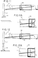
- Figs. 9-14 show how measurements might be taken by the system of the preferred embodiment as the outrigger beam and jack are used in various positions, from a fully retracted position of the outrigger beam ( Figs. 9-10 ), to a partially extended position of the beam ( Figs. 11-12 ), and in a fully extended position of the outrigger beam ( Figs. 13-14 ).
- the measurement by the magnetic sensor goes from a reading of 9 ( Fig. 9 ) with the jack in the raised position, to a reading of 8, with the jack in the lowered position ( Fig. 10 ).
- the measurement by the magnetic sensor goes from a reading of 6 with the jack in the raised position ( Fig. 11A ), to a reading of 5, with the jack in the lowered position ( Fig. 12A ).
- the measurement by the magnetic sensor goes from a reading of 3, with the jack in the raised position ( Fig. 13 ), to a reading of 2, with the jack in the lowered position ( Fig. 14 ).
- the magnetic sensors generate signals indicative of the point at which the magnetic strip crosses the sensor and can provide such signals to a system for monitoring and/or controlling operation of the crane.
- Visually perceptible indicia of the crossing point of the magnetic strip with the sensor can optionally be provided, if desired.
- the scale of any such indicia is discretionary and is not limited to that described above.
- a series of discontinuous magnetic points are used instead of a continuous strip, as long as one of the points in the series is at the sensor location when the jack is raised or lowered, the movement of the sensed point compared to the sensor will still provide an indication that the jack has been lowered or raised.
- the magnetic sensor arrangement of the present preferred embodiment serves to determine the extent to which the telescoping outrigger beam is extended from the outrigger box, thereby enabling a monitoring/control system of the crane to identify the position of the outrigger jack with respect to the remainder of the crane apparatus.
- the system of the preferred embodiment also provides signals to detect that the jack has been lowered and to signal that the jack is supporting the crane. This facilitates automatic monitoring of the condition of the crane and appropriate control in response to signals provided by the system of the preferred embodiment.
- the invention has been described thus far as comprising a combination including one or more magnetic strips 11, 13 or other series of magnetic points, and one or more magnetic sensors 15, 17.
- the invention is not limited, however, to use of such components.
- Other types of sensor arrangements can be utilized in accordance with the invention to accomplish the desired novel results.
- a sensor containing an array of magnetic switches could be used in place of the above-described magnetic sensor on the outrigger box.
- the magnetic strip 11, 13 or other form of a series of magnetic points would be used diagonally on the outrigger beam, as described.
- An array of magnetic switches such as model MG-A2-1.5N from Magnasphere would be appropriate in place of above-described sensors 15, 17.
- An alternative combination includes a wire carrying a current and a sensor to determine the position of the wire.
- the series of sensory points would each comprise points along a wire arranged similarly on the outrigger beam.
- a source of current associated with the wire would cause a current to pass through the wire.
- the alternate embodiment would include an arrangement of current sensors to determine the position of the current-carrying wire as the beam is extended from or retracted into the outrigger box.
- An example of a device that could be used to measure the current in a wire running along the beam would be a current sensor model HMC1051Z made by Honeywell.
- the HMC1051Z is a magnetic/current sensor based on magnetoresistive technology. A vertical array of these sensors could be used to detect the magnetic field caused by a current running through a wire passing near the sensor array.
- Yet another embodiment of the invention comprises sensors capable of differentiating between ferrous and non-ferrous metals.
- the outrigger box and the outrigger beam are normally fabricated from steel, a ferrous metal.
- the alternate embodiment could comprise an elongated strip of non-ferrous metal, or series of non-ferrous metal points, positioned on the outrigger beam on a diagonal, as described above.
- Each array of sensors 15 and 17 in this embodiment would comprise an array of sensors capable of differentiating between the two types of metals.
- Inductive Proximity switches with selective detection of ferrous/non-ferrous metals are available from Pepperl+Fuchs GmbH. These proximity switches comprise two separate outputs.
- One output for signals detection of a ferrous metal and one output signals detection of a non-ferrous metal is possible to differentiate between the ferrous metal of the outrigger beam and the non-ferrous metal strip positioned along the beam, thereby determining the position of the non-ferrous strip and the corresponding position of the beam.
- the sensor array could detect the position of the beam and the outrigger with respect to the outrigger box, as described above.
- the invention could comprise, in the position of each sensor 15, 17, an array of reflective photo sensors.
- Each photo sensor comprises an emitter and a receiver in one package.
- An example of such a device would be the Panasonic CNB1009 (ON2173). These devices would be arranged in a substantially vertical array, as previously described, on the outrigger box. A series of reflective sensory points, or a strip of reflective material, would be adhered to the outrigger beam in place of and in the manner of the magnetic strip.
- the various sensors of the array would have a lower or higher reading depending on the location of the reflective strip with respect to each sensor as the beam is extended from and retracted into the outrigger box, with a higher reading indicating the presence of the reflective strip adjacent one of the sensors.
- the series of sensory points could comprise a material that absorbs the transmitted radiation. In that case, a sensor in the array would indicate the proximity of the absorptive points with an indication of a lower reading.
- a second option for utilizing optical technology in the invention would be to position a series of light points on the outrigger beam in the position of magnetic strip 11, 13.
- the light points could be of various technologies including LED and fiber optic devices, adhered or otherwise attached to the beam, possibly in strip form.
- the sensor 15, 17 would comprise an array of photodiodes or photo transistors to sense the presence/proximity of the light source.
- An example of a photodiode would be the OSRAM SFH203FA.
- signals indicating the length of the outrigger beams and signals indicating that the outrigger jacks are in a lowered position and are supporting the crane may be provided to a controller.
- the controller may store such information and refer to lookup tables containing correction values for the measurements. That is, in order to perform detection that the inverted jack is supporting the crane for various lengths of extension of the beam, lookup tables can be stored including appropriate data for each outrigger beam (based on the structural characteristics of the beam that effect the manner in which the beam responds to forces during use of the outrigger).
- two lookup tables are provided for each outrigger beam.
- a first lookup table stores values related to outrigger beam extension or retraction.
- a second lookup table stores values related to the position of the jack.
- a beam extension or retraction function (Beam Ext) is performed until the beam is moved to a desired position (data is provided for full, 50%, or 0% extension, but other and additional values can be provided as desired).
- the actual beam extension length, as detected by the sensor, is set and stored.
- the jack extend function (Jack Ext) is being performed, the control system continuously monitors the output of the sensor. When the control system detects an expected change in the sensed output, it is determined that the jack is supporting the crane (Jack supporting - yes). Further extension or retraction of the jack does not change the output of the sensor and the status is set such that the jack is supporting the crane.
- the control system sets the status as that the outrigger and jack are no longer supporting the crane (Jack supporting - no). Functioning Actual beam position Jack supporting Sensor Table Beam Ext full no 3 1 Jack Ext full no 3 2 Jack Ext full yes 2 2 Beam Ext 50% no 6 1 Jack Ext 50% no 6 2 Jack Ext 50% yes 5 2 Beam Ext 0% no 9 1 Jack Ext 0% no 9 2 Jack Ext 0% yes 8 2
- the operator can operate the jack to change its position.
- the position of the jack is not determined by the controller until the sensor detects a change in position.
- the output of the sensor will automatically change to a value that relates to an unsupported crane.
- a signal of the changed condition can be provided to the operator to indicate this condition and the need to inspect and/or repair the jack.
- the controller receives signals of the change in status of the lifted jacks (no longer supporting the crane) and can use that information to signal the operator of the condition or to limit the movement of the crane.
- the controller may monitor the respective jacks and continually determine the location of the load with respect to the crane - that is, on which side the load is at any point in time. Based on this information about the location of the load, the controller may continually evaluate the suitability of the extended positions of the respective outrigger jacks or the magnitude of the load for the ongoing lifting operation. In these various ways the controller continuously monitors the output signal of the sensor to determine whether the crane has shifted during operation.
- the above disclosed embodiments reference positions of the outrigger beam of retracted (0%), fully extended (100%), and partially extended (50%).
- the present invention is not limited to these three extension lengths.
- the measuring system of the present preferred embodiment is capable of monitoring all lengths of beam extension.
- the changes in magnetic readings or other sensor readings in the system of the preferred embodiment will provide an indication that the outrigger jacks are contacting the ground and supporting the crane.
- the change in reading as discussed above may not confirm conclusively, however, whether the jacks support the crane in such manner that the wheels/tires are entirely elevated off of the ground or if the wheels may still be contacting the ground even though the jacks are supporting the crane.
- other means may be used to detect, when the outriggers are down, whether the wheels/ tires are still supporting any part of the weight of the crane or otherwise still in contact with the ground.
- a detection method such as an ABS sensor, may be used to determine if the wheels/tires turn when a small amount of torque is applied. If the wheels/ tires turn, then the tires are off of the ground. Also, the controller determines that the brakes are not applied when the wheel turn check begins.
- multiple detection devices may be used to sense the distance from a known point on the frame or chassis of the crane to the ground. If the sensed distance is greater than that of what it would be if the wheels/tires were on the ground, then the wheels/tires are off of the ground.
- a length measurement device may be used in the suspension struts or airbags associated with the wheel suspension to determine if the wheels/tires are suspended in the air.
- the process of determining whether the jacks are supporting the crane will be used without the beam extension detection aspect of the invention.
- the crane will still have at least one outrigger with a jack mounted thereon.
- the outrigger comprises a beam that is moveable along an axis of movement with respect to an outrigger support.
- the beam has the ability to move up and down a small degree with respect to the support as the weight of the crane is transferred to or from the jack.
- the system will determine whether the jack is extended and engaging the ground so as to support the crane when the outrigger is in a desired operational position.
- the term "desired operation position” means the outrigger position for which a crane operator wants to know whether the jack is supporting the crane. There may be more than one such position, such as a full beam retraction position, a full beam extension position, and half-way extended position.
- the system includes at least one sensory point attached to either the beam or the support; and a sensor attached to the other of the beam or the support in a position such that it will be able to sense the position of the at least one sensory point when the outrigger beam is in the desired operational position.
- the sensor detects the position of the sensory point as the beam moves up or down with respect to the support. A signal indicating whether the jack is providing support for the crane is thus generated.
- the sensors and magnetic strips of the preferred embodiment of the invention described above with respect to Figures 6-14 can be used to provide the at least one sensory point and the sensor.
- the present invention it is possible to automate the safety aspects of a crane control system when setting up a crane at a job site. Instead of an operator manually inputting data on the extent to which the outriggers are extended, the signals from the sensors can provide that input directly. Also, the invention makes it possible to easily have inputs for all intermediate positions of extension, between fully extended and fully retracted.
Landscapes
- Engineering & Computer Science (AREA)
- Physics & Mathematics (AREA)
- General Physics & Mathematics (AREA)
- Mechanical Engineering (AREA)
- Automation & Control Theory (AREA)
- Jib Cranes (AREA)
Applications Claiming Priority (2)
| Application Number | Priority Date | Filing Date | Title |
|---|---|---|---|
| US13/100,758 US8881919B2 (en) | 2011-05-04 | 2011-05-04 | System for measuring length of a beam extension and detecting support |
| PCT/US2012/035477 WO2012151125A2 (en) | 2011-05-04 | 2012-04-27 | System for measuring length of a beam extension and detecting support |
Publications (3)
| Publication Number | Publication Date |
|---|---|
| EP2704977A2 EP2704977A2 (en) | 2014-03-12 |
| EP2704977A4 EP2704977A4 (en) | 2015-04-29 |
| EP2704977B1 true EP2704977B1 (en) | 2017-02-01 |
Family
ID=47089534
Family Applications (1)
| Application Number | Title | Priority Date | Filing Date |
|---|---|---|---|
| EP12779649.8A Active EP2704977B1 (en) | 2011-05-04 | 2012-04-27 | System for measuring length of a beam extension and detecting support |
Country Status (10)
| Country | Link |
|---|---|
| US (1) | US8881919B2 (https=) |
| EP (1) | EP2704977B1 (https=) |
| JP (1) | JP5913570B2 (https=) |
| CN (1) | CN103648957B (https=) |
| BR (1) | BR112013028363A2 (https=) |
| CA (1) | CA2834844A1 (https=) |
| ES (1) | ES2620309T3 (https=) |
| IN (1) | IN2013CN09017A (https=) |
| RU (1) | RU2013153732A (https=) |
| WO (1) | WO2012151125A2 (https=) |
Cited By (1)
| Publication number | Priority date | Publication date | Assignee | Title |
|---|---|---|---|---|
| EP3658483B1 (en) | 2017-07-25 | 2024-11-13 | Hyva Holding BV | A levelling system for work machines |
Families Citing this family (26)
| Publication number | Priority date | Publication date | Assignee | Title |
|---|---|---|---|---|
| DE102010056584B4 (de) * | 2010-12-30 | 2018-03-29 | Asm Automation Sensorik Messtechnik Gmbh | Mobile Arbeitsmaschine |
| RU2012140237A (ru) * | 2011-09-23 | 2014-03-27 | МАНИТОВОК КРЕЙН КАМПЕНИЗ, ЭлЭлСи | Система и способы контроля выносных опор |
| US9365398B2 (en) * | 2012-10-31 | 2016-06-14 | Manitowoc Crane Companies, Llc | Outrigger pad monitoring system |
| CN103043576B (zh) * | 2012-12-30 | 2015-04-15 | 浙江鼎力机械股份有限公司 | 剪叉式防倾支撑的高空作业平台 |
| CN103043579B (zh) * | 2012-12-30 | 2015-05-20 | 浙江鼎力机械股份有限公司 | 铝合金双桅柱防倾支撑的高空作业平台 |
| CN103043578B (zh) * | 2012-12-30 | 2015-05-20 | 浙江鼎力机械股份有限公司 | 铝合金单桅柱防倾支撑的高空作业平台 |
| CN103043574B (zh) * | 2012-12-30 | 2015-05-20 | 浙江鼎力机械股份有限公司 | 一种防倾支撑的高空作业平台机座 |
| CN103043582B (zh) * | 2012-12-30 | 2015-04-15 | 浙江鼎力机械股份有限公司 | 高空作业平台的防倾支撑装置 |
| US9550475B1 (en) * | 2015-09-09 | 2017-01-24 | Altec Industries, Inc. | Securely deploying outrigger foot |
| DE102016011189B4 (de) * | 2016-09-15 | 2024-06-27 | Liebherr-Werk Ehingen Gmbh | Vorrichtung zum Stabilisieren eines Krans |
| CN106495001A (zh) * | 2016-11-08 | 2017-03-15 | 泸州汉硕信息科技有限公司 | 基于应力应变技术的起重机支腿受力监测系统 |
| IT201700019360A1 (it) * | 2017-02-21 | 2018-08-21 | Manitou Italia Srl | Stabilizzatori perfezionati per macchine operatrici semoventi |
| CN108120412B (zh) * | 2018-01-24 | 2023-08-22 | 三一汽车制造有限公司 | 间隙检测装置和机械设备 |
| EP3543670B1 (en) * | 2018-03-02 | 2021-05-05 | Manitowoc Crane Companies, LLC | Outrigger pad assembly having a force sensor, an outrigger assembly and a lifting vehicle |
| CN108862037A (zh) * | 2018-07-31 | 2018-11-23 | 徐州重型机械有限公司 | 一种起重机用基于光波原理的支腿长度测量方法 |
| US10875753B2 (en) | 2018-09-20 | 2020-12-29 | Manitou Equipment America, Llc | Telehandler boom extension monitoring system |
| GB2582260B (en) | 2019-03-01 | 2023-03-08 | Bamford Excavators Ltd | Working machine |
| GB201903399D0 (en) | 2019-03-01 | 2019-04-24 | Bamford Excavators Ltd | A working machine and a controller |
| GB2582261B (en) | 2019-03-01 | 2023-06-21 | Bamford Excavators Ltd | Working machine |
| US12012309B2 (en) * | 2019-11-22 | 2024-06-18 | Construction Robotics, Llc | Intuitive control of lifting equipment |
| KR102298591B1 (ko) * | 2020-06-09 | 2021-09-03 | 강정구 | 아웃트리거용 리드선 단선 방지장치 |
| ZA202110395B (en) | 2020-12-30 | 2023-11-29 | Manitou Italia Srl | Telehandler with facilitated alignment adjustment |
| CN114965050A (zh) * | 2022-05-12 | 2022-08-30 | 佳诺威集团股份有限公司 | 一种高密度纤维板强度检测装置 |
| CN115028074B (zh) * | 2022-06-13 | 2025-04-18 | 武桥工业装备有限责任公司 | 高速铁路起重机无线横移控制系统及控制方法 |
| GB2619764B (en) * | 2022-06-17 | 2024-10-23 | Caterpillar Inc | Automatic levelling of work machine |
| CN120368856B (zh) * | 2025-06-25 | 2025-08-22 | 中交一公局第二工程有限公司 | 一种桥梁同步顶升用位置偏移监测装置 |
Family Cites Families (12)
| Publication number | Priority date | Publication date | Assignee | Title |
|---|---|---|---|---|
| FR2339563A1 (fr) * | 1976-01-27 | 1977-08-26 | Ppm Sa | Structure telescopique munie d'un detecteur de la position relative de deux troncons |
| JPH0732299Y2 (ja) | 1989-11-29 | 1995-07-26 | 株式会社アイチコーポレーション | アウトリガ張出位置検出器 |
| JPH03105188U (https=) * | 1990-02-15 | 1991-10-31 | ||
| DE4494429T1 (de) * | 1993-06-28 | 1995-10-19 | Komatsu Mfg Co Ltd | Niveauregulierende Vorrichtung eines Fahrzeugkörpers für ein Arbeitsfahrzeug mit Hilfsstützen |
| JPH08301578A (ja) * | 1995-05-08 | 1996-11-19 | Aichi Corp | アウトリガの自動張出装置 |
| JP2766232B2 (ja) | 1995-10-27 | 1998-06-18 | 株式会社アイチコーポレーション | ジャッキ接地検出器 |
| JPH09156478A (ja) * | 1995-12-04 | 1997-06-17 | Shin Meiwa Ind Co Ltd | アウトリガ張出位置検出装置 |
| US6712536B2 (en) * | 2001-10-09 | 2004-03-30 | Alps Electric Co., Ltd. | Printer |
| US7221151B2 (en) | 2003-01-31 | 2007-05-22 | Delphi Technologies, Inc. | Magnetic array position sensor |
| JP4068042B2 (ja) * | 2003-10-27 | 2008-03-26 | 株式会社アイチコーポレーション | 作業車の制御装置 |
| JP2007283864A (ja) | 2006-04-14 | 2007-11-01 | Furukawa Unic Corp | アウトリガ張出検出装置 |
| JP5474617B2 (ja) * | 2010-03-10 | 2014-04-16 | 株式会社モリタホールディングス | 高所作業車用アウトリガジャッキ装置 |
-
2011
- 2011-05-04 US US13/100,758 patent/US8881919B2/en active Active
-
2012
- 2012-04-27 RU RU2013153732/11A patent/RU2013153732A/ru not_active Application Discontinuation
- 2012-04-27 IN IN9017CHN2013 patent/IN2013CN09017A/en unknown
- 2012-04-27 EP EP12779649.8A patent/EP2704977B1/en active Active
- 2012-04-27 CA CA2834844A patent/CA2834844A1/en not_active Abandoned
- 2012-04-27 JP JP2014509327A patent/JP5913570B2/ja active Active
- 2012-04-27 BR BR112013028363A patent/BR112013028363A2/pt not_active IP Right Cessation
- 2012-04-27 CN CN201280033223.7A patent/CN103648957B/zh not_active Expired - Fee Related
- 2012-04-27 WO PCT/US2012/035477 patent/WO2012151125A2/en not_active Ceased
- 2012-04-27 ES ES12779649.8T patent/ES2620309T3/es active Active
Non-Patent Citations (1)
| Title |
|---|
| None * |
Cited By (1)
| Publication number | Priority date | Publication date | Assignee | Title |
|---|---|---|---|---|
| EP3658483B1 (en) | 2017-07-25 | 2024-11-13 | Hyva Holding BV | A levelling system for work machines |
Also Published As
| Publication number | Publication date |
|---|---|
| ES2620309T3 (es) | 2017-06-28 |
| US8881919B2 (en) | 2014-11-11 |
| CA2834844A1 (en) | 2012-11-08 |
| JP5913570B2 (ja) | 2016-04-27 |
| JP2014513025A (ja) | 2014-05-29 |
| IN2013CN09017A (https=) | 2015-08-07 |
| EP2704977A2 (en) | 2014-03-12 |
| BR112013028363A2 (pt) | 2017-01-24 |
| RU2013153732A (ru) | 2015-06-10 |
| CN103648957B (zh) | 2017-02-08 |
| WO2012151125A3 (en) | 2013-01-17 |
| CN103648957A (zh) | 2014-03-19 |
| WO2012151125A2 (en) | 2012-11-08 |
| US20120279938A1 (en) | 2012-11-08 |
| EP2704977A4 (en) | 2015-04-29 |
Similar Documents
| Publication | Publication Date | Title |
|---|---|---|
| EP2704977B1 (en) | System for measuring length of a beam extension and detecting support | |
| US9365398B2 (en) | Outrigger pad monitoring system | |
| AU650359B2 (en) | Load moment indicator system | |
| JP5998204B2 (ja) | オートコンクリートポンプ | |
| US9073739B2 (en) | Controller for restricting movement of a load handling apparatus | |
| US8777027B2 (en) | Mobile crane | |
| US20230227300A1 (en) | Machine stability detection and indication for mobile lifting equipment | |
| US20140032060A1 (en) | Method and device for monitoring the stability of a loading crane mounted on a vehicle | |
| US11447379B2 (en) | Machine, controller and control method | |
| US20090319134A1 (en) | Industrial truck with optical lifting height measurement | |
| CN102602832A (zh) | 一种流动式起重机械倾翻保护的方法、装置及系统 | |
| SE534723C2 (sv) | Lastbil och förfarande för reglering av det maximalt tillåtna lyftmomentet hos en hydraulisk lastbilskran | |
| JP2019199356A (ja) | ブーム又はジブの変形量検出装置 | |
| JP7189489B2 (ja) | 移動式クレーン及びクレーンシステム | |
| KR100482972B1 (ko) | 견인차량의 크레인 밸런싱 시스템 | |
| CN218097734U (zh) | 行走式塔机及其检测装置 | |
| KR20200114529A (ko) | 고소작업차량의 수평제어 방법 | |
| KR102371635B1 (ko) | 개선된 길이감지 구조를 가지는 크레인 | |
| CN222989467U (zh) | 适用于立井双层罐笼的深度定位装置 | |
| US8943874B2 (en) | Construction machine | |
| JPH09136799A (ja) | 無人リフト | |
| IT202300001827A1 (it) | Gru con un sistema di limitazione di tiro del verricello. | |
| KR20050009102A (ko) | 휠로더의 적재 중량 측정장치 및 그 측정방법 | |
| JP2000291051A (ja) | 地中掘削機の変位計測装置 |
Legal Events
| Date | Code | Title | Description |
|---|---|---|---|
| PUAI | Public reference made under article 153(3) epc to a published international application that has entered the european phase |
Free format text: ORIGINAL CODE: 0009012 |
|
| 17P | Request for examination filed |
Effective date: 20131106 |
|
| AK | Designated contracting states |
Kind code of ref document: A2 Designated state(s): AL AT BE BG CH CY CZ DE DK EE ES FI FR GB GR HR HU IE IS IT LI LT LU LV MC MK MT NL NO PL PT RO RS SE SI SK SM TR |
|
| DAX | Request for extension of the european patent (deleted) | ||
| A4 | Supplementary search report drawn up and despatched |
Effective date: 20150401 |
|
| RIC1 | Information provided on ipc code assigned before grant |
Ipc: G01B 11/14 20060101ALI20150326BHEP Ipc: B66C 13/18 20060101ALI20150326BHEP Ipc: B66C 13/16 20060101ALI20150326BHEP Ipc: B66C 23/78 20060101AFI20150326BHEP Ipc: G01B 11/02 20060101ALI20150326BHEP |
|
| 17Q | First examination report despatched |
Effective date: 20151104 |
|
| GRAP | Despatch of communication of intention to grant a patent |
Free format text: ORIGINAL CODE: EPIDOSNIGR1 |
|
| INTG | Intention to grant announced |
Effective date: 20160824 |
|
| GRAS | Grant fee paid |
Free format text: ORIGINAL CODE: EPIDOSNIGR3 |
|
| GRAA | (expected) grant |
Free format text: ORIGINAL CODE: 0009210 |
|
| AK | Designated contracting states |
Kind code of ref document: B1 Designated state(s): AL AT BE BG CH CY CZ DE DK EE ES FI FR GB GR HR HU IE IS IT LI LT LU LV MC MK MT NL NO PL PT RO RS SE SI SK SM TR |
|
| REG | Reference to a national code |
Ref country code: GB Ref legal event code: FG4D |
|
| REG | Reference to a national code |
Ref country code: CH Ref legal event code: EP Ref country code: AT Ref legal event code: REF Ref document number: 865393 Country of ref document: AT Kind code of ref document: T Effective date: 20170215 |
|
| REG | Reference to a national code |
Ref country code: IE Ref legal event code: FG4D |
|
| REG | Reference to a national code |
Ref country code: DE Ref legal event code: R096 Ref document number: 602012028335 Country of ref document: DE |
|
| REG | Reference to a national code |
Ref country code: FR Ref legal event code: PLFP Year of fee payment: 6 |
|
| REG | Reference to a national code |
Ref country code: NL Ref legal event code: MP Effective date: 20170201 |
|
| REG | Reference to a national code |
Ref country code: LT Ref legal event code: MG4D |
|
| REG | Reference to a national code |
Ref country code: ES Ref legal event code: FG2A Ref document number: 2620309 Country of ref document: ES Kind code of ref document: T3 Effective date: 20170628 |
|
| PG25 | Lapsed in a contracting state [announced via postgrant information from national office to epo] |
Ref country code: FI Free format text: LAPSE BECAUSE OF FAILURE TO SUBMIT A TRANSLATION OF THE DESCRIPTION OR TO PAY THE FEE WITHIN THE PRESCRIBED TIME-LIMIT Effective date: 20170201 Ref country code: HR Free format text: LAPSE BECAUSE OF FAILURE TO SUBMIT A TRANSLATION OF THE DESCRIPTION OR TO PAY THE FEE WITHIN THE PRESCRIBED TIME-LIMIT Effective date: 20170201 Ref country code: GR Free format text: LAPSE BECAUSE OF FAILURE TO SUBMIT A TRANSLATION OF THE DESCRIPTION OR TO PAY THE FEE WITHIN THE PRESCRIBED TIME-LIMIT Effective date: 20170502 Ref country code: LT Free format text: LAPSE BECAUSE OF FAILURE TO SUBMIT A TRANSLATION OF THE DESCRIPTION OR TO PAY THE FEE WITHIN THE PRESCRIBED TIME-LIMIT Effective date: 20170201 Ref country code: IS Free format text: LAPSE BECAUSE OF FAILURE TO SUBMIT A TRANSLATION OF THE DESCRIPTION OR TO PAY THE FEE WITHIN THE PRESCRIBED TIME-LIMIT Effective date: 20170601 Ref country code: NO Free format text: LAPSE BECAUSE OF FAILURE TO SUBMIT A TRANSLATION OF THE DESCRIPTION OR TO PAY THE FEE WITHIN THE PRESCRIBED TIME-LIMIT Effective date: 20170501 |
|
| PG25 | Lapsed in a contracting state [announced via postgrant information from national office to epo] |
Ref country code: SE Free format text: LAPSE BECAUSE OF FAILURE TO SUBMIT A TRANSLATION OF THE DESCRIPTION OR TO PAY THE FEE WITHIN THE PRESCRIBED TIME-LIMIT Effective date: 20170201 Ref country code: PL Free format text: LAPSE BECAUSE OF FAILURE TO SUBMIT A TRANSLATION OF THE DESCRIPTION OR TO PAY THE FEE WITHIN THE PRESCRIBED TIME-LIMIT Effective date: 20170201 Ref country code: BG Free format text: LAPSE BECAUSE OF FAILURE TO SUBMIT A TRANSLATION OF THE DESCRIPTION OR TO PAY THE FEE WITHIN THE PRESCRIBED TIME-LIMIT Effective date: 20170501 Ref country code: LV Free format text: LAPSE BECAUSE OF FAILURE TO SUBMIT A TRANSLATION OF THE DESCRIPTION OR TO PAY THE FEE WITHIN THE PRESCRIBED TIME-LIMIT Effective date: 20170201 Ref country code: RS Free format text: LAPSE BECAUSE OF FAILURE TO SUBMIT A TRANSLATION OF THE DESCRIPTION OR TO PAY THE FEE WITHIN THE PRESCRIBED TIME-LIMIT Effective date: 20170201 Ref country code: PT Free format text: LAPSE BECAUSE OF FAILURE TO SUBMIT A TRANSLATION OF THE DESCRIPTION OR TO PAY THE FEE WITHIN THE PRESCRIBED TIME-LIMIT Effective date: 20170601 Ref country code: NL Free format text: LAPSE BECAUSE OF FAILURE TO SUBMIT A TRANSLATION OF THE DESCRIPTION OR TO PAY THE FEE WITHIN THE PRESCRIBED TIME-LIMIT Effective date: 20170201 |
|
| PG25 | Lapsed in a contracting state [announced via postgrant information from national office to epo] |
Ref country code: SK Free format text: LAPSE BECAUSE OF FAILURE TO SUBMIT A TRANSLATION OF THE DESCRIPTION OR TO PAY THE FEE WITHIN THE PRESCRIBED TIME-LIMIT Effective date: 20170201 Ref country code: EE Free format text: LAPSE BECAUSE OF FAILURE TO SUBMIT A TRANSLATION OF THE DESCRIPTION OR TO PAY THE FEE WITHIN THE PRESCRIBED TIME-LIMIT Effective date: 20170201 Ref country code: RO Free format text: LAPSE BECAUSE OF FAILURE TO SUBMIT A TRANSLATION OF THE DESCRIPTION OR TO PAY THE FEE WITHIN THE PRESCRIBED TIME-LIMIT Effective date: 20170201 Ref country code: CZ Free format text: LAPSE BECAUSE OF FAILURE TO SUBMIT A TRANSLATION OF THE DESCRIPTION OR TO PAY THE FEE WITHIN THE PRESCRIBED TIME-LIMIT Effective date: 20170201 |
|
| REG | Reference to a national code |
Ref country code: DE Ref legal event code: R097 Ref document number: 602012028335 Country of ref document: DE |
|
| PG25 | Lapsed in a contracting state [announced via postgrant information from national office to epo] |
Ref country code: DK Free format text: LAPSE BECAUSE OF FAILURE TO SUBMIT A TRANSLATION OF THE DESCRIPTION OR TO PAY THE FEE WITHIN THE PRESCRIBED TIME-LIMIT Effective date: 20170201 Ref country code: SM Free format text: LAPSE BECAUSE OF FAILURE TO SUBMIT A TRANSLATION OF THE DESCRIPTION OR TO PAY THE FEE WITHIN THE PRESCRIBED TIME-LIMIT Effective date: 20170201 |
|
| REG | Reference to a national code |
Ref country code: CH Ref legal event code: PL |
|
| PLBE | No opposition filed within time limit |
Free format text: ORIGINAL CODE: 0009261 |
|
| STAA | Information on the status of an ep patent application or granted ep patent |
Free format text: STATUS: NO OPPOSITION FILED WITHIN TIME LIMIT |
|
| 26N | No opposition filed |
Effective date: 20171103 |
|
| REG | Reference to a national code |
Ref country code: IE Ref legal event code: MM4A |
|
| PG25 | Lapsed in a contracting state [announced via postgrant information from national office to epo] |
Ref country code: MC Free format text: LAPSE BECAUSE OF FAILURE TO SUBMIT A TRANSLATION OF THE DESCRIPTION OR TO PAY THE FEE WITHIN THE PRESCRIBED TIME-LIMIT Effective date: 20170201 |
|
| PG25 | Lapsed in a contracting state [announced via postgrant information from national office to epo] |
Ref country code: LU Free format text: LAPSE BECAUSE OF NON-PAYMENT OF DUE FEES Effective date: 20170427 Ref country code: CH Free format text: LAPSE BECAUSE OF NON-PAYMENT OF DUE FEES Effective date: 20170430 Ref country code: LI Free format text: LAPSE BECAUSE OF NON-PAYMENT OF DUE FEES Effective date: 20170430 Ref country code: SI Free format text: LAPSE BECAUSE OF FAILURE TO SUBMIT A TRANSLATION OF THE DESCRIPTION OR TO PAY THE FEE WITHIN THE PRESCRIBED TIME-LIMIT Effective date: 20170201 |
|
| REG | Reference to a national code |
Ref country code: BE Ref legal event code: MM Effective date: 20170430 |
|
| REG | Reference to a national code |
Ref country code: FR Ref legal event code: PLFP Year of fee payment: 7 |
|
| PG25 | Lapsed in a contracting state [announced via postgrant information from national office to epo] |
Ref country code: IE Free format text: LAPSE BECAUSE OF NON-PAYMENT OF DUE FEES Effective date: 20170427 |
|
| PG25 | Lapsed in a contracting state [announced via postgrant information from national office to epo] |
Ref country code: BE Free format text: LAPSE BECAUSE OF NON-PAYMENT OF DUE FEES Effective date: 20170430 |
|
| PGFP | Annual fee paid to national office [announced via postgrant information from national office to epo] |
Ref country code: ES Payment date: 20180525 Year of fee payment: 7 |
|
| PGFP | Annual fee paid to national office [announced via postgrant information from national office to epo] |
Ref country code: AT Payment date: 20180419 Year of fee payment: 7 |
|
| PG25 | Lapsed in a contracting state [announced via postgrant information from national office to epo] |
Ref country code: MT Free format text: LAPSE BECAUSE OF NON-PAYMENT OF DUE FEES Effective date: 20170427 |
|
| PGFP | Annual fee paid to national office [announced via postgrant information from national office to epo] |
Ref country code: GB Payment date: 20180418 Year of fee payment: 7 |
|
| REG | Reference to a national code |
Ref country code: AT Ref legal event code: UEP Ref document number: 865393 Country of ref document: AT Kind code of ref document: T Effective date: 20170201 |
|
| PG25 | Lapsed in a contracting state [announced via postgrant information from national office to epo] |
Ref country code: HU Free format text: LAPSE BECAUSE OF FAILURE TO SUBMIT A TRANSLATION OF THE DESCRIPTION OR TO PAY THE FEE WITHIN THE PRESCRIBED TIME-LIMIT; INVALID AB INITIO Effective date: 20120427 |
|
| PG25 | Lapsed in a contracting state [announced via postgrant information from national office to epo] |
Ref country code: CY Free format text: LAPSE BECAUSE OF NON-PAYMENT OF DUE FEES Effective date: 20170201 |
|
| PG25 | Lapsed in a contracting state [announced via postgrant information from national office to epo] |
Ref country code: MK Free format text: LAPSE BECAUSE OF FAILURE TO SUBMIT A TRANSLATION OF THE DESCRIPTION OR TO PAY THE FEE WITHIN THE PRESCRIBED TIME-LIMIT Effective date: 20170201 |
|
| REG | Reference to a national code |
Ref country code: AT Ref legal event code: MM01 Ref document number: 865393 Country of ref document: AT Kind code of ref document: T Effective date: 20190427 |
|
| GBPC | Gb: european patent ceased through non-payment of renewal fee |
Effective date: 20190427 |
|
| PG25 | Lapsed in a contracting state [announced via postgrant information from national office to epo] |
Ref country code: AT Free format text: LAPSE BECAUSE OF NON-PAYMENT OF DUE FEES Effective date: 20190427 Ref country code: GB Free format text: LAPSE BECAUSE OF NON-PAYMENT OF DUE FEES Effective date: 20190427 |
|
| PG25 | Lapsed in a contracting state [announced via postgrant information from national office to epo] |
Ref country code: TR Free format text: LAPSE BECAUSE OF FAILURE TO SUBMIT A TRANSLATION OF THE DESCRIPTION OR TO PAY THE FEE WITHIN THE PRESCRIBED TIME-LIMIT Effective date: 20170201 |
|
| PG25 | Lapsed in a contracting state [announced via postgrant information from national office to epo] |
Ref country code: AL Free format text: LAPSE BECAUSE OF FAILURE TO SUBMIT A TRANSLATION OF THE DESCRIPTION OR TO PAY THE FEE WITHIN THE PRESCRIBED TIME-LIMIT Effective date: 20170201 |
|
| REG | Reference to a national code |
Ref country code: ES Ref legal event code: FD2A Effective date: 20200901 |
|
| PG25 | Lapsed in a contracting state [announced via postgrant information from national office to epo] |
Ref country code: ES Free format text: LAPSE BECAUSE OF NON-PAYMENT OF DUE FEES Effective date: 20190428 |
|
| P01 | Opt-out of the competence of the unified patent court (upc) registered |
Effective date: 20230515 |
|
| PGFP | Annual fee paid to national office [announced via postgrant information from national office to epo] |
Ref country code: DE Payment date: 20250422 Year of fee payment: 14 |
|
| PGFP | Annual fee paid to national office [announced via postgrant information from national office to epo] |
Ref country code: IT Payment date: 20250424 Year of fee payment: 14 |
|
| PGFP | Annual fee paid to national office [announced via postgrant information from national office to epo] |
Ref country code: FR Payment date: 20250425 Year of fee payment: 14 |