EP2704165A1 - Surface-mount inductor and production method thereof - Google Patents
Surface-mount inductor and production method thereof Download PDFInfo
- Publication number
- EP2704165A1 EP2704165A1 EP13004240.1A EP13004240A EP2704165A1 EP 2704165 A1 EP2704165 A1 EP 2704165A1 EP 13004240 A EP13004240 A EP 13004240A EP 2704165 A1 EP2704165 A1 EP 2704165A1
- Authority
- EP
- European Patent Office
- Prior art keywords
- coil
- core
- led
- mount inductor
- mold
- Prior art date
- Legal status (The legal status is an assumption and is not a legal conclusion. Google has not performed a legal analysis and makes no representation as to the accuracy of the status listed.)
- Granted
Links
- 238000004519 manufacturing process Methods 0.000 title description 3
- 239000006247 magnetic powder Substances 0.000 claims abstract description 36
- 238000004804 winding Methods 0.000 claims abstract description 34
- 238000000034 method Methods 0.000 claims description 13
- 239000002184 metal Substances 0.000 description 12
- 229910052751 metal Inorganic materials 0.000 description 12
- 239000002131 composite material Substances 0.000 description 10
- 229920005989 resin Polymers 0.000 description 10
- 239000011347 resin Substances 0.000 description 10
- XEEYBQQBJWHFJM-UHFFFAOYSA-N Iron Chemical compound [Fe] XEEYBQQBJWHFJM-UHFFFAOYSA-N 0.000 description 8
- 239000003822 epoxy resin Substances 0.000 description 6
- 239000000463 material Substances 0.000 description 6
- 229920000647 polyepoxide Polymers 0.000 description 6
- 229910052742 iron Inorganic materials 0.000 description 4
- 238000000465 moulding Methods 0.000 description 4
- 239000011230 binding agent Substances 0.000 description 3
- 238000000748 compression moulding Methods 0.000 description 2
- 229910052802 copper Inorganic materials 0.000 description 2
- 239000011521 glass Substances 0.000 description 2
- 229910052737 gold Inorganic materials 0.000 description 2
- 239000012212 insulator Substances 0.000 description 2
- 229910052759 nickel Inorganic materials 0.000 description 2
- 229910052763 palladium Inorganic materials 0.000 description 2
- 229910052718 tin Inorganic materials 0.000 description 2
- 230000000694 effects Effects 0.000 description 1
- 239000000203 mixture Substances 0.000 description 1
- 239000005011 phenolic resin Substances 0.000 description 1
- 229920006122 polyamide resin Polymers 0.000 description 1
- 229920013716 polyethylene resin Polymers 0.000 description 1
- 229920001721 polyimide Polymers 0.000 description 1
- 239000009719 polyimide resin Substances 0.000 description 1
- 229920005992 thermoplastic resin Polymers 0.000 description 1
- 229920001187 thermosetting polymer Polymers 0.000 description 1
Images


Classifications
-
- H—ELECTRICITY
- H01—ELECTRIC ELEMENTS
- H01F—MAGNETS; INDUCTANCES; TRANSFORMERS; SELECTION OF MATERIALS FOR THEIR MAGNETIC PROPERTIES
- H01F41/00—Apparatus or processes specially adapted for manufacturing or assembling magnets, inductances or transformers; Apparatus or processes specially adapted for manufacturing materials characterised by their magnetic properties
- H01F41/02—Apparatus or processes specially adapted for manufacturing or assembling magnets, inductances or transformers; Apparatus or processes specially adapted for manufacturing materials characterised by their magnetic properties for manufacturing cores, coils, or magnets
- H01F41/04—Apparatus or processes specially adapted for manufacturing or assembling magnets, inductances or transformers; Apparatus or processes specially adapted for manufacturing materials characterised by their magnetic properties for manufacturing cores, coils, or magnets for manufacturing coils
- H01F41/06—Coil winding
- H01F41/064—Winding non-flat conductive wires, e.g. rods, cables or cords
-
- H—ELECTRICITY
- H01—ELECTRIC ELEMENTS
- H01F—MAGNETS; INDUCTANCES; TRANSFORMERS; SELECTION OF MATERIALS FOR THEIR MAGNETIC PROPERTIES
- H01F27/00—Details of transformers or inductances, in general
- H01F27/28—Coils; Windings; Conductive connections
- H01F27/2847—Sheets; Strips
-
- H—ELECTRICITY
- H01—ELECTRIC ELEMENTS
- H01F—MAGNETS; INDUCTANCES; TRANSFORMERS; SELECTION OF MATERIALS FOR THEIR MAGNETIC PROPERTIES
- H01F27/00—Details of transformers or inductances, in general
- H01F27/28—Coils; Windings; Conductive connections
- H01F27/29—Terminals; Tapping arrangements for signal inductances
- H01F27/292—Surface mounted devices
-
- H—ELECTRICITY
- H01—ELECTRIC ELEMENTS
- H01F—MAGNETS; INDUCTANCES; TRANSFORMERS; SELECTION OF MATERIALS FOR THEIR MAGNETIC PROPERTIES
- H01F27/00—Details of transformers or inductances, in general
- H01F27/28—Coils; Windings; Conductive connections
- H01F27/32—Insulating of coils, windings, or parts thereof
-
- H—ELECTRICITY
- H01—ELECTRIC ELEMENTS
- H01F—MAGNETS; INDUCTANCES; TRANSFORMERS; SELECTION OF MATERIALS FOR THEIR MAGNETIC PROPERTIES
- H01F17/00—Fixed inductances of the signal type
- H01F17/04—Fixed inductances of the signal type with magnetic core
- H01F2017/048—Fixed inductances of the signal type with magnetic core with encapsulating core, e.g. made of resin and magnetic powder
-
- Y—GENERAL TAGGING OF NEW TECHNOLOGICAL DEVELOPMENTS; GENERAL TAGGING OF CROSS-SECTIONAL TECHNOLOGIES SPANNING OVER SEVERAL SECTIONS OF THE IPC; TECHNICAL SUBJECTS COVERED BY FORMER USPC CROSS-REFERENCE ART COLLECTIONS [XRACs] AND DIGESTS
- Y10—TECHNICAL SUBJECTS COVERED BY FORMER USPC
- Y10T—TECHNICAL SUBJECTS COVERED BY FORMER US CLASSIFICATION
- Y10T29/00—Metal working
- Y10T29/49—Method of mechanical manufacture
- Y10T29/49002—Electrical device making
- Y10T29/4902—Electromagnet, transformer or inductor
- Y10T29/49071—Electromagnet, transformer or inductor by winding or coiling
Definitions
- the present invention relates to a surface-mount inductor comprising: a coil formed by winding a winding wire; and a core containing a magnetic powder and including the coil therein, and to a method of producing the inductor.
- a conventional surface-mount inductor includes a type which is obtained by: winding a winding wire to form a coil; and forming a core while allowing the coil to be included therein, through pressure molding using a magnetic powder and binder, or compressing molding using a composite material of a magnetic powder and a resin. External terminals are formed on the surface of the core, and the coil is connected therebetween.
- This conventional surface-mount inductor is formed, as illustrated in FIG.
- a coil 61 formed by winding a winding wire, on an E-shaped tablet 62A formed from a composite material of a magnetic powder and a resin; housing the coil 61 and the E-shaped tablet 62A in a mold comprising an lower mold 60A and an upper mold 60B such that each of led-out ends 61A, 61B of the coil 61 is sandwiched between the E-shaped tablet 62A and respective ones of inner walls of the mold; disposing a tablet 62B formed from a composite material of a magnetic powder and a resin on the tablet 62A; and thermally compressing them with the mold and a punch 60C (see, for example, the Patent Document 1).
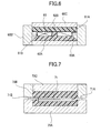
- This conventional surface-mount inductor may also be formed, as illustrated in FIG. 7 , by: housing a coil 71, formed by winding a winding wire, in a mold comprising an lower mold 70A and an upper mold 70B; holding led-out ends 71A, 71B of the coil 61 with the lower mold 70A and the upper mold 70B; and filling a magnetic powder and binder in the mold and subjecting them to a pressure molding performed with the mold and a punch 70C at a high pressure, or disposing a composite material of a magnetic powder and a resin on upper and lower regions of the coil 71 in the mold and thermally compressing them with the mold and the punch 70C (see, for example, the Patent Document 2).
- the E-shaped tablet may allow the coil to be disposed in a predetermined position in a mold, and prevent the coil from being displaced from a predetermined position in the core, or prevent the led-out ends from being buried in the core.
- the mold may allow the coil to be disposed in a predetermined position in a mold, and prevent the coil from being displaced from a predetermined position in the core, or prevent the led-out ends from being buried in the core.
- a conventional surface-mount inductor has a problem with generation of a large burr in the core due to a leakage of materials constituting the core from a portion of the mold which holds the led-out ends of the coil. In the event of generation of the large burr in the core, it is difficult to remove the burr because of the small size of the surface-mount inductor.
- the present invention provides a surface-mount inductor comprising: a coil formed by winding a winding wire; and a core containing a magnetic powder and including the coil therein, wherein each of opposite led-out ends of the coil is exposed on respective ones of opposed side surfaces of the core, and each of the led-out ends of the coil is connected to an external electrode formed on the core.
- the present invention also provides a method of producing a surface-mount inductor which comprises: a coil formed by winding a winding wire; and a core containing a magnetic powder and including the coil therein, wherein the coil is processed to allow each of opposite led-out ends thereof to come into contact with respective ones of opposed inner walls of a mold.
- a surface-mount inductor comprising: a coil formed by winding a winding wire; and a core containing a magnetic powder and including the coil therein, wherein each of opposite led-out ends of the coil is exposed on respective ones of opposed side surfaces of the core, and each of the led-out ends of the coil is connected to an external electrode formed on the core.
- a method of producing a surface-mount inductor which comprises: a coil formed by winding a winding wire; and a core containing a magnetic powder and including the coil therein, wherein the coil is processed to allow each of opposite led-out ends thereof to come into contact with respective ones of opposed inner walls of a mold.
- a surface-mount inductor of the present invention comprises a coil formed by winding a winding wire, and a core containing a magnetic powder and including the coil therein.
- the coil has opposite led-out ends, each of which is exposed on respective ones of opposed side surfaces of the core, and each of the led-out ends of the coil is connected to an external electrode formed on the core.
- the coil position in the core can be determined by the led-out ends, so that it is not necessary to use a complicated shape of tablet or to use a particular kind of mold.
- this surface-mount inductor does not use any complicated shape of tablet, and thus the coil size can be freely set within the range of core size. This makes it possible to provide contribution in improvement of inductance value, DC resistance value, efficiency, characteristics such as DC superimposition characteristics, and in downsizing of the surface-mount inductor.
- a method of producing a surface-mount inductor of the present invention comprises forming a coil by winding a winding wire, and housing the coil and a material containing a magnetic powder in a mold to form a core including the coil therein.
- the coil has opposite led-out ends, each of which is processed to come into contact with respective ones of opposed inner walls of the mold.
- the coil position in the mold can be determined by the led-out ends, so that the coil can be positioned in a predetermined position in the core, and the led-out ends can be exposed on predetermined positions in the core surface to ensure each of them to be connected to an external electrode without using a complicated shape of tablet or using a particular kind of mold.
- this method of producing a surface-mount inductor does not use any complicated shape of tablet, and thus the coil size can be freely set within the range of core size. This makes it possible to provide contribution in improvement of inductance value, DC resistance value, efficiency, characteristics such as DC superimposition characteristics, and in downsizing of the surface-mount inductor.
- FIG. 1 is a transparent perspective view illustrating a first embodiment of a surface-mount inductor according to the present invention.
- the reference numeral 11 designates a coil
- 12 designates a core.
- the coil 11 is formed by winding a rectangular wire in two tiers to allow its opposite ends to be positioned on an outer periphery of the coil.
- the coil 11 is disposed in the core 12 described below, and is processed to allow each opposite end of the rectangular wire which is led out from the outer periphery of the coil to be exposed along an end surface and respective ones of two opposed side surfaces adjacent to the end surface of the core 12 to form led-out ends 11A and 11B.
- the core 12 includes the coil 11 using a composite material of a magnetic powder and a resin, and is formed to allow each of the opposite led-out ends 11A and 11B of the coil 11 to be exposed on the end surface and respective ones of two side surfaces which are adjacent to the end surface and opposed to each other.
- the magnetic powder a metal magnetic powder is used.
- the resin an epoxy resin is used.
- External electrodes 13A and 13B are formed on the surface of the core 12, as illustrated in FIG.
- the coil 11 is connected between the external electrodes 13A and 13B by the led-out ends 11A of the coil 11 being connected to the external electrodes 13A and the led-out ends 11B of the coil 11 being connected to the external electrodes 13B.
- This surface-mount inductor is produced in the following manner. Firstly, a coil is formed by winding a rectangular wire in two tiers to allow its opposite ends to be positioned on an outer periphery of the coil. Then, terminal ends of the rectangular wire positioned on an outer periphery of the coil are processed to allow each of them to be exposed along an end surface and respective ones of two opposed side surfaces adjacent to the end surface of the core to form led-out ends. Next, as illustrated in FIG. 3 , the coil 31 is housed in a mold 30 to allow each of the surfaces of its led-out ends 31A, 31B to be along and in contact with respective ones of opposed inner walls and an inner wall adjoining to both of the opposed inner walls of the mold 30.
- a tablet made by pre-forming a composite material of an iron-based metal magnetic powder and an epoxy resin into a plate is preliminarily housed in an inner bottom surface of the mold 30, in which the coil 31 is housed. Further, the composite material of an iron-based metal magnetic powder and an epoxy resin is filled in the mold 30 in which the coil 31 is housed, or the tablet made by pre-forming the composite material of an iron-based metal magnetic powder and an epoxy resin into a plate is housed in the mold 30 in which the coil 31 is housed.
- a compression molding performed by the mold 30 and a punch at a temperature from 120 to 250 °C, thereby to form a core 12 including the coil, where the core 12 is formed to allow each of the opposite led-out ends of the coil to be exposed on the end surface and respective ones of two side surfaces which are adjacent to the end surface and opposed to each other.
- an electrically-conductive paste is applied on the core 12 and cured to form external electrodes 13A, 13B on the core 12.
- the external electrodes 13A, 13B may be plated with a material formed by appropriately selecting one or more from materials such as Ni, Sn, Cu, Au and Pd.
- FIG. 4 is a transparent perspective view illustrating a second embodiment of a surface-mount inductor according to the present invention.
- the coil 14 is formed by winding a rectangular wire in two tiers to allow its opposite ends to be positioned on an outer periphery of the coil.
- the coil 41 is disposed in the core 42, and is processed in a wave shape to allow each end of the rectangular wire which is led out from the outer periphery of the coil to be exposed on respective ones of opposed side surfaces of the core 42 to form led-out ends 41A and 41B.
- the core 42 includes the coil 41 using a composite material of a magnetic powder and a resin, and is formed to allow each of the opposite wave-shaped led-out ends 41A and 41B of the coil 41 to be exposed on respective ones of two opposed side surfaces.
- a metal magnetic powder is used for the magnetic powder.
- a resin an epoxy resin is used for the resin.
- External electrodes 13A and 13B are formed on the surface of the core, as illustrated in FIG. 2 . Then, the coil 41 is connected between the external electrodes 13A and 13B by the led-out ends 41A of the coil 41 being connected to the external electrodes 13A and the led-out ends 41B of the coil 41 being connected to the external electrodes 13B.
- This surface-mount inductor is produced in the following manner. Firstly, a coil is formed by winding a rectangular wire in two tiers to allow its opposite ends to be positioned on an outer periphery of the coil. Then, terminal ends of the rectangular wire positioned on an outer periphery of the coil are processed to allow each of them to be exposed on respective ones of opposed side surfaces of the core to form wave-shaped led-out ends. Next, as illustrated in FIG. 5 , the coil 51 is housed in a mold 50 to allow each of its opposite led-out ends 51A, 51B to come into contact with respective ones of opposed inner walls of the mold 50.
- the led-out ends 51A, 51B of the coil 51 are provided with spring characteristics because they are formed in a wave shape, so that the led-out ends 51A, 51B make contacts between the opposed inner walls of the mold 50 more strongly than those illustrated in FIG. 3 .
- a composite material of an iron-based metal magnetic powder and an epoxy resin is filled in the mold 50 in which the coil 51 is housed. Subsequently, these are subjected to a compression molding performed by the mold 50 and a punch at a temperature from 120 to 250 °C, thereby to form a core 42 including the coil, where the core 42 is formed to allow each of the opposite led-out ends of the coil to be exposed on respective ones of two side surfaces opposed to each other. Then, an electrically-conductive paste is applied on the core 42 and cured to form external electrodes on the core 42.
- the external electrodes may be plated with a material formed by appropriately selecting one or more from materials such as Ni, Sn, Cu, Au and Pd.
- the metal magnetic powder for use in the core may have a wide variety of compositions, and may be a metal magnetic powder having a surface coated with an insulator such as a glass, or a metal magnetic powder having an oxidized surface.
- the resin for use in the core may be other thermosetting resin such as a polyimide resin or a phenol resin, or may be a thermoplastic resin such as a polyethylene resin or a polyamide resin.
- the core may be formed by filling a magnetic powder and binder in a mold in which a coil is housed, and subjecting them to pressure molding performed with the mold and a punch at a high pressure.
- the magnetic powder for use in the core may be a metal magnetic powder, a metal magnetic powder having a surface coated with insulators such as a glass, or a metal magnetic powder having an oxidized surface.
Abstract
Description
- The present invention relates to a surface-mount inductor comprising: a coil formed by winding a winding wire; and a core containing a magnetic powder and including the coil therein, and to a method of producing the inductor.
- A conventional surface-mount inductor includes a type which is obtained by: winding a winding wire to form a coil; and forming a core while allowing the coil to be included therein, through pressure molding using a magnetic powder and binder, or compressing molding using a composite material of a magnetic powder and a resin. External terminals are formed on the surface of the core, and the coil is connected therebetween.
This conventional surface-mount inductor is formed, as illustrated inFIG. 6 , by: disposing acoil 61, formed by winding a winding wire, on anE-shaped tablet 62A formed from a composite material of a magnetic powder and a resin; housing thecoil 61 and theE-shaped tablet 62A in a mold comprising anlower mold 60A and anupper mold 60B such that each of led-outends coil 61 is sandwiched between theE-shaped tablet 62A and respective ones of inner walls of the mold; disposing atablet 62B formed from a composite material of a magnetic powder and a resin on thetablet 62A; and thermally compressing them with the mold and apunch 60C (see, for example, the Patent Document 1).
This conventional surface-mount inductor may also be formed, as illustrated inFIG. 7 , by: housing acoil 71, formed by winding a winding wire, in a mold comprising anlower mold 70A and anupper mold 70B; holding led-outends coil 61 with thelower mold 70A and theupper mold 70B; and filling a magnetic powder and binder in the mold and subjecting them to a pressure molding performed with the mold and apunch 70C at a high pressure, or disposing a composite material of a magnetic powder and a resin on upper and lower regions of thecoil 71 in the mold and thermally compressing them with the mold and thepunch 70C (see, for example, the Patent Document 2). -
- Patent Document 1:
JP 2010-245473A - Patent Document 2:
JP 2009-170488A - In the conventional surface-mount inductor formed by using an E-shaped tablet, the E-shaped tablet may allow the coil to be disposed in a predetermined position in a mold, and prevent the coil from being displaced from a predetermined position in the core, or prevent the led-out ends from being buried in the core. However, when it is required to downsize the E-shaped tablet along with downsizing of the surface-mount inductor, it is difficult for such a conventional surface-mount inductor to form the E-shaped tablet due to its complicated shape. Even when the E-shaped tablet can be formed, there is a problem with the tablet that it is likely to be broken when the coil is mounted thereon or it is housed in the mold because it is impossible to keep the strength needed for mounting the coil thereon or for handling the tablet when housed in the mold. To keep the strength of the E-shaped tablet, it is necessary to make the thickness between outer surfaces of the tablet and the coil greater. However, this results in larger size of the surface-mount inductor, or limited size of the coil, and thus sufficient characteristics are often unobtainable.
On the other hand, in the conventional surface-mount inductor formed by holding the led-out ends of the coil by the mold, the mold may allow the coil to be disposed in a predetermined position in a mold, and prevent the coil from being displaced from a predetermined position in the core, or prevent the led-out ends from being buried in the core. However, such a conventional surface-mount inductor has a problem with generation of a large burr in the core due to a leakage of materials constituting the core from a portion of the mold which holds the led-out ends of the coil. In the event of generation of the large burr in the core, it is difficult to remove the burr because of the small size of the surface-mount inductor. - It is therefore an object of the present invention to provide a surface-mount inductor and a method of producing the inductor, where the surface-mount inductor is capable of positioning a coil in a predetermined position in a mold, thereby to position the coil in a predetermined position of a core and to prevent led-out ends from being buried in the core without using any special components or expensive units.
- The present invention provides a surface-mount inductor comprising: a coil formed by winding a winding wire; and a core containing a magnetic powder and including the coil therein, wherein each of opposite led-out ends of the coil is exposed on respective ones of opposed side surfaces of the core, and each of the led-out ends of the coil is connected to an external electrode formed on the core.
The present invention also provides a method of producing a surface-mount inductor which comprises: a coil formed by winding a winding wire; and a core containing a magnetic powder and including the coil therein, wherein the coil is processed to allow each of opposite led-out ends thereof to come into contact with respective ones of opposed inner walls of a mold. - According to the present invention, there is provided a surface-mount inductor comprising: a coil formed by winding a winding wire; and a core containing a magnetic powder and including the coil therein, wherein each of opposite led-out ends of the coil is exposed on respective ones of opposed side surfaces of the core, and each of the led-out ends of the coil is connected to an external electrode formed on the core. This makes it possible to position the coil in a predetermined position of the core to ensure the coil to be connected to external electrodes without using any special components or expensive units.
According to the present invention, there is also provided a method of producing a surface-mount inductor which comprises: a coil formed by winding a winding wire; and a core containing a magnetic powder and including the coil therein, wherein the coil is processed to allow each of opposite led-out ends thereof to come into contact with respective ones of opposed inner walls of a mold. This makes it possible to position the coil in a predetermined position in the mold, thereby to position the coil in a predetermined position of the core and to expose the led-out ends on predetermined positions in a core surface without using any special components or expensive units. -
-
FIG. 1 is a transparent perspective view illustrating a first embodiment of a surface-mount inductor according to the present invention. -
FIG. 2 is a perspective view of the surface-mount inductor according to the present invention. -
FIG. 3 is a partial cross-sectional view illustrating a first embodiment of a method of producing the surface-mount inductor according to the present invention. -
FIG. 4 is a transparent perspective view illustrating a second embodiment of the surface-mount inductor according to the present invention. -
FIG. 5 is a partial cross-sectional view illustrating a second embodiment of the method of producing the surface-mount inductor according to the present invention. -
FIG. 6 is a partial cross-sectional view illustrating a method of producing a conventional surface-mount inductor. -
FIG. 7 is a partial cross-sectional view illustrating another method of producing a conventional surface-mount inductor. - A surface-mount inductor of the present invention comprises a coil formed by winding a winding wire, and a core containing a magnetic powder and including the coil therein. The coil has opposite led-out ends, each of which is exposed on respective ones of opposed side surfaces of the core, and each of the led-out ends of the coil is connected to an external electrode formed on the core.
Thus, in this surface-mount inductor, the coil position in the core can be determined by the led-out ends, so that it is not necessary to use a complicated shape of tablet or to use a particular kind of mold. Further, this surface-mount inductor does not use any complicated shape of tablet, and thus the coil size can be freely set within the range of core size. This makes it possible to provide contribution in improvement of inductance value, DC resistance value, efficiency, characteristics such as DC superimposition characteristics, and in downsizing of the surface-mount inductor. - A method of producing a surface-mount inductor of the present invention comprises forming a coil by winding a winding wire, and housing the coil and a material containing a magnetic powder in a mold to form a core including the coil therein. The coil has opposite led-out ends, each of which is processed to come into contact with respective ones of opposed inner walls of the mold.
Thus, in this method of producing a surface-mount inductor, the coil position in the mold can be determined by the led-out ends, so that the coil can be positioned in a predetermined position in the core, and the led-out ends can be exposed on predetermined positions in the core surface to ensure each of them to be connected to an external electrode without using a complicated shape of tablet or using a particular kind of mold. Further, this method of producing a surface-mount inductor does not use any complicated shape of tablet, and thus the coil size can be freely set within the range of core size. This makes it possible to provide contribution in improvement of inductance value, DC resistance value, efficiency, characteristics such as DC superimposition characteristics, and in downsizing of the surface-mount inductor. - Embodiments of the surface-mount inductor and the production method thereof according to the present invention will now be described with reference to
FIGS. 1 to 5 .
FIG. 1 is a transparent perspective view illustrating a first embodiment of a surface-mount inductor according to the present invention.
InFIG. 1 , thereference numeral 11 designates a coil, and 12 designates a core.
Thecoil 11 is formed by winding a rectangular wire in two tiers to allow its opposite ends to be positioned on an outer periphery of the coil. Thecoil 11 is disposed in thecore 12 described below, and is processed to allow each opposite end of the rectangular wire which is led out from the outer periphery of the coil to be exposed along an end surface and respective ones of two opposed side surfaces adjacent to the end surface of thecore 12 to form led-outends
Thecore 12 includes thecoil 11 using a composite material of a magnetic powder and a resin, and is formed to allow each of the opposite led-outends coil 11 to be exposed on the end surface and respective ones of two side surfaces which are adjacent to the end surface and opposed to each other. For the magnetic powder, a metal magnetic powder is used. For the resin, an epoxy resin is used.External electrodes core 12, as illustrated inFIG. 2 .
Then, thecoil 11 is connected between theexternal electrodes out ends 11A of thecoil 11 being connected to theexternal electrodes 13A and the led-out ends 11B of thecoil 11 being connected to theexternal electrodes 13B. - This surface-mount inductor is produced in the following manner. Firstly, a coil is formed by winding a rectangular wire in two tiers to allow its opposite ends to be positioned on an outer periphery of the coil.
Then, terminal ends of the rectangular wire positioned on an outer periphery of the coil are processed to allow each of them to be exposed along an end surface and respective ones of two opposed side surfaces adjacent to the end surface of the core to form led-out ends.
Next, as illustrated inFIG. 3 , thecoil 31 is housed in amold 30 to allow each of the surfaces of its led-out ends mold 30. At this time, a tablet made by pre-forming a composite material of an iron-based metal magnetic powder and an epoxy resin into a plate is preliminarily housed in an inner bottom surface of themold 30, in which thecoil 31 is housed.
Further, the composite material of an iron-based metal magnetic powder and an epoxy resin is filled in themold 30 in which thecoil 31 is housed, or the tablet made by pre-forming the composite material of an iron-based metal magnetic powder and an epoxy resin into a plate is housed in themold 30 in which thecoil 31 is housed.
Subsequently, these are subjected to a compression molding performed by themold 30 and a punch at a temperature from 120 to 250 °C, thereby to form acore 12 including the coil, where thecore 12 is formed to allow each of the opposite led-out ends of the coil to be exposed on the end surface and respective ones of two side surfaces which are adjacent to the end surface and opposed to each other.
Then, an electrically-conductive paste is applied on thecore 12 and cured to formexternal electrodes core 12. Theexternal electrodes -
FIG. 4 is a transparent perspective view illustrating a second embodiment of a surface-mount inductor according to the present invention.
The coil 14 is formed by winding a rectangular wire in two tiers to allow its opposite ends to be positioned on an outer periphery of the coil. Thecoil 41 is disposed in thecore 42, and is processed in a wave shape to allow each end of the rectangular wire which is led out from the outer periphery of the coil to be exposed on respective ones of opposed side surfaces of the core 42 to form led-out ends 41A and 41B.
Thecore 42 includes thecoil 41 using a composite material of a magnetic powder and a resin, and is formed to allow each of the opposite wave-shaped led-out ends 41A and 41B of thecoil 41 to be exposed on respective ones of two opposed side surfaces. For the magnetic powder, a metal magnetic powder is used. For the resin, an epoxy resin is used.External electrodes FIG. 2 .
Then, thecoil 41 is connected between theexternal electrodes coil 41 being connected to theexternal electrodes 13A and the led-out ends 41B of thecoil 41 being connected to theexternal electrodes 13B. - This surface-mount inductor is produced in the following manner. Firstly, a coil is formed by winding a rectangular wire in two tiers to allow its opposite ends to be positioned on an outer periphery of the coil.
Then, terminal ends of the rectangular wire positioned on an outer periphery of the coil are processed to allow each of them to be exposed on respective ones of opposed side surfaces of the core to form wave-shaped led-out ends.
Next, as illustrated inFIG. 5 , thecoil 51 is housed in amold 50 to allow each of its opposite led-out ends 51A, 51B to come into contact with respective ones of opposed inner walls of themold 50. The led-out ends 51A, 51B of thecoil 51 are provided with spring characteristics because they are formed in a wave shape, so that the led-out ends 51A, 51B make contacts between the opposed inner walls of themold 50 more strongly than those illustrated inFIG. 3 .
Further, a composite material of an iron-based metal magnetic powder and an epoxy resin is filled in themold 50 in which thecoil 51 is housed.
Subsequently, these are subjected to a compression molding performed by themold 50 and a punch at a temperature from 120 to 250 °C, thereby to form a core 42 including the coil, where thecore 42 is formed to allow each of the opposite led-out ends of the coil to be exposed on respective ones of two side surfaces opposed to each other.
Then, an electrically-conductive paste is applied on thecore 42 and cured to form external electrodes on thecore 42. The external electrodes may be plated with a material formed by appropriately selecting one or more from materials such as Ni, Sn, Cu, Au and Pd. - While embodiments of a surface-mount inductor and a production method thereof according to the present invention have been described above, the invention is not limited to the embodiments. For example, the metal magnetic powder for use in the core may have a wide variety of compositions, and may be a metal magnetic powder having a surface coated with an insulator such as a glass, or a metal magnetic powder having an oxidized surface. Further, the resin for use in the core may be other thermosetting resin such as a polyimide resin or a phenol resin, or may be a thermoplastic resin such as a polyethylene resin or a polyamide resin. Furthermore, the core may be formed by filling a magnetic powder and binder in a mold in which a coil is housed, and subjecting them to pressure molding performed with the mold and a punch at a high pressure. In this case, the magnetic powder for use in the core may be a metal magnetic powder, a metal magnetic powder having a surface coated with insulators such as a glass, or a metal magnetic powder having an oxidized surface.
-
- 11: coil
- 12: core
Claims (5)
- A surface-mount inductor comprising: a coil formed by winding a winding wire; and a core containing a magnetic powder and including the coil therein,
wherein each of led-out ends of the coil is exposed on respective one of side surfaces of the core, and each of the led-out ends of the coil is connected to an external electrode formed on the core. - A surface-mount inductor comprising: a coil formed by winding a winding wire; and a core containing a magnetic powder and including the coil therein,
wherein each of led-out ends of the coil is exposed on an end surface and respective one of side surfaces of the core, and each of the led-out ends of the coil is connected to an external electrode formed on the core. - The surface-mount inductor as defined in claim 1 or 2, wherein each of the led-out ends of the coil has elasticity.
- A method of producing a surface-mount inductor which comprises: a coil formed by winding a winding wire; and a core containing a magnetic powder and including the coil therein,
wherein the coil is processed to allow each of led-out ends thereof to come into contact with respective one of opposed inner walls of a mold. - A method of producing a surface-mount inductor which comprises: a coil formed by winding a winding wire; and a core containing a magnetic powder and including the coil therein,
wherein the coil is processed to allow each of led-out ends thereof to come into contact with respective one of opposed inner walls and an inner wall adjoining to the inner wall of a mold.
Applications Claiming Priority (1)
| Application Number | Priority Date | Filing Date | Title |
|---|---|---|---|
| JP2012191117A JP5755615B2 (en) | 2012-08-31 | 2012-08-31 | Surface mount inductor and manufacturing method thereof |
Publications (2)
| Publication Number | Publication Date |
|---|---|
| EP2704165A1 true EP2704165A1 (en) | 2014-03-05 |
| EP2704165B1 EP2704165B1 (en) | 2020-04-01 |
Family
ID=49084722
Family Applications (1)
| Application Number | Title | Priority Date | Filing Date |
|---|---|---|---|
| EP13004240.1A Active EP2704165B1 (en) | 2012-08-31 | 2013-08-28 | Surface-mount inductor and production method thereof |
Country Status (6)
| Country | Link |
|---|---|
| US (1) | US9305702B2 (en) |
| EP (1) | EP2704165B1 (en) |
| JP (1) | JP5755615B2 (en) |
| KR (1) | KR102046344B1 (en) |
| CN (1) | CN103680817B (en) |
| TW (1) | TWI564918B (en) |
Cited By (2)
| Publication number | Priority date | Publication date | Assignee | Title |
|---|---|---|---|---|
| US20200090850A1 (en) * | 2018-09-19 | 2020-03-19 | Murata Manufacturing Co., Ltd. | Surface mount inductor and method of manufacturing surface mount inductor |
| US20200152379A1 (en) * | 2018-11-14 | 2020-05-14 | Asustek Computer Inc. | Inductor and method for manufacturing same |
Families Citing this family (19)
| Publication number | Priority date | Publication date | Assignee | Title |
|---|---|---|---|---|
| JP5974283B2 (en) * | 2012-07-06 | 2016-08-23 | パナソニックIpマネジメント株式会社 | Inductor manufacturing method |
| JP6340805B2 (en) * | 2014-01-31 | 2018-06-13 | 株式会社村田製作所 | Electronic components |
| JP6308036B2 (en) * | 2014-06-09 | 2018-04-11 | 株式会社デンソー | Reactor |
| JP6060116B2 (en) * | 2014-07-18 | 2017-01-11 | 東光株式会社 | Surface mount inductor and manufacturing method thereof |
| KR102107036B1 (en) * | 2015-01-27 | 2020-05-07 | 삼성전기주식회사 | Wire-wound inductor and method for manufacturing thereof |
| KR20160124328A (en) * | 2015-04-16 | 2016-10-27 | 삼성전기주식회사 | Chip component and manufacturing method thereof |
| JP6477429B2 (en) * | 2015-11-09 | 2019-03-06 | 株式会社村田製作所 | Coil parts |
| JP6463256B2 (en) * | 2015-12-11 | 2019-01-30 | 太陽誘電株式会社 | Coil parts, manufacturing method thereof, electronic equipment |
| JP6459986B2 (en) * | 2016-01-08 | 2019-01-30 | 株式会社村田製作所 | Metal magnetic powder-containing sheet, inductor manufacturing method, and inductor |
| KR102653217B1 (en) * | 2016-11-15 | 2024-04-01 | 삼성전기주식회사 | Inductor |
| WO2018142666A1 (en) * | 2017-01-31 | 2018-08-09 | アルプス電気株式会社 | Powder compact core, method for manufacturing powder compact core, electric/electronic component provided with powder compact core, and electric/electronic apparatus having electric/electronic component mounted therein |
| KR102004807B1 (en) * | 2017-06-13 | 2019-10-08 | 삼성전기주식회사 | Coil component |
| JP7140481B2 (en) * | 2017-09-25 | 2022-09-21 | 日東電工株式会社 | Inductor and manufacturing method thereof |
| KR102501904B1 (en) * | 2017-12-07 | 2023-02-21 | 삼성전기주식회사 | Winding type inductor |
| JP6784269B2 (en) * | 2018-03-01 | 2020-11-11 | 株式会社村田製作所 | Surface mount inductor |
| JP6549779B2 (en) * | 2018-12-28 | 2019-07-24 | 太陽誘電株式会社 | Coil component, method of manufacturing the same, electronic device |
| US20210035730A1 (en) * | 2019-07-31 | 2021-02-04 | Murata Manufacturing Co., Ltd. | Inductor |
| CN110718359A (en) * | 2019-11-08 | 2020-01-21 | 汕头市信技电子科技有限公司 | Manufacturing structure and method of surface-mounted integrally-formed inductor |
| CN113035528A (en) * | 2019-12-24 | 2021-06-25 | 佳邦科技股份有限公司 | Carrier-free bottom electrode integrated power inductor and manufacturing method thereof |
Citations (2)
| Publication number | Priority date | Publication date | Assignee | Title |
|---|---|---|---|---|
| JP2009170488A (en) | 2008-01-11 | 2009-07-30 | Yoshizumi Fukui | Method for manufacturing mold coil |
| US20100259353A1 (en) * | 2009-04-10 | 2010-10-14 | Toko, Inc. | Surface-Mount Inductor and Method of Producing the Same |
Family Cites Families (13)
| Publication number | Priority date | Publication date | Assignee | Title |
|---|---|---|---|---|
| JP3204243B2 (en) * | 1999-03-12 | 2001-09-04 | 株式会社村田製作所 | Surface mount type coil parts |
| JP4301988B2 (en) * | 2004-03-31 | 2009-07-22 | アルプス電気株式会社 | Method for producing a coil-filled green compact |
| TWM278046U (en) * | 2005-02-22 | 2005-10-11 | Traben Co Ltd | Inductor component |
| JP4933830B2 (en) * | 2006-05-09 | 2012-05-16 | スミダコーポレーション株式会社 | Inductor |
| CN201138593Y (en) * | 2008-01-04 | 2008-10-22 | 深圳振华富电子有限公司 | Stacked magnetic bead |
| US20090250836A1 (en) * | 2008-04-04 | 2009-10-08 | Toko, Inc. | Production Method for Molded Coil |
| JP5329202B2 (en) * | 2008-12-19 | 2013-10-30 | 東光株式会社 | Molded coil manufacturing method |
| US20100134233A1 (en) * | 2008-11-28 | 2010-06-03 | Shih-Jen Wang | Inductor and method for making the same |
| JP4961441B2 (en) * | 2009-01-30 | 2012-06-27 | 東光株式会社 | Molded coil manufacturing method |
| JP2010186910A (en) * | 2009-02-13 | 2010-08-26 | Toko Inc | Method of manufacturing mold coil |
| JP5516357B2 (en) * | 2010-11-17 | 2014-06-11 | スミダコーポレーション株式会社 | Magnetic element |
| JP2012160507A (en) * | 2011-01-31 | 2012-08-23 | Toko Inc | Surface mount inductor and method for manufacturing surface mount inductor |
| JP5974283B2 (en) * | 2012-07-06 | 2016-08-23 | パナソニックIpマネジメント株式会社 | Inductor manufacturing method |
-
2012
- 2012-08-31 JP JP2012191117A patent/JP5755615B2/en active Active
-
2013
- 2013-08-28 EP EP13004240.1A patent/EP2704165B1/en active Active
- 2013-08-29 TW TW102131003A patent/TWI564918B/en active
- 2013-08-29 KR KR1020130103002A patent/KR102046344B1/en active IP Right Grant
- 2013-08-30 CN CN201310390601.3A patent/CN103680817B/en active Active
- 2013-08-30 US US14/015,477 patent/US9305702B2/en active Active
Patent Citations (3)
| Publication number | Priority date | Publication date | Assignee | Title |
|---|---|---|---|---|
| JP2009170488A (en) | 2008-01-11 | 2009-07-30 | Yoshizumi Fukui | Method for manufacturing mold coil |
| US20100259353A1 (en) * | 2009-04-10 | 2010-10-14 | Toko, Inc. | Surface-Mount Inductor and Method of Producing the Same |
| JP2010245473A (en) | 2009-04-10 | 2010-10-28 | Toko Inc | Method of manufacturing surface mounting inductor and the surface mounting inductor |
Cited By (3)
| Publication number | Priority date | Publication date | Assignee | Title |
|---|---|---|---|---|
| US20200090850A1 (en) * | 2018-09-19 | 2020-03-19 | Murata Manufacturing Co., Ltd. | Surface mount inductor and method of manufacturing surface mount inductor |
| US11817248B2 (en) * | 2018-09-19 | 2023-11-14 | Murata Manufacturing Co., Ltd. | Surface mount inductor and method of manufacturing surface mount inductor |
| US20200152379A1 (en) * | 2018-11-14 | 2020-05-14 | Asustek Computer Inc. | Inductor and method for manufacturing same |
Also Published As
| Publication number | Publication date |
|---|---|
| EP2704165B1 (en) | 2020-04-01 |
| TW201423782A (en) | 2014-06-16 |
| JP5755615B2 (en) | 2015-07-29 |
| JP2014049597A (en) | 2014-03-17 |
| KR20140029286A (en) | 2014-03-10 |
| KR102046344B1 (en) | 2019-11-19 |
| US20140062638A1 (en) | 2014-03-06 |
| CN103680817B (en) | 2017-08-08 |
| TWI564918B (en) | 2017-01-01 |
| CN103680817A (en) | 2014-03-26 |
| US9305702B2 (en) | 2016-04-05 |
Similar Documents
| Publication | Publication Date | Title |
|---|---|---|
| US9305702B2 (en) | Surface-mount inductor and production method thereof | |
| US11908611B2 (en) | Manufacturing method for surface mounted inductor | |
| KR101981515B1 (en) | Method of manufacturing surface mount inductor | |
| JP6763295B2 (en) | Surface mount inductor | |
| EP3249661A1 (en) | Inductor | |
| JP6450943B2 (en) | Coil component and manufacturing method thereof | |
| US10262793B2 (en) | Manufacturing method of surface mounted inductor | |
| US9978506B2 (en) | Coil component and method for manufacturing same | |
| JP2010245473A (en) | Method of manufacturing surface mounting inductor and the surface mounting inductor | |
| US20140366365A1 (en) | Process for Producing Surface-Mount Inductor | |
| US20180182533A1 (en) | Electronic component and method of manufacturing the same | |
| KR20180073370A (en) | Coil component and manufacturing method for the same | |
| KR20160045103A (en) | Method for producing electronic component, and electronic component | |
| JP2014049598A (en) | Surface mounting inductor and manufacturing method therefor | |
| TWI629699B (en) | Electronic component manufacturing method, electronic component | |
| JP2016127189A (en) | Coil component and manufacturing method for the same | |
| KR20150011163A (en) | Chip Inductor and Manufacturing Method for the Same | |
| KR20170085895A (en) | Coil Component and Method for manufacturing the same | |
| JP2015201537A (en) | Coil component and manufacturing method for the same | |
| JP6086113B2 (en) | Surface mount inductor and manufacturing method thereof | |
| JP2010062408A (en) | Coil component and manufacturing method thereof |
Legal Events
| Date | Code | Title | Description |
|---|---|---|---|
| AK | Designated contracting states |
Kind code of ref document: A1 Designated state(s): AL AT BE BG CH CY CZ DE DK EE ES FI FR GB GR HR HU IE IS IT LI LT LU LV MC MK MT NL NO PL PT RO RS SE SI SK SM TR |
|
| AX | Request for extension of the european patent |
Extension state: BA ME |
|
| PUAI | Public reference made under article 153(3) epc to a published international application that has entered the european phase |
Free format text: ORIGINAL CODE: 0009012 |
|
| 17P | Request for examination filed |
Effective date: 20140904 |
|
| RBV | Designated contracting states (corrected) |
Designated state(s): AL AT BE BG CH CY CZ DE DK EE ES FI FR GB GR HR HU IE IS IT LI LT LU LV MC MK MT NL NO PL PT RO RS SE SI SK SM TR |
|
| RAP1 | Party data changed (applicant data changed or rights of an application transferred) |
Owner name: MURATA MANUFACTURING CO., LTD. |
|
| STAA | Information on the status of an ep patent application or granted ep patent |
Free format text: STATUS: EXAMINATION IS IN PROGRESS |
|
| 17Q | First examination report despatched |
Effective date: 20180518 |
|
| GRAJ | Information related to disapproval of communication of intention to grant by the applicant or resumption of examination proceedings by the epo deleted |
Free format text: ORIGINAL CODE: EPIDOSDIGR1 |
|
| GRAP | Despatch of communication of intention to grant a patent |
Free format text: ORIGINAL CODE: EPIDOSNIGR1 |
|
| GRAP | Despatch of communication of intention to grant a patent |
Free format text: ORIGINAL CODE: EPIDOSNIGR1 |
|
| STAA | Information on the status of an ep patent application or granted ep patent |
Free format text: STATUS: GRANT OF PATENT IS INTENDED |
|
| INTG | Intention to grant announced |
Effective date: 20191204 |
|
| GRAS | Grant fee paid |
Free format text: ORIGINAL CODE: EPIDOSNIGR3 |
|
| GRAA | (expected) grant |
Free format text: ORIGINAL CODE: 0009210 |
|
| STAA | Information on the status of an ep patent application or granted ep patent |
Free format text: STATUS: THE PATENT HAS BEEN GRANTED |
|
| AK | Designated contracting states |
Kind code of ref document: B1 Designated state(s): AL AT BE BG CH CY CZ DE DK EE ES FI FR GB GR HR HU IE IS IT LI LT LU LV MC MK MT NL NO PL PT RO RS SE SI SK SM TR |
|
| REG | Reference to a national code |
Ref country code: GB Ref legal event code: FG4D |
|
| REG | Reference to a national code |
Ref country code: CH Ref legal event code: EP Ref country code: AT Ref legal event code: REF Ref document number: 1252435 Country of ref document: AT Kind code of ref document: T Effective date: 20200415 |
|
| REG | Reference to a national code |
Ref country code: DE Ref legal event code: R096 Ref document number: 602013067349 Country of ref document: DE |
|
| REG | Reference to a national code |
Ref country code: IE Ref legal event code: FG4D |
|
| PG25 | Lapsed in a contracting state [announced via postgrant information from national office to epo] |
Ref country code: BG Free format text: LAPSE BECAUSE OF FAILURE TO SUBMIT A TRANSLATION OF THE DESCRIPTION OR TO PAY THE FEE WITHIN THE PRESCRIBED TIME-LIMIT Effective date: 20200701 |
|
| REG | Reference to a national code |
Ref country code: NL Ref legal event code: MP Effective date: 20200401 |
|
| REG | Reference to a national code |
Ref country code: LT Ref legal event code: MG4D |
|
| PG25 | Lapsed in a contracting state [announced via postgrant information from national office to epo] |
Ref country code: FI Free format text: LAPSE BECAUSE OF FAILURE TO SUBMIT A TRANSLATION OF THE DESCRIPTION OR TO PAY THE FEE WITHIN THE PRESCRIBED TIME-LIMIT Effective date: 20200401 Ref country code: LT Free format text: LAPSE BECAUSE OF FAILURE TO SUBMIT A TRANSLATION OF THE DESCRIPTION OR TO PAY THE FEE WITHIN THE PRESCRIBED TIME-LIMIT Effective date: 20200401 Ref country code: CZ Free format text: LAPSE BECAUSE OF FAILURE TO SUBMIT A TRANSLATION OF THE DESCRIPTION OR TO PAY THE FEE WITHIN THE PRESCRIBED TIME-LIMIT Effective date: 20200401 Ref country code: PT Free format text: LAPSE BECAUSE OF FAILURE TO SUBMIT A TRANSLATION OF THE DESCRIPTION OR TO PAY THE FEE WITHIN THE PRESCRIBED TIME-LIMIT Effective date: 20200817 Ref country code: NL Free format text: LAPSE BECAUSE OF FAILURE TO SUBMIT A TRANSLATION OF THE DESCRIPTION OR TO PAY THE FEE WITHIN THE PRESCRIBED TIME-LIMIT Effective date: 20200401 Ref country code: IS Free format text: LAPSE BECAUSE OF FAILURE TO SUBMIT A TRANSLATION OF THE DESCRIPTION OR TO PAY THE FEE WITHIN THE PRESCRIBED TIME-LIMIT Effective date: 20200801 Ref country code: SE Free format text: LAPSE BECAUSE OF FAILURE TO SUBMIT A TRANSLATION OF THE DESCRIPTION OR TO PAY THE FEE WITHIN THE PRESCRIBED TIME-LIMIT Effective date: 20200401 Ref country code: GR Free format text: LAPSE BECAUSE OF FAILURE TO SUBMIT A TRANSLATION OF THE DESCRIPTION OR TO PAY THE FEE WITHIN THE PRESCRIBED TIME-LIMIT Effective date: 20200702 Ref country code: NO Free format text: LAPSE BECAUSE OF FAILURE TO SUBMIT A TRANSLATION OF THE DESCRIPTION OR TO PAY THE FEE WITHIN THE PRESCRIBED TIME-LIMIT Effective date: 20200701 |
|
| REG | Reference to a national code |
Ref country code: AT Ref legal event code: MK05 Ref document number: 1252435 Country of ref document: AT Kind code of ref document: T Effective date: 20200401 |
|
| PG25 | Lapsed in a contracting state [announced via postgrant information from national office to epo] |
Ref country code: RS Free format text: LAPSE BECAUSE OF FAILURE TO SUBMIT A TRANSLATION OF THE DESCRIPTION OR TO PAY THE FEE WITHIN THE PRESCRIBED TIME-LIMIT Effective date: 20200401 Ref country code: HR Free format text: LAPSE BECAUSE OF FAILURE TO SUBMIT A TRANSLATION OF THE DESCRIPTION OR TO PAY THE FEE WITHIN THE PRESCRIBED TIME-LIMIT Effective date: 20200401 Ref country code: LV Free format text: LAPSE BECAUSE OF FAILURE TO SUBMIT A TRANSLATION OF THE DESCRIPTION OR TO PAY THE FEE WITHIN THE PRESCRIBED TIME-LIMIT Effective date: 20200401 |
|
| PG25 | Lapsed in a contracting state [announced via postgrant information from national office to epo] |
Ref country code: AL Free format text: LAPSE BECAUSE OF FAILURE TO SUBMIT A TRANSLATION OF THE DESCRIPTION OR TO PAY THE FEE WITHIN THE PRESCRIBED TIME-LIMIT Effective date: 20200401 |
|
| REG | Reference to a national code |
Ref country code: DE Ref legal event code: R097 Ref document number: 602013067349 Country of ref document: DE |
|
| PG25 | Lapsed in a contracting state [announced via postgrant information from national office to epo] |
Ref country code: ES Free format text: LAPSE BECAUSE OF FAILURE TO SUBMIT A TRANSLATION OF THE DESCRIPTION OR TO PAY THE FEE WITHIN THE PRESCRIBED TIME-LIMIT Effective date: 20200401 Ref country code: DK Free format text: LAPSE BECAUSE OF FAILURE TO SUBMIT A TRANSLATION OF THE DESCRIPTION OR TO PAY THE FEE WITHIN THE PRESCRIBED TIME-LIMIT Effective date: 20200401 Ref country code: SM Free format text: LAPSE BECAUSE OF FAILURE TO SUBMIT A TRANSLATION OF THE DESCRIPTION OR TO PAY THE FEE WITHIN THE PRESCRIBED TIME-LIMIT Effective date: 20200401 Ref country code: EE Free format text: LAPSE BECAUSE OF FAILURE TO SUBMIT A TRANSLATION OF THE DESCRIPTION OR TO PAY THE FEE WITHIN THE PRESCRIBED TIME-LIMIT Effective date: 20200401 Ref country code: AT Free format text: LAPSE BECAUSE OF FAILURE TO SUBMIT A TRANSLATION OF THE DESCRIPTION OR TO PAY THE FEE WITHIN THE PRESCRIBED TIME-LIMIT Effective date: 20200401 Ref country code: RO Free format text: LAPSE BECAUSE OF FAILURE TO SUBMIT A TRANSLATION OF THE DESCRIPTION OR TO PAY THE FEE WITHIN THE PRESCRIBED TIME-LIMIT Effective date: 20200401 Ref country code: IT Free format text: LAPSE BECAUSE OF FAILURE TO SUBMIT A TRANSLATION OF THE DESCRIPTION OR TO PAY THE FEE WITHIN THE PRESCRIBED TIME-LIMIT Effective date: 20200401 |
|
| PLBE | No opposition filed within time limit |
Free format text: ORIGINAL CODE: 0009261 |
|
| STAA | Information on the status of an ep patent application or granted ep patent |
Free format text: STATUS: NO OPPOSITION FILED WITHIN TIME LIMIT |
|
| PG25 | Lapsed in a contracting state [announced via postgrant information from national office to epo] |
Ref country code: SK Free format text: LAPSE BECAUSE OF FAILURE TO SUBMIT A TRANSLATION OF THE DESCRIPTION OR TO PAY THE FEE WITHIN THE PRESCRIBED TIME-LIMIT Effective date: 20200401 Ref country code: PL Free format text: LAPSE BECAUSE OF FAILURE TO SUBMIT A TRANSLATION OF THE DESCRIPTION OR TO PAY THE FEE WITHIN THE PRESCRIBED TIME-LIMIT Effective date: 20200401 |
|
| 26N | No opposition filed |
Effective date: 20210112 |
|
| PG25 | Lapsed in a contracting state [announced via postgrant information from national office to epo] |
Ref country code: MC Free format text: LAPSE BECAUSE OF FAILURE TO SUBMIT A TRANSLATION OF THE DESCRIPTION OR TO PAY THE FEE WITHIN THE PRESCRIBED TIME-LIMIT Effective date: 20200401 |
|
| REG | Reference to a national code |
Ref country code: CH Ref legal event code: PL |
|
| GBPC | Gb: european patent ceased through non-payment of renewal fee |
Effective date: 20200828 |
|
| PG25 | Lapsed in a contracting state [announced via postgrant information from national office to epo] |
Ref country code: LI Free format text: LAPSE BECAUSE OF NON-PAYMENT OF DUE FEES Effective date: 20200831 Ref country code: CH Free format text: LAPSE BECAUSE OF NON-PAYMENT OF DUE FEES Effective date: 20200831 Ref country code: LU Free format text: LAPSE BECAUSE OF NON-PAYMENT OF DUE FEES Effective date: 20200828 |
|
| REG | Reference to a national code |
Ref country code: BE Ref legal event code: MM Effective date: 20200831 |
|
| PG25 | Lapsed in a contracting state [announced via postgrant information from national office to epo] |
Ref country code: SI Free format text: LAPSE BECAUSE OF FAILURE TO SUBMIT A TRANSLATION OF THE DESCRIPTION OR TO PAY THE FEE WITHIN THE PRESCRIBED TIME-LIMIT Effective date: 20200401 |
|
| PG25 | Lapsed in a contracting state [announced via postgrant information from national office to epo] |
Ref country code: FR Free format text: LAPSE BECAUSE OF NON-PAYMENT OF DUE FEES Effective date: 20200831 |
|
| PG25 | Lapsed in a contracting state [announced via postgrant information from national office to epo] |
Ref country code: GB Free format text: LAPSE BECAUSE OF NON-PAYMENT OF DUE FEES Effective date: 20200828 Ref country code: IE Free format text: LAPSE BECAUSE OF NON-PAYMENT OF DUE FEES Effective date: 20200828 Ref country code: BE Free format text: LAPSE BECAUSE OF NON-PAYMENT OF DUE FEES Effective date: 20200831 |
|
| PG25 | Lapsed in a contracting state [announced via postgrant information from national office to epo] |
Ref country code: TR Free format text: LAPSE BECAUSE OF FAILURE TO SUBMIT A TRANSLATION OF THE DESCRIPTION OR TO PAY THE FEE WITHIN THE PRESCRIBED TIME-LIMIT Effective date: 20200401 Ref country code: MT Free format text: LAPSE BECAUSE OF FAILURE TO SUBMIT A TRANSLATION OF THE DESCRIPTION OR TO PAY THE FEE WITHIN THE PRESCRIBED TIME-LIMIT Effective date: 20200401 Ref country code: CY Free format text: LAPSE BECAUSE OF FAILURE TO SUBMIT A TRANSLATION OF THE DESCRIPTION OR TO PAY THE FEE WITHIN THE PRESCRIBED TIME-LIMIT Effective date: 20200401 |
|
| PG25 | Lapsed in a contracting state [announced via postgrant information from national office to epo] |
Ref country code: MK Free format text: LAPSE BECAUSE OF FAILURE TO SUBMIT A TRANSLATION OF THE DESCRIPTION OR TO PAY THE FEE WITHIN THE PRESCRIBED TIME-LIMIT Effective date: 20200401 |
|
| PGFP | Annual fee paid to national office [announced via postgrant information from national office to epo] |
Ref country code: DE Payment date: 20230821 Year of fee payment: 11 |