EP2704155A2 - Strahlungserkennungsvorrichtung und Strahlungsabbildungsvorrichtung - Google Patents
Strahlungserkennungsvorrichtung und Strahlungsabbildungsvorrichtung Download PDFInfo
- Publication number
- EP2704155A2 EP2704155A2 EP13180823.0A EP13180823A EP2704155A2 EP 2704155 A2 EP2704155 A2 EP 2704155A2 EP 13180823 A EP13180823 A EP 13180823A EP 2704155 A2 EP2704155 A2 EP 2704155A2
- Authority
- EP
- European Patent Office
- Prior art keywords
- collimator
- modules
- alignment pins
- rails
- radiation
- Prior art date
- Legal status (The legal status is an assumption and is not a legal conclusion. Google has not performed a legal analysis and makes no representation as to the accuracy of the status listed.)
- Granted
Links
Images



Classifications
-
- G—PHYSICS
- G21—NUCLEAR PHYSICS; NUCLEAR ENGINEERING
- G21K—HANDLING OF PARTICLES OR IONISING RADIATION NOT OTHERWISE PROVIDED FOR; IRRADIATION DEVICES; GAMMA RAY OR X-RAY MICROSCOPES
- G21K1/00—Arrangements for handling particles or ionising radiation, e.g. focusing or moderating
- G21K1/02—Arrangements for handling particles or ionising radiation, e.g. focusing or moderating using diaphragms, collimators
- G21K1/025—Arrangements for handling particles or ionising radiation, e.g. focusing or moderating using diaphragms, collimators using multiple collimators, e.g. Bucky screens; other devices for eliminating undesired or dispersed radiation
-
- A—HUMAN NECESSITIES
- A61—MEDICAL OR VETERINARY SCIENCE; HYGIENE
- A61B—DIAGNOSIS; SURGERY; IDENTIFICATION
- A61B6/00—Apparatus or devices for radiation diagnosis; Apparatus or devices for radiation diagnosis combined with radiation therapy equipment
- A61B6/44—Constructional features of apparatus for radiation diagnosis
- A61B6/4429—Constructional features of apparatus for radiation diagnosis related to the mounting of source units and detector units
-
- Y—GENERAL TAGGING OF NEW TECHNOLOGICAL DEVELOPMENTS; GENERAL TAGGING OF CROSS-SECTIONAL TECHNOLOGIES SPANNING OVER SEVERAL SECTIONS OF THE IPC; TECHNICAL SUBJECTS COVERED BY FORMER USPC CROSS-REFERENCE ART COLLECTIONS [XRACs] AND DIGESTS
- Y10—TECHNICAL SUBJECTS COVERED BY FORMER USPC
- Y10T—TECHNICAL SUBJECTS COVERED BY FORMER US CLASSIFICATION
- Y10T29/00—Metal working
- Y10T29/49—Method of mechanical manufacture
- Y10T29/49826—Assembling or joining
Definitions
- the present invention relates generally to a radiation detecting apparatus and a radiation imaging apparatus, and particularly to a technology of alignment between a collimator and a detector.
- An X-ray CT (Computed Tomography) apparatus is equipped with an X-ray source and an X-ray detecting apparatus.
- the X-ray detecting apparatus is equipped with a detector comprised of a plurality of detecting elements, and a collimator for the elimination of scattered radiation, which is comprised of a plurality of collimator plates.
- the invention of a first aspect provides a radiation detecting apparatus comprising: a pair of rails that extends in a channel direction; a plurality of collimator modules which are provided in the pair of rails in the channel direction and each of which has a plurality of collimator plates arranged in the channel direction; and a plurality of detector modules which are provided on the radiation outgoing side of the collimator modules in the channel direction and each of which has a plurality of detecting elements arranged in the channel direction, in which each of the collimator modules has a pair of alignment pins extending along an irradiation direction of radiation, in which said rails are formed with concave holes or grooves at each surface of placement for said each collimator module in which one ends of the alignment pins are fitted, and in which each of the detector modules has concave holes or through holes in which the other ends of the alignment pins are fitted.
- the invention of a second aspect provides the radiation detecting apparatus according to the first aspect, in which the concave holes or grooves in which the one ends of the alignment pins are fitted, are formed by being dug in members which form the rails.
- the invention of a third aspect provides the radiation detecting apparatus according to the first or second aspect, in which each of the collimator modules is fastened to the rails with screws in a state in which the one ends of the alignment pins have been fitted in the concave holes or grooves of the rails.
- the invention of a fourth aspect provides the radiation detecting apparatus according to any one of the first through third aspects, in which each of the detector modules is fastened to the rails with screws in a state in which the other ends of the alignment pins have been fitted in the concave holes or through holes of each of the detector modules.
- the invention of a fifth aspect provides the radiation detecting apparatus according to any one of the first through fourth aspects, in which the alignment pins are provided in positions located in the neighborhood of a center in the channel direction, of each of the collimator modules and shifted in the channel direction from the center.
- the invention of a sixth aspect provides the radiation detecting apparatus according to any one of the first through fifth aspects, in which each of the collimator modules has a pair of blocks which support the collimator plates with the collimator plates interposed therebetween in a slice direction, and in which the alignment pins are provided in the pair of blocks.
- the invention of a seventh aspect provides the radiation detecting apparatus according to the sixth aspect, in which the alignment pins are press-fitted into and fixed to through holes formed in the pair of blocks.
- the invention of an eighth aspect provides the radiation detecting apparatus according to any one of the first through seventh aspects, in which the rails have planes opposite to each other in the slice direction, and in which the concave grooves are formed by being dug in the placement surfaces and the planes.
- the invention of a ninth aspect provides the radiation detecting apparatus according to any one of the first through seventh aspects, in which each of the detector modules has a support body which supports the detecting elements and a signal processing unit for processing signals outputted from the detecting elements, and in which the concave holes or through holes of each of the detector modules are formed in the support body.
- the invention of a tenth aspect provides a radiation imaging apparatus including a radiation detecting apparatus comprising: a pair of rails that extends in a channel direction; a plurality of collimator modules which are provided in the pair of rails in the channel direction and each of which has a plurality of collimator plates arranged in the channel direction; and a plurality of detector modules which are provided on the radiation outgoing side of the collimator modules in the channel direction and each of which has a plurality of detecting elements arranged in the channel direction, in which each of the collimator modules has a pair of alignment pins extending along an irradiation direction of radiation, in which said rails are formed with concave holes or grooves at each surface of placement for said each collimator module in which one ends of the alignment pins are fitted, and in which each of the detector modules has concave holes or through holes in which the other ends of the alignment pins are fitted.
- the invention of an eleventh aspect provides the radiation imaging apparatus described in the tenth aspect, in which the concave holes or grooves in which the one ends of the alignment pins are fitted, are formed by being dug in members which form the rails.
- the invention of a twelfth aspect provides the radiation imaging apparatus according to the eleventh aspect, in which each of the collimator modules is fastened to the rails with screws in a state in which the one ends of the alignment pins have been fitted in the concave holes or grooves of the rails.
- the invention of a thirteenth aspect provides the radiation imaging apparatus according to the ninth or twelfth aspect, in which each of the detector modules is fastened to the rails with screws in a state in which the other ends of the alignment pins have been fitted in the concave holes or through holes of each of the detector modules.
- the invention of a fourteenth aspect provides the radiation imaging apparatus according to any one of the tenth through thirteenth aspects, in which the alignment pins are provided in positions located in the neighborhood of a center in the channel direction, of each of the collimator modules and shifted in the channel direction from the center.
- the invention of a fifteenth aspect provides the radiation imaging apparatus according to any one of the tenth through fourteenth aspects, in which each of the collimator modules has a pair of blocks which support the collimator plates with the collimator plates interposed therebetween in a slice direction, and in which the alignment pins are provided in the pair of blocks.
- the invention of a sixteenth aspect provides the radiation imaging apparatus according to the fifteenth aspect, in which the alignment pins are press-fitted into and fixed to through holes formed in the pair of blocks.
- the invention of a seventeenth aspect provides the radiation imaging apparatus according to any one of the tenth through sixteenth aspects, in which the rails have planes opposite to each other in the slice direction, and in which the concave grooves are formed by being dug in the placement surfaces and the planes.
- each of the detector modules has a support body which supports the detecting elements and a signal processing unit for processing signals outputted from the detecting elements, and in which the concave holes or through holes of each of the detector modules are formed in the support body.
- the invention of a nineteenth aspect provides the radiation imaging apparatus according to any one of the tenth through eighteenth aspects, which performs radiation tomographic imaging.
- collimator modules and detector modules that correspond to one another are positioned on the basis of the same alignment pins, tolerances at their positioning can be prevented from being accumulated, and detecting elements and collimator plates can more accurately be aligned with one another.
- FIG. 1 is a diagram schematically showing a configuration of an X-ray CT apparatus according to the present embodiment.
- the X-ray CT apparatus 1 has a scan gantry 2 which scans a subject 9 being targeted for imaging to acquire projection data, and an imaging table 3 which carries the subject 9 in a bore of the scan gantry 2.
- the X-ray CT apparatus 1 has an operation console 4 which controls the respective parts that configure the X-ray CT apparatus 1 to scan and reconstructs an image, based on the projection data acquired by the scan.
- the imaging table 3 has a cradle which places the subject thereon and causes the cradle to be elevated and linearly moved horizontally.
- the operation console 4 has an input device which accepts an input from an operator, and a monitor which displays each image thereon. Also, the operation console 4 has thereinside a central processing unit which performs control of respective parts for acquiring projection data of the subject, a three-dimensional image reconstructing process, etc., a data acquisition buffer which acquires or collects data acquired by the scan gantry 2, and a storage device which stores programs, data, etc. therein.
- the scan gantry 2 has an annular rotating section 10 which rotates about the subject 9.
- the rotating section 10 is equipped with an X-ray tube 11 and an X-ray detecting apparatus 20 disposed opposite to each other with the bore interposed therebetween.
- the X-ray detecting apparatus 20 has a curved shape that extends in a channel direction (CH direction) in the drawing.
- the scan is performed by applying X-rays 13 in their radiation direction (I direction) from an X-ray focal point 12 of the X-ray tube 11 while rotating the rotating section 10 and detecting the X-rays transmitted through the subject 9 by the X-ray detecting apparatus 20.
- the direction (fan angle direction) of expansion of fan-shaped X-rays parallel to the rotational surface of the rotating section 10 and applied is assumed to be the channel direction (CH direction), and the direction of a rotational axis of the rotating section 10 is assumed to be a slice direction (SL direction).
- FIG. 2 is a diagram schematically showing the configuration of the X-ray detecting apparatus.
- the X-ray detecting apparatus 20 has a frame (support part) 30, a collimator device 40 and an X-ray detector 50.
- the frame 30 is provided to fix each of the collimator device 40 and the X-ray detector 50 to a reference position and support them.
- the collimator device 40 is provided to collimate the X-rays 13 radiated from the X-ray focal point 12 of the X-ray tube 11 and mainly eliminate scattered radiation.
- the X-ray detector 50 is provided to detect the X-rays 13 irradiated from the X-ray focal point 12 of the X-ray tube 11 and transmitted through the subject 9.
- the X-ray detector 50 is placed on the X-ray outgoing side of the collimator device 40.
- the frame 30 has a frame-like shape that assumes a rectangle as seen in the I direction.
- the frame 30 has a top side rail 31 and a bottom side rail 32 (a pair of rails), and a pair of connecting parts 33.
- the top side rail 31 and the bottom side rail 32 both have an arc shape that extends in the CH direction.
- the top side rail 31 and the bottom side rail 32 are disposed with being spaced away from each other as viewed in the SL direction and are coupled and fixed to each other through the connecting parts 33 at both ends as viewed in the CH direction.
- the top side rail 31 and the bottom side rail 32 are formed so as to be symmetrical about the plane in the SL direction.
- the top side rail 31 and the bottom side rail 32 are comprised of a high rigidity material such as Al (aluminum), SUS (stainless), C (carbon) or the like.
- the collimator device 40 is made up of a plurality of collimator modules 41 arranged along the CH direction.
- the X-ray detector 50 is made up of a plurality of detector modules 51 arranged along the CH direction.
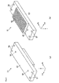
- FIG. 3 is a diagram showing the configuration of the collimator module 41.
- FIG. 3(a) is a perspective diagram of the collimator module 41 as viewed from the X-ray outgoing side
- FIG. 3(b) is a perspective diagram of the collimator module 41 as viewed from the X-ray incoming side.
- the collimator module 41 is comprised of a plurality of collimator plates 42 arranged in the CH direction, and a top side block 43 and a bottom side block 44 which support these collimator plates 42 with the collimator plates 42 interposed therebetween as viewed in the SL direction.
- a top side alignment pin 45 is provided in the neighborhood of the center of the top side block 43 as viewed in the CH direction.
- a bottom side alignment pin 46 is provided in the neighborhood of the center of the bottom side block 44 as viewed in the CH direction.
- Each of the top side and bottom side alignment pins 45 and 46 has an approximately cylindrical form that extends along the I direction.
- the top side and bottom side alignment pins 45 and 46 are press-fitted in and fixed to through holes defined in the centers of the top side and bottom side blocks 43 and 44 as viewed in the CH direction.
- Each of the collimator plates 42 is comprised of a heavy metal high in X-ray absorptivity, such as tungsten (W), molybdenum (Mo) or the like.
- the top side and bottom side blocks 43 and 44, and the top side and bottom side alignment pints 45 and 46 are comprised of, for example, stainless, aluminum or the like.
- the collimator modules 41 are configured so as to separate detecting elements corresponding to 32 cells in the CH direction.
- FIG. 4 is a diagram showing the configuration of the detector module 51.
- FIG. 4(a) is a perspective diagram of the detector module 51 as viewed from the X-ray outgoing side
- FIG. 4(b) is a perspective diagram of the detector module 51 as viewed from the X-ray incoming side.
- the detector module 51 is made up of a plurality of detecting elements 52 two-dimensionally arranged in the CH and SL directions, and a support body 53 which supports these detecting elements 52.
- a signal processing unit for processing signals outputted from the detecting elements 52 may be fixed to the support body 53.
- Top side mounting holes 56 and bottom side mounting holes 57 for mounting the collimator module 51 to the top side and bottom side rails 31 and 32 are formed at both ends in the SL direction, of the support body 53.
- Top side and bottom side alignment holes 54 and 55 into which the top side and bottom side alignment pins 45 and 46 are fitted, are formed in positions close to both ends in the SL direction, of the support body 53 and being in close proximity to the center thereof in the CH direction.
- the pitch of arrangement of the detecting elements 52 is 1mm, for example.
- the detecting element 52 is comprised of, for example, a scintillator element which emits light in response to the X-rays 13, and a photo diode which performs photoelectric conversion.
- the support body 53 is comprised of, for example, stainless, aluminum or the like.
- the detector module 51 is configured by arranging the detecting elements 52 corresponding to 32 cells in the CH direction and 64 cells in the SL direction, for example.
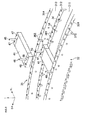
- FIG. 5 is a diagram showing the manner in which each of the collimator modules is positioned using the alignment pins. This diagram is shown as a perspective diagram taken when the top side and bottom side rails 31 and 32 are seen from the X-ray outgoing side.
- a top side first plane 311, a top side first curved plane 312, a top side second plane 313, and a top side second curved plane 314 are stepwise formed in the top side rail 31.
- a bottom side first plane 321 (not shown), a bottom side first curved plane 322 (not shown), a bottom side second plane 323 (not shown), and a bottom side second curved plane 324 are stepwise formed even in the bottom side rail 32.
- the top side and bottom side first planes 311 and 321 and the top side and bottom side second planes 313 and 323 are approximately parallel to the I direction corresponding to the X-ray radiation direction.
- top side and bottom side first planes 311 and 321 and the top side and bottom side second planes 313 and 323 both formed in the top side and bottom side rails 31 and 32 are respectively formed opposite to each other in the SL direction.
- the top side and bottom side first curved planes 312 and 322 are respectively placement surfaces on which the collimator modules 41 are placed.
- a plurality of top side and bottom side concave grooves 34 and 35 (35: not shown) in which the top side and bottom side alignment pins 45 and 46 provided in the collimator modules 41 are fitted, are formed in the top side and bottom side first planes 311 and 321 and the top side and bottom side first curved planes 312 and 322 at intervals in the CH direction.
- a plurality of top side and bottom side first threaded holes 361 and 371 (371: not shown) for fastening the collimator modules 41 with screws are respectively formed in the top side and bottom side first curved planes 312 and 322.
- a plurality of top side and bottom side second threaded holes 362 and 372 for fastening the detector modules 51 with screws are respectively formed in the top side and bottom side second curved planes 314 and 324.
- these concave grooves and threaded holes are formed by being highly accurately dug in members forming the top side rail 31 and the bottom side rail 32 with a drill or the like.
- Other parts formed with these concave grooves and threaded holes may be attached to the top side rail 31 and the bottom side rail 32, but they are preferably directly dug in the rails because high rigidity is obtained.
- Each of the collimator modules 41 is arranged in such a manner that the ends on the X-ray incoming side, of the top side and bottom side alignment pins 45 and 46 thereof are respectively fitted into the top side and bottom side concave grooves 34 and 35.
- the collimator module 41 is positioned relative to the top side rail 31 and the bottom side rail 32.
- the collimator module 41 is threadedly mounted in the top side and bottom side first threaded holes 361 and 371 in this state.
- FIG. 6 is a diagram showing the manner in which the detector module is positioned using the alignment pins. As with FIG. 5 , this diagram is shown as a perspective diagram taken when the top side and bottom side rails 31 and 32 are seen from the X-ray outgoing side.
- Each of the detector modules 51 is arranged in such a manner that the ends on the X-ray outgoing side, of the top side and bottom side alignment pins 45 and 46 are respectively fitted into the top side and bottom side alignment holes 54 and 55 of the detector module 51.
- the detector module 51 is positioned relative to the top side rail 31 and the bottom side rail 32.
- the detector module 51 is threadedly mounted in the top side and bottom side second threaded holes 362 and 372 in this state.
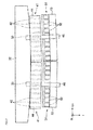
- FIG. 7 is a diagram showing the manner in which the collimator modules and the detector modules are respectively positioned relative to the rails. This diagram is shown as a diagram taken when the top side rail 31 and the bottom side rail 32 are seen in the SL direction.
- the collimator plates 42 have been designed in such a manner as to separate the detecting elements 52 in the CH direction with high accuracy.
- the collimator module 41 or the collimator plates 42 are placed even in both positions corresponding to both ends of each detecting element 53 in the detector module 51 as viewed in the CH direction, the collimator plates 42 overlap each other at a joint between the detector modules 51. Therefore, actually, the collimator module 41 is designed in such a manner that the collimator plate 42 is placed only in one of the positions corresponding to both ends of the detecting element 52 in the detector module 51 as viewed in the CH direction.
- the top side and bottom side alignment holes 54 and 55 of the detector module 51 are arranged in the center in the CH direction, of the detector module 51 because of their ease of design and so on. Therefore, the top side and bottom side alignment pins 45 and 46 of each collimator module 41 are placed in positions which are located in the neighborhood of the CH-direction center of the collimator module 41, i.e., the top side and bottom side blocks 43 and 44 and slightly shifted in the CH direction from the center thereof.
- the collimator module 41 and the detector module 51 that correspond to each other are positioned on the basis of the top side and bottom side alignment pins 45 and 46 identical to each other, the accumulation of tolerances at their positioning can be prevented, and the detecting elements 52 and the collimator plates 42 can highly accurately be aligned with each other.
- the present invention is not limited to the present embodiment, and various embodiments can be adopted within the scope not departing from the gist of the present invention.
- top side and bottom side concave grooves 34 and 35 respectively formed in the top side and bottom side first planes 311 and 321 may be provided as columnar concave holes instead of them.
- top side and bottom side alignment holes 54 and 55 formed in the detector module 51 which are fitted to the ends on the X-ray outgoing side, of the top side and bottom side alignment pins 45 and 46, may be provided as concave holes having ends instead of the through holes.
- each of the top side and bottom side alignment pins 45 and 46 may be not only a perfect circular form, but also an elliptic shape, a polygon or the like.
- the collimator module 41 may be a two-dimensional collimator module in which the collimator plates 42 are arranged in lattice form in the CH and SL directions.
- the invention is not limited to the apparatus using the X-rays, but can be applied even to an apparatus using other radiation, e.g., ⁇ (gamma) rays as in an SPECT apparatus.
- ⁇ (gamma) rays as in an SPECT apparatus.
Landscapes
- Physics & Mathematics (AREA)
- Engineering & Computer Science (AREA)
- Health & Medical Sciences (AREA)
- Life Sciences & Earth Sciences (AREA)
- High Energy & Nuclear Physics (AREA)
- Medical Informatics (AREA)
- Spectroscopy & Molecular Physics (AREA)
- General Engineering & Computer Science (AREA)
- Optics & Photonics (AREA)
- Molecular Biology (AREA)
- Biophysics (AREA)
- Pathology (AREA)
- Radiology & Medical Imaging (AREA)
- Biomedical Technology (AREA)
- Heart & Thoracic Surgery (AREA)
- Nuclear Medicine, Radiotherapy & Molecular Imaging (AREA)
- Surgery (AREA)
- Animal Behavior & Ethology (AREA)
- General Health & Medical Sciences (AREA)
- Public Health (AREA)
- Veterinary Medicine (AREA)
- Apparatus For Radiation Diagnosis (AREA)
- Measurement Of Radiation (AREA)
Applications Claiming Priority (1)
| Application Number | Priority Date | Filing Date | Title |
|---|---|---|---|
| JP2012187687A JP5815488B2 (ja) | 2012-08-28 | 2012-08-28 | 放射線検出装置および放射線撮影装置 |
Publications (3)
| Publication Number | Publication Date |
|---|---|
| EP2704155A2 true EP2704155A2 (de) | 2014-03-05 |
| EP2704155A3 EP2704155A3 (de) | 2017-02-08 |
| EP2704155B1 EP2704155B1 (de) | 2018-02-28 |
Family
ID=49033826
Family Applications (1)
| Application Number | Title | Priority Date | Filing Date |
|---|---|---|---|
| EP13180823.0A Active EP2704155B1 (de) | 2012-08-28 | 2013-08-19 | Strahlungserkennungsvorrichtung und Strahlungsabbildungsvorrichtung |
Country Status (4)
| Country | Link |
|---|---|
| US (1) | US8987675B2 (de) |
| EP (1) | EP2704155B1 (de) |
| JP (1) | JP5815488B2 (de) |
| CN (1) | CN103654825B (de) |
Families Citing this family (10)
| Publication number | Priority date | Publication date | Assignee | Title |
|---|---|---|---|---|
| US9519069B2 (en) * | 2013-09-06 | 2016-12-13 | General Electric Company | Precision self-aligning CT detector sensors |
| US10791999B2 (en) * | 2014-02-04 | 2020-10-06 | General Electric Company | Interface for gantry and component |
| EP2910189B1 (de) * | 2014-02-21 | 2016-09-14 | Samsung Electronics Co., Ltd | Röntgenrasterstruktur und röntgenvorrichtung damit |
| CN104605876A (zh) * | 2014-12-12 | 2015-05-13 | 沈阳东软医疗系统有限公司 | 一种ct机检测器模块和检测器系统 |
| KR101743469B1 (ko) * | 2015-11-12 | 2017-06-05 | 대구보건대학교산학협력단 | 엑스선 검사장치 및 방법 |
| KR101823532B1 (ko) * | 2016-01-26 | 2018-01-30 | 삼성전자주식회사 | X선 디텍터 장치 및 x선 디텍터 장치의 동작 방법 |
| JP6615666B2 (ja) * | 2016-03-24 | 2019-12-04 | キヤノンメディカルシステムズ株式会社 | 放射線検出器及び放射線検査装置 |
| US11197643B2 (en) | 2018-03-16 | 2021-12-14 | Mobius Imaging, Llc | Medical x-ray imaging systems and methods |
| JP7166833B2 (ja) | 2018-08-03 | 2022-11-08 | キヤノンメディカルシステムズ株式会社 | 放射線検出器及び放射線検出器モジュール |
| CN115624342A (zh) * | 2022-08-15 | 2023-01-20 | 无锡伽马睿电子科技有限公司 | 成像探测器及其组装方法 |
Citations (1)
| Publication number | Priority date | Publication date | Assignee | Title |
|---|---|---|---|---|
| JP2002328175A (ja) | 2000-12-29 | 2002-11-15 | Ge Medical Systems Global Technology Co Llc | 指向エネルギ・ビームで溶接したct検出器コリメータ |
Family Cites Families (23)
| Publication number | Priority date | Publication date | Assignee | Title |
|---|---|---|---|---|
| US4203037A (en) | 1977-08-01 | 1980-05-13 | University Of Pittsburgh | Collimated radiation apparatus |
| JPS60165571A (ja) | 1984-02-09 | 1985-08-28 | Toshiba Corp | コリメ−タの着脱機構 |
| CN1139872A (zh) * | 1994-02-03 | 1997-01-08 | 模拟公司 | 层析x射线照相装置的模式化检测装置 |
| WO1995021515A1 (en) * | 1994-02-03 | 1995-08-10 | Analogic Corporation | X-ray tomography system for and method of improving the quality of a scanned image |
| US5668851A (en) * | 1996-06-21 | 1997-09-16 | Analogic Corporation | X-ray Tomography system with stabilized detector response |
| US6052436A (en) | 1997-07-16 | 2000-04-18 | Bionix Development Corporation | Radiation therapy device employing cam pin and cam groove guiding system for controlling movement of linear multi-leaf collimator leaves |
| JP4476471B2 (ja) * | 2000-11-27 | 2010-06-09 | 株式会社東芝 | X線コンピュータ断層撮影装置 |
| US6982423B2 (en) * | 2001-11-20 | 2006-01-03 | Koninklijke Philips Electronics N.V. | CT detector-module having radiation shielding for the processing circuitry |
| JP4184701B2 (ja) | 2002-04-19 | 2008-11-19 | エスアイアイ・ナノテクノロジー株式会社 | 放射線検出器 |
| US7177387B2 (en) * | 2003-11-29 | 2007-02-13 | General Electric Company | Self-aligning scintillator-collimator assembly |
| US7525097B2 (en) * | 2004-04-06 | 2009-04-28 | Koninklijke Philips Electronics N.V. | Modular device for the detection and/or transmission of radiation with self-aligning modules |
| US7560702B2 (en) * | 2005-11-28 | 2009-07-14 | General Electric Company | Interconnect and packaging method for multi-slice CT detector modules |
| DE102006051146B4 (de) | 2006-10-30 | 2009-06-10 | Siemens Ag | Kollimatorlamellenausrichtungsmittel, Kollimatorlamellenausrichtungsvorrichtung und Verfahren zur Herstellung eines Strahlungskollimators |
| JP4901919B2 (ja) * | 2009-07-13 | 2012-03-21 | 株式会社東芝 | X線コンピュータ断層撮影装置及びx線検出装置製造方法 |
| JP5610461B2 (ja) * | 2009-10-23 | 2014-10-22 | ジーイー・メディカル・システムズ・グローバル・テクノロジー・カンパニー・エルエルシー | コリメータモジュール、x線検出器及びx線ct装置 |
| DE102009056722B3 (de) | 2009-12-02 | 2011-05-12 | Siemens Aktiengesellschaft | Kollimatormodul zum modularen Aufbau eines Kollimators für einen Strahlendetektor und Strahlendetektor |
| JP5836011B2 (ja) * | 2010-09-22 | 2015-12-24 | 株式会社東芝 | X線CT(ComputedTomography)装置、放射線検出器及びその製造方法 |
| DE102010062192B3 (de) * | 2010-11-30 | 2012-06-06 | Siemens Aktiengesellschaft | 2D-Kollimator für einen Strahlendetektor und Verfahren zur Herstellung eines solchen 2D-Kollimators |
| JP2012137443A (ja) * | 2010-12-28 | 2012-07-19 | Ge Medical Systems Global Technology Co Llc | 2次元コリメータモジュール、x線検出器、x線ct装置、2次元コリメータモジュールの組立て方法、および2次元コリメータ装置の製造方法 |
| CN102686162A (zh) * | 2011-01-07 | 2012-09-19 | 株式会社东芝 | 准直仪及x射线计算机断层摄影装置 |
| DE102011087211B4 (de) * | 2011-11-28 | 2019-06-27 | Siemens Healthcare Gmbh | Detektoranordnung eines ionisierende Strahlung detektierenden Detektors eines bildgebenden Systems mit Luftkühlung und Verfahren zur Kühlung der Detektoranordnung |
| US8890079B2 (en) * | 2012-06-29 | 2014-11-18 | General Electric Company | Radiation detection device and radiation tomographic apparatus, and method for assembling radiation detection device |
| CN202920221U (zh) * | 2012-11-13 | 2013-05-08 | 上海联影医疗科技有限公司 | 探测器组件及x射线设备 |
-
2012
- 2012-08-28 JP JP2012187687A patent/JP5815488B2/ja active Active
-
2013
- 2013-08-19 EP EP13180823.0A patent/EP2704155B1/de active Active
- 2013-08-27 US US14/011,477 patent/US8987675B2/en active Active
- 2013-08-28 CN CN201310380294.0A patent/CN103654825B/zh active Active
Patent Citations (1)
| Publication number | Priority date | Publication date | Assignee | Title |
|---|---|---|---|---|
| JP2002328175A (ja) | 2000-12-29 | 2002-11-15 | Ge Medical Systems Global Technology Co Llc | 指向エネルギ・ビームで溶接したct検出器コリメータ |
Also Published As
| Publication number | Publication date |
|---|---|
| CN103654825B (zh) | 2017-08-08 |
| EP2704155B1 (de) | 2018-02-28 |
| JP5815488B2 (ja) | 2015-11-17 |
| JP2014042732A (ja) | 2014-03-13 |
| US8987675B2 (en) | 2015-03-24 |
| CN103654825A (zh) | 2014-03-26 |
| US20140064443A1 (en) | 2014-03-06 |
| EP2704155A3 (de) | 2017-02-08 |
Similar Documents
| Publication | Publication Date | Title |
|---|---|---|
| EP2704155B1 (de) | Strahlungserkennungsvorrichtung und Strahlungsabbildungsvorrichtung | |
| KR102047391B1 (ko) | 콜리메이터 플레이트, 콜리메이터 모듈, 방사선 검출기, 방사선 투과 검사 장치 및 콜리메이터 모듈 조립 방법 | |
| US8890079B2 (en) | Radiation detection device and radiation tomographic apparatus, and method for assembling radiation detection device | |
| US8571176B2 (en) | Methods and apparatus for collimation of detectors | |
| EP2662023A1 (de) | Kollimator und röntgenberechnete tomographievorrichtung | |
| JP5758304B2 (ja) | X線検出器及びx線ct装置 | |
| EP3060128B1 (de) | Röntgensystem, insbesondere tomosynthesesysteme und verfahren zur aufnahme eines bildes eines gegenstandes. | |
| US20150162107A1 (en) | Collimator module manufacturing method, collimator module, radiation detection device, and radiation imaging device | |
| US20140219415A1 (en) | Adjustable photon detection systems for multi-slice x-ray computed tomography systems | |
| JP2013190310A (ja) | X線検出器、x線検出器の製造方法及びx線ct装置 | |
| JP5943758B2 (ja) | コリメータモジュール、放射線検出装置および放射線断層撮影装置 | |
| JP6310703B2 (ja) | 放射線検出器とそれを用いたx線ct装置 | |
| JP7166833B2 (ja) | 放射線検出器及び放射線検出器モジュール | |
| US9826944B2 (en) | Radiation detector and X-ray CT apparatus provided therewith | |
| JP6818592B2 (ja) | コリメータ、放射線検出器、及び放射線検査装置 | |
| JP2015137882A5 (de) | ||
| CN103957804A (zh) | X射线ct装置以及x射线ct装置用的数据检测系统 | |
| JP6523451B2 (ja) | 放射線検出器とそれを備えたx線ct装置 | |
| JP5809499B2 (ja) | 2次元コリメータモジュール、放射線検出器、x線ct装置、2次元コリメータモジュールの組立て方法、および2次元コリメータ装置の製造方法。 | |
| CN224008403U (zh) | 辐射检测器模块以及成像设备 | |
| CN222439422U (zh) | 一种拼接式探测器、探测器模组以及静态ct系统 | |
| JPWO2015182493A1 (ja) | X線ct装置 | |
| JP2017205257A (ja) | タルボ撮影装置 |
Legal Events
| Date | Code | Title | Description |
|---|---|---|---|
| AK | Designated contracting states |
Kind code of ref document: A2 Designated state(s): AL AT BE BG CH CY CZ DE DK EE ES FI FR GB GR HR HU IE IS IT LI LT LU LV MC MK MT NL NO PL PT RO RS SE SI SK SM TR |
|
| AX | Request for extension of the european patent |
Extension state: BA ME |
|
| PUAI | Public reference made under article 153(3) epc to a published international application that has entered the european phase |
Free format text: ORIGINAL CODE: 0009012 |
|
| PUAL | Search report despatched |
Free format text: ORIGINAL CODE: 0009013 |
|
| AK | Designated contracting states |
Kind code of ref document: A3 Designated state(s): AL AT BE BG CH CY CZ DE DK EE ES FI FR GB GR HR HU IE IS IT LI LT LU LV MC MK MT NL NO PL PT RO RS SE SI SK SM TR |
|
| AX | Request for extension of the european patent |
Extension state: BA ME |
|
| RIC1 | Information provided on ipc code assigned before grant |
Ipc: A61B 6/00 20060101ALI20170102BHEP Ipc: G21K 1/02 20060101AFI20170102BHEP |
|
| 17P | Request for examination filed |
Effective date: 20170808 |
|
| RBV | Designated contracting states (corrected) |
Designated state(s): AL AT BE BG CH CY CZ DE DK EE ES FI FR GB GR HR HU IE IS IT LI LT LU LV MC MK MT NL NO PL PT RO RS SE SI SK SM TR |
|
| GRAP | Despatch of communication of intention to grant a patent |
Free format text: ORIGINAL CODE: EPIDOSNIGR1 |
|
| INTG | Intention to grant announced |
Effective date: 20171215 |
|
| GRAS | Grant fee paid |
Free format text: ORIGINAL CODE: EPIDOSNIGR3 |
|
| GRAA | (expected) grant |
Free format text: ORIGINAL CODE: 0009210 |
|
| AK | Designated contracting states |
Kind code of ref document: B1 Designated state(s): AL AT BE BG CH CY CZ DE DK EE ES FI FR GB GR HR HU IE IS IT LI LT LU LV MC MK MT NL NO PL PT RO RS SE SI SK SM TR |
|
| REG | Reference to a national code |
Ref country code: GB Ref legal event code: FG4D Ref country code: CH Ref legal event code: EP |
|
| REG | Reference to a national code |
Ref country code: AT Ref legal event code: REF Ref document number: 974969 Country of ref document: AT Kind code of ref document: T Effective date: 20180315 |
|
| REG | Reference to a national code |
Ref country code: IE Ref legal event code: FG4D |
|
| REG | Reference to a national code |
Ref country code: DE Ref legal event code: R096 Ref document number: 602013033634 Country of ref document: DE |
|
| REG | Reference to a national code |
Ref country code: NL Ref legal event code: MP Effective date: 20180228 |
|
| REG | Reference to a national code |
Ref country code: LT Ref legal event code: MG4D |
|
| REG | Reference to a national code |
Ref country code: AT Ref legal event code: MK05 Ref document number: 974969 Country of ref document: AT Kind code of ref document: T Effective date: 20180228 |
|
| PG25 | Lapsed in a contracting state [announced via postgrant information from national office to epo] |
Ref country code: FI Free format text: LAPSE BECAUSE OF FAILURE TO SUBMIT A TRANSLATION OF THE DESCRIPTION OR TO PAY THE FEE WITHIN THE PRESCRIBED TIME-LIMIT Effective date: 20180228 Ref country code: LT Free format text: LAPSE BECAUSE OF FAILURE TO SUBMIT A TRANSLATION OF THE DESCRIPTION OR TO PAY THE FEE WITHIN THE PRESCRIBED TIME-LIMIT Effective date: 20180228 Ref country code: NL Free format text: LAPSE BECAUSE OF FAILURE TO SUBMIT A TRANSLATION OF THE DESCRIPTION OR TO PAY THE FEE WITHIN THE PRESCRIBED TIME-LIMIT Effective date: 20180228 Ref country code: CY Free format text: LAPSE BECAUSE OF FAILURE TO SUBMIT A TRANSLATION OF THE DESCRIPTION OR TO PAY THE FEE WITHIN THE PRESCRIBED TIME-LIMIT Effective date: 20180228 Ref country code: ES Free format text: LAPSE BECAUSE OF FAILURE TO SUBMIT A TRANSLATION OF THE DESCRIPTION OR TO PAY THE FEE WITHIN THE PRESCRIBED TIME-LIMIT Effective date: 20180228 Ref country code: HR Free format text: LAPSE BECAUSE OF FAILURE TO SUBMIT A TRANSLATION OF THE DESCRIPTION OR TO PAY THE FEE WITHIN THE PRESCRIBED TIME-LIMIT Effective date: 20180228 Ref country code: NO Free format text: LAPSE BECAUSE OF FAILURE TO SUBMIT A TRANSLATION OF THE DESCRIPTION OR TO PAY THE FEE WITHIN THE PRESCRIBED TIME-LIMIT Effective date: 20180528 |
|
| PG25 | Lapsed in a contracting state [announced via postgrant information from national office to epo] |
Ref country code: RS Free format text: LAPSE BECAUSE OF FAILURE TO SUBMIT A TRANSLATION OF THE DESCRIPTION OR TO PAY THE FEE WITHIN THE PRESCRIBED TIME-LIMIT Effective date: 20180228 Ref country code: BG Free format text: LAPSE BECAUSE OF FAILURE TO SUBMIT A TRANSLATION OF THE DESCRIPTION OR TO PAY THE FEE WITHIN THE PRESCRIBED TIME-LIMIT Effective date: 20180528 Ref country code: AT Free format text: LAPSE BECAUSE OF FAILURE TO SUBMIT A TRANSLATION OF THE DESCRIPTION OR TO PAY THE FEE WITHIN THE PRESCRIBED TIME-LIMIT Effective date: 20180228 Ref country code: GR Free format text: LAPSE BECAUSE OF FAILURE TO SUBMIT A TRANSLATION OF THE DESCRIPTION OR TO PAY THE FEE WITHIN THE PRESCRIBED TIME-LIMIT Effective date: 20180529 Ref country code: LV Free format text: LAPSE BECAUSE OF FAILURE TO SUBMIT A TRANSLATION OF THE DESCRIPTION OR TO PAY THE FEE WITHIN THE PRESCRIBED TIME-LIMIT Effective date: 20180228 Ref country code: SE Free format text: LAPSE BECAUSE OF FAILURE TO SUBMIT A TRANSLATION OF THE DESCRIPTION OR TO PAY THE FEE WITHIN THE PRESCRIBED TIME-LIMIT Effective date: 20180228 |
|
| PG25 | Lapsed in a contracting state [announced via postgrant information from national office to epo] |
Ref country code: AL Free format text: LAPSE BECAUSE OF FAILURE TO SUBMIT A TRANSLATION OF THE DESCRIPTION OR TO PAY THE FEE WITHIN THE PRESCRIBED TIME-LIMIT Effective date: 20180228 Ref country code: PL Free format text: LAPSE BECAUSE OF FAILURE TO SUBMIT A TRANSLATION OF THE DESCRIPTION OR TO PAY THE FEE WITHIN THE PRESCRIBED TIME-LIMIT Effective date: 20180228 Ref country code: IT Free format text: LAPSE BECAUSE OF FAILURE TO SUBMIT A TRANSLATION OF THE DESCRIPTION OR TO PAY THE FEE WITHIN THE PRESCRIBED TIME-LIMIT Effective date: 20180228 Ref country code: RO Free format text: LAPSE BECAUSE OF FAILURE TO SUBMIT A TRANSLATION OF THE DESCRIPTION OR TO PAY THE FEE WITHIN THE PRESCRIBED TIME-LIMIT Effective date: 20180228 Ref country code: EE Free format text: LAPSE BECAUSE OF FAILURE TO SUBMIT A TRANSLATION OF THE DESCRIPTION OR TO PAY THE FEE WITHIN THE PRESCRIBED TIME-LIMIT Effective date: 20180228 |
|
| REG | Reference to a national code |
Ref country code: DE Ref legal event code: R097 Ref document number: 602013033634 Country of ref document: DE |
|
| PG25 | Lapsed in a contracting state [announced via postgrant information from national office to epo] |
Ref country code: SK Free format text: LAPSE BECAUSE OF FAILURE TO SUBMIT A TRANSLATION OF THE DESCRIPTION OR TO PAY THE FEE WITHIN THE PRESCRIBED TIME-LIMIT Effective date: 20180228 Ref country code: CZ Free format text: LAPSE BECAUSE OF FAILURE TO SUBMIT A TRANSLATION OF THE DESCRIPTION OR TO PAY THE FEE WITHIN THE PRESCRIBED TIME-LIMIT Effective date: 20180228 Ref country code: SM Free format text: LAPSE BECAUSE OF FAILURE TO SUBMIT A TRANSLATION OF THE DESCRIPTION OR TO PAY THE FEE WITHIN THE PRESCRIBED TIME-LIMIT Effective date: 20180228 Ref country code: DK Free format text: LAPSE BECAUSE OF FAILURE TO SUBMIT A TRANSLATION OF THE DESCRIPTION OR TO PAY THE FEE WITHIN THE PRESCRIBED TIME-LIMIT Effective date: 20180228 |
|
| PLBE | No opposition filed within time limit |
Free format text: ORIGINAL CODE: 0009261 |
|
| STAA | Information on the status of an ep patent application or granted ep patent |
Free format text: STATUS: NO OPPOSITION FILED WITHIN TIME LIMIT |
|
| 26N | No opposition filed |
Effective date: 20181129 |
|
| PG25 | Lapsed in a contracting state [announced via postgrant information from national office to epo] |
Ref country code: SI Free format text: LAPSE BECAUSE OF FAILURE TO SUBMIT A TRANSLATION OF THE DESCRIPTION OR TO PAY THE FEE WITHIN THE PRESCRIBED TIME-LIMIT Effective date: 20180228 |
|
| PG25 | Lapsed in a contracting state [announced via postgrant information from national office to epo] |
Ref country code: MC Free format text: LAPSE BECAUSE OF FAILURE TO SUBMIT A TRANSLATION OF THE DESCRIPTION OR TO PAY THE FEE WITHIN THE PRESCRIBED TIME-LIMIT Effective date: 20180228 |
|
| REG | Reference to a national code |
Ref country code: CH Ref legal event code: PL |
|
| GBPC | Gb: european patent ceased through non-payment of renewal fee |
Effective date: 20180819 |
|
| PG25 | Lapsed in a contracting state [announced via postgrant information from national office to epo] |
Ref country code: CH Free format text: LAPSE BECAUSE OF NON-PAYMENT OF DUE FEES Effective date: 20180831 Ref country code: LI Free format text: LAPSE BECAUSE OF NON-PAYMENT OF DUE FEES Effective date: 20180831 Ref country code: LU Free format text: LAPSE BECAUSE OF NON-PAYMENT OF DUE FEES Effective date: 20180819 |
|
| REG | Reference to a national code |
Ref country code: BE Ref legal event code: MM Effective date: 20180831 |
|
| REG | Reference to a national code |
Ref country code: IE Ref legal event code: MM4A |
|
| PG25 | Lapsed in a contracting state [announced via postgrant information from national office to epo] |
Ref country code: IE Free format text: LAPSE BECAUSE OF NON-PAYMENT OF DUE FEES Effective date: 20180819 |
|
| PG25 | Lapsed in a contracting state [announced via postgrant information from national office to epo] |
Ref country code: FR Free format text: LAPSE BECAUSE OF NON-PAYMENT OF DUE FEES Effective date: 20180831 Ref country code: BE Free format text: LAPSE BECAUSE OF NON-PAYMENT OF DUE FEES Effective date: 20180831 |
|
| PG25 | Lapsed in a contracting state [announced via postgrant information from national office to epo] |
Ref country code: GB Free format text: LAPSE BECAUSE OF NON-PAYMENT OF DUE FEES Effective date: 20180819 |
|
| PG25 | Lapsed in a contracting state [announced via postgrant information from national office to epo] |
Ref country code: MT Free format text: LAPSE BECAUSE OF NON-PAYMENT OF DUE FEES Effective date: 20180819 |
|
| PG25 | Lapsed in a contracting state [announced via postgrant information from national office to epo] |
Ref country code: TR Free format text: LAPSE BECAUSE OF FAILURE TO SUBMIT A TRANSLATION OF THE DESCRIPTION OR TO PAY THE FEE WITHIN THE PRESCRIBED TIME-LIMIT Effective date: 20180228 |
|
| PG25 | Lapsed in a contracting state [announced via postgrant information from national office to epo] |
Ref country code: PT Free format text: LAPSE BECAUSE OF FAILURE TO SUBMIT A TRANSLATION OF THE DESCRIPTION OR TO PAY THE FEE WITHIN THE PRESCRIBED TIME-LIMIT Effective date: 20180228 Ref country code: HU Free format text: LAPSE BECAUSE OF FAILURE TO SUBMIT A TRANSLATION OF THE DESCRIPTION OR TO PAY THE FEE WITHIN THE PRESCRIBED TIME-LIMIT; INVALID AB INITIO Effective date: 20130819 |
|
| PG25 | Lapsed in a contracting state [announced via postgrant information from national office to epo] |
Ref country code: MK Free format text: LAPSE BECAUSE OF NON-PAYMENT OF DUE FEES Effective date: 20180228 |
|
| PG25 | Lapsed in a contracting state [announced via postgrant information from national office to epo] |
Ref country code: IS Free format text: LAPSE BECAUSE OF FAILURE TO SUBMIT A TRANSLATION OF THE DESCRIPTION OR TO PAY THE FEE WITHIN THE PRESCRIBED TIME-LIMIT Effective date: 20180628 |
|
| P01 | Opt-out of the competence of the unified patent court (upc) registered |
Effective date: 20230528 |
|
| PGFP | Annual fee paid to national office [announced via postgrant information from national office to epo] |
Ref country code: DE Payment date: 20250724 Year of fee payment: 13 |