EP2701475A1 - Boîtier destiné à la réception d'un écran plat - Google Patents
Boîtier destiné à la réception d'un écran plat Download PDFInfo
- Publication number
- EP2701475A1 EP2701475A1 EP12181373.7A EP12181373A EP2701475A1 EP 2701475 A1 EP2701475 A1 EP 2701475A1 EP 12181373 A EP12181373 A EP 12181373A EP 2701475 A1 EP2701475 A1 EP 2701475A1
- Authority
- EP
- European Patent Office
- Prior art keywords
- frame
- housing
- flat
- heat
- profile element
- Prior art date
- Legal status (The legal status is an assumption and is not a legal conclusion. Google has not performed a legal analysis and makes no representation as to the accuracy of the status listed.)
- Withdrawn
Links
Images


Classifications
-
- H—ELECTRICITY
- H05—ELECTRIC TECHNIQUES NOT OTHERWISE PROVIDED FOR
- H05K—PRINTED CIRCUITS; CASINGS OR CONSTRUCTIONAL DETAILS OF ELECTRIC APPARATUS; MANUFACTURE OF ASSEMBLAGES OF ELECTRICAL COMPONENTS
- H05K7/00—Constructional details common to different types of electric apparatus
- H05K7/20—Modifications to facilitate cooling, ventilating, or heating
- H05K7/2039—Modifications to facilitate cooling, ventilating, or heating characterised by the heat transfer by conduction from the heat generating element to a dissipating body
-
- G—PHYSICS
- G06—COMPUTING; CALCULATING OR COUNTING
- G06F—ELECTRIC DIGITAL DATA PROCESSING
- G06F1/00—Details not covered by groups G06F3/00 - G06F13/00 and G06F21/00
- G06F1/16—Constructional details or arrangements
- G06F1/1601—Constructional details related to the housing of computer displays, e.g. of CRT monitors, of flat displays
-
- G—PHYSICS
- G06—COMPUTING; CALCULATING OR COUNTING
- G06F—ELECTRIC DIGITAL DATA PROCESSING
- G06F1/00—Details not covered by groups G06F3/00 - G06F13/00 and G06F21/00
- G06F1/16—Constructional details or arrangements
- G06F1/20—Cooling means
-
- H—ELECTRICITY
- H05—ELECTRIC TECHNIQUES NOT OTHERWISE PROVIDED FOR
- H05K—PRINTED CIRCUITS; CASINGS OR CONSTRUCTIONAL DETAILS OF ELECTRIC APPARATUS; MANUFACTURE OF ASSEMBLAGES OF ELECTRICAL COMPONENTS
- H05K5/00—Casings, cabinets or drawers for electric apparatus
- H05K5/02—Details
-
- H—ELECTRICITY
- H05—ELECTRIC TECHNIQUES NOT OTHERWISE PROVIDED FOR
- H05K—PRINTED CIRCUITS; CASINGS OR CONSTRUCTIONAL DETAILS OF ELECTRIC APPARATUS; MANUFACTURE OF ASSEMBLAGES OF ELECTRICAL COMPONENTS
- H05K7/00—Constructional details common to different types of electric apparatus
- H05K7/18—Construction of rack or frame
-
- H—ELECTRICITY
- H05—ELECTRIC TECHNIQUES NOT OTHERWISE PROVIDED FOR
- H05K—PRINTED CIRCUITS; CASINGS OR CONSTRUCTIONAL DETAILS OF ELECTRIC APPARATUS; MANUFACTURE OF ASSEMBLAGES OF ELECTRICAL COMPONENTS
- H05K7/00—Constructional details common to different types of electric apparatus
- H05K7/20—Modifications to facilitate cooling, ventilating, or heating
- H05K7/20954—Modifications to facilitate cooling, ventilating, or heating for display panels
- H05K7/20963—Heat transfer by conduction from internal heat source to heat radiating structure
-
- Y—GENERAL TAGGING OF NEW TECHNOLOGICAL DEVELOPMENTS; GENERAL TAGGING OF CROSS-SECTIONAL TECHNOLOGIES SPANNING OVER SEVERAL SECTIONS OF THE IPC; TECHNICAL SUBJECTS COVERED BY FORMER USPC CROSS-REFERENCE ART COLLECTIONS [XRACs] AND DIGESTS
- Y10—TECHNICAL SUBJECTS COVERED BY FORMER USPC
- Y10T—TECHNICAL SUBJECTS COVERED BY FORMER US CLASSIFICATION
- Y10T29/00—Metal working
- Y10T29/49—Method of mechanical manufacture
- Y10T29/49826—Assembling or joining
Definitions
- the present invention relates to a housing for receiving a flat screen, a method for producing such a housing and a device having such a housing and a flat screen recorded therein.
- Such housings are commonly used in the installation of flat panel displays in public places and especially in vehicles as installation and protection device for the flat screen.
- flat panel displays are often installed to provide information to a relevant public or to entertain people.
- This can be LCD, TFT, FED or LED screens, but also plasma screens or other types of flat screens are used.
- LCD, TFT, FED or LED screens are usually provided per vehicle to display the passengers, for example, current timetables, safety information or news from world events.
- To attach the flat screens and protect against external mechanical damage they are usually housed in a housing. The housing with the flat screen received therein is then fastened to or in a building or vehicle, etc., at a suitable location which is easily visible to the corresponding public.
- a housing of the type described above is for example in the US 7,619,881 described.
- a housing is proposed, as indicated in claim 1.
- a method for producing such a housing is specified in claim 12.
- a further object of the present invention is to provide a housing for receiving a flat screen, in which the dissipation of the heat generated in the flat screen to the outside at any time to a sufficient extent is guaranteed.
- a housing is proposed, as indicated in claim 9.
- a device which has a housing and a flat screen recorded therein.
- Advantageous embodiments of the invention are specified in the dependent claims.
- the present invention thus provides a housing for receiving a flat screen, with a frame which limits a housing interior for receiving the flat screen.
- the frame is made of a particular extruded flat profile element having a plurality of predetermined bending points, which serve to define the corner regions of the frame.
- the frame of the housing surrounds the interior of the housing laterally, that is to say on that side of the flat screen accommodated in the housing, which extends perpendicular to the display surface of the screen.
- the frame is made of a flat profile element with correspondingly provided predetermined bending points.
- the frame and thus the housing are extremely simple and inexpensive to produce and especially in the production very easy to adapt to any types and sizes of flat screens.
- the generally one-piece flat profile element is preferably made of a metal, and particularly preferably made of aluminum.
- the weight of the housing is thus about 40% lower compared to a corresponding housing made of cast aluminum.
- the thermal conductivity of aluminum profiles and in particular of extruded aluminum profiles is considerably better than that of cast aluminum.
- the flat screen can in particular be an LCD, TFT, FED or LED screen or even a plasma screen.
- the flat screen can be referred to in particular as a display panel, a display or a monitor.
- the flat screen compared to its other dimensions a relatively much smaller thickness, measured in a direction perpendicular to the display surface direction.
- a flat profile element is selected whose width is approximately equal to or slightly larger than the thickness of the flat screen to be accommodated in the housing.
- the thickness of the flat screen here and in the following means in each case that dimension which extends perpendicularly to the display surface of the screen.
- the flat profile element In the production of the frame is usually adjusted in a first step, the flat profile element with respect to its length to the peripheral length of the flat panel, so that later preferably results in a frame which is designed such that it the flat screen laterally to a large extent, in particular preferably substantially completely surrounds.
- the length of the flat profile element thus preferably corresponds approximately to the circumferential length of the flat screen.
- a plurality of, in particular exactly three or exactly four, predetermined bending points are then generally provided along the longitudinal direction of the flat profile element in order to determine the positions of the corner regions of the later frame.
- the distances of the various predetermined bending points to each other along the longitudinal direction of the flat profile element advantageously correspond approximately to the side lengths of the flat screen.
- the flat profile element can then in the areas of the predetermined bending points preferably bent by more than 80 ° and less than 100 °, in particular by approximately 90 °, so that an advantageous rectangular, suitable for receiving the flat screen frame is formed.
- further steps may be taken in the manufacture of the frame.
- bores, recesses and grooves can be provided on the flat profile element.
- Location and direction information such as above, below, front, rear, above, below, inward and outward refer in the following each in a proper manner, for example, on or in a vehicle or on or in a building mounted housing with a flat screen received therein, in which the display surface faces forward and extends approximately parallel to the direction of gravity, so that an upright observer has an optimal view of the flat-panel display arranged at eye level.
- the predetermined bending points are each defined by a dilution of material at the appropriate location.
- the material dilution can be produced in any desired manner, such as, in particular, by means of a machining process, for example milling, and extends advantageously, but not necessarily, essentially over the entire width of the flat profile element and in particular substantially into a relative one to the longitudinal direction perpendicular direction.
- the predetermined bending points are each defined by a material dilution
- the bending of the flat profile element can be made into a frame in a particularly simple and precise manner, with a relatively small amount of force.
- the material dilutions are advantageously provided in the form of depressions on that side of the flat profile element, which forms the side facing the housing interior in the finished frame produced.
- the flat profile element is in each case preferably diluted by at least half, more preferably by at least two thirds, and most preferably by at least three quarters of the material thickness.
- the material dilutions are preferably each formed by a groove, which is a can have any shape.
- the groove may for example be designed in particular V-shaped or U-shaped.
- the groove is configured as a hybrid of a V-shaped and a U-shaped groove.
- a groove according to such a hybrid form is bounded by two planar surfaces and a curved surface arranged therebetween.
- Such a configured groove forms a clearly defined predetermined bending point, which allows a simple and precise bending of the flat profile element at the appropriate location. The bending then takes place in particular in the region of the curved surface of the groove.
- the radius of the arcuate surface is at least one twelfth, more preferably at least one tenth, and most preferably at least one eighth of the thickness of the flat profile element.
- the two flat surfaces of the groove form an angle of more than 60 ° and less than 120 °, in particular more than 80 ° and less than 100 °. Most advantageously, however, they include an angle of approximately 90 °.
- the two planar surfaces of the groove then preferably extend substantially parallel to one another and, in particular, are preferably adjacent to one another.
- the frame preferably forms a substantially closed rectangle whose side lengths are advantageously approximately in a ratio of 4: 3, 15: 9, 16: 9 or 16:10 to each other.
- the frame may in particular have a connection point, in which the two ends of the flat profile element are interconnected.
- the frame is thus designed such that it encloses a flat screen received in the housing substantially completely laterally in the circumferential direction.
- a connection plate can be provided, by means of which the two ends of the flat profile element are connected to one another.
- This connection plate is preferably fastened on the outside of the frame.
- the two end surfaces of the flat profile element in the longitudinal direction can abut each other, but need not.
- connection point is advantageously arranged in the vicinity of one of the corner regions of the frame.
- the connection point but in particular also form one of the corner regions of the frame.
- the frame has a recess which serves to receive an electronic component, and which is arranged in particular in the region of the connection point. Preferably, this recess is laterally completely surrounded by the material of the frame.
- the two ends of the flat profile element bound the recess together.
- both ends of the flat profile element advantageously each have an opening which is open towards the outside in the longitudinal direction of the flat profile element.
- the electronic component may in particular be a printed circuit board which may have display elements such as LEDs and sensors which serve, for example, to display the operating state of the flat screen and to measure the brightness conditions in the surroundings.
- the frame may have correspondingly arranged bores which extend from an inner surface bounding the recess to a surface of the frame facing towards the front.
- notches may also be provided on the frame in the region of the recess, which notches serve to hold the printed circuit board in the recess.
- laterally protruding projections of the printed circuit board which in particular each have the shape of a pin, can then be inserted into the indentations in order to hold the printed circuit board in the recess.
- the indentations may be designed to be open, in particular to the recess and preferably also to the side on which a connecting plate is attached to the frame. By attaching the connecting plate to the frame, the indentations are then preferably closed to the corresponding side, so that an inserted with their lateral projections in the notches printed circuit board is held in the housing.
- the housing has a rear wall, which serves for closing the laterally limited by the frame housing interior on the back.
- at least one connecting tab is attached to the rear wall, which is for fastening the Rear wall on the frame is used.
- the one or more connecting straps are advantageously attached to the rear wall substantially along the entire circumference such that they protrude substantially perpendicularly therefrom.
- the rear wall, together with the connecting straps attached thereto is made in one piece from a metal sheet, in particular an aluminum sheet.
- the connection of the connecting straps to the frame can in particular be effected by means of screws, which advantageously have a certain clearance before being tightened in corresponding connection bores of the frame provided for this purpose.
- the disassembly and reassembly of the housing, for example, for repair can then be done in a simple manner, and it can be ensured that the rear wall at any time rests against the back of the housed in the housing flat panel.
- the present invention also provides a housing which can be designed as described above, serves to receive a flat screen and has a frame which delimits a housing interior for receiving the flat screen, and at least one heat-dissipating element, which on the inside of the frame is mounted, and which for transferring heat, which arises in the housing interior, serves on the frame.
- the frame has on its side facing the housing interior side an inner groove into which the heat dissipating element is inserted.
- the flat screen accommodated therein can be clamped in particular between the heat-dissipating element and, for example, a rear wall of the housing. In this way it can be ensured that the flat screen is in contact with the heat-dissipating element at all times, whereby the dissipation of the heat arising in the flat screen is ensured.
- the heat-dissipating element can be any element projecting from the frame into the interior of the housing, which element is preferably made of a metal, in particular aluminum.
- the heat-dissipating element is preferably designed as a strip which is inserted along one of its longitudinal sides into the inner groove.
- the heat dissipating member may be press-fitted into the inner groove and / or fixed in the inner groove by means of an adhesive or other fastener such as screws.
- the inner groove and in particular also the heat-dissipating element extend along the entire circumference of the housing interior bounded by the frame.
- the heat-dissipating element may also extend only over a part of the circumference and in particular may be provided only along an upper longitudinal side of the frame.
- the housing also has a front window, which may be glued to the heat-dissipating element and in particular to its forwardly facing side.
- the heat dissipating element is then advantageously arranged between the flat screen and the front screen, which is generally used to protect the display surface of the flat screen.
- the housing may also have a front panel, which is preferably screwed to the frame and is advantageously configured such that it completely covers the heat-dissipating element towards the front of the viewer.
- a housing which is formed according to the above statements, is overall very simple and inexpensive to produce, and the dissipation of heat generated in the housing can be ensured at any time in a simple manner.
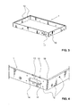
- FIG. 1 and 2 is a housing according to a first embodiment of the invention, shown for receiving a flat screen.
- the housing has a housing interior 8, which is suitable for receiving a flat screen, and which is bounded laterally by a frame 1, forward through a windscreen 4 and to the rear by a rear wall 5.
- a front panel 2 is attached to the frame 1, which has a large, rectangular opening through which the display area or the display of the recorded in the housing screen is visible.
- a plurality of connecting straps 21 are mounted on the back of the front panel 2, which abut in the assembled state of the housing on the outside of the frame 1.
- the connecting straps 21 each have bores which correspond with connecting bores 12 of the frame 1 in order to allow screw connections between the front panel 2 and the frame 1.
- a plurality of bores 22 are provided, which are used for fastening the front panel 2 for example, on or in a vehicle or building.
- the front panel 2 also has recesses 23, which allow the user to view an LED display arranged behind it.
- the LED display whose arrangement is explained in more detail below in the housing, for example, serve to display the operating status or the concern of a mains voltage on the flat screen. Behind the recesses 23 but also sensors can be arranged, which can serve for example for measuring the ambient brightness.
- a control circuit module 6 is mounted in the present embodiment, which has a separate housing with respect to the housing for the flat screen, which, for example, for receiving a Control circuit for controlling the flat screen is used.
- the rear wall 5 and the control circuit module 6 each have at least one corresponding recess, which serves to pass through cable strands or control lines.
- the control circuit module 6 has on its outer side terminals 61 to supply the control circuit module 6, for example, with a mains voltage or to connect to a data communication cable.
- the electronic components for controlling the flat screen are housed in a separate housing of the control circuit module 6, the air spaces, as far as the heat development of the flat panel and the electronic control, are substantially completely separated from each other, so that the respective heat generated independently can be dissipated.
- the design of the frame 1 is particularly in the FIGS. 3 to 6 good to see.
- the frame 1 is made of a simple flat profile element, which in turn can be made by simply extruding a metal, such as aluminum in particular.
- the length of the flat profile element used is chosen such that it is slightly longer than the lateral circumference of the enclosed flat screen.
- a plurality of predetermined bending points are milled into the flat profile element, which serve to fix the corner regions 19 of the frame 1.
- the predetermined bending points are each formed as grooves 15, which extend substantially perpendicular to the longitudinal direction of the flat profile element over its entire width.
- grooves 15 are provided.
- the depth of the grooves 15 is in each case about two thirds to about three quarters of the thickness of the flat profile element.
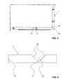
- the grooves 15 are milled into the flat profile element such that they, as shown in FIG. 6 can be seen, of two flat surfaces 16 and an intermediate, curved surface 17 are limited.
- the flat surfaces 16 enclose an angle of approximately 90 °.
- the flat profile element can then with little effort and in a precise manner in the in FIG. 3 shown, rectangular shape of the frame 1 are brought with well-defined corners 19.
- the flat surfaces 16 of the grooves 15 each extend parallel to each other, and substantially parallel to the bisector predetermined by the respective corner region 19 (see FIG. 5 ).
- connecting holes 12 are formed, which in particular allow the production of screw with the front panel 2, the rear wall 5 and the connection plate 3 explained below.
- the connecting bores 12 may each be provided with an internal thread.
- the connections can also be made by means of screw and nut.
- the compounds of the mentioned components can also be designed, for example, as adhesive or riveted joints.
- the flat profile element used for the production of the frame 1 has two ends in the longitudinal direction, which in the present embodiment after the formation of the frame 1 are arranged directly adjacent to each other or even abut each other to form a joint 13.
- This junction 13 is, as it is in the Figures 5 . 7 and 8 is shown connected by means of a connecting plate 3.
- This connection plate 3 is screwed to the outside of the frame 1 such that it is fixedly attached to both ends of the flat profile element.
- the connection plate 3 and the frame 1 in the region of the connection point 13 each have corresponding holes 31 and 12, respectively.
- the frame 1 has a recess 11. This is formed in the space provided for the preparation of the frame 1 flat profile element in the region of the two ends as a respective outwardly open recess. Due to the recess 11, the two ends of the flat profile element therefore each have a substantially U-shaped configuration. After joining the two ends of the flat profile element at the connection point 13, the recess 11 describes a rectangular shape, which is completely covered by the connection plate 3 downwards.
- the recess 11 serves to receive an electronic component, which in particular can be designed as a printed circuit board or printed circuit board.
- the recess 11 serves to receive a populated with LEDs and sensors printed circuit board.
- the LEDs and sensors are used to display the operating state of the flat screen recorded in the housing or to measure the brightness conditions in the environment.
- the frame 1 has viewing bores 10, which extend from an inner surface of the recess 11 to the forwardly directed surface of the frame 1, and which thus extend substantially parallel to the direction in which a viewer usually on the display surface a recorded in the housing screen looks.
- the sight holes 10 are each arranged such that they are aligned with mounted on the frame 1 front panel 2 with the recesses 23 of the front panel 2. A visual connection from the outside to the LEDs or sensors of the printed circuit board is thus ensured by the sight bores 10 and the recesses 23 therethrough.
- two opposite notches 14 are present at the edge of the recess 11.
- the notches 14 are adapted to receive correspondingly shaped pins which are attached to the printed circuit board and project laterally from this.
- the notches 14 are each formed to the recess 11 and the underside of the frame 1 towards open.
- a printed circuit board can be used in a simple manner from below into the recess 11 and with the laterally projecting pins in the notches 14.
- the connecting plate 3 is attached to the frame 1, the notches 14 are closed at the bottom, so that the printed circuit board is held with their laterally projecting pins in the notches 14.
- a circumferential inner groove 18 is formed on the inside of the frame 1.
- This inner groove 18 is disposed in a front portion of the frame 1.
- the inner groove 18 is already milled into the not yet formed into a frame 1 flat profile element.
- the inner groove 18 then extends parallel to the longitudinal direction of the flat profile element and preferably substantially over the entire length of the flat profile element.
- the inner groove 18 but also after bending of the flat profile element to a frame. 1 are milled in the inside.
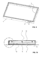
- the inner groove 18 is used for insertion of heat-dissipating strips 7, which in the Figures 9 and 11 are clearly recognizable.
- a heat dissipating bar 7 is inserted into the inner groove 18, in particular pressed.
- the heat-dissipating strips 7 are made of a good heat-conducting material, in particular a metal sheet.
- the housing is designed such that a flat screen recorded in the housing rests with its forwardly directed edge region directly substantially circumferentially on the respective rearwardly directed side of the heat-dissipating strips 7. In this way, heat, which arises in particular due to the backlighting in the flat screen, be transmitted by means of heat conduction via the heat dissipating strips 7 on the frame 1.
- the rear wall 5 which may be made in particular of a simple aluminum sheet, has vertically protruding connecting straps 51, which are arranged substantially circumferentially around the rear wall 5 around (see FIGS. 10 to 12 ).
- the connecting straps 51 on the one hand serve for fastening the rear wall 5 on the inside of the frame 1 by means of screw connections.
- the connecting straps 51 also serve to produce a thermally conductive connection between the frame 1 and the rear wall 5. Thermal energy arising in the flat screen, which is transmitted from the edge strips 7 to the frame 1, can thereby be conducted on the rear wall 5 via the connecting straps 51 become.
- heat radiating elements such as rib-like structures, may be attached, which radiate the heat energy into the environment. In the present embodiment, however, no such heat radiating elements are provided, since the rear wall 5 already forms a sufficiently large area in order to radiate the heat energy arising in the flat screen outwards.
- the rear wall 5 is preferably screwed to the frame 1 in such a way that a flat screen accommodated in the interior of the housing is held firmly between the heat-dissipating strips 7 and the rear wall 5 and, in particular, is clamped therebetween. A optimal heat transfer from the flat screen to the housing can be ensured.
- screw-nut connections are provided for the connections between the connecting plates 51 and the frame 1, and also the corresponding connection holes 12 are formed such that the screw before tightening the respective screw a certain play in the connecting hole 12, a tight concerns of the rear wall 5 are ensured at the rear of the flat screen even with manufacturing tolerances.
- the windshield 4 is preferably placed on the forwardly facing surfaces of the heat-dissipating strips 7 and in particular adhered thereto.
- FIGS. 10 to 12 an alternative, less preferred embodiment is shown with respect to the arrangement of the windshield 4, in which the windshield 4 is adhered to the rearwardly facing surfaces of the heat dissipating strips 7 instead of to the forwardly facing surfaces.
- the windscreen 4 is thus arranged between the heat-dissipating strips 7 and the flat screen in this alternative embodiment.
- an arrangement in which the heat dissipating strips 7, unlike in the figures, between the windscreen 4 and the flat screen are preferred.
- the invention described herein is not limited to the mentioned embodiment, and a variety of modifications are possible.
- the production of the frame 1 from a flat profile element with a plurality of predetermined bending points on the one hand, and the provision of an inner groove 18 on the frame 1 for insertion of the heat-dissipating elements 7 on the other hand represent two independent inventions.
- a housing with a frame to provide which is made of a flat profile element with a plurality of predetermined bending points, but has no inner groove for heat-dissipating elements. The heat can then be dissipated in another manner known to those skilled in the art.
- a housing with a frame which has on its inner side an inner groove for heat dissipating elements, but is not made of a flat profile element, but for example made of cast aluminum. If heat-dissipating strips are present, they do not necessarily have to be provided peripherally.
- a housing with a frame is conceivable, which, for example, only along its upper side has a heat dissipating bar.
- the heat-dissipating elements do not even have to be designed as strips, but can be configured as any protrusions projecting from the inside of the frame into the housing interior 8, which projections are suitable for contact with the flat-screen.
- the frame does not necessarily have to be designed in such a way that it is completely closed in the circumferential direction.
- the two ends of the flat profile element can also be arranged at a distance from each other in the finished bent frame, and it is not absolutely necessary that they are connected to one another via a connecting plate.
- the front panel 2, the frame 1, the connecting plate 3, the heat-dissipating strips 7, the rear wall 5 and the control circuit module 6 may be interconnected in any manner known to those skilled in the art.
- screw, rivet or adhesive connections are conceivable.
- the predetermined bending points need not necessarily be formed as milled grooves, but can be formed by any material dilutions at the appropriate points, for example, by means of rollers, press, etc., be formed. Also, predetermined bending points based on perforations at the corresponding points of the flat profile element are possible.
- 5 further heat dissipating elements may be attached to the inner surface of the rear wall, which are provided for abutment with the rear wall of the flat panel.
- These heat-dissipating elements can in particular be designed in such a way that, due to their shape, they are at least slightly elastically compressible in a direction perpendicular to the inner surface of the rear wall. The heat-dissipating elements are then clamped like a spring between the two surfaces of the rear wall and the flat screen.
- Such a shape of these additional heat-dissipating elements can be achieved, for example, by having an overall Z-shaped or S-shaped configuration. The compressibility ensures that these heat-dissipating elements, even taking into account manufacturing tolerances at any time abut the flat screen recorded in the housing and thereby derive the resulting heat to the rear wall and thus to the outside.
Landscapes
- Engineering & Computer Science (AREA)
- Theoretical Computer Science (AREA)
- Physics & Mathematics (AREA)
- General Engineering & Computer Science (AREA)
- Microelectronics & Electronic Packaging (AREA)
- Human Computer Interaction (AREA)
- General Physics & Mathematics (AREA)
- Thermal Sciences (AREA)
- Computer Hardware Design (AREA)
- Devices For Indicating Variable Information By Combining Individual Elements (AREA)
Priority Applications (4)
| Application Number | Priority Date | Filing Date | Title |
|---|---|---|---|
| EP12181373.7A EP2701475A1 (fr) | 2012-08-22 | 2012-08-22 | Boîtier destiné à la réception d'un écran plat |
| CA2823169A CA2823169A1 (fr) | 2012-08-22 | 2013-08-01 | Boitier pour ecran plat |
| CN201310367442.5A CN103635041A (zh) | 2012-08-22 | 2013-08-21 | 用于保持平面屏幕的壳体 |
| US13/973,201 US20140055011A1 (en) | 2012-08-22 | 2013-08-22 | Housing for Holding a Flat Screen |
Applications Claiming Priority (1)
| Application Number | Priority Date | Filing Date | Title |
|---|---|---|---|
| EP12181373.7A EP2701475A1 (fr) | 2012-08-22 | 2012-08-22 | Boîtier destiné à la réception d'un écran plat |
Publications (1)
| Publication Number | Publication Date |
|---|---|
| EP2701475A1 true EP2701475A1 (fr) | 2014-02-26 |
Family
ID=46717790
Family Applications (1)
| Application Number | Title | Priority Date | Filing Date |
|---|---|---|---|
| EP12181373.7A Withdrawn EP2701475A1 (fr) | 2012-08-22 | 2012-08-22 | Boîtier destiné à la réception d'un écran plat |
Country Status (4)
| Country | Link |
|---|---|
| US (1) | US20140055011A1 (fr) |
| EP (1) | EP2701475A1 (fr) |
| CN (1) | CN103635041A (fr) |
| CA (1) | CA2823169A1 (fr) |
Cited By (1)
| Publication number | Priority date | Publication date | Assignee | Title |
|---|---|---|---|---|
| AT16327U1 (de) * | 2017-10-30 | 2019-07-15 | PAG Solutions GmbH | Monitor |
Families Citing this family (4)
| Publication number | Priority date | Publication date | Assignee | Title |
|---|---|---|---|---|
| US20140029170A1 (en) * | 2012-07-24 | 2014-01-30 | Shenzhen China Star Optoelectronics Technology Co. Ltd. | Front Frame, Method for Making The Same, and Liquid Crystal Display Device |
| DE102018119539A1 (de) * | 2018-08-10 | 2020-02-13 | ambigence GmbH & Co. KG | Wand für ein Möbel, Verfahren zur Herstellung einer solchen Wand und Möbelkorpus oder Möbel mit einer solchen Wand |
| CN112469248A (zh) * | 2020-11-27 | 2021-03-09 | 江苏高明安光电有限公司 | 一种条形显示屏的散热结构 |
| CN112965280B (zh) * | 2021-02-05 | 2022-10-14 | 海信视像科技股份有限公司 | 显示装置 |
Citations (7)
| Publication number | Priority date | Publication date | Assignee | Title |
|---|---|---|---|---|
| US20050168954A1 (en) * | 2004-01-07 | 2005-08-04 | Yong-Il Kim | Chassis and display device having the same |
| US20060227077A1 (en) * | 2005-04-07 | 2006-10-12 | Lim Ji H | Display apparatus with cooling means |
| US7259964B2 (en) | 2004-10-04 | 2007-08-21 | Sony Corporation | Display device |
| US20080174945A1 (en) * | 2007-01-19 | 2008-07-24 | Jeoung-Gwen Lee | Display device and case for the same |
| US7619881B1 (en) | 2007-01-11 | 2009-11-17 | Lockheed Martin Corporation | Display component modules |
| US7876553B2 (en) | 2005-12-19 | 2011-01-25 | Hitachi, Ltd. | Flat-panel display apparatus |
| US20120075802A1 (en) | 2010-09-24 | 2012-03-29 | Pace Plc | Means for heat dissipation for electrical and/or electronic apparatus |
Family Cites Families (17)
| Publication number | Priority date | Publication date | Assignee | Title |
|---|---|---|---|---|
| JP4421963B2 (ja) * | 2004-07-15 | 2010-02-24 | Necインフロンティア株式会社 | 電子機器 |
| KR100598406B1 (ko) * | 2004-11-17 | 2006-07-07 | 삼성전자주식회사 | 디스플레이장치 |
| KR100717784B1 (ko) * | 2005-02-24 | 2007-05-11 | 삼성에스디아이 주식회사 | 플라즈마 디스플레이 장치 |
| KR100747820B1 (ko) * | 2005-11-04 | 2007-08-08 | 엘지전자 주식회사 | 평면 디스플레이 기기의 냉각 장치 |
| KR100768229B1 (ko) * | 2006-05-02 | 2007-10-18 | 삼성에스디아이 주식회사 | 플라즈마 표시장치 |
| KR101315465B1 (ko) * | 2006-10-16 | 2013-10-04 | 삼성전자주식회사 | 냉각 팬 유닛 및 이를 갖는 디스플레이장치 |
| KR101273592B1 (ko) * | 2007-01-08 | 2013-06-11 | 삼성전자주식회사 | 패널형 디스플레이장치 |
| JP4273357B2 (ja) * | 2007-03-06 | 2009-06-03 | 船井電機株式会社 | 薄型表示装置の冷却ファン取付構造、及びプラズマテレビ |
| KR101456975B1 (ko) * | 2007-09-27 | 2014-10-31 | 삼성전자 주식회사 | 냉각유닛 및 이를 갖는 디스플레이장치 |
| KR101407622B1 (ko) * | 2007-11-09 | 2014-06-13 | 삼성디스플레이 주식회사 | 표시 장치 |
| US20090231808A1 (en) * | 2008-03-11 | 2009-09-17 | Robert Daniel Burgner | Enclosure For Flat Panel Monitors |
| CN102077262A (zh) * | 2008-07-15 | 2011-05-25 | 夏普株式会社 | 加固框架、部件单元和显示装置 |
| JP2010054718A (ja) * | 2008-08-27 | 2010-03-11 | Sony Corp | 表示装置 |
| JP2010081280A (ja) * | 2008-09-26 | 2010-04-08 | Hitachi Ltd | 映像表示装置 |
| JP2011049367A (ja) * | 2009-08-27 | 2011-03-10 | Panasonic Corp | 基板接続構造および電子機器 |
| CN102033576A (zh) * | 2009-09-28 | 2011-04-27 | 鸿富锦精密工业(深圳)有限公司 | 笔记本计算机 |
| JP2012242445A (ja) * | 2011-05-16 | 2012-12-10 | Sony Corp | 表示装置 |
-
2012
- 2012-08-22 EP EP12181373.7A patent/EP2701475A1/fr not_active Withdrawn
-
2013
- 2013-08-01 CA CA2823169A patent/CA2823169A1/fr active Pending
- 2013-08-21 CN CN201310367442.5A patent/CN103635041A/zh active Pending
- 2013-08-22 US US13/973,201 patent/US20140055011A1/en not_active Abandoned
Patent Citations (7)
| Publication number | Priority date | Publication date | Assignee | Title |
|---|---|---|---|---|
| US20050168954A1 (en) * | 2004-01-07 | 2005-08-04 | Yong-Il Kim | Chassis and display device having the same |
| US7259964B2 (en) | 2004-10-04 | 2007-08-21 | Sony Corporation | Display device |
| US20060227077A1 (en) * | 2005-04-07 | 2006-10-12 | Lim Ji H | Display apparatus with cooling means |
| US7876553B2 (en) | 2005-12-19 | 2011-01-25 | Hitachi, Ltd. | Flat-panel display apparatus |
| US7619881B1 (en) | 2007-01-11 | 2009-11-17 | Lockheed Martin Corporation | Display component modules |
| US20080174945A1 (en) * | 2007-01-19 | 2008-07-24 | Jeoung-Gwen Lee | Display device and case for the same |
| US20120075802A1 (en) | 2010-09-24 | 2012-03-29 | Pace Plc | Means for heat dissipation for electrical and/or electronic apparatus |
Cited By (1)
| Publication number | Priority date | Publication date | Assignee | Title |
|---|---|---|---|---|
| AT16327U1 (de) * | 2017-10-30 | 2019-07-15 | PAG Solutions GmbH | Monitor |
Also Published As
| Publication number | Publication date |
|---|---|
| CA2823169A1 (fr) | 2014-02-22 |
| CN103635041A (zh) | 2014-03-12 |
| US20140055011A1 (en) | 2014-02-27 |
Similar Documents
| Publication | Publication Date | Title |
|---|---|---|
| EP0927510B1 (fr) | Boitier dissipateur de chaleur servant a loger des composants electriques ou electroniques | |
| EP2701475A1 (fr) | Boîtier destiné à la réception d'un écran plat | |
| EP2592525B1 (fr) | Moniteur ainsi que couvercle pour un moniteur | |
| DE202014102461U1 (de) | Gekrümmte Anzeigevorrichtung | |
| DE102011120202A1 (de) | Elektrische Steuereinheit | |
| EP1841302B1 (fr) | Appareil de commande électronique dans des véhicules | |
| DE102006034777A1 (de) | Kombination aus einem Wechselrichtergehäuses und einem als Wärme-Senke fungierenden Bauteil | |
| DE112013007413T5 (de) | Elektronische Vorrichtung | |
| EP2550556B1 (fr) | Dispositif d'affichage et montage dudit dispositif d'affichage | |
| DE112018002422T5 (de) | Schaltungsanordnung und elektrischer Verteilerkasten | |
| DE102006010064A1 (de) | Aufnahme für Befestigungselement | |
| DE112014001321T5 (de) | Elektronikkomponenten-Anordnungsaufbau und elektrischer Anschlusskasten | |
| EP2835042B1 (fr) | Boîtier extensible pour composants électriques, intercalaire pour le boîtier extensible, et procédé de fabrication et de montage du boîtier | |
| EP2699066A1 (fr) | Élément de verrouillage destiné à verrouiller une coiffe sur un rail de module | |
| DE60309786T2 (de) | Anzeigevorrichtung mit Anzeigetafel | |
| DE102013001830B4 (de) | Elektrizitätszähler mit einem Fach zur Aufnahme eines Schilds | |
| EP1630643B1 (fr) | Boîtier à double paroi pour panneaux industriels et panel PCs | |
| EP2237998B1 (fr) | Carter d'engrenage d'un système essuie-glace avec un point d'emboîtement comme point de fixation | |
| DE102013015352B4 (de) | Blendenprofil zur Anbringung einer Abschlussblende an einem Ojekt, zum Beispiel einem Möbelstück und System, umfassend ein Blendenprofil, ein Objekt und eine Abschlussblende | |
| DE102009007612B4 (de) | Kühlkörper zur Abfuhr von Wärme von elektronischen Bauteilen und Verfahren zu seiner Herstellung | |
| DE202011052516U1 (de) | Befestigungseinrichtung für ein Flächenelement in einem unterhaltungselektronischen Gerät | |
| DE102004028702B4 (de) | Schaltungsmodul und Verfahren zu dessen Herstellung | |
| EP3521969B1 (fr) | Boîtier à partir des parties de boîtier raccordées de manière amovible | |
| DE102006052304B4 (de) | Rahmen für elektrische und elektronische Geräte, insbesondere Frontrahmen für Anzeigegeräte | |
| EP1811826B1 (fr) | Boîtier d'un dispositif électronique d'un véhicule |
Legal Events
| Date | Code | Title | Description |
|---|---|---|---|
| PUAI | Public reference made under article 153(3) epc to a published international application that has entered the european phase |
Free format text: ORIGINAL CODE: 0009012 |
|
| AK | Designated contracting states |
Kind code of ref document: A1 Designated state(s): AL AT BE BG CH CY CZ DE DK EE ES FI FR GB GR HR HU IE IS IT LI LT LU LV MC MK MT NL NO PL PT RO RS SE SI SK SM TR |
|
| AX | Request for extension of the european patent |
Extension state: BA ME |
|
| 17P | Request for examination filed |
Effective date: 20140711 |
|
| RBV | Designated contracting states (corrected) |
Designated state(s): AL AT BE BG CH CY CZ DE DK EE ES FI FR GB GR HR HU IE IS IT LI LT LU LV MC MK MT NL NO PL PT RO RS SE SI SK SM TR |
|
| 17Q | First examination report despatched |
Effective date: 20161020 |
|
| STAA | Information on the status of an ep patent application or granted ep patent |
Free format text: STATUS: THE APPLICATION IS DEEMED TO BE WITHDRAWN |
|
| 18D | Application deemed to be withdrawn |
Effective date: 20180301 |