EP2700616A2 - Zweiteiliger Ventilkörper für ein Wasserbehandlungssystem - Google Patents
Zweiteiliger Ventilkörper für ein Wasserbehandlungssystem Download PDFInfo
- Publication number
- EP2700616A2 EP2700616A2 EP13162460.3A EP13162460A EP2700616A2 EP 2700616 A2 EP2700616 A2 EP 2700616A2 EP 13162460 A EP13162460 A EP 13162460A EP 2700616 A2 EP2700616 A2 EP 2700616A2
- Authority
- EP
- European Patent Office
- Prior art keywords
- valve body
- exterior
- side wall
- exterior side
- wall
- Prior art date
- Legal status (The legal status is an assumption and is not a legal conclusion. Google has not performed a legal analysis and makes no representation as to the accuracy of the status listed.)
- Withdrawn
Links
Images

Classifications
-
- C—CHEMISTRY; METALLURGY
- C02—TREATMENT OF WATER, WASTE WATER, SEWAGE, OR SLUDGE
- C02F—TREATMENT OF WATER, WASTE WATER, SEWAGE, OR SLUDGE
- C02F1/00—Treatment of water, waste water, or sewage
- C02F1/42—Treatment of water, waste water, or sewage by ion-exchange
-
- C—CHEMISTRY; METALLURGY
- C02—TREATMENT OF WATER, WASTE WATER, SEWAGE, OR SLUDGE
- C02F—TREATMENT OF WATER, WASTE WATER, SEWAGE, OR SLUDGE
- C02F1/00—Treatment of water, waste water, or sewage
- C02F1/006—Water distributors either inside a treatment tank or directing the water to several treatment tanks; Water treatment plants incorporating these distributors, with or without chemical or biological tanks
-
- C—CHEMISTRY; METALLURGY
- C02—TREATMENT OF WATER, WASTE WATER, SEWAGE, OR SLUDGE
- C02F—TREATMENT OF WATER, WASTE WATER, SEWAGE, OR SLUDGE
- C02F1/00—Treatment of water, waste water, or sewage
- C02F1/008—Control or steering systems not provided for elsewhere in subclass C02F
-
- C—CHEMISTRY; METALLURGY
- C02—TREATMENT OF WATER, WASTE WATER, SEWAGE, OR SLUDGE
- C02F—TREATMENT OF WATER, WASTE WATER, SEWAGE, OR SLUDGE
- C02F2201/00—Apparatus for treatment of water, waste water or sewage
- C02F2201/002—Construction details of the apparatus
- C02F2201/005—Valves
-
- Y—GENERAL TAGGING OF NEW TECHNOLOGICAL DEVELOPMENTS; GENERAL TAGGING OF CROSS-SECTIONAL TECHNOLOGIES SPANNING OVER SEVERAL SECTIONS OF THE IPC; TECHNICAL SUBJECTS COVERED BY FORMER USPC CROSS-REFERENCE ART COLLECTIONS [XRACs] AND DIGESTS
- Y10—TECHNICAL SUBJECTS COVERED BY FORMER USPC
- Y10T—TECHNICAL SUBJECTS COVERED BY FORMER US CLASSIFICATION
- Y10T137/00—Fluid handling
- Y10T137/598—With repair, tapping, assembly, or disassembly means
- Y10T137/6089—With mechanical movement between actuator and valve
- Y10T137/6103—Cam type
-
- Y—GENERAL TAGGING OF NEW TECHNOLOGICAL DEVELOPMENTS; GENERAL TAGGING OF CROSS-SECTIONAL TECHNOLOGIES SPANNING OVER SEVERAL SECTIONS OF THE IPC; TECHNICAL SUBJECTS COVERED BY FORMER USPC CROSS-REFERENCE ART COLLECTIONS [XRACs] AND DIGESTS
- Y10—TECHNICAL SUBJECTS COVERED BY FORMER USPC
- Y10T—TECHNICAL SUBJECTS COVERED BY FORMER US CLASSIFICATION
- Y10T137/00—Fluid handling
- Y10T137/8593—Systems
- Y10T137/87249—Multiple inlet with multiple outlet
-
- Y—GENERAL TAGGING OF NEW TECHNOLOGICAL DEVELOPMENTS; GENERAL TAGGING OF CROSS-SECTIONAL TECHNOLOGIES SPANNING OVER SEVERAL SECTIONS OF THE IPC; TECHNICAL SUBJECTS COVERED BY FORMER USPC CROSS-REFERENCE ART COLLECTIONS [XRACs] AND DIGESTS
- Y10—TECHNICAL SUBJECTS COVERED BY FORMER USPC
- Y10T—TECHNICAL SUBJECTS COVERED BY FORMER US CLASSIFICATION
- Y10T137/00—Fluid handling
- Y10T137/8593—Systems
- Y10T137/87265—Dividing into parallel flow paths with recombining
- Y10T137/87338—Flow passage with bypass
- Y10T137/87362—Including cleaning, treating, or heat transfer feature
- Y10T137/8737—Water treatment feature
Definitions
- the present invention relates to apparatus for treating water, such as water softeners; and more particularly to a valve assembly for controlling the regeneration of the treatment medium in such apparatus.
- the most common kind of water softener is an ion exchange apparatus that has a tank containing a resin bed through which the hard water flows to remove undesirable minerals and other impurities. Binding sites in the resin bed initially contain positive ions, commonly unipositive sodium or potassium ions. As hard water enters the bed, competition for the binding sites occurs. The di-positive and tri-positive ions in the hard water are favored due to their higher charge densities and displace the unipositive ions. Two or three unipositive ions are displaced for each di-positive or tri-positive ion, respectively.
- the capacity of the resin bed to absorb minerals and impurities is finite and eventually ceases to soften the water when a large percentage of the sites become occupied by the di-positive and tri-positive ions.
- a regenerant typically a solution of sodium chloride or potassium chloride.
- the concentration of unipositive ions in the regenerant is sufficiently high to offset the unfavorable electrostatic competition and the binding sites are recovered by unipositive ions.
- the interval of time between regeneration periods during which water softening takes place is referred to as a service mode of operation.
- Regeneration of water softeners is controlled by a valve arrangement that is automatically operated a motor through the standard regeneration cycle to flush, regenerate, and rinse the resin bed.
- a controller activates the motor based on the length of time since the previous regeneration, the amount of water that was treated, or the conductivity of the resin bed which indicates the remaining treatment capacity.
- the valve arrangement is housed in a body with external connections for a water inlet, a water outlet, a regenerate reservoir, and a drain line.
- the body also includes a fitting to which the resin tank attaches.
- the external connections and the fitting communicate with a plurality of passages in the body that are selectively connected to one another by the operation of the valve arrangement.
- the valve body consisted of many different sections that were molded or machined separately before being fastened together to form the complete body.
- An example of one type of a prior valve assembly is described in U.S. Patent No. 5,910,244 .
- the complexity of the external connections and internal passages made reducing the number of valve body sections difficult without adding to the machining steps and thus the cost of the body.
- valve body in a way that reduces the number of parts, while facilitating casting the parts in a manner that eliminates subsequent machining.
- a valve body for a water treatment apparatus, is substantially formed by only a first part and a second part sealingly joined together to define a plurality of internal fluid chambers.
- the valve body has a primary exterior wall and a secondary exterior wall with a first, second, third and fourth exterior side walls extending between the primary and secondary exterior walls.
- the valve body further comprises a plurality of openings for an inlet valve element, an outlet valve element, a rinse valve element, a backwash valve element and a regenerant valve element that control flow of fluid through the valve body.
- the valve body also has a fluid fitting for connection to a water treatment vessel.
- the first and second parts are joined at a seam that extends at an acute angle, and preferably diagonally, through the first and second exterior side walls.
- the first part comprises the secondary exterior wall and a section of each of the first and second exterior side walls, and further includes an untreated water inlet, a treated water outlet, a drain outlet, and a regenerant inlet.
- the second part comprises the primary exterior wall and another section of each of the first and second exterior side walls.
- the configuration of the first and second parts enables the entire valve body, with all the necessary connections and openings for actuating valve elements, to be formed by only two parts which can be fabricated by conventional injection molding techniques.
- a water softener 10 includes a treatment tank, or vessel 12, which contains a bed 14 of ion exchange resin particles.
- hard water to be softened supplied to an inlet coupling 20, flows through the valve body 18 to vessel inlets 22 in a fitting 25 at the top of the treatment vessel 12. That water passes through the resin bed 14 that removes minerals from the water.
- Water that has been treated in the resin bed 14 flows into a riser conduit 24 that extends through the bed from a point adjacent the bottom of the treatment vessel 12 to a vessel outlet 26 in the valve body 18. From the vessel outlet 26, the water continues through the valve body 18 from it exits the water softener 10 at a water outlet 28 connected to pipes in a building.
- the resin bed 14 eventually becomes exhausted and no longer is capable of softening the water.
- the control valve assembly 16 initiates a standard regeneration process, as described in the aforementioned U.S. patent. That process commences with a backwash step in which hard water is directed through the valve body 18 into the vessel outlet 26 and upwards through the resin bed 14 finally exiting the water softener via a drain coupling 30.
- the backwash step is followed by a brining step in which the controller draws a regenerant, commonly called “brine”, through a regenerant connector 32 that is connected by a tube 34 to a brine tank 36.
- the brine tank 36 contains a regenerant solution 38 of a common salt, such as a sodium chloride or potassium chloride.
- a partial vacuum created by the flow of hard water through valve body 18, draws the regenerant solution from the brine tank 36 and into the treatment vessel 12.
- the concentrated regenerant solution replaces the di-positive and tri-positive ions in the resin bed 14 with unipositive ions thereby recharging the bed.
- the brine tank 36 is refilled with water to replenish the regenerant solution for the next regeneration process.
- the resin bed 14 is rinsed by passing water through the vessel 12 and out the drain coupling 30. Thereafter, the control valve assembly 16 returns the internal valve arrangement to a state that places the water softener 10 into the previously described service mode in which the water for the building is treated.
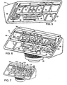
- FIG. 2 illustrates the control valve assembly 16 with the control panel 19 removed to show the front of the valve body 18 and valve actuating components attached thereto.
- the valve body 18 has a primary exterior wall 40, a secondary exterior wall 41, a first exterior side wall 44, a second exterior side wall 45, a third exterior side wall 42 at the top of the body, and a fourth exterior side wall 43 at the bottom of the body.
- a cam shaft 46 that is driven by an electric motor 47 is mounted to the primary exterior wall 40 and has a plurality of cams 48 thereon. As the cam shaft rotates, each cam operates a different flapper valve element within the valve body 18.
- cam 48 engages the stem 49 of flapper valve element 114. That action pivots the flapper valve element 114 to open and close an aperture 100, thereby controlling fluid flow between chambers 84 and 76 within the valve body 18.
- the secondary exterior wall 41 of the valve body 18 has a plurality of connectors through which fluid enters or exits the valve body.
- An untreated water inlet 62 is adapted to be connected to the supply pipe of the plumbing system for the building in which the water softener 10 is located and receives water for treatment by the water softener. After such treatment, water exits a treated water outlet 64 and returns to the building plumbing system. During regeneration, waste water exits the valve body 18 through a drain outlet 66 and flows to the waste water system of the building.
- the regenerant connector 32 also is located on the secondary exterior wall 41 of the valve body 18. As shown in Figures 2-4 , the fitting 25 for connection to the treatment vessel 12 projects from the fourth exterior side wall 43 of the valve body 18 and has a threaded outer surface that engages threads on the opening of the treatment vessel.
- the valve body 18 is divided into a single piece first part 70 and a single piece second part 71 along a seam 68 that substantially diagonally bisects the first and second exterior side walls 44 and 45 so that a section of each exterior side wall is included on each part.
- the portions of the seam 68 in the first and second exterior side walls 44 and 45 extend at acute angles ( ⁇ and ⁇ ) with respect to the third and fourth exterior side walls.
- the seam 68 extends across the front of the valve body proximate to a junction between the primary exterior wall 40 and the third exterior side wall 42.
- substantially the entire third exterior side wall 42 is included in the second part 71, with the exception of a flange 39 around the cam shaft 46 and motor 47.
- the seam 68 further extends across the back of the valve body 18 proximate to a junction between the secondary exterior wall 41 and the fourth exterior side wall 43, so that the substantially the entire fourth exterior side wall is included in the first part 70.
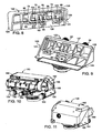
- This division of the body produces first and second parts 70 and 71 that are generally a wedge-shaped pentahedron with triangular sides between which extend two perpendicular sides and one oblique open side 67 or 69, as shown in Figures 5 and 6 .
- the first and second parts 70 and 71 of the valve body 18 are fitted together so that their respective oblique open sides 67 and 69 abut each other forming the seam 68. Those surfaces are either welded or cemented together to seal the interior walls of the body 18 thereby enclosing a plurality of internal chambers to be described.
- substantially the entire third exterior side wall is included in one part 70 or 71, and substantially the entire fourth exterior side wall is included in one part 71 or 70 allows for one or two relatively narrow strips of each such wall to be included in the other part, as long as such inclusion does not interfere with molding the internal walls and chambers of those parts.
- the portion of the flange 39 that forms a section of the third exterior side wall 42 does not inhibit a mold component from exiting the open side 69 of the molded first part 70.
- the seam 68 does not have to precisely bisect the first and second exterior side walls 44 and 45 of the valve body 18.
- the interior of the second part 71 of the valve body 18 is shown in Figure 5 , and the untreated water inlet 62 opens into an inlet chamber 72 and the treated water outlet 64 opens into an outlet chamber 74.
- the inlet chamber 72 continuously opens through a first aperture 73 into a bridge passage 75 that opens through a second aperture 77 into a bypass chamber 78.
- the bypass chamber 78 is adjacent a branch passage 79 from the outlet chamber 74 separated therefrom by an interior wall 80 which extends almost the full width of the valve body 18.
- the inlet chamber 72, bypass chamber 78 and outlet chamber 74 are located on a first side of the interior wall 80.
- the outlet chamber branch passage 79 extends through the interior wall 80 to a second side to a location opposite the bypass chamber 78.
- a rinse chamber 82 and a backwash chamber 84 are located along side each other on the first side of the interior wall 80 between the inlet and bypass chambers 72 and 78.
- the drain outlet 66 communicates with a drain chamber 76 on the second side of the interior wall 80 and opposite both the rinse and backwash chambers 82 and 84.
- the regenerant connector 32 opens into a regenerant chamber 86 that also is on the second side of the interior wall 80.
- a regenerant valve chamber 88 is on the first side of the interior wall 80 opposite to the regenerant chamber 86 and has a branch passage 89 that extends through the interior wall and opens into a vessel inlet chamber 90.
- the vessel inlet chamber 90 leads to the vessel inlets 22 in the fitting 25 for the treatment vessel 12 (see also Figures 1 and 6 ).
- the vessel outlet 26 projects upward through the interior of the fitting 25 and opens into a vessel outlet chamber 92 in the valve body.
- the first part 70 of the valve body 18, contains the primary exterior wall 40 with a plurality of valve openings for receiving the valve elements.
- the inlet chamber 72 has first valve opening 94 in the primary exterior wall 40 of the valve body into the inlet chamber 72 and receives an inlet flapper valve element 111.
- the inlet flapper valve element 111 selectively opens and closes a first valve aperture 93 through the interior wall 80 from the inlet chamber 72 to the vessel inlet chamber 90.
- the outlet chamber 74 has a second aperture 95 extending through the interior wall 80 into the vessel outlet chamber 92 and has a second opening 96 in the primary exterior wall 40 for receiving an outlet flapper valve element 112 that controls water flow through the second aperture.
- a third primary exterior wall opening 98 communicates with the rinse chamber 82 and holds the rinse flapper valve element 114 that selectively opens and closes a third aperture 97 leading into the drain chamber 76.
- the backwash chamber 84 has a fourth aperture 99 that also leads into the drain chamber 76 and the flow through which is controlled by a backwash flapper valve element 115 located in a fourth opening 101 in the primary exterior wall 40.
- the regenerant valve chamber 88 has an fifth aperture 100 through the interior wall 80 into the regenerant chamber 86.
- the fifth aperture 100 is opened and closed by a regenerant flapper valve element 113 held in a fifth opening 103 in the primary exterior wall.
- the he bypass chamber 78 has sixth aperture 102 through the interior wall 80 into the branch passage 79 from the outlet chamber 74.
- a sixth opening 104 through the primary exterior wall is provided for a bypass flapper valve element 113 the extends over the sixth aperture 102.
- Each of these flapper valve elements 111-116 is controlled by a different cam 48 of the cam shaft 46 on the front of the valve body shown in Figure 2 .
- Each of the first and second parts 70 and 71 is formed from a single piece of material and the two parts joined together substantially entirely form the plurality of internal fluid chambers described above.
- substantially entirely form means that the first and second parts contain all the walls of the internal fluid chambers, apertures between chambers, and exterior openings for components such as plumbing connections, valve elements, and venturi nozzles, for example.
- the first and second parts 70 and 71 may have one or more apertures that are closed by a plug.
- valve body 18 By dividing the valve body 18 into two pieces along a diagonal seam 68, portions of each chamber are defined by each part 70 and 71 and those parts can be fabricated by conventional injection molding techniques.
- the diagonal division allows two mold sections to come together along two orthogonal axes to form the different chambers and apertures in the valve body.
- An additional mold section moves perpendicular to the fourth exterior side wall 43 to form the vessel fitting 25 and the passages there through.
- the valve body 18 is able to be formed by only two pieces which entirely define the valve apertures, chambers and fluid passageways.
- the valve body 18 preferably consists of only two parts 70 and 71, other minor components, such as plugs for exterior or interior openings may be included, therefore the valve body 18 may consist essentially of only two parts.
- the valve body 18 is divided along a diagonal so that the first part 70 contains the primary exterior wall 40 and the treatment vessel fitting 25 while the second part 71 includes the secondary exterior wall 41 with the fluid connectors 62-66.
- the valve body 120 is divided by a seam 121 that extends in the opposite diagonal orientation through the first and second exterior side walls 124 and 125 to define the first and second parts 122 and 123. That seam 121 extends across the front of the valve body proximate to a junction between the primary exterior wall 126 and the fourth exterior side wall 129, and across the back of the valve body 120 proximate to a junction between the secondary exterior wall 127 and the third exterior side wall 128.
- substantially the entire third exterior side wall 128 is included in the first part 122 and substantially the entire fourth exterior side wall 129 is included in the second part 123.
- FIGS 10 and 11 illustrate a third embodiment of a valve body 150, according to the present invention.
- the secondary exterior wall 152 of that valve body 150 contains the plumbing connections for the untreated water inlet 153, the treated water outlet 154, the drain outlet 155, and the regenerant inlet 156.
- the cam shaft 158 for operating the flapper valve elements and its drive motor 160 are mounted on the secondary exterior wall 152. In this case, the stems of the flapper valves protrude through openings in that secondary exterior wall 152 behind the cam shaft 158.
- the valve body 150 is divided into a front, or first, part 162 and a rear, or second, part 164 along a seam 166, which extends diagonally through each of the first and second exterior side walls 168 and 169 from the upper rear edge to the lower front edge of the body.
Landscapes
- Life Sciences & Earth Sciences (AREA)
- Hydrology & Water Resources (AREA)
- Engineering & Computer Science (AREA)
- Environmental & Geological Engineering (AREA)
- Water Supply & Treatment (AREA)
- Chemical & Material Sciences (AREA)
- Organic Chemistry (AREA)
- Treatment Of Water By Ion Exchange (AREA)
Applications Claiming Priority (2)
| Application Number | Priority Date | Filing Date | Title |
|---|---|---|---|
| US11/349,758 US7610933B2 (en) | 2006-02-08 | 2006-02-08 | Two part valve body for a water treatment system |
| EP07716361A EP1986958A2 (de) | 2006-02-08 | 2007-01-05 | Zweiteiliger ventilkörper für ein wasserbehandlungssystem |
Related Parent Applications (2)
| Application Number | Title | Priority Date | Filing Date |
|---|---|---|---|
| EP07716361A Division EP1986958A2 (de) | 2006-02-08 | 2007-01-05 | Zweiteiliger ventilkörper für ein wasserbehandlungssystem |
| PCT/US2007/000279 Previously-Filed-Application WO2007092109A2 (en) | 2006-02-08 | 2007-01-05 | Two part valve body for a water treatment system |
Publications (2)
| Publication Number | Publication Date |
|---|---|
| EP2700616A2 true EP2700616A2 (de) | 2014-02-26 |
| EP2700616A3 EP2700616A3 (de) | 2014-11-05 |
Family
ID=38069191
Family Applications (2)
| Application Number | Title | Priority Date | Filing Date |
|---|---|---|---|
| EP20130162460 Withdrawn EP2700616A3 (de) | 2006-02-08 | 2007-01-05 | Zweiteiliger Ventilkörper für ein Wasserbehandlungssystem |
| EP07716361A Ceased EP1986958A2 (de) | 2006-02-08 | 2007-01-05 | Zweiteiliger ventilkörper für ein wasserbehandlungssystem |
Family Applications After (1)
| Application Number | Title | Priority Date | Filing Date |
|---|---|---|---|
| EP07716361A Ceased EP1986958A2 (de) | 2006-02-08 | 2007-01-05 | Zweiteiliger ventilkörper für ein wasserbehandlungssystem |
Country Status (6)
| Country | Link |
|---|---|
| US (1) | US7610933B2 (de) |
| EP (2) | EP2700616A3 (de) |
| JP (1) | JP4988769B2 (de) |
| KR (1) | KR20080094033A (de) |
| CN (1) | CN101378996B (de) |
| WO (1) | WO2007092109A2 (de) |
Families Citing this family (6)
| Publication number | Priority date | Publication date | Assignee | Title |
|---|---|---|---|---|
| US7568501B2 (en) * | 2006-02-08 | 2009-08-04 | Ge Osmonics, Inc. | Bypass valve with flapper valve elements for a water treatment apparatus |
| US9010361B2 (en) | 2011-10-27 | 2015-04-21 | Pentair Residential Filtration, Llc | Control valve assembly |
| WO2014049836A1 (ja) * | 2012-09-28 | 2014-04-03 | 三浦工業株式会社 | 流路制御弁 |
| KR200475329Y1 (ko) * | 2014-06-18 | 2014-11-24 | 이상화 | 금형의 작업유체 흐름 확인기구 |
| US10612670B2 (en) | 2015-10-23 | 2020-04-07 | Culligan International Company | Control valve for fluid treatment apparatus |
| EP3308858B1 (de) * | 2016-10-13 | 2019-12-25 | OAV Objekte und Anlagen Vermietung GmbH | Vorrichtung zum entsalzen von wasser |
Family Cites Families (11)
| Publication number | Priority date | Publication date | Assignee | Title |
|---|---|---|---|---|
| US2539221A (en) | 1944-08-26 | 1951-01-23 | James H Badeaux | Multiple control valve |
| US3475006A (en) * | 1967-06-06 | 1969-10-28 | Thetford Eng Corp | Ball valve |
| US3894719A (en) | 1971-11-08 | 1975-07-15 | Aqua Chem Inc | Water softener valve |
| US3797523A (en) * | 1972-09-11 | 1974-03-19 | D Brane | Low pressure drop water softener valve assembly with dual pistons |
| US3867961A (en) | 1973-11-16 | 1975-02-25 | Calgon Corp | Control valve for water conditioners |
| EP0882193A4 (de) | 1996-01-26 | 2000-12-06 | Autotrol Corp | Anpassbares regelventil für ein fluidumbehandlungssystem |
| JPH09297150A (ja) * | 1996-04-30 | 1997-11-18 | Miura Co Ltd | 位置検出装置及び水処理装置 |
| US6206042B1 (en) | 1998-03-06 | 2001-03-27 | Chemical Engineering Corporation | Modular control apparatus for water treatment system |
| JP4562251B2 (ja) * | 2000-07-13 | 2010-10-13 | 株式会社丸山製作所 | 硬水軟化装置 |
| JP2003065453A (ja) * | 2001-08-28 | 2003-03-05 | Smc Corp | バルブ用ボディ及びその製造方法 |
| ITVI20010266A1 (it) * | 2001-12-21 | 2003-06-21 | A T I Applic Tecnologich E Ad | Dispositivo addolcitore per acqua |
-
2006
- 2006-02-08 US US11/349,758 patent/US7610933B2/en not_active Expired - Fee Related
-
2007
- 2007-01-05 EP EP20130162460 patent/EP2700616A3/de not_active Withdrawn
- 2007-01-05 JP JP2008554235A patent/JP4988769B2/ja not_active Expired - Fee Related
- 2007-01-05 WO PCT/US2007/000279 patent/WO2007092109A2/en not_active Ceased
- 2007-01-05 KR KR1020087019418A patent/KR20080094033A/ko not_active Ceased
- 2007-01-05 CN CN2007800049938A patent/CN101378996B/zh not_active Expired - Fee Related
- 2007-01-05 EP EP07716361A patent/EP1986958A2/de not_active Ceased
Also Published As
| Publication number | Publication date |
|---|---|
| US7610933B2 (en) | 2009-11-03 |
| WO2007092109A3 (en) | 2007-10-11 |
| CN101378996A (zh) | 2009-03-04 |
| CN101378996B (zh) | 2012-04-18 |
| EP2700616A3 (de) | 2014-11-05 |
| WO2007092109A2 (en) | 2007-08-16 |
| KR20080094033A (ko) | 2008-10-22 |
| EP1986958A2 (de) | 2008-11-05 |
| US20070181193A1 (en) | 2007-08-09 |
| JP4988769B2 (ja) | 2012-08-01 |
| JP2009525864A (ja) | 2009-07-16 |
Similar Documents
| Publication | Publication Date | Title |
|---|---|---|
| WO2007106262A2 (en) | Water control valve | |
| US7610933B2 (en) | Two part valve body for a water treatment system | |
| WO2023240981A1 (zh) | 软水机 | |
| CN102884005B (zh) | 具有定时器控制阀的软水器 | |
| EP1844253B1 (de) | Kolben mit integrierten dichtungen für ein wasserenthärter-steuerungsventil | |
| CN114962713A (zh) | 多路阀及软水机 | |
| CN106510593A (zh) | 软水器和具有其的洗碗机 | |
| CN115072834A (zh) | 软水机 | |
| CN114941731A (zh) | 定阀片、阀体组件、多路阀及软水机 | |
| US20050235821A1 (en) | Water softener | |
| KR101595571B1 (ko) | 중력식 자동 재생 연수기 및 중력식 자동 재생 연수기의 자동 재생 방법 | |
| CN208851434U (zh) | 一种水软化器及洗碗机 | |
| KR102223012B1 (ko) | 연수기의 분리 가능한 재생통 및 재생통의 드레인 바스켓 | |
| CN101269862B (zh) | 洗衣机用软化器的再生装置 | |
| US7004200B1 (en) | Constant flow valve for a water softener control assembly | |
| KR100433999B1 (ko) | 연수기용 헤드 어셈블리 및 그를 이용한 연수기 | |
| CN114962714B (zh) | 多路阀及软水机 | |
| JPH08155447A (ja) | 軟水器 | |
| US20030084943A1 (en) | Motor operated control valve | |
| CN109691958A (zh) | 一种水软化器及洗碗机 | |
| KR200182046Y1 (ko) | 분리형 연수기 | |
| KR102592789B1 (ko) | 특정 탱크만 에어 제거를 수행하도록 형성된 연수기 | |
| KR200240007Y1 (ko) | 연수기 | |
| KR20050109094A (ko) | 연수기 | |
| JP2001087758A (ja) | 軟水供給装置 |
Legal Events
| Date | Code | Title | Description |
|---|---|---|---|
| PUAI | Public reference made under article 153(3) epc to a published international application that has entered the european phase |
Free format text: ORIGINAL CODE: 0009012 |
|
| AC | Divisional application: reference to earlier application |
Ref document number: 1986958 Country of ref document: EP Kind code of ref document: P |
|
| AK | Designated contracting states |
Kind code of ref document: A2 Designated state(s): AT BE BG CH CY CZ DE DK EE ES FI FR GB GR HU IE IS IT LI LT LU LV MC NL PL PT RO SE SI SK TR |
|
| PUAL | Search report despatched |
Free format text: ORIGINAL CODE: 0009013 |
|
| AK | Designated contracting states |
Kind code of ref document: A3 Designated state(s): AT BE BG CH CY CZ DE DK EE ES FI FR GB GR HU IE IS IT LI LT LU LV MC NL PL PT RO SE SI SK TR |
|
| RIC1 | Information provided on ipc code assigned before grant |
Ipc: C02F 1/42 20060101AFI20140929BHEP |
|
| 17P | Request for examination filed |
Effective date: 20150505 |
|
| RBV | Designated contracting states (corrected) |
Designated state(s): AT BE BG CH CY CZ DE DK EE ES FI FR GB GR HU IE IS IT LI LT LU LV MC NL PL PT RO SE SI SK TR |
|
| 17Q | First examination report despatched |
Effective date: 20161024 |
|
| STAA | Information on the status of an ep patent application or granted ep patent |
Free format text: STATUS: THE APPLICATION IS DEEMED TO BE WITHDRAWN |
|
| 18D | Application deemed to be withdrawn |
Effective date: 20170504 |