EP2697140B1 - Kurvengurtförderer und halteelement mit rollen für einen kurvengurtförderer - Google Patents
Kurvengurtförderer und halteelement mit rollen für einen kurvengurtförderer Download PDFInfo
- Publication number
- EP2697140B1 EP2697140B1 EP11725312.0A EP11725312A EP2697140B1 EP 2697140 B1 EP2697140 B1 EP 2697140B1 EP 11725312 A EP11725312 A EP 11725312A EP 2697140 B1 EP2697140 B1 EP 2697140B1
- Authority
- EP
- European Patent Office
- Prior art keywords
- rollers
- roller
- belt conveyor
- shaped profile
- conveyor according
- Prior art date
- Legal status (The legal status is an assumption and is not a legal conclusion. Google has not performed a legal analysis and makes no representation as to the accuracy of the status listed.)
- Active
Links
Images


Classifications
-
- B—PERFORMING OPERATIONS; TRANSPORTING
- B65—CONVEYING; PACKING; STORING; HANDLING THIN OR FILAMENTARY MATERIAL
- B65G—TRANSPORT OR STORAGE DEVICES, e.g. CONVEYORS FOR LOADING OR TIPPING, SHOP CONVEYOR SYSTEMS OR PNEUMATIC TUBE CONVEYORS
- B65G15/00—Conveyors having endless load-conveying surfaces, i.e. belts and like continuous members, to which tractive effort is transmitted by means other than endless driving elements of similar configuration
- B65G15/02—Conveyors having endless load-conveying surfaces, i.e. belts and like continuous members, to which tractive effort is transmitted by means other than endless driving elements of similar configuration for conveying in a circular arc
-
- B—PERFORMING OPERATIONS; TRANSPORTING
- B65—CONVEYING; PACKING; STORING; HANDLING THIN OR FILAMENTARY MATERIAL
- B65G—TRANSPORT OR STORAGE DEVICES, e.g. CONVEYORS FOR LOADING OR TIPPING, SHOP CONVEYOR SYSTEMS OR PNEUMATIC TUBE CONVEYORS
- B65G15/00—Conveyors having endless load-conveying surfaces, i.e. belts and like continuous members, to which tractive effort is transmitted by means other than endless driving elements of similar configuration
- B65G15/60—Arrangements for supporting or guiding belts, e.g. by fluid jets
-
- B—PERFORMING OPERATIONS; TRANSPORTING
- B65—CONVEYING; PACKING; STORING; HANDLING THIN OR FILAMENTARY MATERIAL
- B65G—TRANSPORT OR STORAGE DEVICES, e.g. CONVEYORS FOR LOADING OR TIPPING, SHOP CONVEYOR SYSTEMS OR PNEUMATIC TUBE CONVEYORS
- B65G21/00—Supporting or protective framework or housings for endless load-carriers or traction elements of belt or chain conveyors
- B65G21/02—Supporting or protective framework or housings for endless load-carriers or traction elements of belt or chain conveyors consisting essentially of struts, ties, or like structural elements
- B65G21/06—Supporting or protective framework or housings for endless load-carriers or traction elements of belt or chain conveyors consisting essentially of struts, ties, or like structural elements constructed to facilitate rapid assembly or dismantling
-
- B—PERFORMING OPERATIONS; TRANSPORTING
- B65—CONVEYING; PACKING; STORING; HANDLING THIN OR FILAMENTARY MATERIAL
- B65G—TRANSPORT OR STORAGE DEVICES, e.g. CONVEYORS FOR LOADING OR TIPPING, SHOP CONVEYOR SYSTEMS OR PNEUMATIC TUBE CONVEYORS
- B65G21/00—Supporting or protective framework or housings for endless load-carriers or traction elements of belt or chain conveyors
- B65G21/16—Supporting or protective framework or housings for endless load-carriers or traction elements of belt or chain conveyors for conveyors having endless load-carriers movable in curved paths
Definitions
- the invention relates to a Kurvengurt giveer with a conveyor belt having an engaging element in the region of the outer edge forming edge, which is guided by a plurality of rollers arranged in pairs, wherein each roller pair is arranged on a holding element. Furthermore, the invention relates to a holding element with a roller pair arranged thereon for use in such a curved belt conveyor.
- a generic curved belt conveyor is in the DE 10 2006 024 535 B4 or the EP 2 027 044 A1 described.
- a plurality of roller pairs are arranged, which engage the conveyor belt at a bead-like edge and thereby guide.
- four rollers are arranged one above the other vertically on a holding element, wherein the upper roller pair lead the upper part of the conveyor belt and the lower pair of rollers the undertrumigen part of the conveyor belt.
- the rollers are eccentric with their axis of rotation via a lever, ie parallel and spaced, mounted to the axis of rotation of the pivot member and pivotable.
- the invention is based on the object to provide a curved belt conveyor of the type mentioned, which is particularly simple and stable, especially in the field of guide rollers.
- a Kurvengurt giveer with a conveyor belt having an engaging element in the region of the outer edge forming edge, which is guided by a plurality of rollers arranged in pairs, wherein each pair of rollers is arranged on a holding element is essential to the invention that the holding element as a U-profile is formed with a bottom and two legs and that the rollers are attached via associated roller holder on the opposite legs of the U-profile.
- the support member is also inherently stable and can be easily mounted on other elements such as an outer frame of the curved belt conveyor, in which case the other elements no longer have to provide the overall stability for receiving the rollers, as this is achieved by the U-profile.
- each roller is mounted on a roller holder and each roller holder is attached to the legs of the U-profile.
- the roll holder is mounted on both sides of the U-profile, ie on both opposite legs of the U-profile and thereby preferably on the inner sides of the legs of the U-profile.
- the distance between the legs of the U-profile preferably corresponds substantially to the diameter of the rollers or is slightly larger.
- the rollers are then arranged slightly above the legs by the roller holder disposed between the legs, but can be between the legs be pivoted. Overall, results in this way a very high stability.
- the axis of rotation of at least one roller of two paired rollers is pivotable in a plane which is parallel between the legs of the U-profile.
- the roller holder for at least one roller on each leg on two attachment points, wherein the attachment point, which faces the conveyor belt, allows a rotational movement about this attachment point and the attachment point, which faces away from the conveyor belt, between two positions is adjustable so that in In one position the roller rests against the conveyor belt and in another position the roller releases the conveyor belt.
- the role is pivoted in a plane in which the axis of rotation of the roller is located.
- the entire roll holder is thereby pivoted between the legs of the U-profile. The distance between the legs to each other is so great that the roller is also pivotable between the legs.
- the roll holder is preferably mechanically deformable, so that an attachment point of the roll holder is reversibly detachable.
- the attachment point remote from the conveyor belt is reversibly detachable.
- An attachment point is preferably formed by corresponding locking elements on an actuating lever of the roller holder and the associated leg of the U-profile.
- the actuating lever has a latching nose which is reversibly fixable on the inside in one of a plurality of latching recesses in the leg of the U-profile.
- a reverse training in which a recess in the operating lever is provided, the on one of several protruding locking lugs is pushed onto the legs.
- roller holder is advantageously designed to be rigid in the region of the conveyor belt facing attachment point and the recording of the role and is contrast less rigid in the area facing away from the conveyor belt attachment point, in particular in the region of the actuating lever.
- the roll holder made of plastic, in particular as an injection molded part, wherein the individual wall portions of the injection molded part are formed so strong that the roll holder has sufficient stability for receiving and supporting the roll.
- the wall is formed with a weakening or taper, so that the actuating levers are movable, in particular between the legs of the U-profile can be pushed inwards, so that the outwardly projecting locking lugs out of the recesses in the legs ausdgurbar are.
- the legs of the U-shaped profile have a recess between two rollers forming a roller pair.
- the conveyor belt and in particular the engagement element can be guided at the outer edge of the conveyor belt between the rollers forming a pair of rollers without colliding with the legs of the U-profile.
- four rollers are arranged on an integrally formed U-profile, wherein two rollers form a pair of rollers for the supersurface side of the conveyor belt and two rollers a pair of rollers for the underertrumige side of the conveyor belt.
- Each U-profile is vertical Arrangement provided on the curved belt conveyor, in particular a side wall profile.
- recesses are provided in the bottom of the U-profile, through which a connection of the U-profile with the side wall profile via screws and clamping blocks is possible.
- the legs of the U-profile in the area between the roller pairs on another recess. This recess is dimensioned so that the actuating lever of the roller holder can be moved back and forth in this recess, so that the pivotability is also given to the middle rollers of the four rollers arranged on the holding element.
- Another aspect of the invention is to provide a support member for a Kurvengurt giveer of the above type, on which at least two rollers forming a pair of rollers are arranged, wherein the holding element is formed as a U-profile with a bottom and two legs and the rollers to the opposite legs of the U-profile are attached.
- the holding element is formed as a U-profile with a bottom and two legs and the rollers to the opposite legs of the U-profile are attached.
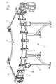
- a Kurvengurt unit 1 is shown in a perspective view.
- This has, on the one hand, a frame 2 on which a conveyor belt 3 revolves, with a difference being made in the conveyor belt between the upper side 4 and the lower side 5.
- deflection rollers 6 are provided, around which the conveyor belt rotates.
- Rollers 20 are provided on a side wall profile 7, which engage a engaging element 8 arranged on the outer edge of the conveyor belt 3 and in this way guide the conveyor belt 3.
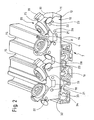
- Fig. 2 is a perspective view of a portion of the side wall profile 7 is shown with a holding member 10 which is fixed to the side wall profile, and on which four rollers 20 are mounted.
- the holding element 10 is designed in the manner of a U-profile and has a bottom 11 or bottom portion, from which extend at right angles two legs 12 and 13 parallel to each other.
- a number of recesses 14 are provided through which a connection of the holding member 10 with the side wall profile 7 takes place.
- a plurality of grooves 15 are provided, in which clamping blocks 16 can be arranged, which are bolted to the holding element 10 through the recesses 14 and fixed.
- the holding element 10 is aligned vertically overall, so that the four rollers 20 are arranged one above the other. Between each pair of rollers which form a pair of rollers, a conveyor belt, in particular an engagement element 8 of the conveyor belt is guided. In the drawing, the engagement element 8 is shown with arms 9 formed therewith. Between these arms 9, the conveyor belt 3 is inserted and connected to the arms, for example by gluing and / or a seam connection.
- the rollers 20 of a pair of rollers are under a wink! between 100 ° and 120 °, in particular 110 ° to each other and thus act on both sides of the engagement element 8 of the conveyor belt 3, the Indian Fig. 2 not shown.
- the rollers 20 are mounted on roller holders 25, which in turn are received in the holding element 10.
- the holding elements 25 are arranged on the opposite legs 12, 13 of the holding element 10, in particular on the inner sides of the legs 12, 13 attached.
- at least one roller 20 is pivotally mounted.
- a plurality of recesses 21, 22, 23 are provided in the legs 12, 13.
- a latching recess 21 is arranged on the conveyor belt side facing the roller 20 and two locking recesses 22 and 23 are arranged at some distance from each other on the side remote from the conveyor belt side of the legs of the U-profile.
- the roller holder 25 has two latching noses 26 and 27, which correspond to the recesses and form with these attachment points.
- the locking lug 26 is firmly locked in the latching recess 21, wherein the roller holder 25 is pivotable about an axis extending through the latching lug 25 axis.
- the latching lug 27 can be moved either into the latching recess 22 or the latching recess 23. In the illustrated in the figure locking the locking lug 27 in the recess 22 of the conveyor belt or the engaging element 8 of the conveyor belt is taken from the rollers 20 into engagement. If the roller holder 25 is moved downwards, so that the latching nose 22 clicks into the latching recess 23, the entire roller 20 is pivoted downwards and the conveyor belt is released and can then be removed for maintenance purposes.
- the change in position takes place on both sides of the roller holder 25 provided actuating lever 29, which can be pressed by an operator inwardly, so that then the locking lug 27 is pushed out of the recess 22 inwardly, can be moved and then upon release of the actuating lever 29th in the desired other position, ie in particular the locking recesses 23 engages again.
- the holding element 10, in particular the legs 12 and 13 of the U-profile have between the paired rollers 20 recesses 18, so that in this the conveyor belt can run.
- the upper portions 19 of the legs 12 and 13 are made at an angle of about 55 ° and inclined towards each other. This upper portion 19 is thus parallel to the arranged in the engagement position rollers 20.
- two pairs of rollers are arranged on the one-piece support member 10.
- two recesses 18 are provided in the legs, which are each arranged between two rollers of a pair of rollers.
- a second recess 28 is arranged between the two roller pairs and serves to allow the roller holders 25 and in particular the actuating levers 29, which protrude beyond the retaining element 10, to be moved downwards.
- Attention is also drawn to an asymmetry resulting from the orientation of the retaining element 10, namely the recess 32 located in the lower end region, by means of which an edge 33 is formed in the region of the bottom 11 of the retaining element 10 which abuts against a projecting shoulder 34 of the side wall profile 7 strikes. The end region is directed downwards, so that the force acting on the holding element 10 can be mechanically supported even better on the side wall profile 7.
- Fig. 3 is a detailed perspective view of the holding member 10 is shown, wherein the right in the Fig. Right roller 20 between the legs 12 and 13 of the U-shaped profile is pivoted. Thereby, the conveyor belt or arranged on the conveyor belt attack element 8 is released and the belt can be removed.
- the locking lug 27 of the roller holder 25 is no longer locked in the latching recess 22, but in the recess 23.
- the roller holder 25 is thus given down and thus also the roller 20 which rotates on the axis 35 of the roller holder 25, swung.
- the distances between the legs 12 and 13 to each other are such that the roller 20 can be swung in between them.
- Fig. 4 a perspective view of a roller holder 25 is shown.
- the axis 35 arranged on the roller holder and the lateral latching noses 26 and 27 and the actuating lever 29 have already been described.
- the axis 35 is arranged on a central and very stable central block 36 which is connected to the two outer side elements 39 via transverse struts 37.
- On the side members 39 which are dimensioned so that they are tightly fitted on the inside between the legs 12 and 13 of the support member, the locking lugs 26 and 27 are formed.
- the side members 39 are in the front region, ie in particular between the belt facing locking lug 26 to the cross brace 37 rigid.
- the side elements 39 In the rear area, that is to say in particular between the transverse strut 37 and the rear latching lug 27, the side elements 39 have a material weakening 40, so that bending of the side elements 39 takes place in a defined manner in this area due to pressure on the actuating lever 39, so that the latching lug 27 protrudes the respective latching recess 22 or 23 can be moved.
Landscapes
- Engineering & Computer Science (AREA)
- Mechanical Engineering (AREA)
- Structure Of Belt Conveyors (AREA)
- Rehabilitation Tools (AREA)
- Rollers For Roller Conveyors For Transfer (AREA)
Description
- Die Erfindung betrifft einen Kurvengurtförderer mit einem Fördergurt, der im Bereich der den Außenrand bildenden Kante ein Angriffselement aufweist, das von mehreren paarweise angeordneten Rollen geführt wird, wobei jedes Rollenpaar auf einem Halteelement angeordnet ist. Weiterhin betrifft die Erfindung ein Halteelement mit einem darauf angeordneten Rollenpaar zur Verwendung in einem solchen Kurvengurtförderer.
- Ein gattungsgemäßer Kurvengurtförderer ist in der
DE 10 2006 024 535 B4 bzw. derEP 2 027 044 A1 beschrieben. Im Bereich des Außenradius sind eine Vielzahl von Rollenpaaren angeordnet, die den Fördergurt an einer wulstartigen Kante in Eingriff nehmen und dadurch führen. Dabei sind in vertikaler Hinsicht jeweils vier Rollen übereinander an einem Halteelement angeordnet, wobei das obere Rollenpaar den obertrumigen Teil des Fördergurtes und das untere Rollenpaar den untertrumigen Teil des Fördergurtes führen. Auf dem Halteelement sind die Rollen mit ihrer Drehachse über einen Hebel exzentrisch, d.h. parallel und beabstandet, zur Drehachse des Schwenkelements gelagert und verschwenkbar. - Eine andere Lösung ist beispielsweise aus der
EP 2 275 365 A1 bekannt, bei der die äußeren Rollen der Rollenpaare an C-förmigen Bügeln angeordnet sind, die nach außen wegschwenkbar sind. - Der Erfindung liegt die Aufgabe zu Grunde einen Kurvengurtförderer der eingangs genannten Art zu schaffen, der insbesondere im Bereich der Führungsrollen besonders einfach und stabil aufgebaut ist.
- Die Lösung dieser Aufgabe erfolgt mit einem Kurvengurtförderer mit den Merkmalen des Patentanspruchs 1. Vorteilhafte Weiterbildungen der Erfindung sind in den Unteransprüchen beschrieben.
- Bei einem Kurvengurtförderer mit einem Fördergurt, der im Bereich der den Außenrand bildenden Kante ein Angriffselement aufweist, das von mehreren paarweise angeordneten Rollen geführt wird, wobei jedes Paar der Rollen auf einem Halteelement angeordnet ist, ist erfindungswesentlich vorgesehen, dass das Halteelement als U-Profil mit einem Boden und zwei Schenkeln ausgebildet ist und dass die Rollen über zugeordnete Rollenhalter an den gegenüberliegenden Schenkeln des U-Profils befestigt sind. Dadurch entsteht ein sehr einfach und zugleich sehr stabil konstruiertes Halteelement. Das Halteelement ist auch in sich stabil und kann ohne weiteres an anderen Elementen wie einem äußeren Rahmen des Kurvengurtförderers montiert werden, wobei dann die anderen Elemente nicht mehr die Gesamtstabilität zur Aufnahme der Rollen aufbringen müssen, da dies durch das U-Profil erreicht wird.
- Bevorzugt ist jede Rolle auf einem Rollenhalter gelagert und jeder Rollenhalter ist an den Schenkeln des U-Profils befestigt. Der Rollenhalter ist dabei auf beiden Seiten des U-Profils, also an beiden sich gegenüberliegenden Schenkeln des U-Profils und dabei bevorzugt auf den innenliegenden Seiten der Schenkel des U-Profils befestigt. Der Abstand der Schenkel des U-Profils entspricht dabei bevorzugt im wesentlichen etwa dem Durchmesser der Rollen bzw. ist etwas größer ausgebildet. Die Rollen sind dann durch den zwischen den Schenkeln angeordneten Rollenhalter etwas oberhalb der Schenkel angeordnet, können aber zwischen die Schenkel verschwenkt werden. Insgesamt ergibt sich auf diese Weise eine sehr hohe Stabilität.
- In einer bevorzugten Ausgestaltung der Erfindung ist die Drehachse mindestens einer Rolle von zwei paarweise angeordneten Rollen in einer Ebene verschwenkbar, die parallel zwischen den Schenkeln des U-Profils liegt. Dadurch kann mindestens eine Rolle eines Rollenpaars vom Fördergurt weg und zum Fördergurt hin bewegt werden. Der zwischen den Rollen mit dem Angriffselement eingespannte Fördergurt kann dann leicht entnommen und gegebenenfalls erneuert werden. Eine Wartung des erfindungsgemäßen Kurvengurtförderers ist dadurch sehr leicht möglich. Dazu weist der Rollenhalter für mindestens eine Rolle an jedem Schenkel zwei Befestigungspunkte auf, wobei der Befestigungspunkt, der dem Fördergurt zugewandt ist, eine Drehbewegung um diesen Befestigungspunkt ermöglicht und der Befestigungspunkt, der vom Fördergurt abgewandt ist, zwischen zwei Positionen so verstellbar ist, dass in einer Position die Rolle am Fördergurt anliegt und in einer anderen Position die Rolle den Fördergurt freigibt. Die Rolle wird dabei in einer Ebene geschwenkt, in der auch die Drehachse der Rolle liegt. Der gesamte Rollenhalter wird dabei zwischen die Schenkel des U-Profils verschwenkt. Der Abstand der Schenkel zueinander ist so groß, dass die Rolle ebenfalls zwischen die Schenkel schwenkbar ist.
- Um eine solche Schwenkbarkeit zu realisieren, ist der Rollenhalter bevorzugt mechanisch verformbar, so dass ein Befestigungspunkt des Rollenhalters reversibel lösbar ist. Günstigerweise ist dabei der vom Fördergurt abgewandte Befestigungspunkt reversibel lösbar. Ein Befestigungspunkt ist bevorzugt durch korrespondierende Rastelemente an einem Betätigungshebel des Rollenhalters und dem zugeordnetem Schenkel des U-Profils ausgebildet. In einer Ausgestaltung weist der Betätigungshebel eine Rastnase auf, die innenseitig in eine von mehreren Rastausnehmungen im Schenkel des U-Profils reversibel fixierbar ist. Denkbar ist auch eine umgekehrte Ausbildung, bei der eine Rastausnehmung im Betätigungshebel vorgesehen ist, die auf eine von mehreren vorstehenden Rastnasen an den Schenkeln aufgeschoben wird. In den Schenkeln des U-Profils sind bevorzugt zwei Rastelemente, insbesondere Rastausnehmungen vorgesehen, so dass die Rolle in einer ersten Position fixierbar ist, in der diese den Fördergurt bzw. das Angriffselement, insbesondere einen wulstförmigen Rand, in Eingriff nimmt und in einer zweiten Position fixierbar ist, in der die Rolle den Fördergurt freigibt, so dass dieser entnommen bzw. ausgetauscht werden kann. Der Rollenhalter ist günstigerweise im Bereich des dem Fördergurt zugewandten Befestigungspunktes und der Aufnahme der Rolle starr ausgebildet und ist demgegenüber im Bereich des vom Fördergurt abgewandten Befestigungspunktes, insbesondere im Bereich des Betätigungshebels weniger starr ausgebildet. Bevorzugt ist der Rollenhalter aus Kunststoff, insbesondere als Spritzgussteil ausgebildet, wobei die einzelnen Wandabschnitte des Spritzgussteils so stark ausgebildet sind, dass der Rollenhalter eine ausreichende Stabilität zur Aufnahme und Lagerung der Rolle aufweist. Im Bereich der Betätigungshebel ist die Wand jedoch mit einer Schwächung oder Verjüngung ausgebildet, so dass die Betätigungshebel bewegbar sind, insbesondere zwischen den Schenkeln des U-Profils nach innen gedrückt werden können, so dass die nach außen vorstehenden Rastnasen aus den Rastausnehmungen in den Schenkeln herausdrückbar sind.
- In einer anderen bevorzugten Ausgestaltung der Schenkel weisen die Schenkel des U-Profils zwischen zwei ein Rollenpaar bildenden Rollen eine Ausnehmung auf. In dieser Ausnehmung kann der Fördergurt und insbesondere das Angriffselement an der äußeren Kante des Fördergurts zwischen den ein Rollenpaar bildenden Rollen hindurchgeführt werden ohne mit den Schenkeln des U-Profils zu kollidieren. In einer bevorzugten Ausgestaltung der Erfindung sind auf einem einstückig ausgebildeten U-Profil vier Rollen angeordnet, wobei zwei Rollen ein Rollenpaar für die obertrumige Seite des Fördergurtes und zwei Rollen ein Rollenpaar für die untertrumige Seite des Fördergurtes bilden. Jedes U-Profil ist dabei zur vertikalen Anordnung an dem Kurvengurtförderer, insbesondere einem Seitenwandprofil vorgesehen. Bevorzugt sind im Boden des U-Profils Ausnehmungen vorgesehen, durch die eine Verbindung des U-Profils mit dem Seitenwandprofil über Schrauben und Klemmsteine möglich ist. Bevorzugt weisen die Schenkel des U-Profils im Bereich zwischen den Rollenpaaren eine weitere Ausnehmung auf. Diese Ausnehmung ist so dimensioniert, dass die Betätigungshebel der Rollenhalter in dieser Ausnehmung hin und her bewegt werden können, so dass die Verschwenkbarkeit auch der mittleren Rollen der vier auf dem Halteelement angeordneten Rollen gegeben ist.
- Ein weiterer Aspekt der Erfindung besteht in der Bereitstellung eines Halteelements für einen Kurvengurtförderer der oben genannten Gattung, auf dem wenigstens zwei ein Rollenpaar bildende Rollen angeordnet sind, wobei das Halteelement als U-Profil mit einem Boden und zwei Schenkeln ausgebildet ist und die Rollen an den gegenüberliegenden Schenkeln des U-Profils befestigt sind. Hinsichtlich der weiteren Ausgestaltung eines solchen Halteelements wird auf die oben gegebene Beschreibung des Kurvengurtförderers verwiesen, bei dem ebenfalls dieses Halteelement ausführlich diskutiert wurde.
- Nachfolgend wird die Erfindung anhand eines in der Zeichnung dargestellten Ausführungsbeispiels weiter erläutert. Im Einzelnen zeigen die schematischen Darstellungen in:
- Fig. 1:
- eine schematische Ansicht eines Kurvengurtförderers;
- Fig. 2:
- eine perspektivische Ansicht eines Halteelements des erfindungsgemäßen Kurvengurtförderers montiert in einem Seitenteil des Kurvengurtförderers;
- Fig. 3:
- eine perspektivische Detailansicht eines Halteelements im Zustand bei wechselbarem Fördergurt;
- Fig. 4:
- eine perspektivische Ansicht eines Rollenhalters.
- In
Fig. 1 ist ein Kurvengurtförderer 1 in perspektivischer Ansicht dargestellt. Diese weist zum einen ein Gestell 2 auf, auf dem ein Fördergurt 3 umläuft, wobei bei dem Fördergurt zwischen der obertrumigen Seite 4 und der untertrumigen Seite 5 unterschieden wird. An den beiden Enden des Kurvengurtförderers sind Umlenkrollen 6 vorgesehen, um die der Fördergurt umläuft. An einem Seitenwandprofil 7 sind Rollen 20 vorgesehen, die ein an der Außenkante des Fördergurtes 3 angeordnetes Angriffselement 8 in Eingriff nehmen und auf diese Weise den Fördergurt 3 führen. - In
Fig. 2 ist eine perspektivische Ansicht eines Teils des Seitenwandprofils 7 mit einem Halteelement 10 dargestellt, das an dem Seitenwandprofil befestigt ist, und an dem vier Rollen 20 montiert sind. Das Halteelement 10 ist nach Art eines U-Profils ausgebildet und weist einen Boden 11 oder Bodenabschnitt auf, von dem aus sich rechtwinklig zwei Schenkel 12 und 13 parallel zueinander erstrecken. Im Boden 11 des Halteelements 10, das als U-Profil ausgebildet ist, sind einige Ausnehmungen 14 vorgesehen, durch die eine Verbindung des Halteelements 10 mit dem Seitenwandprofil 7 erfolgt. In dem Seitenwandprofil 7 sind mehrere Nuten 15 vorgesehen, in denen Klemmsteine 16 angeordnet werden können, die mit dem Halteelement 10 durch die Ausnehmungen 14 hindurch verschraubt und festgelegt werden. Das Haltelement 10 ist insgesamt vertikal ausgerichtet, so dass die vier Rollen 20 übereinander angeordnet sind. Zwischen jeweils zwei Rollen, die ein Rollenpaar bilden, ist ein Fördergurt, insbesondere ein Angriffselement 8 des Fördergurts geführt. In der Zeichnung ist das Angriffselement 8 mit damit ausgebildeten Armen 9 dargestellt. Zwischen diese Arme 9 ist der Fördergurt 3 eingelegt und mit den Armen verbunden, beispielsweise durch Verklebung und/oder eine Nahtverbindung. Die Rollen 20 eines Rollenpaars stehen unter einem Winke! zwischen 100 ° und 120 °, insbesondere 110 ° zueinander und beaufschlagen so von beiden Seiten das Angriffselement 8 des Fördergurts 3, der in derFig. 2 nicht dargestellt ist. Die Rollen 20 sind auf Rollenhaltern 25 gelagert, die ihrerseits in dem Halteelement 10 aufgenommen sind. Die Halteelemente 25 sind an den sich gegenüberliegenden Schenkeln 12, 13 des Halteelements 10 angeordnet, insbesondere an den Innenseiten der Schenkel 12, 13 befestigt. Um den Fördergurt und insbesondere das Angriffselement 8 aus der Position zwischen den Rollen herausnehmen zu können, ist es notwendig, dass mindestens eine Rolle 20 schwenkbar angeordnet ist. Dazu sind in den Schenkeln 12, 13 mehrere Rastausnehmungen 21, 22, 23 vorgesehen. Dabei ist eine Rastausnehmung 21 auf der dem Fördergurt zugewandten Seite der Rolle 20 angeordnet und zwei Rastausnehmungen 22 und 23 sind mit etwas Abstand zueinander auf der vom Fördergurt abgewandten Seite den Schenkeln des U-Profils angeordnet. Der Rollenhalter 25 weist zwei Rastnasen 26 und 27 auf, die zu den Rastausnehmungen korrespondieren und mit diesen Befestigungspunkte ausbilden. Die Rastnase 26 ist fest in der Rastausnehmung 21 arretiert, wobei der Rollenhalter 25 um eine durch die Achse der Rastnase 25 verlaufende Achse schwenkbar ist. Auf der vom Fördergurt abgewandten Seite kann die Rastnase 27 entweder in die Rastausnehmung 22 oder die Rastausnehmung 23 bewegt werden. Bei der in der Figur dargestellten Arretierung der Rastnase 27 in der Rastausnehmung 22 wird der Fördergurt bzw. das Angriffselement 8 des Fördergurts von den Rollen 20 in Eingriff genommen. Wird der Rollenhalter 25 nach unten bewegt, so dass die Rastnase 22 in die Rastausnehmung 23 einklickt, wird dabei die gesamte Rolle 20 nach unten geschwenkt und der Fördergurt wird freigegeben und kann dann zu Wartungszwecken entnommen werden. - Die Veränderung der Position erfolgt über beidseitig an dem Rollenhalter 25 vorgesehene Betätigungshebel 29, die von einem Bediener nach innen gedrückt werden können, so dass dann die Rastnase 27 aus der Rastausnehmung 22 nach innen herausgedrückt wird, verschoben werden kann und dann bei Loslassen des Betätigungshebels 29 in die gewünschte andere Position, also insbesondere die Rastausnehmungen 23 wieder einrastet. Das Halteelement 10, insbesondere die Schenkel 12 und 13 des U-Profils weisen zwischen den paarweise angeordneten Rollen 20 Aussparungen 18 auf, so dass in diesen der Fördergurt verlaufen kann. Zu beiden Seiten der Aussparung 18 sind die oberen Abschnitte 19 der Schenkel 12 und 13 mit einem Winkel von etwa 55 ° angestellt und einander zugeneigt. Dieser obere Abschnitt 19 ist somit parallel zu dem in der Eingriffshaltung angeordneten Rollen 20. Auf dem einstückigen Halteelement 10 sind zwei Rollenpaare angeordnet. Dabei sind zwei Aussparungen 18 in den Schenkeln vorgesehen, die jeweils zwischen zwei Rollen eines Rollenpaares angeordnet sind. Eine zweite Aussparung 28 ist zwischen den beiden Rollenpaaren angeordnet und dient dazu, dass die Rollenhalter 25 und insbesondere die Betätigungshebel 29, die über das Halteelement 10 hinausstehen, nach unten bewegt werden können. Hinzuweisen ist außerdem noch auf eine sich aus der Ausrichtung des Halteelements 10 ergebende Asymmetrie, nämlich die im unterem Endbereich befindliche Aussparung 32, durch die im Bereich des Bodens 11 des Halteelements 10 eine Kante 33 gebildet ist, die gegen eine vorspringenden Absatz 34 des Seitenwandprofils 7 anschlägt. Der Endbereich ist nach unten gerichtet, so dass die auf das Halteelement 10 wirkende Kraft mechanisch noch besser auf dem Seitenwandprofil 7 abgestützt werden kann.
- In
Fig. 3 ist eine perspektivische Detailansicht des Halteelements 10 dargestellt, wobei die in der Fig. rechte Rolle 20 zwischen die Schenkel 12 und 13 des U-förmigen Profils geschwenkt ist. Dadurch wird der Fördergurt bzw. das an dem Fördergurt angeordnete Angriffselement 8 freigegeben und der Gurt kann herausgenommen werden. Im Unterschied zuFig. 2 ist hier klar zu erkennen, dass die Rastnase 27 des Rollenhalters 25 jetzt nicht mehr in der Rastausnehmung 22, sondern in Rastausnehmung 23 arretiert ist. Der Rollenhalter 25 ist also nach unten geschenkt und damit ist auch die Rolle 20, die auf der Achse 35 des Rollenhalters 25 dreht, mitgeschwenkt. Die Abstände der Schenkel 12 und 13 zueinander sind so bemessen, dass die Rolle 20 zwischen diese gerade eingeschwenkt werden kann. - In
Fig. 4 ist eine perspektivische Ansicht eines Rollenhalters 25 dargestellt. Bereits beschrieben wurde die auf dem Rollenhalter angeordnete Achse 35 sowie die seitlichen Rastnasen 26 und 27 und der Betätigungshebel 29. Die Achse 35 ist auf einem zentralen und sehr stabilen Mittelblock 36 angeordnet, der über Querverstrebungen 37 mit den beiden äußeren Seitenelementen 39 verbunden ist. An den Seitenelementen 39, die so dimensioniert sind, dass sie innenseitig eng anliegend zwischen die Schenkel 12 und 13 des Halteelements eingepasst sind, sind die Rastnasen 26 und 27 angeformt. Die Seitenelemente 39 sind im vorderen Bereich, also insbesondere zwischen dem Gurt zugewandten Rastnase 26 bis zur Querverstrebung 37 starr ausgebildet. Im hinteren Bereich, also insbesondere zwischen der Querverstrebung 37 und der hinteren Rastnase 27 weisen die Seitenelemente 39 eine Materialschwächung 40 auf, so dass durch Druck auf den Betätigungshebel 39 eine in diesem Bereich definiert erfolgende Biegung der Seitenelemente 39 erfolgt, so dass die Rastnase 27 aus der jeweiligen Rastausnehmung 22 oder 23 bewegt werden kann.
Claims (14)
- Kurvengurtförderer mit einem Fördergurt (3), der im Bereich der den Außenrand bildenden Kante ein Angriffselement (8) aufweist, das von mehreren paarweise angeordneten Rollen (20) geführt wird, wobei jedes Paar der Rollen (20) auf einem Halteelement (10) angeordnet ist,
dadurch gekennzeichnet,
dass das Haltelement (10) als U-Profil mit einem Boden (11) und zwei Schenkeln (12, 13) ausgebildet ist, und
dass die Rollen (20) über zugeordnete Rollenhalter (25) an den sich gegenüberliegenden Schenkeln (12, 13) des U-Profils befestigt sind. - Kurvengurtförderer nach Anspruch 1, dadurch gekennzeichnet, dass der Rollenhalter (25) an den Innenseiten der sich gegenüberliegenden Schenkel (12, 13) des U-Profils befestigt ist.
- Kurvengurtförderer nach einem der vorhergehenden Ansprüche, dadurch gekennzeichnet, dass die Drehachse (35) mindestens einer Rolle in einer Ebene, die parallel zwischen den Schenkeln (12, 13) des U-Profils liegt, verschwenkbar ist.
- Kurvengurtförderer nach einem der vorhergehenden Ansprüche, dadurch gekennzeichnet, dass mindestens ein Rollenhalter (25) mit jedem Schenkel (12, 13) des U-Profils zwei Befestigungspunkte hat, wobei der Befestigungspunkt (21, 26), der dem Fördergurt (7) zugewandt ist, eine Drehbewegung des Rollenhalters (25) um diesen Befestigungspunkt (21, 26) erlaubt und dass der Befestigungspunkt (22, 23, 27), der vom Fördergurt (7) abgewandt ist, zwischen zwei Positionen veränderbar ist, so dass in einer Position die Rolle (20) am Fördergurt (7) anliegt und in einer anderen Position die Rolle der Fördergurt freigibt.
- Kurvengurtförderer nach einem der vorhergehenden Ansprüche, dadurch gekennzeichnet, dass der Abstand der Schenkel (12, 13) des U-Profils zueinander größer ist als der Durchmesser der Rolle (20).
- Kurvengurtförderer nach einem der vorhergehenden Ansprüche, dadurch gekennzeichnet, dass der Rollenhalter (25) einen Betätigungshebel (29) aufweist, der mechanisch verformbar ist, so dass ein Befestigungspunkt (22, 23,27) des Rollenhalters (25) reversibel lösbar ist.
- Kurvengurtförderer nach Anspruch 6, dadurch gekennzeichnet, dass ein Befestigungspunkt durch korrespondierende Rastelemente am Betätigungshebel des Rollenhalters und dem Schenkel des U-Profils ausgebildet ist.
- Kurvengurtförderer nach einem der Ansprüche 6 oder 7, dadurch gekennzeichnet, dass der Betätigungshebel (28) eine Rastnase (27) aufweist, die innenseitig in einer von mehreren Rastausnehmungen (22, 23) in den Schenkel (12, 13) des U-Profils reversibel fixierbar ist.
- Kurvengurtförderer nach einem der Ansprüche 4 bis 8, dadurch gekennzeichnet, dass der Rollenhalter (25) im Bereich des dem Fördergurt (7) zugewandten Befestigungspunktes und der Aufnahme der Rolle starr ausgebildet ist und dass der Rollenhalter im Bereich des vom Fördergurt abgewandten Befestigungspunktes weniger starr ausgebildet ist.
- Kurvengurtförderer nach Anspruch 9, dadurch gekennzeichnet, dass der Rollenhalter Seitenelemente (39) aufweist, die im Übergangsbereich zum Betätigungshebel (29) eine Materialschwächung (40) aufweisen.
- Kurvengurtförderer nach einem der vorhergehenden Ansprüche, dadurch gekennzeichnet, dass die Schenkel(12, 13) des U-Profils zwischen zwei ein Rollenpaar bilden Rollen (20) eine Ausnehmung (18) aufweisen.
- Kurvengurtförderer nach einem der vorhergehenden Ansprüche, dadurch gekennzeichnet, dass auf einem einstückig ausgebildeten U-Profil vier Rollen angeordnet sind, wobei zwei Rollen ein Rollenpaar für die obertrumige Seite des Fördergurtes bilden und zwei Rollen ein Rollenpaar für die untertrumige Seite des Fördergurtes bilden.
- Kurvengurtförderer nach Anspruch 12, dadurch gekennzeichnet, dass die Schenkel (12, 13) des U-Profils im Bereich zwischen den Rollenpaaren eine Aussparung (28) aufweisen.
- Halteelement für einen Kurvengurtförderer, auf dem mindestens zwei paarweise angeordnete Rollen angeordnet sind,
dadurch gekennzeichnet,
dass das Halteelement als U-Profil mit einem Boden und zwei Schenkeln ausgebildet ist, und
dass die Rollen (20) über zugeordnete Rollenhalter (25) an den sich gegenüberliegenden Schenkeln (12, 13) des U-Profils befestigt sind.
Applications Claiming Priority (1)
| Application Number | Priority Date | Filing Date | Title |
|---|---|---|---|
| PCT/DE2011/000410 WO2012139538A1 (de) | 2011-04-14 | 2011-04-14 | Kurvengurtförderer und halteelement mit rollen für einen kurvengurtförderer |
Publications (2)
| Publication Number | Publication Date |
|---|---|
| EP2697140A1 EP2697140A1 (de) | 2014-02-19 |
| EP2697140B1 true EP2697140B1 (de) | 2014-09-17 |
Family
ID=44627066
Family Applications (1)
| Application Number | Title | Priority Date | Filing Date |
|---|---|---|---|
| EP11725312.0A Active EP2697140B1 (de) | 2011-04-14 | 2011-04-14 | Kurvengurtförderer und halteelement mit rollen für einen kurvengurtförderer |
Country Status (10)
| Country | Link |
|---|---|
| US (1) | US9120628B2 (de) |
| EP (1) | EP2697140B1 (de) |
| JP (1) | JP5714174B2 (de) |
| KR (1) | KR101660098B1 (de) |
| CN (1) | CN103582602B (de) |
| BR (1) | BR112013026204B1 (de) |
| CA (1) | CA2832351A1 (de) |
| DK (1) | DK2697140T3 (de) |
| ES (1) | ES2526146T3 (de) |
| WO (1) | WO2012139538A1 (de) |
Cited By (2)
| Publication number | Priority date | Publication date | Assignee | Title |
|---|---|---|---|---|
| JP2014510685A (ja) * | 2011-04-14 | 2014-05-01 | トランスノーム システム ゲゼルシャフト ミット ベシュレンクテル ハフツング | カーブベルトコンベヤ及びカーブベルトコンベヤ用のローラを備えた保持エレメント |
| US20140367228A1 (en) * | 2013-06-14 | 2014-12-18 | James Laverdiere | Conveyor assembly and associated method |
Families Citing this family (12)
| Publication number | Priority date | Publication date | Assignee | Title |
|---|---|---|---|---|
| NL2009721C2 (nl) * | 2012-10-29 | 2014-05-01 | Rexnord Flattop Europe Bv | Eindaandrijving voor een transporteur, transporteur voorzien van een eindaandrijving, en aandrijftandwiel voor een eindaandrijving. |
| FR3017379B1 (fr) * | 2014-02-13 | 2017-11-24 | Ceric | Table pour convoyeur a bande, procede de montage et procede de demontage d'un convoyeur a bande comprenant la table |
| US9776795B2 (en) * | 2014-08-15 | 2017-10-03 | Sanki Engineering Co., Ltd. | Curved belt conveyor apparatus |
| KR102208735B1 (ko) | 2015-07-09 | 2021-01-28 | 삼성전자 주식회사 | 금속 하우징을 가지는 전자 장치 및 그 제조 방법 |
| MY201220A (en) | 2018-06-12 | 2024-02-09 | Kairos Conveyor Sdn Bhd | A rapid release mechanism for a curved belt conveyor and a method of using the rapid release mechanism thereof |
| CN109775237B (zh) * | 2019-01-21 | 2021-03-26 | 金锋馥(滁州)输送机械有限公司 | 一种环形输送带 |
| EP3715286B1 (de) * | 2019-03-28 | 2021-10-06 | BEUMER Group GmbH & Co. KG | Verstellbarer einklemmschutz für gurtförderer |
| CN114043263B (zh) * | 2021-11-08 | 2023-11-21 | 陕西飞机工业有限责任公司 | 一种曲度带弯边零件弯边边缘精度铣切导轨夹具 |
| MY210393A (en) | 2022-02-15 | 2025-09-18 | Kairos Global Sdn Bhd | Rapid release belt guidance mechanism |
| IT202200003830A1 (it) | 2022-03-01 | 2023-09-01 | Mech Sistemi S R L | Curved belt conveyor |
| DE102023102117A1 (de) | 2023-01-30 | 2024-08-01 | Schmid Systemtechnik GmbH | Gurtniederhalter und Gurtförderer |
| EP4669601A1 (de) | 2023-02-20 | 2025-12-31 | Kairos Global Sdn. Bhd. | Mechanische befestigungsstrukturanordnung und verfahren zur verwendung für gekrümmte förderbänder |
Family Cites Families (19)
| Publication number | Priority date | Publication date | Assignee | Title |
|---|---|---|---|---|
| JPS5444942Y2 (de) * | 1977-08-18 | 1979-12-24 | ||
| JPS61163210U (de) * | 1985-03-29 | 1986-10-09 | ||
| DE3826953A1 (de) * | 1988-08-09 | 1990-03-01 | Transnorm System Gmbh | Kurvengurtfoerderer |
| DE9300876U1 (de) * | 1993-01-25 | 1993-05-06 | Transnorm-System-GmbH, 3207 Harsum | Kurvengurtförderer |
| DK170746B1 (da) | 1993-05-26 | 1996-01-08 | Seelen As | Kurveformet bæltetransportør |
| US5394977A (en) * | 1993-07-08 | 1995-03-07 | Portec, Inc. | Apparatus and method for use in replacing conveyor belts |
| GB9321728D0 (en) * | 1993-10-21 | 1993-12-15 | Gramac Mechanical Handling Lim | Improvements relating to conveyors |
| NL9402081A (nl) * | 1994-12-09 | 1996-07-01 | Vanderlande Ind Nederland | Transportinrichting. |
| DE29502064U1 (de) * | 1995-02-10 | 1995-06-01 | Transnorm-System-GmbH, 31177 Harsum | Kurvengurtförderer |
| NL1004699C2 (nl) | 1996-12-05 | 1998-06-08 | Vanderlande Ind Nederland | Transportinrichting. |
| JP4445076B2 (ja) * | 1999-10-26 | 2010-04-07 | バンドー化学株式会社 | 湾曲走行ベルトコンベヤ |
| JP3430143B2 (ja) * | 2000-10-11 | 2003-07-28 | ハバジット日本株式会社 | カーブベルトの支持装置 |
| US7232030B2 (en) * | 2004-11-24 | 2007-06-19 | Transnorm System Inc. | Quick release holder for a beading of a conveyor belt and method of using quick release holder |
| JP4708805B2 (ja) | 2005-02-04 | 2011-06-22 | 三機工業株式会社 | ベルトカーブコンベヤ |
| WO2006084407A1 (de) * | 2005-02-10 | 2006-08-17 | Robert Bosch Gmbh | Kurvenbandförderer |
| DE102006024536C5 (de) * | 2006-05-23 | 2012-10-18 | Logcomp Gmbh | Kurvengurtförderer |
| CN201086992Y (zh) * | 2007-03-22 | 2008-07-16 | 新田株式会社 | 皮带保持装置 |
| EP2275365A1 (de) | 2009-07-17 | 2011-01-19 | Cecilia Vila Torra | Halter und Führungssystem für gebogene Förderbänder |
| EP2697140B1 (de) * | 2011-04-14 | 2014-09-17 | TRANSNORM SYSTEM GmbH | Kurvengurtförderer und halteelement mit rollen für einen kurvengurtförderer |
-
2011
- 2011-04-14 EP EP11725312.0A patent/EP2697140B1/de active Active
- 2011-04-14 ES ES11725312.0T patent/ES2526146T3/es active Active
- 2011-04-14 DK DK11725312.0T patent/DK2697140T3/en active
- 2011-04-14 CA CA2832351A patent/CA2832351A1/en not_active Abandoned
- 2011-04-14 KR KR1020137026722A patent/KR101660098B1/ko active Active
- 2011-04-14 WO PCT/DE2011/000410 patent/WO2012139538A1/de not_active Ceased
- 2011-04-14 CN CN201180070122.2A patent/CN103582602B/zh active Active
- 2011-04-14 JP JP2014504154A patent/JP5714174B2/ja active Active
- 2011-04-14 US US14/110,771 patent/US9120628B2/en active Active
- 2011-04-14 BR BR112013026204-4A patent/BR112013026204B1/pt active IP Right Grant
Cited By (3)
| Publication number | Priority date | Publication date | Assignee | Title |
|---|---|---|---|---|
| JP2014510685A (ja) * | 2011-04-14 | 2014-05-01 | トランスノーム システム ゲゼルシャフト ミット ベシュレンクテル ハフツング | カーブベルトコンベヤ及びカーブベルトコンベヤ用のローラを備えた保持エレメント |
| US20140367228A1 (en) * | 2013-06-14 | 2014-12-18 | James Laverdiere | Conveyor assembly and associated method |
| US9227784B2 (en) * | 2013-06-14 | 2016-01-05 | Kleenline Llc | Conveyor assembly and associated method |
Also Published As
| Publication number | Publication date |
|---|---|
| KR20140010140A (ko) | 2014-01-23 |
| CN103582602A (zh) | 2014-02-12 |
| US9120628B2 (en) | 2015-09-01 |
| ES2526146T3 (es) | 2015-01-07 |
| EP2697140A1 (de) | 2014-02-19 |
| HK1191625A1 (zh) | 2014-08-01 |
| JP2014510685A (ja) | 2014-05-01 |
| KR101660098B1 (ko) | 2016-09-26 |
| BR112013026204A2 (pt) | 2019-09-17 |
| CN103582602B (zh) | 2015-12-16 |
| WO2012139538A1 (de) | 2012-10-18 |
| BR112013026204B1 (pt) | 2020-09-29 |
| JP5714174B2 (ja) | 2015-05-07 |
| US20140027248A1 (en) | 2014-01-30 |
| DK2697140T3 (en) | 2015-01-05 |
| CA2832351A1 (en) | 2012-10-18 |
Similar Documents
| Publication | Publication Date | Title |
|---|---|---|
| WO2012139538A1 (de) | Kurvengurtförderer und halteelement mit rollen für einen kurvengurtförderer | |
| EP3718185B1 (de) | Abisolierzange | |
| DE19729444B4 (de) | Stapelsäule zum Lagern von Lagergütern | |
| DE29914501U1 (de) | Innenrückblickspiegel für Fahrzeuge | |
| EP3016551B1 (de) | Fachbodenelement für einen fachboden eines regales, insbesondere rutschregales, sowie fachbodenrahmen, fachboden und regal | |
| EP3491966B1 (de) | Verbindungsvorrichtung und möbel oder haushaltsgerät | |
| WO2019105702A2 (de) | Klemmbacken und schneiden für eine abisolierzange, sowie abisolierzange | |
| DE202006004641U1 (de) | Greifelement | |
| EP3403738A1 (de) | Blechbiegemaschine | |
| EP3448739A1 (de) | Von hand bewegbares transportgerät | |
| DE202016101921U1 (de) | Haltevorrichtung für ein Zweirad und Zweiradparkanlage | |
| EP1802835A1 (de) | Klemmverbindung zwischen dem klemmschuh eines rollenwagens und einem schiebeflügel | |
| DE102014102626B4 (de) | Kettenglied für eine Energieführungskette | |
| DE102016101466B4 (de) | Fahrradbremse | |
| WO2019007798A1 (de) | Vorrichtung zum führen von behälter für einen förderer | |
| DE19931953A1 (de) | Beschlag zur Lagerung eines Endes einer Latte eines Lattenrahmens | |
| DE2218832A1 (de) | Hebeklemme | |
| EP3359478B1 (de) | Faltriemen für eine vorrichtung zum falten von faltschachtelzuschnitten | |
| EP3737262B1 (de) | Anordnung aus ausziehführung und mitnehmer | |
| DE4225833C2 (de) | Biegevorrichtung für Hohlprofile | |
| EP3894326B1 (de) | Tubenhalter für eine tubenfüllmaschine | |
| DE202015104529U1 (de) | Pflanzenkastenhalter | |
| DE102007039848A1 (de) | Schwenkbiegemaschine | |
| EP2840049B1 (de) | Vorrichtung zum Transportieren eines Prospekts | |
| EP2431616B1 (de) | Klemmbügel |
Legal Events
| Date | Code | Title | Description |
|---|---|---|---|
| PUAI | Public reference made under article 153(3) epc to a published international application that has entered the european phase |
Free format text: ORIGINAL CODE: 0009012 |
|
| 17P | Request for examination filed |
Effective date: 20130928 |
|
| AK | Designated contracting states |
Kind code of ref document: A1 Designated state(s): AL AT BE BG CH CY CZ DE DK EE ES FI FR GB GR HR HU IE IS IT LI LT LU LV MC MK MT NL NO PL PT RO RS SE SI SK SM TR |
|
| GRAP | Despatch of communication of intention to grant a patent |
Free format text: ORIGINAL CODE: EPIDOSNIGR1 |
|
| DAX | Request for extension of the european patent (deleted) | ||
| INTG | Intention to grant announced |
Effective date: 20140522 |
|
| GRAS | Grant fee paid |
Free format text: ORIGINAL CODE: EPIDOSNIGR3 |
|
| GRAA | (expected) grant |
Free format text: ORIGINAL CODE: 0009210 |
|
| AK | Designated contracting states |
Kind code of ref document: B1 Designated state(s): AL AT BE BG CH CY CZ DE DK EE ES FI FR GB GR HR HU IE IS IT LI LT LU LV MC MK MT NL NO PL PT RO RS SE SI SK SM TR |
|
| REG | Reference to a national code |
Ref country code: GB Ref legal event code: FG4D Free format text: NOT ENGLISH |
|
| REG | Reference to a national code |
Ref country code: CH Ref legal event code: EP |
|
| REG | Reference to a national code |
Ref country code: IE Ref legal event code: FG4D Free format text: LANGUAGE OF EP DOCUMENT: GERMAN |
|
| REG | Reference to a national code |
Ref country code: CH Ref legal event code: NV Representative=s name: PATENTANWAELTE SCHAAD, BALASS, MENZL AND PARTN, CH Ref country code: AT Ref legal event code: REF Ref document number: 687588 Country of ref document: AT Kind code of ref document: T Effective date: 20141015 |
|
| REG | Reference to a national code |
Ref country code: DE Ref legal event code: R096 Ref document number: 502011004411 Country of ref document: DE Effective date: 20141030 |
|
| REG | Reference to a national code |
Ref country code: NL Ref legal event code: T3 |
|
| REG | Reference to a national code |
Ref country code: DK Ref legal event code: T3 Effective date: 20141218 |
|
| REG | Reference to a national code |
Ref country code: ES Ref legal event code: FG2A Ref document number: 2526146 Country of ref document: ES Kind code of ref document: T3 Effective date: 20150107 |
|
| PG25 | Lapsed in a contracting state [announced via postgrant information from national office to epo] |
Ref country code: NO Free format text: LAPSE BECAUSE OF FAILURE TO SUBMIT A TRANSLATION OF THE DESCRIPTION OR TO PAY THE FEE WITHIN THE PRESCRIBED TIME-LIMIT Effective date: 20141217 Ref country code: SE Free format text: LAPSE BECAUSE OF FAILURE TO SUBMIT A TRANSLATION OF THE DESCRIPTION OR TO PAY THE FEE WITHIN THE PRESCRIBED TIME-LIMIT Effective date: 20140917 Ref country code: LT Free format text: LAPSE BECAUSE OF FAILURE TO SUBMIT A TRANSLATION OF THE DESCRIPTION OR TO PAY THE FEE WITHIN THE PRESCRIBED TIME-LIMIT Effective date: 20140917 Ref country code: FI Free format text: LAPSE BECAUSE OF FAILURE TO SUBMIT A TRANSLATION OF THE DESCRIPTION OR TO PAY THE FEE WITHIN THE PRESCRIBED TIME-LIMIT Effective date: 20140917 Ref country code: GR Free format text: LAPSE BECAUSE OF FAILURE TO SUBMIT A TRANSLATION OF THE DESCRIPTION OR TO PAY THE FEE WITHIN THE PRESCRIBED TIME-LIMIT Effective date: 20141218 |
|
| REG | Reference to a national code |
Ref country code: LT Ref legal event code: MG4D |
|
| PG25 | Lapsed in a contracting state [announced via postgrant information from national office to epo] |
Ref country code: HR Free format text: LAPSE BECAUSE OF FAILURE TO SUBMIT A TRANSLATION OF THE DESCRIPTION OR TO PAY THE FEE WITHIN THE PRESCRIBED TIME-LIMIT Effective date: 20140917 Ref country code: RS Free format text: LAPSE BECAUSE OF FAILURE TO SUBMIT A TRANSLATION OF THE DESCRIPTION OR TO PAY THE FEE WITHIN THE PRESCRIBED TIME-LIMIT Effective date: 20140917 Ref country code: LV Free format text: LAPSE BECAUSE OF FAILURE TO SUBMIT A TRANSLATION OF THE DESCRIPTION OR TO PAY THE FEE WITHIN THE PRESCRIBED TIME-LIMIT Effective date: 20140917 Ref country code: CY Free format text: LAPSE BECAUSE OF FAILURE TO SUBMIT A TRANSLATION OF THE DESCRIPTION OR TO PAY THE FEE WITHIN THE PRESCRIBED TIME-LIMIT Effective date: 20140917 |
|
| PG25 | Lapsed in a contracting state [announced via postgrant information from national office to epo] |
Ref country code: SK Free format text: LAPSE BECAUSE OF FAILURE TO SUBMIT A TRANSLATION OF THE DESCRIPTION OR TO PAY THE FEE WITHIN THE PRESCRIBED TIME-LIMIT Effective date: 20140917 Ref country code: IS Free format text: LAPSE BECAUSE OF FAILURE TO SUBMIT A TRANSLATION OF THE DESCRIPTION OR TO PAY THE FEE WITHIN THE PRESCRIBED TIME-LIMIT Effective date: 20150117 Ref country code: EE Free format text: LAPSE BECAUSE OF FAILURE TO SUBMIT A TRANSLATION OF THE DESCRIPTION OR TO PAY THE FEE WITHIN THE PRESCRIBED TIME-LIMIT Effective date: 20140917 Ref country code: PT Free format text: LAPSE BECAUSE OF FAILURE TO SUBMIT A TRANSLATION OF THE DESCRIPTION OR TO PAY THE FEE WITHIN THE PRESCRIBED TIME-LIMIT Effective date: 20150119 Ref country code: RO Free format text: LAPSE BECAUSE OF FAILURE TO SUBMIT A TRANSLATION OF THE DESCRIPTION OR TO PAY THE FEE WITHIN THE PRESCRIBED TIME-LIMIT Effective date: 20140917 Ref country code: CZ Free format text: LAPSE BECAUSE OF FAILURE TO SUBMIT A TRANSLATION OF THE DESCRIPTION OR TO PAY THE FEE WITHIN THE PRESCRIBED TIME-LIMIT Effective date: 20140917 |
|
| PG25 | Lapsed in a contracting state [announced via postgrant information from national office to epo] |
Ref country code: PL Free format text: LAPSE BECAUSE OF FAILURE TO SUBMIT A TRANSLATION OF THE DESCRIPTION OR TO PAY THE FEE WITHIN THE PRESCRIBED TIME-LIMIT Effective date: 20140917 |
|
| REG | Reference to a national code |
Ref country code: DE Ref legal event code: R097 Ref document number: 502011004411 Country of ref document: DE |
|
| PLBE | No opposition filed within time limit |
Free format text: ORIGINAL CODE: 0009261 |
|
| STAA | Information on the status of an ep patent application or granted ep patent |
Free format text: STATUS: NO OPPOSITION FILED WITHIN TIME LIMIT |
|
| 26N | No opposition filed |
Effective date: 20150618 |
|
| PG25 | Lapsed in a contracting state [announced via postgrant information from national office to epo] |
Ref country code: SI Free format text: LAPSE BECAUSE OF FAILURE TO SUBMIT A TRANSLATION OF THE DESCRIPTION OR TO PAY THE FEE WITHIN THE PRESCRIBED TIME-LIMIT Effective date: 20140917 Ref country code: MC Free format text: LAPSE BECAUSE OF FAILURE TO SUBMIT A TRANSLATION OF THE DESCRIPTION OR TO PAY THE FEE WITHIN THE PRESCRIBED TIME-LIMIT Effective date: 20140917 |
|
| REG | Reference to a national code |
Ref country code: IE Ref legal event code: MM4A |
|
| REG | Reference to a national code |
Ref country code: FR Ref legal event code: PLFP Year of fee payment: 6 |
|
| PG25 | Lapsed in a contracting state [announced via postgrant information from national office to epo] |
Ref country code: IE Free format text: LAPSE BECAUSE OF NON-PAYMENT OF DUE FEES Effective date: 20150414 |
|
| PG25 | Lapsed in a contracting state [announced via postgrant information from national office to epo] |
Ref country code: MT Free format text: LAPSE BECAUSE OF FAILURE TO SUBMIT A TRANSLATION OF THE DESCRIPTION OR TO PAY THE FEE WITHIN THE PRESCRIBED TIME-LIMIT Effective date: 20140917 |
|
| REG | Reference to a national code |
Ref country code: FR Ref legal event code: PLFP Year of fee payment: 7 |
|
| PG25 | Lapsed in a contracting state [announced via postgrant information from national office to epo] |
Ref country code: HU Free format text: LAPSE BECAUSE OF FAILURE TO SUBMIT A TRANSLATION OF THE DESCRIPTION OR TO PAY THE FEE WITHIN THE PRESCRIBED TIME-LIMIT; INVALID AB INITIO Effective date: 20110414 Ref country code: SM Free format text: LAPSE BECAUSE OF FAILURE TO SUBMIT A TRANSLATION OF THE DESCRIPTION OR TO PAY THE FEE WITHIN THE PRESCRIBED TIME-LIMIT Effective date: 20140917 Ref country code: BG Free format text: LAPSE BECAUSE OF FAILURE TO SUBMIT A TRANSLATION OF THE DESCRIPTION OR TO PAY THE FEE WITHIN THE PRESCRIBED TIME-LIMIT Effective date: 20140917 |
|
| PG25 | Lapsed in a contracting state [announced via postgrant information from national office to epo] |
Ref country code: BE Free format text: LAPSE BECAUSE OF NON-PAYMENT OF DUE FEES Effective date: 20150430 |
|
| REG | Reference to a national code |
Ref country code: FR Ref legal event code: PLFP Year of fee payment: 8 |
|
| PG25 | Lapsed in a contracting state [announced via postgrant information from national office to epo] |
Ref country code: MK Free format text: LAPSE BECAUSE OF FAILURE TO SUBMIT A TRANSLATION OF THE DESCRIPTION OR TO PAY THE FEE WITHIN THE PRESCRIBED TIME-LIMIT Effective date: 20140917 |
|
| PG25 | Lapsed in a contracting state [announced via postgrant information from national office to epo] |
Ref country code: AL Free format text: LAPSE BECAUSE OF FAILURE TO SUBMIT A TRANSLATION OF THE DESCRIPTION OR TO PAY THE FEE WITHIN THE PRESCRIBED TIME-LIMIT Effective date: 20140917 |
|
| REG | Reference to a national code |
Ref country code: DE Ref legal event code: R082 Ref document number: 502011004411 Country of ref document: DE |
|
| PGFP | Annual fee paid to national office [announced via postgrant information from national office to epo] |
Ref country code: NL Payment date: 20250424 Year of fee payment: 15 |
|
| PGFP | Annual fee paid to national office [announced via postgrant information from national office to epo] |
Ref country code: LU Payment date: 20250424 Year of fee payment: 15 |
|
| PGFP | Annual fee paid to national office [announced via postgrant information from national office to epo] |
Ref country code: DE Payment date: 20250428 Year of fee payment: 15 |
|
| PGFP | Annual fee paid to national office [announced via postgrant information from national office to epo] |
Ref country code: GB Payment date: 20250422 Year of fee payment: 15 Ref country code: ES Payment date: 20250513 Year of fee payment: 15 Ref country code: DK Payment date: 20250424 Year of fee payment: 15 |
|
| PGFP | Annual fee paid to national office [announced via postgrant information from national office to epo] |
Ref country code: IT Payment date: 20250422 Year of fee payment: 15 |
|
| PGFP | Annual fee paid to national office [announced via postgrant information from national office to epo] |
Ref country code: FR Payment date: 20250424 Year of fee payment: 15 |
|
| PGFP | Annual fee paid to national office [announced via postgrant information from national office to epo] |
Ref country code: CH Payment date: 20250501 Year of fee payment: 15 |
|
| PGFP | Annual fee paid to national office [announced via postgrant information from national office to epo] |
Ref country code: AT Payment date: 20250417 Year of fee payment: 15 |
|
| PGFP | Annual fee paid to national office [announced via postgrant information from national office to epo] |
Ref country code: TR Payment date: 20250403 Year of fee payment: 15 |
|
| REG | Reference to a national code |
Ref country code: CH Ref legal event code: U11 Free format text: ST27 STATUS EVENT CODE: U-0-0-U10-U11 (AS PROVIDED BY THE NATIONAL OFFICE) Effective date: 20260501 |