EP2693565A1 - Electrical radiator for vertically polarised radio signals - Google Patents
Electrical radiator for vertically polarised radio signals Download PDFInfo
- Publication number
- EP2693565A1 EP2693565A1 EP13177848.2A EP13177848A EP2693565A1 EP 2693565 A1 EP2693565 A1 EP 2693565A1 EP 13177848 A EP13177848 A EP 13177848A EP 2693565 A1 EP2693565 A1 EP 2693565A1
- Authority
- EP
- European Patent Office
- Prior art keywords
- radiator
- vertical
- frequency
- conductor
- ring conductor
- Prior art date
- Legal status (The legal status is an assumption and is not a legal conclusion. Google has not performed a legal analysis and makes no representation as to the accuracy of the status listed.)
- Granted
Links
Images


Classifications
-
- H—ELECTRICITY
- H01—ELECTRIC ELEMENTS
- H01Q—ANTENNAS, i.e. RADIO AERIALS
- H01Q7/00—Loop antennas with a substantially uniform current distribution around the loop and having a directional radiation pattern in a plane perpendicular to the plane of the loop
-
- H—ELECTRICITY
- H01—ELECTRIC ELEMENTS
- H01Q—ANTENNAS, i.e. RADIO AERIALS
- H01Q1/00—Details of, or arrangements associated with, antennas
- H01Q1/27—Adaptation for use in or on movable bodies
- H01Q1/32—Adaptation for use in or on road or rail vehicles
- H01Q1/325—Adaptation for use in or on road or rail vehicles characterised by the location of the antenna on the vehicle
- H01Q1/3275—Adaptation for use in or on road or rail vehicles characterised by the location of the antenna on the vehicle mounted on a horizontal surface of the vehicle, e.g. on roof, hood, trunk
Definitions
- the invention relates to an electric radiator for vertically polarized radio signals for a radio service with a narrow frequency bandwidth around a frequency fo with the free space wavelength ⁇ o in the GHZ range for the preferred use on vehicles.
- vehicle antennas it is important for vehicle antennas to create antennas with filigree structures for the individual radio services, which can be combined with antennas for other radio services, in particular with the smallest possible height and often with a small footprint, in order to design combination antennas with a small space requirement as a whole .
- Such combination antennas are optionally covered with a plastic sheath as Radom or even deepened introduced into a molding of the body as a cavity.
- the design of vehicle antennas has a high demand on their mechanical stability and vibration resistance.
- the profitability in the production of crucial importance for the reception of all the above-mentioned radio services due to the mass-produced antennas.
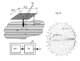
- the impedance of a known capacitive emitter with roof capacitance with inductance Lm 15 for example generating a resonance at a frequency of fo of about 1.5 GHz in the frequency band of a radio service in question, as in FIG. 4a , is therefore very unfavorable especially in the mechanical dimensions given there and the electrically small height h / ⁇ o of about 1/20.
- the mechanical instability which is accompanied by the structure of the with the roof capacity at the top mechanically loaded spotlight.
- this radiator is to be used below as a reference radiator 29.
- the (electrically small) radiator 1 for vertically polarized radio signals for a narrow bandwidth radio service by a frequency f o with the free space wavelength ⁇ o in the GHZ range comprises a substantially horizontally oriented conductor loop arranged above a conductive base surface 6 Radiator feed 5 for electromagnetic excitation of the conductor loop relative to the conductive base 6.
- the conductor loop is designed by a polygonal or elliptical / circular closed ring conductor 2 n a substantially horizontal plane with the height h smaller ⁇ o / 6 over the conductive base 6 extending.
- Distributed at the circumference of the ring conductor 2 are at least three electromagnetically coupled to conductor loop coupling points 7 and to the conductive base 6 extending towards vertical radiators 4, 4b, 4c, 4d, wherein at least two of the vertical radiator 4b, 4c and optionally 4d are electrically coupled to the electrically conductive base 6 at ground connection points 3b, 3c, 3d and a vertical radiator 4a is excited via the radiator feed 5 at its lower end.
- the vertical radiator 4b, 4c, 4d which is coupled to the electrically conductive base area 6 between its conductor loop crosspoints 7a, 7b, 7c, 7d and which are each coupled to a ground terminal 3b, 3c, 3d, and which is excited by the radiator feed point 5, between its Conductor loop coupling point 7a and the radiator feed 5 each have inductively active components 13a, 13b, 13c, 13d, so that at the radiator feed 5 at the frequency fo a low-impedance resonance is given by the character of a series resonance.
- the additional advantage that the radiator gain in flat radiation even at very low electric radiator height can be made larger by flattening the vertical directional diagram with azimuthal omnidirectional characteristics than with an elementary radiator.
- the radiator can be made as a filigree yet mechanically stable structure, which allows the combination with another vertically polarized antenna.
- a particular advantage in this case shows the possibility of an extremely economical way of producing the radiator in large numbers, which is particularly important for use in vehicles of particular importance.
- the radiator according to the invention can be designed by little complicated complementary measures for an additional wider frequency range as a circularly polarized antenna, in particular for the reception of satellite radio signals.
- a significant advantage of a radiator according to the invention is further given by the possibility that the remaining free in the center of the loop area on the base can be largely used for attaching additional combined antennas for additional other radio services.
- the ring conductor (2) may be formed by a closed wire ring and coupled to the vertical radiators by galvanic connection.
- radiator 29 in FIG. 4a consists of the radiator according to the invention in the FIGS. 1 and 4b from a ring conductor 2, on whose circumference at least three vertical radiators 4a, 4b, 4c and 4d are arranged, wherein the ring line 2 is excited via one of the vertical radiators 4a and the other vertical radiators 4b, 4c and 4d respectively via an inductance 15 are electrically conductively connected to the conductive base 6.
- the vertical radiators 4a-c and d azimuthally distributed approximately the same and the inductance 15 of all radiators are chosen approximately equal.
- the real part the impedance at the radiator feed 5 is about the square of the number N of the vertical radiator greater than a reference radiator 29 of the same geometric height h according to equation (2), so that at electrically low height h / ⁇ o and with a suitable choice of the number N of the vertical Emitter 4, the emitter impedance can be designed much closer to the target impedance ZL for impedance matching.
- Rs ZL rsm ZL * N 2 ⁇ 32 * H ⁇ ⁇ O 2 * N 2
- a comparison of the bandwidths of the impedance curves in the FIGS. 4b for the radiator according to the invention with the inductors 15 of about 25nH each and in FIG. 4a for the reference radiator 29, within the detectable accuracy, the same values for the relative bandwidth of Brel 3.6% are obtained. This is determined in each case by the frequency spacings of the impedances with + 45 ° and -45 ° phase around the resonance frequency fo -1.5 GHz.
- an antenna based on the reference radiator 29 with a matching network 35 for transforming the radiator impedance into the target impedance ZL undergoes a bandwidth reduction, which is not subject to a radiator according to the invention due to its favorable radiator impedance.
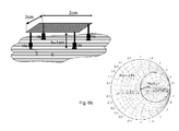
- the additional advantage that the bandwidth factor is practically independent of the conductor width 8 in FIG. 2 . If the vertical radiators 4a-d according to the invention are attached approximately to the outer boundary of the ring line 2, then the currents on the outer boundary of the ring line contribute to the formation of the radiator properties, so that the bandwidth factor of the conductor width 8 is virtually independent to the special case that the ring conductor by a closed area, as in FIG. 6b , is formed.
- the impedances of the radiators according to the invention in the FIGS. 4b . 6a and 6b show in comparison with increasing ring conductor width 8 only insignificantly changing resonance resistance Rs at the frequency fo.
- the bandwidth of the radiator according to the invention is mainly dependent on the relative radiator height, ie with (h / ⁇ o) 2 and the capacitance of the ring conductor 2 according to its outer boundary.
- it is practically independent of the ring conductor width 8 and the diameter d of a mechanically intrinsically stable wire-shaped ring conductor 2, as can be seen from a comparison of the in the FIGS. 6a and 6b specified bandwidths. This results in the significant advantage in designing an antenna for vehicles that the space in the center Z of the radiator can be provided for combination with other radiators for other radio services.
- the inventive advantage of the effortless adaptation of the impedance of the radiator according to the invention to ZL 50 ohms with respect to the reference radiator 29 with a VSWR value of more than 20 dB.
- the VSWR values of the reference radiator 29 are far greater than the resonance frequency on average by about 20 dB, so that a radiator according to the invention is much more decoupled from adjacent antennas for other radio services, such as telephone services with strong transmission radiation.
- the resonance resistance is within a large value range of h ', which is of interest for practical use.
- h / ⁇ o near the Target resistance ZL can be designed.
- the dot-dash curve for the impedance of the monopole with roofing capacity as a reference radiator 29 with the same external dimensions shows the comparison of more than an order of magnitude deviating low values.
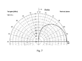
- FIG. 7 the vertical radiation pattern of a radiator according to the invention is shown with an advantageously increased gain over a prior art antenna according to the prior art and
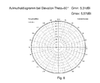
- FIG. 8 shows the azimuthal circular diagram with the azimuthal fluctuation Gmax-Gmin ⁇ 0.26 dB.
- the gain increase in the frequency environment of the resonant frequency f o is due to the spacing of the vertical radiators 4a-4c and their action as a radiator group with co-excited currents, but on the other hand causes only the above-mentioned slight azimuthal gain fluctuation at not too great a distance.
- the advantage associated with the radiator according to the invention is that the transverse extent of the ring conductor 2, which is related to the wavelength ⁇ o, is not limited to similarly small values, as is the case for its height h. This makes it possible to increase the bandwidth of the radiator at the same relative radiator height h / ⁇ o, or alternatively to reduce the height further with the same bandwidth.
- the in the FIGS. 4b . 6a and 6b given relative bandwidths Brel ⁇ 3,6% about the ratio between the length of the square boundary of the ring line 2 to the circumference of the circular loop smaller.
- the capacity of the ring conductor 2 is thus given approximately by the extended length of its outer boundary and contributes linearly to the formation of the bandwidth B of the impedance around the resonance frequency fo.
- the azimuthal radiation pattern is given even with comparatively large transverse expansions of the ring conductor 2 as a circular diagram.
- the ring conductor 2 is designed as a closed approximately wire-shaped ring, with which the vertical radiator 4 are galvanically connected.
- This ring conductor 2 with radiators 4 can be economically punched from sheet metal and produced by subsequent bending of the radiator 4.
- the conductive base in the region of the radiator 1 is designed as a printed circuit board.
- the prefabricated radiator part can be easily connected to the lower ends of the vertical radiators with the inductors 15 - for example by soldering - whereby a mechanically extremely stable radiator construction is given.
- This mechanical stability is of great advantage, in particular with regard to the narrow relative bandwidth of some radio services, which counteracts detuning due to mechanical vibrations and ensures high reproducibility in the production process.
- the ring conductor 2 in the horizontal plane surface and its outer boundary in Be designed substantially symmetrically to its center Z, wherein the inner boundary of the ring conductor 2 inner is designed in such a way that along the circumference of the ring conductor width B is smaller than 1/4 of the measured over the center Z horizontal extension of the ring conductor.
- the space around the center Z of the ring conductor 2 is advantageously available for the exemplary design of further antennas.
- the similarity of the currents in the vertical radiators 4 is important for the resulting optimal support of the vertically polarized radiation.
- This is particularly advantageous to achieve when the ring conductor 2 is circular or designed as a regular polygon with N corners and over the circumference L of the circle or at the corners of the N-corner over the circumference of the length L of the ring conductor 2 in number N mutually identical vertical radiators 4a-d in the same length elongated lengths L / N of the structure away from each other via the conductor loop coupling points 7a-d to the ring conductor 2 are galvanically coupled 6.
- the resonance at the frequency fo is brought about by designing the inductively active components 13a-d of the vertical radiators 4a-d.
- the vertical radiators 4a-d can likewise be connected in each case at an interruption point with an inductance 15a-d of the inductive components 13a-d necessary for this purpose.
- the components 13a-d inductively active in the vertical radiators 4b-d have approximately the same size in all vertical radiators 4a-d, so that-as already stated above-at resonance in these radiators 4a-d flow equal direction currents of about the same size.
- this condition is not necessarily met meticulously for a basic perception of the advantages achieved by the invention in terms of a favorable radiator impedance.
- optimum conditions can be achieved with regard to the radiator impedance and the azimuthal directional independence of the directional diagram.
- the choice of an interruption point for switching on concentrated inductive components is carried out for the production of the radiator 1 particularly low at the lower end of a rod-shaped vertical radiator 4a-d.
- the other terminal of the radiator feed 5 is formed on the conductive base 6.
- the inductors 15a-d can advantageously be designed as printed inductances 32a-d on the electrically conductive base 6 designed as an electrically conductive printed circuit board, each at one end with the vertical radiator 4a-d and at the other End are connected to the electrically conductive base 6 and also designed on the coated circuit board a connection of the radiator feed 5.
- the inductors 32a-d can be omitted if the inductively active components 13a-13d are each realized by shaping the vertical radiators 20.
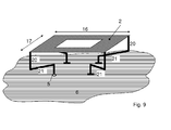
- vertical radiator parts 20 and horizontally extending radiator parts 21 are formed, so that the in FIG. 1 shown necessary inductive components 13a - 13c are achieved even at a small height h.
- the design of the vertical radiator parts 20 and the horizontally extending radiator parts 21 in FIG. 9 also combined by oblique radiator parts 22, as in FIG. 10 represented, or carried by meandering radiator parts.
- a radiator 1 with such vertical radiators 4a-c can be produced, for example, economically from a piece punched from sheet metal and subsequent bending, and the vertical radiators are connected at their lower end to the conductive base 6 or to the radiator junction 5 formed there.
- a particularly economical solution for use in vehicles is to be achieved by choosing the appropriate dimensions of the radiator 1 in such a way that at the radiator feed 5 adaptation to ZL without matching network 35 is given and the radiator feed 5 -.
- the antenna connection point 34 forms an antenna 36 adapted to ZL.
- the impedance matching to ZL can be effected simply by selecting the resonant frequency fo in such a way that the slight detuning of the resonance of the radiator between the radiator feed point 5 occurs at a slightly higher frequency f in the frequency band of the radio service and the adjacent ground terminal 3a occurring impedance is inductive.
- impedance matching to ZL can be achieved in a simple manner, whereby the radiator feed point 5 likewise forms the antenna connection point 34 of an antenna 36 adapted to ZL.
- the ring conductor 2 is designed as a square, at the corners of each a ring line crosspoint 7 with a galvanically connected there vertical radiator 4, 4a-d is formed.
- Three of the radiators 4, 4b-d are connected to the electrically conductive base 6 for coupling to a ground terminal 3b-d via an inductor 13b-d to the ground terminal 3b-d and a radiator 4, 4a, optionally over an inductor 13a connected to the radiator feed 5.
- the resonance frequency fo is approximately equal to the center frequency f of the service and the pages of The squares are approximately equal to ⁇ o / 10 and the heights h, 9 are approximately equal to ⁇ o / 20.
- a radiator with these external dimensions can advantageously be designed in such a way that there is impedance matching at ZL at the radiator feed point 5 and thus the antenna connection point 34 is provided by the latter.
- a radiator according to the invention advantageously offers the possibility of sunk the radiator and to integrate without significant loss of its radiation properties in the vehicle body.
- the ring conductor 2 in a further horizontal loop level E in height h, 9 extending over the cavity base surface 6a introduced in such a manner that the conductive cavity base surface 6a, the projection surface of the ring conductor 2 at the lying below the conductive surface plane E1 base surface plane E2 at least covers and the cavity side surfaces 40 at each point a contour in have the way that a sufficiently large cavity spacing 10 between the ring conductor 2 and the cavity 38 is given at each point.
- a sinking of the radiation resistance Rs is associated with the recessed installation of a radiator.
- the increase of the radiation resistance by a factor N 2 according to the invention relative to a reference radiator 29 is of particular importance.
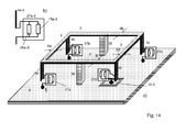
- the emitter 1 which is designed for vertical polarization for a radio service to the frequency fo, extended in its function for the reception of circularly polarized satellite radio signals of a satellite service at a frequency fs> fo, as exemplified in Fig. 14 is shown.
- the phases of the currents in these radiators are adjusted in such a way that the ring conductor 2 is operated together with the conductive base 6 as a loop, so that at the frequency fs a resonant structure is formed in such a way that is adjusted by feeding via one of the vertical radiator 4d with radiator feed 5 on the loop the current distribution of a current line wave in a single direction of rotation, the phase difference over an azimuthal cycle is just 2 ⁇ ,
- the supply of the radiator for the function of the circular polarization can also be done at the radiator feed point 5 in an advantageous manner.
- a radiator for the reception of circularly polarized satellite signals is known from DE 10 2009 040 910
- the feed is given to a vertical radiator via a capacitance and the connection of the other radiator to the electrically conductive base surface 6 also over capacity.
- Is the inductors 15a-d of the coupled to the conductive ground plane vertical radiator 4a-c and the one vertical radiator 4d with radiator feed 5 each have a capacitive element 26a-d connected in parallel.
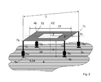
- the space which can be designed in the center of the ring conductor 2 is used for attaching a further vertically polarized antenna, as shown by way of example in FIG 15A is shown with a rod-shaped antenna 28.
- a vertical substantially rod-shaped antenna for at least one further radio service can advantageously be designed along a vertical center line VZ.
- the frequency-selective dipoles 25 are low impedance in the frequency ranges of the other radio services and in the frequency range which is associated with the radiator 1 with ring conductor 2, high-impedance perform.
- the design of rod-shaped, radiation-isolated antennas bridged by frequency-selectively bridged interruption points is known from the DE103 04 911 ,
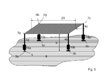
- the ring conductor 2 can essentially be defined by the boundary of a closed conductive surface, as in FIG Fig. 3 , the ring line coupling points 7a, 7b, 7c, 7d are each formed in the vicinity of this boundary.
- the electrical properties such. As the radiation resistance Rs at the resonant frequency fo, are only insignificantly influenced by the representation of the ring conductor 2 as a closed surface due to the essential for the function currents along the boundary of the surface. This also applies to the relative radiator bandwidth Brel.
- the bandwidth B can theoretically by a factor of 2 ⁇ / In2 be increased by additions to a matching network at the antenna connection point 34 assuming an arbitrarily complicated, but lossless matching network, as cited in the cited document in the AEÜ is.
- the magnification factors that can be achieved in practice are all the smaller, with reasonable economic outlay, the further the radiator impedance deviates from the target impedance ZL.
- losses increase the bandwidth, but to the same extent reduce the radiation gain of an antenna.
- the radiator 1 according to the invention is always superior to the reference radiator 29 with matching network even when supplementing with a matching network and taking into account losses in terms of radiation gain and achievable bandwidth.
Landscapes
- Details Of Aerials (AREA)
- Waveguide Aerials (AREA)
- Variable-Direction Aerials And Aerial Arrays (AREA)
Abstract
Description
Die Erfindung betrifft einen elektrischen Strahler für vertikal polarisierte Funksignale für einen Funkdienst mit schmaler Frequenzbandbreite um eine Frequenz fo mit der Freiraum-Wellenlänge λo im GHZ-Bereich für die bevorzugte Verwendung auf Fahrzeugen.The invention relates to an electric radiator for vertically polarized radio signals for a radio service with a narrow frequency bandwidth around a frequency fo with the free space wavelength λo in the GHZ range for the preferred use on vehicles.
Bedingt durch die Vielzahl der Funkdienste, deren Verfügbarkeit im Fahrzeug unabdingbar geworden ist, kommt es bei der Gestaltung von Antennen insbesondere auf kleines Bauvolumen in Verbindung mit möglichst kleiner Höhe an. Vielfach ist es bei guter Antennenleistung nicht möglich und nicht zweckmäßig, eine Anzahl in jeweils relativ schmalen, jedoch in der Frequenz relativ weit voneinander liegenden Frequenzbereichen operierenden Funkdiensten mit einer breitbandig arbeitenden Antenne abzudecken. Vielfach werden die Funksignale der verschiedenen Funkdienste auch mit unterschiedlicher Polarisation ausgestrahlt, so dass es nicht zweckmäßig ist, den verschiedenen Anforderungen mit einer Antenne gerecht zu werden. Vielmehr kommt es für Fahrzeugantennen darauf an, für die einzelnen Funkdienste Antennen mit filigranen Strukturen zu schaffen, welche insbesondere bei immer möglichst kleiner Höhe und häufig bei kleiner Grundfläche mit Antennen für andere Funkdienste kombiniert werden können, um in der Gesamtheit Kombinationsantennen mit kleinem Raumbedarf zu gestalten. Solche Kombinationsantennen werden gegebenenfalls mit einer Plastikhülle als Radom abgedeckt oder gar vertieft in eine Ausformung der Karosserie als Kavität eingebracht. Zusätzlich wird an die Konstruktion von Fahrzeugantennen ein hoher Anspruch an deren mechanische Stabilität und Erschütterungsfestigkeit gestellt. Die beispielhafte Betrachtung von nur einigen Antennen der vielfach für das Fahrzeug geforderten Funkdienste im Dezimeter-Wellenbereich, wie Antennen für die Mobilfunkdienste GSM und den in der Frequenzbandbreite schmalen digitalen Rundfunkdienst im L-Band bei ca. 1,5 GHz mit jeweils mit vertikaler Polarisation ausgestrahlten Funksignalen sowie den schmalbandigen digitalen Satelliten-Rundfunkdienst SDARS bei ca. 2,3 GHz , dessen Signale in zirkularer Polarisation vom Satelliten ausgestrahlt werden, lässt erkennen, dass die Schaffung einer einzelnen Breitbandantenne zur Abdeckung aller Funkdienstezu zu schier unüberwindlichen Schwierigkeiten führen würde. Zusätzlich ist für den Empfang aller genannten Funkdienste aufgrund der in Großserie hergestellten Antennen die Wirtschaftlichkeit bei der Herstellung von ausschlaggebender Bedeutung.Due to the large number of radio services, the availability of which has become indispensable in the vehicle, in the design of antennas it is particularly important to have a small construction volume in conjunction with the smallest possible height. In many cases it is not possible with good antenna performance and not appropriate to cover a number in each case relatively narrow, but in the frequency relatively widely spaced frequency ranges operating radio services with a broadband antenna. In many cases, the radio signals of the various radio services are also broadcast with different polarization, so that it is not appropriate to meet the various requirements with an antenna. Rather, it is important for vehicle antennas to create antennas with filigree structures for the individual radio services, which can be combined with antennas for other radio services, in particular with the smallest possible height and often with a small footprint, in order to design combination antennas with a small space requirement as a whole , Such combination antennas are optionally covered with a plastic sheath as Radom or even deepened introduced into a molding of the body as a cavity. In addition, the design of vehicle antennas has a high demand on their mechanical stability and vibration resistance. The exemplary consideration of only a few antennas of the radio frequency services required in the decimetre waveguide, such as antennas for the GSM mobile services and the narrow band in the L-band digital broadcasting service at about 1.5 GHz, each with vertical polarization radiated Radio signals and the SDARS narrowband digital satellite broadcasting service at approximately 2.3 GHz, whose signals are broadcast in circular polarization from the satellite, indicate that the creation of a single broadband antenna to cover all radio services would lead to insurmountable difficulties. In addition, for the reception of all the above-mentioned radio services due to the mass-produced antennas, the profitability in the production of crucial importance.
Für den Mobilfunkdienst GSM werden seit langem vertikale Strahler eingesetzt, wie sie zum Beispiel in der 
mit Zo = 120π Ohm = Feldwellenwiderstand des freien Raums und der Lichtgeschwindigkeit co.For the mobile service GSM long since vertical emitters are used, as for example in the
with Zo = 120π ohm = field wave resistance of free space and the speed of light co.
Die ausschlaggebenden mechanischen Abmessungen der Antenne sind für die hier durchgeführten Betrachtungen ausschließlich in dem Ausdruck für den Bandbreitenfaktor BFm in Klammern enthalten, wobei bei hinreichend großer Dachkapazität Cs die effektive Höhe hem des Monopolstrahlers seiner geometrischen Höhe h gleichkommt. Für die Erfüllung der relativen Bandbreite eines elektrisch kurzen Strahlers für einen bestimmten Funkdienst mit der Mittenfrequenz fo kann somit der Term außerhalb des Klammerausdrucks "Bandbreitenfaktor" = BFm für den Monopol zu einer von seinen Abmessungen unabhängigen Konstanten k zusammengefasst werden. Diese Strahlerbandbreite stellt im Folgenden die Referenzbandbreite dar. Im Impedanz-Diagramm in 
Bezüglich des Einsatzes eines derartigen Resonanzstrahlers 29 in
Aufgabe der Erfindung ist es deshalb, einen Strahler nach dem Oberbegriff des Anspruchs 1 zu schaffen, welcher auch bei sehr kleiner elektrischer Höhe h/λo und bei mechanischer Stabilität in der Frequenzumgebung seiner Resonanzfrequenz fo eine Impedanz in der Nähe des für Funksysteme in Fahrzeugen vorgeschriebenen und normierten Widerstands ZL = 50 Ohm besitzt, so dass der technische Aufwand zur Ergänzung des Strahlers durch ein Anpassnetzwerk für Anpassung an ZL = 50 Ohm zu einer Antenne über eine relativ große Frequenzbandbreite wirtschaftlich gestaltet werden kann.The object of the invention is therefore to provide a radiator according to the preamble of
Diese Aufgabe wird bei einer Antenne nach dem Oberbegriff des Hauptanspruchs durch die kennzeichnenden Merkmale des Hauptanspruchs gelöst.This object is achieved in an antenna according to the preamble of the main claim by the characterizing features of the main claim.
Gemäß der Erfindung umfasst der (elektrisch kleine) Strahler 1 für vertikal polarisierte Funksignale für einen Funkdienst mit schmaler Frequenzbandbreite um eine Frequenz fo mit der Freiraum-Wellenlänge λo im GHZ-Bereich eine im Wesentlichen horizontal orientierte, über einer leitenden Grundfläche 6 angeordnete Leiterschleife mit einer Strahlerspeisestelle 5 zur elektromagnetischen Erregung der Leiterschleife gegenüber der leitenden Grundfläche 6. Die Leiterschleife ist durch einen polygonartig oder elliptisch/kreisförmig geschlossenen Ringleiter 2 n einer im Wesentlichen horizontalen Ebene mit der Höhe h kleiner λo/6 über der leitenden Grundfläche 6 verlaufend gestaltet. Am Umfang des Ringleiters 2 verteilt sind mindestens drei an Leiterschleifen-Koppelpunkten 7 mit dem Ringleiter 2 elektromagnetisch verkoppelte und zur leitenden Grundfläche 6 hin verlaufende vertikale Strahler 4, 4b, 4c, 4d vorhanden, wobei mindestens zwei der vertikalen Strahler 4b, 4c und gegebenenfalls 4d mit der elektrisch leitenden Grundfläche 6 an Masse-Anschlusspunkten 3b, 3c, 3d elektromagnetisch verkoppelt sind und ein vertikaler Strahler 4a über die Strahlerspeisestelle 5 an dessen unterem Ende erregt ist. Die mit der elektrisch leitenden Grundfläche 6 zwischen ihren Leiterschleifen-Koppelpunkten 7a, 7b, 7c, 7d und dem jeweils mit einem Masse-Anschlusspunkt 3b, 3c, 3d verkoppelten vertikalen Strahler 4b, 4c, 4d und der über die Strahlerspeisestelle 5 erregte, zwischen seinem Leiterschleifen-Koppelpunkt 7a und der Strahlerspeisestelle 5 besitzen jeweils induktiv wirksame Komponenten 13a, 13b, 13c, 13d, so dass an der Strahlerspeisestelle 5 bei der Frequenz fo eine niederohmige Resonanz vom Charakter einer Serienresonanz gegeben ist.According to the invention, the (electrically small)
Mit einem Strahler nach der Erfindung ist der zusätzliche Vorteil verbunden, dass der Strahlergewinn bei Flachstrahlung auch bei sehr niedriger elektrischer Strahlerhöhe durch Abflachung des vertikalen Richtdiagramms bei azimutaler Rundcharakteristik größer gestaltet werden kann als mit einem Elementarstrahler. Weiterhin kann der Strahler als filigrane und dennoch mechanisch stabile Struktur hergestellt werden, welche die Kombination mit einer weiteren vertikal polarisierten Antenne zulässt. Als besonderer Vorteil zeigt sich hierbei die Möglichkeit einer äußerst wirtschaftlichen Weise der Herstellung des Strahlers in großen Stückzahlen, welche insbesondere für den Einsatz in Fahrzeugen von besonderer Bedeutung ist. Weiterhin kann der erfindungsgemäße Strahler durch wenig komplizierte ergänzende Maßnahmen für einen zusätzlichen weiteren Frequenzbereich als zirkular polarisierte Antenne insbesondere für den Empfang von Satellitenfunksignalen gestaltet werden. Ein wesentlicher Vorteil eines Strahlers nach der Erfindung ist ferner durch die Möglichkeit gegeben, dass der im Zentrum der Ringleitung frei bleibende Bereich auf der Grundfläche weitgehend zur Anbringung weiterer kombinierter Antennen für zusätzliche andere Funkdienste genützt werden kann.With a radiator according to the invention, the additional advantage that the radiator gain in flat radiation even at very low electric radiator height can be made larger by flattening the vertical directional diagram with azimuthal omnidirectional characteristics than with an elementary radiator. Furthermore, the radiator can be made as a filigree yet mechanically stable structure, which allows the combination with another vertically polarized antenna. A particular advantage in this case shows the possibility of an extremely economical way of producing the radiator in large numbers, which is particularly important for use in vehicles of particular importance. Furthermore, the radiator according to the invention can be designed by little complicated complementary measures for an additional wider frequency range as a circularly polarized antenna, in particular for the reception of satellite radio signals. A significant advantage of a radiator according to the invention is further given by the possibility that the remaining free in the center of the loop area on the base can be largely used for attaching additional combined antennas for additional other radio services.
Nach einer vorteilhaften Ausführungsform kann der Ringleiter (2) durch einen geschlossenen Drahtring gebildet sein und mit den vertikalen Strahlern durch galvanische Verbindung verkoppelt sein.According to an advantageous embodiment, the ring conductor (2) may be formed by a closed wire ring and coupled to the vertical radiators by galvanic connection.
Die Erfindung wird im Folgenden anhand von Ausführungsbeispielen näher erläutert. Die zugehörigen Figuren zeigen im Einzelnen:
-
Fig. 1 :
Strahler 1 nach der Erfindung mit kreisförmigem, zum Beispieldrahtförmigem Ringleiter 2 in der Höhe h über einerleitenden Grundfläche 6 verlaufend, mit N= 3 an Ringleitungs-Koppelpunkten vertikalen Strahlern vertikale Strahler Anschlusspunkte 3b 3c mit derleitenden Grundfläche 6 verbunden sind und am unteren Ende eines dervertikalen Strahler 4a dieStrahlerspeisestelle 5 gebildet ist, über welche derStrahler 1 erregt ist. Alle vertikalen Strahler 4a, 4b, 4c besitzen induktivwirksame Komponenten -
Fig. 2 :
Strahler nach der Erfindung wie inFigur 1gestaltetem Ringleiter 2 und größerer Leiterbreite 8 und mit N = 4 Ringleitungs-Koppelpunkten vertikalen Strahlern -
Fig. 3 :
Strahler nach der Erfindung wie inFigur 2Ringleiters 2 derart gewählt ist, dass innerhalb der äußeren Berandung desRingleiters 2 eine geschlossene, leitende Fläche gebildet ist. -
Fig. 4a undFig. 4b
Gegenüberstellung der Impedanzverläufe eines Strahlers mitquadratischem Ringleiter 2 nach der Erfindung gemäßFig. 4b und eines Stabmonopols mit quadratischer Dachkapazität und Fußpunktinduktivität Lm 15 alsReferenzstrahler 29 gemäßFig.4a in der komplexen, auf ZL bezogenen Impedanzebene jeweils in der Frequenznähe der Resonanzfrequenz fo = 1.4 GHz bei gleicher Höhe h = 1cm undgleicher Kantenlänge 23 von 2cm der quadratischen Dachkapazität desReferenzstrahlers 29 und des quadratischgestalteten Ringleiters 2 mit der Leiterbreite 8 von 2mm desStrahlers 1 nach der Erfindung. Die einander gleichen äußeren Abmessungen der beidenStrahler 1 und 29 bedingen zunächst gleiche relative Strahlerbandbreiten von Brel = 3,6%. Die mit dem extrem niedrigen Resonanzwiderstand Rsm/ZL = 0,06 gemäßFig. 4a verbundene Schwierigkeit der Anpassung der Strahlerimpedanz an ZL bedingt jedoch einen großen technischen Aufwand und eine Reduzierung der wirksamen relativen Bandbreite des durch einAnpassnetzwerk 35 ergänzten Strahlers. Das Verdienst der vorliegenden Erfindung ist es, dass diese Nachteile bei einem Strahler nach der Erfindung mit Rs/ZL = 0,85 gemäßFig. 4b in der Praxis entfallen können. -
Fig. 5 :
Verlauf des auf ZL bezogenen Strahlungswiderstands bei der Resonanzfrequenz fo in Abhängigkeit von der relativen geometrischen Strahlerhöhe h/λo = h' des Referenzstrahlers 29 (strichpunktiert) und desStrahlers 1 nach der Erfindung (N = 4) inFigur 4bStrahler 1 nach der Erfindung mit jeweils einem als reguläres Dreieck, reguläres Viereck oder Fünfeckgestalteten Ringleiter 2 mit gleicher relativer Strahlerbandbreite Brel. Der dargestellte Bereich für h' > 0,025 (sh. Marker) kennzeichnet den nutzbaren Wertebereich für h', wenn dieForderung -
Fig. 6 :
Impedanzverläufe von Strahlern nach der Erfindung mit äußeren Abmessungen wie inFigur 4bvon 5 mm inFigur 6a und der Besonderheit inFigur 6b , dass die Breite desRingleiters 2 derart gewählt ist, dass innerhalb der äußeren Berandung desRingleiters 2 eine geschlossene Fläche gebildet ist. Ein Vergleich der Impedanzverläufe in denFiguren 6a und6b zeigt, dass der Widerstand Rs/ZL bei der Resonanzfrequenz fo durch den Gestaltungsunterschied der Strahler nur wenig beeinflusst ist. Ferner zeigt sich, dass sich die relative Bandbreiten Brel = 3,6% der beiden Strahler in denFiguren 6a bzw. 6b im Rahmen der Nachweisbarkeit in der Praxis nicht unterscheiden. Der äußerst geringfügig unterschiedlichen Wirkung der unterschiedlichen Ringleiter 2 ist durch geringfügigen Nachabgleich der Induktivitäten 15a, 15b, 15c, 15d Rechnung getragen. -
Fig. 7 : zeigt das vertikale Richtdiagramm in dB-Eichung eines Strahlers nach der Erfindung mit einer gegenüber einem elektrisch kleinen Elementarstrahler (4,77dBi) erhöhtenRichtwirkung von 5,57dBi bzw. 5,31dBi durch die voneinander beabstandeten vertikalenStrahler 4a-d. -
Fig. 8 :
Azimutales Richtdiagramm für Flachstrahlung des inFigur 7 besprochenen Strahlers mit nur geringfügiger Abweichung vom Runddiagrammmit Schwankungen zwischen 5,57dBi und 5,31dBi.Fig. 9 : - Beispielhafte Realisierung eines Strahles nach der Erfindung
mit rechteckförmigem Ringleiter 2mit äußerer Querabmessung 16 und äußerer Längsabmessung 17 und
Gestaltung der vertikalen Strahler in der Weise, dass die für Resonanz notwendigen induktiv wirksamen Komponenten 13a -13d in den einzelnen Strahlern jeweils durch Formung vertikaler Strahlerteile 20 und horizontaler Strahlerteiler 21 gegeben sind. Durch Wahl entsprechender Abmessungen kann ander Strahlerspeisestelle 5 Anpassung an ZL ohne weitere Anpassungselemente erzielt werden, sodass durch dieStrahlerspeisestelle 5die Antennenanschlussstelle 24 gegeben ist. -
Fig. 10 :
Beispiel wie inFigur 9Strahler -
Fig. 11 :
Strahler nach der Erfindung in einer ausreichenden Kavitätstiefe 12, welche durch Ausformung der leitenden Grundfläche 6 gestaltet ist, so dass der Strahler zum Beispiel ohne Erhebung über die Karosseriefläche in die Fahrzeugkarosserie integriert ist. Die Basisfläche 39der Kavität 38 ist im Beispiel als gedruckte Leiterplatte gestaltet und die induktiv wirksamen Komponenten 13a -13d sind als gedruckte Induktivitäten 32a, 32b, 32c, 32d realisiert. -
Fig. 12 :
vergleichende Darstellung der auf ZL bezogenen Impedanzverläufe eines Strahlers mit kreisförmiger Ringleitung und vier vertikalen Strahlern nach der Erfindung in Kurve a) und eines Monopols mitDachkapazität als Referenzstrahler 29 in Kurve b), jeweils im Frequenzbereich zwischen 100 MHz und 2 GHz und gleichen Resonanzfrequenzen fo = 1,54 GHz. Der unterschiedliche Charakter der beiden Strahler ist in ihrem Verhalten bei niedrigen Frequenzen begründet, wobei die Impedanz in Kurve a) dort induktiv ist und deren Realteil mit f4 wächst und die Impedanz in Kurve b) dort kapazitiv ist und deren Realteil langsamer, d.h. mit f2, ansteigt. -
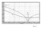
Fig. 13 :
Nachweis der vorteilhaften Frequenzselektivität der Antenne nach der Erfindung gemäß dem Impedanzverlauf a) inFigur 12Figur 12Figur 12Referenzstrahlers 29 im Nutzbereich um fo ungünstig groß und bei weitab liegenden Frequenzen ungünstig klein. -
Fig. 14 :
Beispiel eines Strahlers nach der Erfindung in Kombination mit einer Antenne für den Empfang zirkular polarisierter Satelliten-Funksignale auf einer höheren Frequenz fs als für den Funkdienst mit vertikaler Polarisation. Im Beispiel ist am unteren Ende der vertikalenStrahler 4 jeweils anstelle der gedruckten Induktivität 32a, 32b, 32c, 32d inFigur 11Schaltung 27a-d gegeben ist.Der Ringleiter 2 bildet bei der höheren Frequenz fs eine durch die kapazitive Wirkung der Blindelement-Schaltung 27 bedingte, in Resonanz befindliche Ringleitung mit Ausbildung einer umlaufenden Welle auf dieser Leitung, sodass zirkulare Polarisation bei dieser Frequenz fs gegeben ist. -
Fig. 15 :
a) zeigt die vorteilhafte Kombination eines Strahlers mit nicht zu breitem Ringleiter 2 nach der Erfindung mit einem imWesentlichen stabförmigen Strahler 28 im ZentrumZ des Ringleiters 2 für einen weiteren Funkdienst bzw. mehrere weitere Funkdienste mit vertikaler Polarisation auf anderen Frequenzen als fo. Zur Vermeidung von Strahlungskopplung zwischen den beiden Strahlern ist der stabförmigeStrahler 28 inLeiterstücke 24 unterteilt, deren elektrische Länge nicht größerist als 3/8*λo. b) die Unterbrechungsstellen sind durch frequenzselektive Zweipole 25 überbrückt, welche bei der Frequenz fo hochohmig und in den Frequenzbereichen der anderen Funkdienste niederohmig sind.
-
Fig. 1 :
Emitter 1 according to the invention with a circular, for example, wire-shapedring conductor 2 in height h over aconductive base 6 extending, with N = 3 atring line crosspoints vertical radiators vertical radiators ground 3c to theconnection points 3bconductive base 6 and at the lower end of one of thevertical radiators 4a, theradiator feed 5 is formed, via which theradiator 1 is energized. All thevertical radiators effective components -
Fig. 2 :
Emitter according to the invention as inFIG. 1 However, with square or rectangular, for example, surface designedring conductor 2 and 8 larger conductor width and with N = 4loop coupling points vertical radiators -
Fig. 3 :
Emitter according to the invention as inFIG. 2 , However, with the special feature that the width of thering conductor 2 is selected such that within the outer boundary of thering conductor 2, a closed, conductive surface is formed. -
Fig. 4a andFig. 4b
Comparison of the impedance curves of a radiator withsquare ring conductor 2 according to the invention according toFig. 4b and a rod monopole with square roof capacitance and basepoint inductance Lm 15 as thereference radiator 29 according to FIG4a in the complex, on ZL-related impedance level in each case near the frequency of the resonant frequency fo = 1.4 GHz at the same height h = 1cm and thesame edge length 23 of 2cm of the square roof capacity of thereference radiator 29 and the square shapedring conductor 2 with the conductor width 8 of 2mm of theradiator 1 according to the invention. The same outer dimensions of the tworadiators Fig. 4a However, the associated difficulty of matching the emitter impedance to ZL requires a great deal of technical effort and a reduction in the effective relative bandwidth of the emitter complemented by amatching network 35. The merit of the present invention is that these disadvantages in a radiator according to the invention with Rs / ZL = 0.85 according toFig. 4b can be omitted in practice. -
Fig. 5 :
Course of the relative to ZL radiation resistance at the resonant frequency fo as a function of the relative geometric radiator height h / λo = h 'of the reference radiator 29 (dash-dotted lines) and theradiator 1 according to the invention (N = 4) inFIG. 4b , The curves N = 3, N = 4 or N = 5 refer toradiator 1 after the Invention with one designed as a regular triangle, regular square orpentagon ring conductor 2 with the same relative radiator band width Brel. The range shown for h '> 0.025 (see marker) identifies the usable value range for h' if the requirement 0.5 <Rs / ZL <2 (see borderlines) is to be met by way of example. -
Fig. 6 :
Impedance curves of radiators according to the invention with external dimensions as inFIG. 4b , but with a conductor width 8 of 5 mm inFIG. 6a and the peculiarity inFIG. 6b in that the width of thering conductor 2 is chosen such that a closed surface is formed within the outer boundary of thering conductor 2. A comparison of the impedance curves in theFIGS. 6a and6b shows that the resistance Rs / ZL at the resonant frequency fo is only slightly affected by the design difference of the radiators. Furthermore, it can be seen that the relative bandwidths Brel = 3.6% of the two radiators in theFIGS. 6a or 6b in the context of verifiability in practice. The extremely slight difference in the effect of thedifferent ring conductors 2 is taken into account by slight rebalancing of theinductances -
Fig. 7 Figure 12 shows the vertical directional diagram in dB calibration of a radiator according to the invention with a 5.57dBi and 5.31dBi directivity, respectively, enhanced by a 5.7dBi and 5.31dBi versus a small electric elementary radiator (4.77dBi) by the spaced-apartvertical radiators 4a-d. -
Fig. 8 :
Azimuthal directional diagram for flat radiation of inFIG. 7 discussed spotlight with only slight deviation from the circular diagram with variations between 5.57dBi and 5.31 dBi.Fig. 9 : - Exemplary realization of a beam according to the invention with
rectangular ring conductor 2 with outertransverse dimension 16 and outerlongitudinal dimension 17 and
Design of the vertical radiator in such a way that the necessary for resonance inductivelyeffective components 13a -13d in the individual radiators respectively Formingvertical radiator parts 20 andhorizontal beam splitter 21 are given. By choosing the appropriate dimensions, adaptation to ZL can be achieved at theradiator feed point 5 without further adaptation elements, so that theantenna connection point 24 is provided by theradiator feed point 5. -
Fig. 10 :
Example as inFIG. 9 but withoblique beam parts 22 of thevertical radiators -
Fig. 11 :
Emitter according to the invention in asufficient cavity depth 12, which is designed by shaping theconductive base 6, so that the radiator is integrated, for example, without elevation over the body surface in the vehicle body. The base surface 39 of thecavity 38 is designed in the example as a printed circuit board and the inductivelyactive components 13a -13d are realized as printedinductors -
Fig. 12 :
Comparative representation of the ZL related impedance curves of a radiator with circular loop and four vertical radiators according to the invention in curve a) and a monopole with roof capacity as areference radiator 29 in curve b), respectively in the frequency range between 100 MHz and 2 GHz and the same resonant frequencies fo = 1.54 GHz. The different character of the two emitters is due to their behavior at low frequencies, the impedance in curve a) is there inductive and their real part with f 4 grows and the impedance in curve b) is capacitive there and the real part slower, ie with f 2 , increases. -
Fig. 13 :
Detection of the advantageous frequency selectivity of the antenna according to the invention in accordance with the impedance curve a) in FIGFIG. 12 based on the frequency curve of the VSWR, based on the resistance ZL according to curve a) inFIG. 12 with very low values in the frequency domain with the useful bandwidth B around the resonant frequency fo and extremely favorable high values of the VSWR at frequencies which differ far from fo. In contrast, the values of the VSWR are according to the Impedance curve b) inFIG. 12 of thereference radiator 29 in the useful range to fo unfavorably large and unfavorably small at far frequencies. -
Fig. 14 :
Example of a radiator according to the invention in combination with an antenna for receiving circularly polarized satellite radio signals at a higher frequency fs than for the vertical polarization service. In the example, at the lower end of thevertical radiator 4 respectively in place of the printedinductance FIG. 11 a frequency-selective dipole designed, for example, each of the parallel circuit of a capacitive element 26 and aninductance dummy element Circuit 27a-d is given. Thering conductor 2 forms at the higher frequency fs due to the capacitive effect of the dummy element circuit 27, resonant ring line with the formation of a rotating wave on this line, so that circular polarization is given at this frequency fs. -
Fig. 15 :
a) shows the advantageous combination of a radiator with not toowide ring conductor 2 according to the invention with a substantially rod-shapedradiator 28 in the center Z of thering conductor 2 for another service or several other radio services with vertical polarization at frequencies other than fo. To avoid radiation coupling between the two radiators, the rod-shapedradiator 28 is divided intoconductor pieces 24 whose electrical length is not greater than 3/8 * λo. b) the interruption points are bridged by frequency-selective two-pole 25, which are high-impedance at the frequency fo and low in the frequency ranges of the other radio services.
Die Beschreibung der Wirkungsweise eines Strahlers nach der Erfindung kann anschaulich anhand eines Vergleichs mit dem bereits oben genannten elektrisch kleinen als Referenzstrahler 29 bezeichneten Monopol-Stabstrahler in
Im Gegensatz zum Referenzstrahler 29 in 
Hierbei zeigt sich als besonderer Vorteil eines Strahlers nach der Erfindung, dass die Bandbreite seines Impedanzverlaufs nicht kleiner ist als die eines Referenzstrahlers 29 mit gleichen äußeren Abmessungen der Dachkapazität 11 bzw. des Ringleiters 2 in den
Wie bereits weiter oben ausgeführt, erfährt jedoch eine Antenne auf Basis des Referenzstrahlers 29 mit einem Anpassnetzwerk 35 zur Transformation der Strahlerimpedanz in die Zielimpedanz ZL eine Bandbreitenreduktion, welcher ein Strahler nach der Erfindung aufgrund seiner günstigen Strahlerimpedanz nicht unterworfen ist. Zudem ergibt sich bei einem Strahler nach der Erfindung der zusätzliche Vorteil, dass der Bandbreitenfaktor praktisch unabhängig ist von der Leiterbreite 8 in
Insbesondere für die Gestaltung von Kombinationsantennen für mehrere Funkdienste auf engem Raum auf Fahrzeugen ist die Frequenzselektivität eines Strahlers 1 nach der Erfindung von besonderem Vorteil. Dies geht anschaulich aus der Gegenüberstellung des Frequenzverlaufs der VSWR-Werte eines Strahlers 1 nach der Erfindung mit Resonanzfrequenz fo = 1,53 Gigahertz in
Wie bereits oben im Zusammenhang mit
In
Wenngleich auch die Anforderung an eine kleine geometrische Antennenhöhe h eine der Hauptaufgaben für die Gestaltung einer Fahrzeugantenne darstellt und insbesondere für Antennen, welche im Frequenzbereich um 1,5 GHz, wie zum Beispiel für den DAB-Rundfunkdienst im L-Frequenzband, eine Antennenhöhe von h = 1 cm, das heißt h/λo = 1/20, gefordert ist, so ist die Ausdehnung der Ringleitung 2 nicht grundsätzlich auf ähnlich kleine Werte eingeschränkt. Mit dem Strahler nach der Erfindung ist somit der Vorteil verbunden, dass die auf die Wellenlänge λo bezogene Querausdehnung des Ringleiters 2 nicht auf ähnlich kleine Werte beschränkt ist, wie dies für seine Höhe h der Fall ist. Dadurch ist es möglich, die Bandbreite des Strahlers bei gleicher relativer Strahlerhöhe h/λo zu vergrößern, oder alternativ bei gleicher Bandbreite die Höhe weiter zu reduzieren. Zur Veranschaulichung kann das Beispiel eines Strahlers nach der Erfindung mit einer kreisförmigen Ringleitung 2 wie in
In vorteilhafter Weise ist das azimutale Strahlungsdiagramm auch bei vergleichsweise großen Querausdehnungen des Ringleiters 2 als Runddiagramm gegeben. Bei dem oben genannten Beispiel einer Antenne mit kreisförmigem Ringleiter und dem relativen Durchmesser von D/λo = 0,32 beträgt die gestreckte Länge eines Ringleiter-Abschnitts zwischen zwei einander benachbarten Ringleitungs-Koppelpunkten 7a-7b etc. jeweils eine Viertel-Wellenlänge = λo/4. Obgleich der Abstand zwischen zwei einander gegenüberliegenden vertikalen Strahlern D/λo = 0,32 beträgt und insofern nicht mehr klein ist gegenüber der Wellenlänge λo, ist die azimutale Schwankung des Strahlergewinns kleiner als 0,3dBi.Advantageously, the azimuthal radiation pattern is given even with comparatively large transverse expansions of the
Im Folgenden werden einige vorteilhafte Formen für die Realisierung von Strahlern nach der Erfindung ausgeführt.In the following, some advantageous forms for the realization of radiators are carried out according to the invention.
In einer möglichst einfachen und wirtschaftlichen Gestaltung eines Ringleiters 2 mit den vertikalen Strahlern 4 ist der Ringleiter 2 als geschlossener etwa drahtförmiger Ring gestaltet, mit welchem die vertikalen Strahler 4 galvanisch verbunden sind. Dieser Ringleiter 2 mit Strahlern 4 kann wirtschaftlich aus Blech gestanzt und durch anschließende Biegung der Strahler 4 hergestellt werden. Auf vorteilhafte Weise ist die leitende Grundfläche im Bereich des Strahlers 1 als gedruckte Leiterplatte ausgeführt. In diese können die Induktivitäten 15 zum Beispiel als spiralenförmige Leiterbahnen, wie in
Bei einem derartigen Strahler mit galvanisch gekoppelten vertikalen Strahlern 4 kann der Ringleiter 2 in der horizontalen Ebene flächig und seine äußere Berandung im Wesentlichen symmetrisch zu seinem Zentrum Z ausgeführt sein, wobei die innere Berandung des Ringleiters 2 innere in der Weise gestaltet ist, dass längs des Umfangs die Ringleiter-Breite B jeweils kleiner ist als 1/4 der über das Zentrum Z gemessenen horizontalen Ausdehnung des Ringleiters. Dadurch steht in vorteilhafter Weise der Raum um das Zentrum Z des Ringleiters 2 für die beispielhafte Gestaltung weiterer Antennen zur Verfügung.In such a radiator with galvanically coupled
Wie bereits weiter oben ausgeführt, ist die Gleichsinnigkeit der Ströme in den vertikalen Strahlern 4 für die daraus resultierende optimale Unterstützung der vertikal polarisierten Strahlung von Bedeutung. Dies ist besonders vorteilhaft zu erreichen, wenn der Ringleiter 2 kreisförmig bzw. als reguläres Vieleck mit N Ecken gestaltet ist und über den Umfang L des Kreises bzw. an den Ecken des N-Ecks über den Umfang der Länge L des Ringleiters 2 in der Anzahl N untereinander gleiche vertikale Strahler 4a-d in gleich langen gestreckten Längenabständen L/N der Struktur voneinander entfernt über die Leiterschleifen-Koppelpunkte 7a-d an den Ringleiter 2 galvanisch 6 angekoppelt sind. Dabei ist erfindungsgemäß die Resonanz bei der Frequenz fo durch Gestaltung der induktiv wirksamen Komponenten 13a-d der vertikalen Strahler 4a-d herbeigeführt. Zur Herstellung der Resonanz des Ringleitungsstrahlers 1 können die vertikalen Strahler 4a-d ebenfalls jeweils an einer Unterbrechungsstelle mit einer Induktivität 15a-d der hierfür notwendigen induktiven Komponenten 13a-d beschaltet sein.As already stated above, the similarity of the currents in the
In einer besonders vorteilhaften Realisierung der Erfindung besitzen die in den vertikalen Strahlern 4b-d induktiv wirksamen Komponenten 13a-d in allen vertikalen Strahlern 4a-d etwa gleiche Größe, so dass - wie weiter oben bereits festgestellt - bei Resonanz in diesen Strahlern 4a-d richtungsgleiche Ströme von etwa gleicher Größe fließen. Diese Bedingung ist jedoch für eine grundsätzliche Wahrnehmung der mit der Erfindung erzielbaren Vorteile im Hinblick auf eine günstige Strahlerimpedanz nicht notwendigerweise akribisch einzuhalten. Durch Einhalten der Gleichheit der Ströme lassen sich jedoch im Hinblick auf die Strahlerimpedanz und die azimutale Richtungsunabhängigkeit des Richtdiagramms optimale Bedingungen erreichen.In a particularly advantageous implementation of the invention, the
Die Wahl einer Unterbrechungsstelle zur Einschaltung von konzentrierten induktiven Komponenten erfolgt für die Herstellung des Strahlers 1 besonders günstig jeweils am unteren Ende eines stabförmigen vertikalen Strahlers 4a -d. Dort kann jeweils eine konzentrierte Induktivität 32 a-32c zwischen dem unteren Ende des stabförmigen vertikalen Strahlers 4a -d und der leitenden Grundfläche 6 bzw. dem dort befindlichen Anschluss der Strahlerspeisestelle 5 geschaltet werden. Der andere Anschluss der Strahlerspeisestelle 5 ist auf der leitenden Grundfläche 6 gebildet. Wie bereits oben angedeutet, können die Induktivitäten 15a-d in vorteilhafter Weise als gedruckte Induktivitäten 32a-d auf der als elektrisch leitend beschichteten Leiterplatte ausgeführten elektrisch leitenden Grundfläche 6 gestaltet werden, welche jeweils an einem Ende mit dem vertikalen Strahler 4a-d und am anderen Ende mit der elektrisch leitenden Grundfläche 6 bzw. dem ebenfalls auf der beschichteten Leiterplatte gestalteten einem Anschluss der Strahlerspeisestelle 5 verbunden sind.The choice of an interruption point for switching on concentrated inductive components is carried out for the production of the
In einer weiteren vorteilhaften Ausgestaltung der Erfindung können die Induktivitäten 32a-d entfallen, wenn die induktiv wirksamen Komponenten 13a - 13d jeweils durch Formgebung der vertikalen Strahler 20 realisiert sind. Hierfür sind vertikale Strahlerteile 20 und horizontaler verlaufende Strahlerteile 21 geformt, so dass die in
Bei etwas zu kleinem Resonanzwiderstand Rs kann die Impedanzanpassung an ZL auf einfache Weise dadurch erfolgen, dass die Resonanzfrequenz fo in der Weise gewählt ist, dass die bei einer geringfügig höheren Frequenz f im Frequenzband des Funkdienstes auftretende geringfügige Verstimmung der Resonanz des Strahlers die zwischen Strahlerspeisestelle 5 und dem benachbarten Masse-Anschlusspunkt 3a auftretende Impedanz induktiv ist. Durch Parallelschaltung einer Kapazität zwischen Strahlerspeisestelle 5 und dem benachbarten Masse-Anschlusspunkt 3a kann auf einfache Weise Impedanzanpassung an ZL erreicht werden, wodurch die Strahlerspeisestelle 5 gleichermaßen die Antennenanschlussstelle 34 einer an ZL angepassten Antenne 36 bildet.If the resonant resistance Rs is too low, the impedance matching to ZL can be effected simply by selecting the resonant frequency fo in such a way that the slight detuning of the resonance of the radiator between the
In einer vorteilhaft einfach herstellbaren Grundform eines Strahlers 1 nach der Erfindung ist der Ringleiter 2 als Quadrat gestaltet, an dessen Ecken jeweils ein Ringleitungs-Koppelpunkt 7 mit einem dort galvanisch angeschlossenen vertikalen Strahler 4, 4a-d ausgebildet ist. Drei der Strahler 4, 4b-d sind mit der elektrisch leitenden Grundfläche 6 zur Ankopplung an einen Masse-Anschlusspunkt 3b-d jeweils über eine Induktivität 13b-d an den Masse-Anschlusspunkt 3b-d angeschlossen und ein Strahler 4, 4a, gegebenenfalls über eine Induktivität 13a mit der Strahlerspeisestelle 5 verbunden.In an advantageously easy to manufacture basic shape of a
Für einen Strahler - zum Beispiel für den bereits oben genannten Funkdienst DAB im L-Frequenzband bei einer Mittenfrequenz von f∼1,5 GHz - ist in einer vorteilhaften Ausgestaltung nach der Erfindung die Resonanzfrequenz fo etwa gleich der Mittenfrequenz f des Funkdienstes und die Seiten des Quadrats sind etwa gleich λo/10 und die Höhe h, 9 etwa gleich λo/20 gewählt. Ein Strahler mit diesen äußeren Abmessungen kann vorteilhaft in der Weise gestaltet werden, dass an der Strahlerspeisestelle 5 Impedanzanpassung an ZL vorliegt und somit durch letztere die Antennenanschlussstelle 34 gegeben ist.For a radiator - for example, for the above-mentioned radio service DAB in the L-frequency band at a center frequency of f~1.5 GHz - in an advantageous embodiment of the invention, the resonance frequency fo is approximately equal to the center frequency f of the service and the pages of The squares are approximately equal to λo / 10 and the heights h, 9 are approximately equal to λo / 20. A radiator with these external dimensions can advantageously be designed in such a way that there is impedance matching at ZL at the
An die Glattheit der Oberfläche einer Fahrzeugkarosserie werden vornehmlich aus ästhetischen Gründen, jedoch auch aus Gründen der Windgeräuschentwicklung hohe Anforderungen gestellt. Hierfür bietet ein Strahler nach der Erfindung vorteilhaft die Möglichkeit, den Strahler versenkt und ohne nennenswerte Einbußen an seinen Strahlungseigenschaften in die Fahrzeugkarosserie zu integrieren. Hierzu wird, wie in
In einer weiteren vorteilhaften Ausgestaltung der Erfindung wird der Strahler 1, welcher für vertikale Polarisation für einen Funkdienst um die Frequenz fo gestaltet ist, in seiner Funktion für den Empfang von zirkular polarisierten Satellitenfunksignalen eines Satellitenfunkdienstes bei einer Frequenz fs > fo erweitert, wie es beispielhaft in
In einer weiteren vorteilhaften Ausgestaltung der Erfindung ist der im Zentrum des Ringleiters 2 gestaltbare Freiraum zur Anbringung einer weiteren vertikal polarisierten Antenne genutzt, wie es beispielhaft in
Schließlich kann es zum Beispiel aus Gründen erhöhter mechanischer Stabilitätsanforderungen notwendig sein, den Ringleiter 2 möglichst stabil auszuführen. In diesem Fall kann der Ringleiter 2 im Wesentlichen durch die Berandung einer geschlossenen leitenden Fläche, wie in
Ausgehend von der Bandbreite eines elektrisch kleinen Strahlers kann die Bandbreite B durch Ergänzungen mit einem Anpassnetzwerk am Antennenanschlussstelle 34 unter Voraussetzung eines beliebig komplizierten, jedoch verlustlosen Anpassnetzwerks theoretisch maximal um den Faktor 2π/In2 vergrößert werden, wie es in der eingangs genannten Druckschrift im AEÜ zitiert ist. Die in der Praxis erreichbaren Vergrößerungsfaktoren sind bei vertretbar wirtschaftlichem Aufwand jedoch umso kleiner, je weiter die Strahlerimpedanz von der Zielimpedanz ZL abweicht. Naturgemäß vergrößern Verluste die Bandbreite, reduzieren jedoch in gleichem Maß den Strahlungsgewinn einer Antenne. Somit ist der Strahler 1 nach der Erfindung auch bei Ergänzung mit einem Anpassnetzwerk und bei Berücksichtigung von Verlusten im Hinblick auf Strahlungsgewinn und erreichbarer Bandbreite dem Referenzstrahler 29 mit Anpassnetzwerk stets überlegen.Starting from the bandwidth of an electrically small radiator, the bandwidth B can theoretically by a factor of 2π / In2 be increased by additions to a matching network at the
-
Strahler 1
Spotlight 1 -
Ringleiter 2
Ring conductor 2 -
Masse-Anschlusspunkt 3a, 3b 3c, 3d
Ground connection point 3b -
vertikale Strahler 4, 4a, 4b, 4c, 4d, 4e
vertical radiators -
Strahlerspeisestelle 5
Spotlight 5 -
Leitende Grundfläche 6, 6a, 6b
Conductive base 6, 6a, 6b - Ringleitungs-Koppelpunkte 7,7a,7b,7c,7dRing line coupling points 7,7a, 7b, 7c, 7d
- Leiterbreite 8Conductor width 8
- Abstand der Höhe h, 9Distance of height h, 9
-
Kavitäts-Abstand 10
Cavity distance 10 -
Dachkapazität 11
Roof capacity 11 -
Kavitäts-Tiefe 12
Cavity depth 12 -
induktiv wirksame Komponenten 13, 13a -13ginductively
effective components 13, 13a -13g - Unterbrechungsstelle14Unterbrechungsstelle14
-
Induktivität 15,15a, 15b, 15c, 15d
Inductance -
Äußere Querabmessung 16Outer
transverse dimension 16 -
Äußere Längsabmessung 17External
longitudinal dimension 17 -
innere Querabmessung 18inner
transverse dimension 18 -
gestreckte Länge 19stretched
length 19 -
vertikaler Strahlerteil 20
vertical radiator part 20 -
horizontaler Strahlerteil 21
horizontal radiator part 21 -
schräg verlaufender Strahlerteil 22obliquely extending
radiator part 22 -
Kantenlänge 23
Edge length 23 -
Leiterstücke 24
Conductor pieces 24 -
Frequenzselektiver Zweipol 25Frequency
selective dipole 25 - kapazitiv wirkendes Element 26capacitive element 26
- Blindelement-Schaltung 27Blind element circuit 27
- stabförmigen Strahler 28rod-shaped radiator 28th
-
Referenzstrahler 29
Reference emitter 29 -
Mikrostreifenleiter 30,30a,30b,30c
Microstrip conductors 30, 30a, 30b, 30c - Leistungsteiler- und Phasenschiebernetzwerk 31Power divider and phase shifter network 31
-
Gedruckte Induktivität 32a, 32b, 32c, 32d,Printed
inductance -
Leiterplatte 33Printed
circuit board 33 -
Antennenanschlussstelle 34
Antenna connection point 34 -
Anpassnetzwerk 35
Matching network 35 -
Antenne 36
Antenna 36 - Abstand 37Distance 37
-
Kavität 38
Cavity 38 - Kavitäts-Basisfläche 39Cavity base surface 39
- Kavitäts-Seitenflächen 40Cavity side surfaces 40
- Kavitäts-Abstand 41Cavity distance 41
- Bandbreite BBandwidth B
- Relative Bandbreite BrelRelative bandwidth Brel
- Resonanzfrequenz foResonant frequency fo
- Feldwellenwiderstand des freien Raums ZoField Wave Resistance of Free Space Zo
- Effektive Höhe des elektrisch kurzen Monopol-Strahlers hemEffective height of the electrically short monopole emitter hem
- Kapazität des elektrisch kurzen Monopol-StrahlersCapacity of the electrically short monopole emitter
- Lichtgeschwindigkeit coSpeed of light co
- Freiraumwellenlänge λoFree space wavelength λo
- Geometrische Höhe hGeometric height h
- Drahtdurchmesser dWire diameter d
- Kreisdurchmesser DCircle diameter D
- Antennenfaktor des elektrisch kurzen Monopol-Strahlers BFmAntenna factor of the electrically short monopole radiator BFm
- Antennenfaktor des Strahlers nach der Erfindung BFAntenna factor of the radiator according to the invention BF
- Konstante kConstant k
- Grundflächen-Ebene E1Base plane E1
- Grundflächen-Ebene E2Base plane E2
- Ringleitungs-Ebene E3Ring line level E3
- Anzahl Koppelpunkte NNumber of crosspoints N
- normierter Widerstand (Zielimpedanz) ZLnormalized resistance (target impedance) ZL
- Strahlungswiderstand bei der Resonanzfrequenz RsRadiation resistance at the resonant frequency Rs
- Reaktanz XReactance X
- Gestreckte Länge des Ringleitungsstrahlers LElongated length of the ring line radiator L
- vertikale Zentrallinie VZvertical center line VZ
Claims (15)
dadurch gekennzeichnet, dass
characterized in that
dadurch gekennzeichnet, dass
der Ringleiter (2) in der horizontalen Ebene flächig und seine äußere Berandung im Wesentlichen symmetrisch zu seinem Zentrum Z gestaltet ist und seine innere Berandung in der Weise gestaltet ist, dass längs des Umfangs die Ringleiter-Breite B jeweils kleiner ist als 1/4 der über das Zentrum Z des Ringleiters (2) gemessenen horizontalen Ausdehnung des Ringleiters. (2)Radiator according to claim 1,
characterized in that
the ring conductor (2) in the horizontal plane and its outer boundary is substantially symmetrical to its center Z designed and its inner boundary is designed in such a way that along the circumference of the ring conductor width B is smaller than 1/4 of the via the center Z of the ring conductor (2) measured horizontal extension of the ring conductor. (2)
dadurch gekennzeichnet, dass
der Ringleiter (2) kreisförmig bzw. als reguläres Vieleck mit N Ecken gestaltet ist und über den Umfang L des Kreises bzw. an den Ecken des N-Ecks über den Umfang der Länge (L) des Ringleiters (2) N untereinander gleiche vertikale Strahler (4a-d) in gleich langen gestreckten Längenabständen (L/N) der Ringleiterstruktur voneinander entfernt über die Leiterschleifen-Koppelpunkte (7a-d) an den Ringleiter (2) galvanisch (6) angekoppelt sind und die Resonanz bei der Frequenz fo durch Gestaltung der induktiv wirksamen Komponenten (13a-d) der vertikalen Strahler (4a-d) gegeben ist.Emitter according to at least one of claims 1 or 2,
characterized in that
the ring conductor (2) is circular or designed as a regular polygon with N corners and over the circumference L of the circle or at the corners of the N-corner over the circumference of the length (L) of the ring conductor (2) N mutually identical vertical radiator (4a-d) in the same lengthwise extended distances (L / N) of the ring conductor structure from each other via the conductor loop coupling points (7a-d) to the ring conductor (2) galvanically (6) are coupled and the resonance at the frequency fo by design the inductively effective components (13a-d) of the vertical radiator (4a-d) is given.
dadurch gekennzeichnet, dass
zur Herstellung der Resonanz des Ringleitungsstrahlers (1) die vertikalen Strahler (4a-d) jeweils an einer Unterbrechungsstelle mit einer Induktivität (15a-d) der hierfür notwendigen induktiven Reaktanz XL beschaltet sind,
und / oder
dass die in den vertikalen Strahlern (4b-d) induktiv wirksamen Komponenten in allen vertikalen Strahlern (4a-d) etwa gleiche Größe besitzen, so dass bei Resonanz in diesen Strahlern (4a-d) richtungsgleiche Ströme von etwa gleicher Größe fließen.Radiator according to at least one of claims 1 to 3,
characterized in that
for producing the resonance of the ring line radiator (1), the vertical radiators (4a-d) are respectively connected at an interruption point with an inductance (15a-d) of the inductive reactance XL required for this purpose,
and or
that in the vertical radiators (4b-d) inductively active components in all vertical radiators (4a-d) have approximately the same size, so that at resonance in these radiators (4a-d) flow directionally equal currents of approximately the same size.
dadurch gekennzeichnet, dass
die induktiv wirksame Komponenten (15a-d) als konzentrierte Induktivitäten (32a-32c) jeweils am unteren Ende der vertikalen Strahler gestaltet sind.Radiator according to at least one of the preceding claims,
characterized in that
the inductively active components (15a-d) are designed as concentrated inductors (32a-32c) respectively at the lower end of the vertical radiators.
dadurch gekennzeichnet, dass
die Resonanzfrequenz fo in der Weise gewählt ist, dass die bei einer geringfügig höheren Frequenz f im Frequenzband des Funkdienstes auftretende geringfügige Verstimmung der Resonanz des Strahlers die zwischen Strahlerspeisestelle (5) und dem benachbarten Masse-Anschlusspunkt (3a) auftretende Impedanz in der Weise induktiv ist, dass bei Parallelschaltung einer Kapazität zwischen Strahlerspeisestelle (5) und dem benachbarten Masse-Anschlusspunkt (3a) Impedanzanpassung an eine vorgegebene Zielimpedanz ZL besteht und die Strahlerspeisestelle (5) die Antennenanschlussstelle (34) einer an ZL angepassten Antenne bildet.Radiator according to at least one of the preceding claims,
characterized in that
the resonant frequency fo is chosen in such a way that the slight detuning of the resonance of the radiator occurring at a slightly higher frequency f in the frequency band of the radiator is thus inductive in the impedance occurring between the radiator feed point (5) and the adjacent ground connection point (3a) in that when a capacitor is connected in parallel between the radiator feed point (5) and the adjacent ground connection point (3a) there is impedance matching to a predetermined target impedance ZL and the radiator feed point (5) forms the antenna connection point (34) of an antenna adapted to ZL.
dadurch gekennzeichnet, dass
die Resonanzfrequenz fo in der Weise gewählt ist, dass die bei einer geringfügig geringeren Frequenz f im Frequenzband des Funkdienstes auftretende geringfügige Verstimmung der Resonanz des Strahlers die zwischen Strahlerspeisestelle (5) und dem benachbarten Masse-Anschlusspunkt (3a) auftretende Impedanz in der Weise kapazitiv ist, dass bei Parallelschaltung einer Induktivität zwischen Strahlerspeisestelle (5) und dem benachbarten Masse-Anschlusspunkt (3a) Impedanzanpassung an eine vorgegebene Zielimpedanz ZL besteht und die Strahlerspeisestelle (5) die Antennenanschlussstelle (34) einer an ZL angepassten Antenne bildet.Radiator according to at least one of the preceding claims,
characterized in that
the resonant frequency fo is chosen in such a way that the slight detuning of the resonance of the radiator occurring at a slightly lower frequency f in the frequency band of the radiator, the impedance occurring between radiator feed point (5) and the adjacent ground terminal (3a) is capacitive in such a way in that when an inductance is connected in parallel between the radiator feed point (5) and the adjacent ground connection point (3a) there is impedance matching to a predefined target impedance ZL and the radiator feed point (5) forms the antenna connection point (34) of an antenna adapted to ZL.
dadurch gekennzeichnet, dass
der Ringleiter (2) als Quadrat gestaltet ist, an dessen Ecken jeweils ein Ringleitungs-Koppelpunkt (7) mit einem dort galvanisch angeschlossenen vertikalen Strahler (4, 4a-d) ausgebildet ist und drei Strahler (4, 4b-d) mit der elektrisch leitenden Grundfläche (6) zur Ankopplung an einen Masse-Anschlusspunkt (3b-d) jeweils über eine Induktivität (13b-d) an einen Masse-Anschlusspunkt (3b-d) angeschlossen sind und ein Strahler (4, 4a) über eine Induktivität (13a) mit der Strahlerspeisestelle (5) verbunden ist.Radiator according to at least one of the preceding claims,
characterized in that
the ring conductor (2) is designed as a square, at the corners of which a ring line coupling point (7) with a vertical emitter (4, 4a-d) galvanically connected thereto is formed, and three emitters (4, 4b-d) with the electric senior Base (6) for connection to a ground terminal (3b-d) are each connected via an inductor (13b-d) to a ground terminal (3b-d) and a radiator (4, 4a) via an inductance (13a ) is connected to the radiator feed point (5).
dadurch gekennzeichnet, dass
die Resonanzfrequenz fo etwa gleich der Mittenfrequenz f des Funkdienstes gewählt ist und die Seiten des Quadrats etwa gleich λo/10 und die Höhe h etwa gleich λo/20 gewählt sind, so dass an der Strahlerspeisestelle (5) Impedanzanpassung an eine vorgegebene Zielimpedanz ZL herrscht und durch letztere die Antennenanschlussstelle (34) gegeben ist.Radiator according to at least one of the preceding claims,
characterized in that
the resonant frequency fo is chosen to be approximately equal to the center frequency f of the radio service and the sides of the square are approximately equal to λo / 10 and the height h is approximately equal to λo / 20, so that at the radiator feed point (5) impedance matching to a predetermined target impedance ZL prevails and by the latter the antenna connection point (34) is given.
dadurch gekennzeichnet, dass
die Induktivitäten (32a-d) in gedruckter Schaltungstechnik auf der als elektrisch leitend beschichtete Leiterplatte ausgeführten elektrisch leitenden Grundfläche (6) gestaltet sind, welche jeweils an einem Ende mit dem vertikalen Strahler (4, 4a-d) und am anderen Ende mit der elektrisch leitenden Grundfläche (6) bzw. der ebenfalls auf der beschichteten Leiterplatte gestalteten Strahlerspeisestelle (5) verbunden sind.Radiator according to at least one of the preceding claims,
characterized in that
the inductors (32a-d) are designed in printed circuit technology on the electrically conductive base plate (6) designed as an electrically conductive printed circuit board, which in each case at one end with the vertical radiator (4, 4a-d) and at the other end with the electric conductive base (6) or also designed on the coated circuit board radiator feed (5) are connected.
dadurch gekennzeichnet, dass
die für Resonanz notwendigen induktiv wirksamen Komponenten (13a-g) jeweils durch Formgebung der vertikalen Strahler (4a-c) in der Weise gegeben sind, dass in den vertikalen Strahlern (4a-c) vertikale Strahlerteile (20) und horizontale Strahlerteile (21) bzw. mäanderformige oder schräg verlaufende Strahlerteile vorhanden sind.Radiator according to at least one of the preceding claims,
characterized in that
the inductively effective components (13a-g) necessary for resonance are each given by shaping the vertical radiators (4a-c) in such a way that vertical radiator parts (20) and horizontal radiator parts (21) in the vertical radiators (4a-c) or meandering or oblique radiator parts are present.
dadurch gekennzeichnet, dass
die im Wesentlichen in einer Grundflächen-Ebene (E1) verlaufende elektrisch leitende Grundfläche (6) am Ort des Ringleiters (2) als eine nach oben geöffnete elektrisch leitende Kavität (38) ausgeformt ist, deren elektrisch leitende Kavitäts-Basisfläche (6a) in einer in der Kavitäts-Tiefe (12) parallel zur und unterhalb der Grundflächen-Ebene (E1) gelegenen Basisflächen-Ebene (E2) verläuft und in welche der Ringleiter (2) in einer weiteren horizontalen Ringleitungs-Ebene (E) in der Höhe h verlaufend über der Kavitäts-Basisfläche (6a) eingebracht ist und die Kavitäts-Basisfläche (6a) die vertikale Projektionsfläche des Ringleiters (2) auf die unterhalb der leitenden Grundflächen-Ebene (E1) gelegenen Basisflächen-Ebene (E2) mindestens überdeckt und die elektrisch leitenden Kavitäts-Seitenflächen (40) an jeder Stelle eine Kontur in der Weise aufweisen, dass ein hinreichend großer Kavitäts-Abstand (10) zwischen dem Ringleiter (2) und der Kavität (38) an jeder Stelle gegeben ist.Radiator according to at least one of the preceding claims,
characterized in that
the electrically conductive base surface (6) running substantially in a base plane (E1) is formed at the location of the ring conductor (2) as an electrically conductive cavity (38) which is open at the top and whose electrically conductive cavity base surface (6a) is in one extending in the cavity depth (12) parallel to and below the base plane (E1) located base plane (E2) and in which the ring conductor (2) in a further horizontal loop level (E) in height h running is introduced above the cavity base surface (6a) and the cavity base surface (6a) covers at least the vertical projection surface of the ring conductor (2) on the base surface plane (E1) below the base surface plane (E2) and the electrically conductive layer Cavity side surfaces (40) at each point have a contour in such a way that a sufficiently large cavity spacing (10) between the ring conductor (2) and the cavity (38) at each point given is.
dadurch gekennzeichnet, dass
der Strahler (1) für den zusätzlichen Empfang von zirkular polarisierten Satellitenfunksignalen eines Satellitenfunkdienstes bei einer Frequenz fs > f gestaltet ist, wobei der Ringleiter (2) zusammen mit der leitenden Grundfläche (6) eine Ringleitung bildet, sodass bei der Frequenz fs eine Resonanzstruktur in der Weise gebildet ist, dass durch Einspeisung über den einen der vertikalen Strahler (4d) mit Strahlerspeisestelle (5) auf der Ringleitung die Stromverteilung einer laufenden Leitungswelle in einer einzigen Umlaufrichtung eingestellt ist, deren Phasenunterschied über einen azimutalen Umlauf gerade 2π beträgt, wobei den Induktivitäten (15a-d) der an die leitende Grundebene angekoppelten vertikalen Strahler (4a-c) sowie dem einen vertikalen Strahler (4d) mit Strahlerspeisestelle (5) jeweils ein kapazitiv wirkendes Element (26) parallel geschaltet ist, sodass jeweils eine Blindelement-Schaltung (27) gegeben ist, welche für den Funkdienst bei der Frequenz f weiterhin die geforderte induktive Wirkung und bei der Frequenz fs für den Satellitenfunkdienst die für die Resonanz und die Umlaufrichtung der umlaufenden Welle bestimmende kapazitive Wirkung besitzt.Radiator according to at least one of the preceding claims,
characterized in that
the emitter (1) is designed for the additional reception of circularly polarized satellite radio signals of a satellite service at a frequency fs> f, wherein the ring conductor (2) forms a ring line together with the conductive base (6), so that at the frequency fs a resonance structure in the manner is formed that is set by feeding via the one of the vertical radiator (4d) with radiator feed (5) on the loop, the current distribution of a current line wave in a single direction of rotation, the phase difference over an azimuthal cycle is just 2π, the inductors (15a-d) of the coupled to the conductive ground plane vertical radiator (4a-c) and the one vertical radiator (4d) with radiator feed (5) each have a capacitive element (26) is connected in parallel, so that in each case a dummy element circuit ( 27) is given, which for the service at the frequency f continue to gef ordered inductive action and at the frequency fs for the satellite service has the determining the resonance and the direction of rotation of the rotating wave capacitive effect.
dadurch gekennzeichnet, dass
im Zentrum Z des Ringleiters (2) längs einer vertikalen Zentrallinie VZ eine vertikale stabförmige Antenne für mindestens einen weiteren Funkdienst in der Weise durch Unterbrechungsstellen in voneinander getrennte Leiterstücke unterteilt ist, dass die gestreckten Längen (14) der Leiterstücke (24) nicht größer als 3/8 der Wellenlänge λo gewählt sind und die Unterbrechungsstellen durch frequenzselektive Zweipole (25) überbrückt sind, welche in den Frequenzbereichen der weiteren Funkdienste niederohmig und in dem, dem Strahler (1) mit Ringleiter (2) zugeordneten Frequenzbereich hochohmig sind.Radiator according to at least one of the preceding claims,
characterized in that
in the center Z of the ring conductor (2) along a vertical center line VZ, a vertical rod-shaped antenna for at least one other service is divided into separate conductor pieces by interruption points such that the stretched lengths (14) of the conductor pieces (24) are not greater than 3 / 8 the wavelength λo are selected and the interruption points are bridged by frequency-selective dipole (25), which in the frequency ranges of the other radio services are low-impedance and in the, the emitter (1) with ring conductor (2) associated with high impedance.
dadurch gekennzeichnet, dass
der Ringleiter (2) im Wesentlichen durch die Berandung einer geschlossenen leitenden Fläche gegeben ist und die Ringleitungs-Koppelpunkte (7a,7b,7c,7d) jeweils in der Nähe dieser Berandung gebildet sind.Radiator according to at least one of the preceding claims,
characterized in that
the ring conductor (2) is essentially given by the boundary of a closed conductive surface and the ring line coupling points (7a, 7b, 7c, 7d) are each formed in the vicinity of this boundary.
Applications Claiming Priority (1)
| Application Number | Priority Date | Filing Date | Title |
|---|---|---|---|
| DE102012014913.1A DE102012014913A1 (en) | 2012-07-29 | 2012-07-29 | Electrically small spotlight for vertically polarized radio signals |
Publications (2)
| Publication Number | Publication Date |
|---|---|
| EP2693565A1 true EP2693565A1 (en) | 2014-02-05 |
| EP2693565B1 EP2693565B1 (en) | 2019-11-27 |
Family
ID=48877069
Family Applications (1)
| Application Number | Title | Priority Date | Filing Date |
|---|---|---|---|
| EP13177848.2A Active EP2693565B1 (en) | 2012-07-29 | 2013-07-24 | Electrical radiator for vertically polarised radio signals |
Country Status (3)
| Country | Link |
|---|---|
| US (1) | US9331388B2 (en) |
| EP (1) | EP2693565B1 (en) |
| DE (1) | DE102012014913A1 (en) |
Cited By (3)
| Publication number | Priority date | Publication date | Assignee | Title |
|---|---|---|---|---|
| US9847571B2 (en) | 2013-11-06 | 2017-12-19 | Symbol Technologies, Llc | Compact, multi-port, MIMO antenna with high port isolation and low pattern correlation and method of making same |
| US10158178B2 (en) | 2013-11-06 | 2018-12-18 | Symbol Technologies, Llc | Low profile, antenna array for an RFID reader and method of making same |
| CN110495052A (en) * | 2017-03-29 | 2019-11-22 | 株式会社友华 | Antenna assembly |
Families Citing this family (7)
| Publication number | Priority date | Publication date | Assignee | Title |
|---|---|---|---|---|
| CN108140952B (en) * | 2015-10-26 | 2020-06-23 | 阿尔卑斯阿尔派株式会社 | Antenna device |
| DE102017003072A1 (en) * | 2017-03-30 | 2018-10-04 | Heinz Lindenmeier | Antenna for receiving circularly polarized satellite radio signals for satellite navigation on a vehicle |
| DE102017010514A1 (en) * | 2017-11-10 | 2019-05-16 | Heinz Lindenmeier | Reception antenna for satellite navigation on a vehicle |
| US11411321B2 (en) | 2019-12-05 | 2022-08-09 | Qualcomm Incorporated | Broadband antenna system |
| US11450964B2 (en) * | 2020-09-09 | 2022-09-20 | Qualcomm Incorporated | Antenna assembly with a conductive cage |
| CN116799523B (en) * | 2022-03-18 | 2024-06-25 | 荣耀终端有限公司 | MIMO antenna system |
| CN114976601B (en) * | 2022-06-30 | 2024-06-07 | 河南工业大学 | Broadband circularly polarized antenna |
Citations (7)
| Publication number | Priority date | Publication date | Assignee | Title |
|---|---|---|---|---|
| NL6602498A (en) * | 1966-02-25 | 1967-08-28 | ||
| US20030063040A1 (en) * | 2001-09-28 | 2003-04-03 | Mitsumi Electric Co. Ltd. | Four-point loop antenna into which a matching circuit is integrated |
| EP1445828A2 (en) | 2003-02-06 | 2004-08-11 | FUBA Automotive GmbH & Co. KG | Antenna having a monopole design for use in several wireless communication services |
| DE10304911A1 (en) | 2003-02-06 | 2004-08-19 | Lindenmeier, Heinz, Prof. Dr.-Ing. | Combination antenna arrangement for several radio services for vehicles |
| DE102008003532A1 (en) * | 2007-09-06 | 2009-03-12 | Lindenmeier, Heinz, Prof. Dr. Ing. | Antenna for satellite reception |
| EP2296227A2 (en) * | 2009-09-10 | 2011-03-16 | Delphi Delco Electronics Europe GmbH | Antenna for receiving circular polarised satellite radio signals |
| EP2424036A2 (en) * | 2010-08-31 | 2012-02-29 | Delphi Delco Electronics Europe GmbH | Receiver antenna for circular polarised satellite radio signals |
Family Cites Families (2)
| Publication number | Priority date | Publication date | Assignee | Title |
|---|---|---|---|---|
| US6693598B1 (en) * | 2000-09-27 | 2004-02-17 | Tyco Electronics Logistics Ag | Omni directional antenna with multiple polarizations |
| US8319688B2 (en) * | 2009-02-18 | 2012-11-27 | Harris Corporation | Planar slot antenna having multi-polarization capability and associated methods |
-
2012
- 2012-07-29 DE DE102012014913.1A patent/DE102012014913A1/en not_active Withdrawn
-
2013
- 2013-07-24 EP EP13177848.2A patent/EP2693565B1/en active Active
- 2013-07-29 US US13/953,010 patent/US9331388B2/en active Active
Patent Citations (7)
| Publication number | Priority date | Publication date | Assignee | Title |
|---|---|---|---|---|
| NL6602498A (en) * | 1966-02-25 | 1967-08-28 | ||
| US20030063040A1 (en) * | 2001-09-28 | 2003-04-03 | Mitsumi Electric Co. Ltd. | Four-point loop antenna into which a matching circuit is integrated |
| EP1445828A2 (en) | 2003-02-06 | 2004-08-11 | FUBA Automotive GmbH & Co. KG | Antenna having a monopole design for use in several wireless communication services |
| DE10304911A1 (en) | 2003-02-06 | 2004-08-19 | Lindenmeier, Heinz, Prof. Dr.-Ing. | Combination antenna arrangement for several radio services for vehicles |
| DE102008003532A1 (en) * | 2007-09-06 | 2009-03-12 | Lindenmeier, Heinz, Prof. Dr. Ing. | Antenna for satellite reception |
| EP2296227A2 (en) * | 2009-09-10 | 2011-03-16 | Delphi Delco Electronics Europe GmbH | Antenna for receiving circular polarised satellite radio signals |
| EP2424036A2 (en) * | 2010-08-31 | 2012-02-29 | Delphi Delco Electronics Europe GmbH | Receiver antenna for circular polarised satellite radio signals |
Non-Patent Citations (2)
| Title |
|---|
| ARCHIV FÜR ELEKTRONIK UND ÜBERTRAGUNG (AEÜ, vol. 30, no. 9, 1976 |
| MEINKE-GUNDLACH: "Taschenbuch der Hochfrequenztechnik", 1986, SPRINGER-VERLAG |
Cited By (4)
| Publication number | Priority date | Publication date | Assignee | Title |
|---|---|---|---|---|
| US9847571B2 (en) | 2013-11-06 | 2017-12-19 | Symbol Technologies, Llc | Compact, multi-port, MIMO antenna with high port isolation and low pattern correlation and method of making same |
| GB2534769B (en) * | 2013-11-06 | 2018-11-28 | Symbol Technologies Llc | Compact, multi-port, MIMO antenna with high port isolation and low pattern correlation and method of making same |
| US10158178B2 (en) | 2013-11-06 | 2018-12-18 | Symbol Technologies, Llc | Low profile, antenna array for an RFID reader and method of making same |
| CN110495052A (en) * | 2017-03-29 | 2019-11-22 | 株式会社友华 | Antenna assembly |
Also Published As
| Publication number | Publication date |
|---|---|
| EP2693565B1 (en) | 2019-11-27 |
| US9331388B2 (en) | 2016-05-03 |
| US20140028512A1 (en) | 2014-01-30 |
| DE102012014913A1 (en) | 2014-05-15 |
Similar Documents
| Publication | Publication Date | Title |
|---|---|---|
| EP2693565B1 (en) | Electrical radiator for vertically polarised radio signals | |
| EP2256864B1 (en) | Antenna for circular polarisation with a conductive base | |
| EP1138097B1 (en) | Half-loop antenna | |
| EP1842262B1 (en) | Aperture-coupled antenna | |
| DE69608132T2 (en) | SLOT SPIRAL ANTENNA WITH INTEGRATED SYMMETRICAL DEVICE AND INTEGRATED LEAD | |
| EP2664025B1 (en) | Multiband reception antenna for the combined reception of satellite signals and terrestrially emitted radio signals | |
| EP3440738B1 (en) | Antenna device | |
| EP2784874B1 (en) | Broadband monopole antenna for vehicles for two frequency bands separated by a frequency gap in the decimeter wavelength | |
| EP3178129B1 (en) | Multi-structure broadband monopole antenna for two frequency bands in the decimeter wave range separated by a frequency gap, for motor vehicles | |
| DE102016204868B4 (en) | antenna device | |
| WO1998038694A1 (en) | Resonant antenna | |
| EP0761021B1 (en) | Low electric overall height antenna | |
| DE10304911A1 (en) | Combination antenna arrangement for several radio services for vehicles | |
| DE10022107A1 (en) | Integrated antenna for mobile phones | |
| DE69811966T2 (en) | antenna device | |
| EP1819013A1 (en) | Dipole antenna | |
| DE19729664C2 (en) | Planar broadband antenna | |
| DE2136759C2 (en) | Car radio windscreen aerial - comprises rectangular metal frame with an electrical width of approximately half signal wavelength and a unipole | |
| DE102007055234A1 (en) | Multi-band receiving antenna module | |
| WO2004102742A1 (en) | Multiband antenna | |
| DE10204079A1 (en) | Mobile radiotelephone antenna, has coupling region with average diameter that is less than half quarter-wavelength of lowest resonant frequency of antenna | |
| EP3956944A1 (en) | Printed circuit board antenna | |
| EP3827478B1 (en) | Circuit board antenna | |
| EP3231036B1 (en) | Bendable monopole antenna for use in mobile environments | |
| DE112010004247T5 (en) | Antenna with distributed reactance |
Legal Events
| Date | Code | Title | Description |
|---|---|---|---|
| AK | Designated contracting states |
Kind code of ref document: A1 Designated state(s): AL AT BE BG CH CY CZ DE DK EE ES FI FR GB GR HR HU IE IS IT LI LT LU LV MC MK MT NL NO PL PT RO RS SE SI SK SM TR |
|
| AX | Request for extension of the european patent |
Extension state: BA ME |
|
| PUAI | Public reference made under article 153(3) epc to a published international application that has entered the european phase |
Free format text: ORIGINAL CODE: 0009012 |
|
| 17P | Request for examination filed |
Effective date: 20140708 |
|
| RBV | Designated contracting states (corrected) |
Designated state(s): AL AT BE BG CH CY CZ DE DK EE ES FI FR GB GR HR HU IE IS IT LI LT LU LV MC MK MT NL NO PL PT RO RS SE SI SK SM TR |
|
| STAA | Information on the status of an ep patent application or granted ep patent |
Free format text: STATUS: EXAMINATION IS IN PROGRESS |
|
| 17Q | First examination report despatched |
Effective date: 20180726 |
|
| GRAP | Despatch of communication of intention to grant a patent |
Free format text: ORIGINAL CODE: EPIDOSNIGR1 |
|
| RIC1 | Information provided on ipc code assigned before grant |
Ipc: H01Q 7/00 20060101AFI20190430BHEP Ipc: H01Q 1/32 20060101ALN20190430BHEP |
|
| STAA | Information on the status of an ep patent application or granted ep patent |
Free format text: STATUS: GRANT OF PATENT IS INTENDED |
|
| INTG | Intention to grant announced |
Effective date: 20190606 |
|
| GRAS | Grant fee paid |
Free format text: ORIGINAL CODE: EPIDOSNIGR3 |
|
| GRAA | (expected) grant |
Free format text: ORIGINAL CODE: 0009210 |
|
| STAA | Information on the status of an ep patent application or granted ep patent |
Free format text: STATUS: THE PATENT HAS BEEN GRANTED |
|
| AK | Designated contracting states |
Kind code of ref document: B1 Designated state(s): AL AT BE BG CH CY CZ DE DK EE ES FI FR GB GR HR HU IE IS IT LI LT LU LV MC MK MT NL NO PL PT RO RS SE SI SK SM TR |
|
| REG | Reference to a national code |
Ref country code: GB Ref legal event code: FG4D Free format text: NOT ENGLISH |
|
| REG | Reference to a national code |
Ref country code: CH Ref legal event code: EP |
|
| REG | Reference to a national code |
Ref country code: AT Ref legal event code: REF Ref document number: 1207762 Country of ref document: AT Kind code of ref document: T Effective date: 20191215 |
|
| REG | Reference to a national code |
Ref country code: DE Ref legal event code: R096 Ref document number: 502013013963 Country of ref document: DE |
|
| REG | Reference to a national code |
Ref country code: IE Ref legal event code: FG4D Free format text: LANGUAGE OF EP DOCUMENT: GERMAN |
|
| REG | Reference to a national code |
Ref country code: SE Ref legal event code: TRGR |
|
| REG | Reference to a national code |
Ref country code: NL Ref legal event code: MP Effective date: 20191127 |
|
| REG | Reference to a national code |
Ref country code: LT Ref legal event code: MG4D |
|
| PG25 | Lapsed in a contracting state [announced via postgrant information from national office to epo] |
Ref country code: NL Free format text: LAPSE BECAUSE OF FAILURE TO SUBMIT A TRANSLATION OF THE DESCRIPTION OR TO PAY THE FEE WITHIN THE PRESCRIBED TIME-LIMIT Effective date: 20191127 Ref country code: LV Free format text: LAPSE BECAUSE OF FAILURE TO SUBMIT A TRANSLATION OF THE DESCRIPTION OR TO PAY THE FEE WITHIN THE PRESCRIBED TIME-LIMIT Effective date: 20191127 Ref country code: NO Free format text: LAPSE BECAUSE OF FAILURE TO SUBMIT A TRANSLATION OF THE DESCRIPTION OR TO PAY THE FEE WITHIN THE PRESCRIBED TIME-LIMIT Effective date: 20200227 Ref country code: FI Free format text: LAPSE BECAUSE OF FAILURE TO SUBMIT A TRANSLATION OF THE DESCRIPTION OR TO PAY THE FEE WITHIN THE PRESCRIBED TIME-LIMIT Effective date: 20191127 Ref country code: BG Free format text: LAPSE BECAUSE OF FAILURE TO SUBMIT A TRANSLATION OF THE DESCRIPTION OR TO PAY THE FEE WITHIN THE PRESCRIBED TIME-LIMIT Effective date: 20200227 Ref country code: ES Free format text: LAPSE BECAUSE OF FAILURE TO SUBMIT A TRANSLATION OF THE DESCRIPTION OR TO PAY THE FEE WITHIN THE PRESCRIBED TIME-LIMIT Effective date: 20191127 Ref country code: GR Free format text: LAPSE BECAUSE OF FAILURE TO SUBMIT A TRANSLATION OF THE DESCRIPTION OR TO PAY THE FEE WITHIN THE PRESCRIBED TIME-LIMIT Effective date: 20200228 Ref country code: LT Free format text: LAPSE BECAUSE OF FAILURE TO SUBMIT A TRANSLATION OF THE DESCRIPTION OR TO PAY THE FEE WITHIN THE PRESCRIBED TIME-LIMIT Effective date: 20191127 |
|
| PG25 | Lapsed in a contracting state [announced via postgrant information from national office to epo] |
Ref country code: IS Free format text: LAPSE BECAUSE OF FAILURE TO SUBMIT A TRANSLATION OF THE DESCRIPTION OR TO PAY THE FEE WITHIN THE PRESCRIBED TIME-LIMIT Effective date: 20200327 Ref country code: HR Free format text: LAPSE BECAUSE OF FAILURE TO SUBMIT A TRANSLATION OF THE DESCRIPTION OR TO PAY THE FEE WITHIN THE PRESCRIBED TIME-LIMIT Effective date: 20191127 Ref country code: RS Free format text: LAPSE BECAUSE OF FAILURE TO SUBMIT A TRANSLATION OF THE DESCRIPTION OR TO PAY THE FEE WITHIN THE PRESCRIBED TIME-LIMIT Effective date: 20191127 |
|
| PG25 | Lapsed in a contracting state [announced via postgrant information from national office to epo] |
Ref country code: AL Free format text: LAPSE BECAUSE OF FAILURE TO SUBMIT A TRANSLATION OF THE DESCRIPTION OR TO PAY THE FEE WITHIN THE PRESCRIBED TIME-LIMIT Effective date: 20191127 |
|
| PG25 | Lapsed in a contracting state [announced via postgrant information from national office to epo] |
Ref country code: RO Free format text: LAPSE BECAUSE OF FAILURE TO SUBMIT A TRANSLATION OF THE DESCRIPTION OR TO PAY THE FEE WITHIN THE PRESCRIBED TIME-LIMIT Effective date: 20191127 Ref country code: CZ Free format text: LAPSE BECAUSE OF FAILURE TO SUBMIT A TRANSLATION OF THE DESCRIPTION OR TO PAY THE FEE WITHIN THE PRESCRIBED TIME-LIMIT Effective date: 20191127 Ref country code: EE Free format text: LAPSE BECAUSE OF FAILURE TO SUBMIT A TRANSLATION OF THE DESCRIPTION OR TO PAY THE FEE WITHIN THE PRESCRIBED TIME-LIMIT Effective date: 20191127 Ref country code: DK Free format text: LAPSE BECAUSE OF FAILURE TO SUBMIT A TRANSLATION OF THE DESCRIPTION OR TO PAY THE FEE WITHIN THE PRESCRIBED TIME-LIMIT Effective date: 20191127 Ref country code: PT Free format text: LAPSE BECAUSE OF FAILURE TO SUBMIT A TRANSLATION OF THE DESCRIPTION OR TO PAY THE FEE WITHIN THE PRESCRIBED TIME-LIMIT Effective date: 20200419 |
|
| REG | Reference to a national code |
Ref country code: DE Ref legal event code: R097 Ref document number: 502013013963 Country of ref document: DE |
|
| PG25 | Lapsed in a contracting state [announced via postgrant information from national office to epo] |
Ref country code: SM Free format text: LAPSE BECAUSE OF FAILURE TO SUBMIT A TRANSLATION OF THE DESCRIPTION OR TO PAY THE FEE WITHIN THE PRESCRIBED TIME-LIMIT Effective date: 20191127 Ref country code: SK Free format text: LAPSE BECAUSE OF FAILURE TO SUBMIT A TRANSLATION OF THE DESCRIPTION OR TO PAY THE FEE WITHIN THE PRESCRIBED TIME-LIMIT Effective date: 20191127 |
|
| PLBE | No opposition filed within time limit |
Free format text: ORIGINAL CODE: 0009261 |
|
| STAA | Information on the status of an ep patent application or granted ep patent |
Free format text: STATUS: NO OPPOSITION FILED WITHIN TIME LIMIT |
|
| PGFP | Annual fee paid to national office [announced via postgrant information from national office to epo] |
Ref country code: DE Payment date: 20200929 Year of fee payment: 8 Ref country code: GB Payment date: 20200727 Year of fee payment: 8 Ref country code: FR Payment date: 20200723 Year of fee payment: 8 |
|
| 26N | No opposition filed |
Effective date: 20200828 |
|
| PG25 | Lapsed in a contracting state [announced via postgrant information from national office to epo] |
Ref country code: SI Free format text: LAPSE BECAUSE OF FAILURE TO SUBMIT A TRANSLATION OF THE DESCRIPTION OR TO PAY THE FEE WITHIN THE PRESCRIBED TIME-LIMIT Effective date: 20191127 Ref country code: PL Free format text: LAPSE BECAUSE OF FAILURE TO SUBMIT A TRANSLATION OF THE DESCRIPTION OR TO PAY THE FEE WITHIN THE PRESCRIBED TIME-LIMIT Effective date: 20191127 |
|
| PGFP | Annual fee paid to national office [announced via postgrant information from national office to epo] |
Ref country code: SE Payment date: 20200727 Year of fee payment: 8 |
|
| PG25 | Lapsed in a contracting state [announced via postgrant information from national office to epo] |
Ref country code: IT Free format text: LAPSE BECAUSE OF FAILURE TO SUBMIT A TRANSLATION OF THE DESCRIPTION OR TO PAY THE FEE WITHIN THE PRESCRIBED TIME-LIMIT Effective date: 20191127 |
|
| PG25 | Lapsed in a contracting state [announced via postgrant information from national office to epo] |
Ref country code: MC Free format text: LAPSE BECAUSE OF FAILURE TO SUBMIT A TRANSLATION OF THE DESCRIPTION OR TO PAY THE FEE WITHIN THE PRESCRIBED TIME-LIMIT Effective date: 20191127 |
|
| REG | Reference to a national code |
Ref country code: CH Ref legal event code: PL |
|
| REG | Reference to a national code |
Ref country code: BE Ref legal event code: MM Effective date: 20200731 |
|
| PG25 | Lapsed in a contracting state [announced via postgrant information from national office to epo] |
Ref country code: CH Free format text: LAPSE BECAUSE OF NON-PAYMENT OF DUE FEES Effective date: 20200731 Ref country code: LI Free format text: LAPSE BECAUSE OF NON-PAYMENT OF DUE FEES Effective date: 20200731 Ref country code: LU Free format text: LAPSE BECAUSE OF NON-PAYMENT OF DUE FEES Effective date: 20200724 |
|
| PG25 | Lapsed in a contracting state [announced via postgrant information from national office to epo] |
Ref country code: BE Free format text: LAPSE BECAUSE OF NON-PAYMENT OF DUE FEES Effective date: 20200731 |
|
| PG25 | Lapsed in a contracting state [announced via postgrant information from national office to epo] |
Ref country code: IE Free format text: LAPSE BECAUSE OF NON-PAYMENT OF DUE FEES Effective date: 20200724 |
|
| REG | Reference to a national code |
Ref country code: AT Ref legal event code: MM01 Ref document number: 1207762 Country of ref document: AT Kind code of ref document: T Effective date: 20200724 |
|
| PG25 | Lapsed in a contracting state [announced via postgrant information from national office to epo] |
Ref country code: AT Free format text: LAPSE BECAUSE OF NON-PAYMENT OF DUE FEES Effective date: 20200724 |
|
| REG | Reference to a national code |
Ref country code: DE Ref legal event code: R119 Ref document number: 502013013963 Country of ref document: DE |
|
| GBPC | Gb: european patent ceased through non-payment of renewal fee |
Effective date: 20210724 |
|
| PG25 | Lapsed in a contracting state [announced via postgrant information from national office to epo] |
Ref country code: GB Free format text: LAPSE BECAUSE OF NON-PAYMENT OF DUE FEES Effective date: 20210724 Ref country code: DE Free format text: LAPSE BECAUSE OF NON-PAYMENT OF DUE FEES Effective date: 20220201 |
|
| PG25 | Lapsed in a contracting state [announced via postgrant information from national office to epo] |
Ref country code: TR Free format text: LAPSE BECAUSE OF FAILURE TO SUBMIT A TRANSLATION OF THE DESCRIPTION OR TO PAY THE FEE WITHIN THE PRESCRIBED TIME-LIMIT Effective date: 20191127 Ref country code: MT Free format text: LAPSE BECAUSE OF FAILURE TO SUBMIT A TRANSLATION OF THE DESCRIPTION OR TO PAY THE FEE WITHIN THE PRESCRIBED TIME-LIMIT Effective date: 20191127 Ref country code: FR Free format text: LAPSE BECAUSE OF NON-PAYMENT OF DUE FEES Effective date: 20210731 Ref country code: CY Free format text: LAPSE BECAUSE OF FAILURE TO SUBMIT A TRANSLATION OF THE DESCRIPTION OR TO PAY THE FEE WITHIN THE PRESCRIBED TIME-LIMIT Effective date: 20191127 Ref country code: SE Free format text: LAPSE BECAUSE OF NON-PAYMENT OF DUE FEES Effective date: 20210725 |
|
| PG25 | Lapsed in a contracting state [announced via postgrant information from national office to epo] |
Ref country code: MK Free format text: LAPSE BECAUSE OF FAILURE TO SUBMIT A TRANSLATION OF THE DESCRIPTION OR TO PAY THE FEE WITHIN THE PRESCRIBED TIME-LIMIT Effective date: 20191127 |