EP1138097B1 - Half-loop antenna - Google Patents
Half-loop antenna Download PDFInfo
- Publication number
- EP1138097B1 EP1138097B1 EP99964435A EP99964435A EP1138097B1 EP 1138097 B1 EP1138097 B1 EP 1138097B1 EP 99964435 A EP99964435 A EP 99964435A EP 99964435 A EP99964435 A EP 99964435A EP 1138097 B1 EP1138097 B1 EP 1138097B1
- Authority
- EP
- European Patent Office
- Prior art keywords
- antenna
- loop antenna
- half loop
- antenna according
- bracket
- Prior art date
- Legal status (The legal status is an assumption and is not a legal conclusion. Google has not performed a legal analysis and makes no representation as to the accuracy of the status listed.)
- Expired - Lifetime
Links
Images


Classifications
-
- H—ELECTRICITY
- H01—ELECTRIC ELEMENTS
- H01Q—ANTENNAS, i.e. RADIO AERIALS
- H01Q7/00—Loop antennas with a substantially uniform current distribution around the loop and having a directional radiation pattern in a plane perpendicular to the plane of the loop
-
- H—ELECTRICITY
- H01—ELECTRIC ELEMENTS
- H01Q—ANTENNAS, i.e. RADIO AERIALS
- H01Q9/00—Electrically-short antennas having dimensions not more than twice the operating wavelength and consisting of conductive active radiating elements
- H01Q9/04—Resonant antennas
- H01Q9/30—Resonant antennas with feed to end of elongated active element, e.g. unipole
- H01Q9/42—Resonant antennas with feed to end of elongated active element, e.g. unipole with folded element, the folded parts being spaced apart a small fraction of the operating wavelength
-
- H—ELECTRICITY
- H01—ELECTRIC ELEMENTS
- H01Q—ANTENNAS, i.e. RADIO AERIALS
- H01Q1/00—Details of, or arrangements associated with, antennas
- H01Q1/36—Structural form of radiating elements, e.g. cone, spiral, umbrella; Particular materials used therewith
-
- H—ELECTRICITY
- H01—ELECTRIC ELEMENTS
- H01Q—ANTENNAS, i.e. RADIO AERIALS
- H01Q1/00—Details of, or arrangements associated with, antennas
- H01Q1/42—Housings not intimately mechanically associated with radiating elements, e.g. radome
-
- H—ELECTRICITY
- H01—ELECTRIC ELEMENTS
- H01Q—ANTENNAS, i.e. RADIO AERIALS
- H01Q9/00—Electrically-short antennas having dimensions not more than twice the operating wavelength and consisting of conductive active radiating elements
- H01Q9/04—Resonant antennas
- H01Q9/30—Resonant antennas with feed to end of elongated active element, e.g. unipole
- H01Q9/40—Element having extended radiating surface
Definitions
- the invention relates to a half-loop antenna, in particular a half loop antenna for use on a motor vehicle.
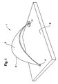
- the half-loop antenna known from the literature consists of a semicircular over a ground plane guided metallic conductor or antenna bracket, like this is shown by way of example in FIG. 5.
- the Mode of operation of the known half-loop antenna corresponds to that of a folding monopoly.
- their radiation diagram is in the vertical and the horizontal plane approximately that a monopoly, for example a ⁇ / 4 radiator.
- One on a resonance length of ⁇ / 2 half loop antenna has a height of 83% of a ⁇ / 4 radiator.
- a ⁇ / 2 Halfloop antenna has its maximum voltage on half Antenna length, i.e. in the highest point of the conductor bracket above the ground plane.
- An antenna unit is known from EP-0 684 661 which a substrate and an emitter mounted on the substrate whose radiating part is a flat plate, which is arranged parallel to the substrate.
- the radiant Part has a feed connection and an earth connection.
- GPS satellite-based vehicle navigation
- the GPS antenna preferably as a stripline antenna Cross radiation formed, consists of a plate a dielectric material on one side, as Ground surface, completely metallized and on the other Side, in the direction of radiation, with a partial Metallization is provided, and being the cellular antenna Has all-round characteristics in the horizontal radiation diagram and the large conductive area for this antenna as Ground reference surface is used.
- a half loop antenna according to the generic term of claim 1 is known from US 3,015,101.
- the invention is therefore based on the object Halfloop antenna to develop, especially in the automotive field can be used for mobile communications, whereby while maintaining good antenna characteristics compact and small-area design is achieved.
- a half loop antenna with a metallic antenna bracket, opposite one as a mass laid out basic level and the antenna bracket on on one side is connected to the basic level and on the other side has the antenna signal, the Antenna bracket formed by a surface, the outer edge of which forms a convex curve, i.e. is curved outwards, and wherein the area of the antenna bracket Ground plane sloping and parallel is arranged.
- the handling of the Antenna bracket the shape of a pointed at its ends tapering ellipse.
- the Antenna signal side of the antenna bracket an inductance inserted. Furthermore, the connection between the Antenna bracket and the base level by another Inductance take place.
- the flat antenna bracket preferably has on it On the outside a dielectric. Furthermore, the antenna be protected by a radome, the radome being Dielectric can be used.
- the inductance or inductances are preferred designed as a spring, the restoring force of the metallic Surface of the antenna bracket or parts thereof against the radome suppressed.
- the metallic antenna bracket can also be used as a metallic one Surface to be applied on the inside of the radome.
- the antenna area of the half-loop antenna can be used as Skelletantenne be realized, the area of the Antenna bracket through a thin metallic conductor is formed, the outer edge of the antenna area forms.
- the design of the Antenna bracket as a surface with a convex edge an increase the capacity of the antenna with the smallest footprint, whereby a broadband in the frequency band Radiation behavior is achieved. Furthermore, by the Increasing the antenna's own capacitance reduces the impedance at the Resonance or operating frequency to lower values, such as for example 50 ⁇ . advantageously, become neither the horizontal nor the vertical Radiation diagram influenced by the selected geometry or only influenced to a small extent. By increasing the There is the possibility of shortening the capacity mechanical length of the conductor bracket, so that at a corresponding shortening of the mechanical length of the Ladder bracket the height to 50% of a ⁇ / 4 radiator reduced.
- the feed network at least one has first resonance circuit which has an inductance and includes a capacity.
- the half-loop antenna signals in at least two frequency ranges radiate and / or receive.
- one Multi-band capable half-loop antenna realized at the same time is as compact and small-area as possible.
- the dining network comprises at least a first additional impedance, so is chosen that the impedance of the half-loop antenna to a predetermined impedance at the feed point is adapted. To this way you can fine tune the impedance of the Half loop antenna in the frequency bands used realize.
- Another advantage is that the dining network several resonance circuits different Has resonance frequency. This way you can do more realize as two frequency ranges in which the Halfloop antenna can send and / or receive signals at while maintaining their compact and small-area design.
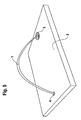
- Fig. 1 shows the first embodiment of the invention
- Half-loop antenna consisting of a flat metallic Antenna bracket 1, which is arranged above a base level 2 is, the antenna bracket 1 at point 3 its feed, i.e. the antenna signal, while the other side contacted the basic level 2 in point 4.
- the half-loop antenna thus acts as a folding monopoly.
- the surface 5 of the antenna bracket 1 the unwinding the shape of a pointed at its ends tapering ellipse. In general, this is the antenna area 5 bounding edge 6 a concave, i.e. domed, closed curve.
- This flat design causes an increase in the capacity of the antenna, so that a Broadband radiation behavior achieved in the frequency band becomes.
- the horizontal and vertical Radiation diagram of the flat in the present case curved geometry not or only to a small extent being affected.
- the one equipped with the flat geometry Antenna compared to the half-loop antennas known from the literature one to the sending source or to the receiver matched impedance, a higher bandwidth and a lower height with an unchanged radiation diagram on.
- the widening of the antenna geometry corresponds in its Effect of the head capacity with a ⁇ / 4 radiator.
- FIG. 2 shows a further embodiment of the half loop antenna.
- an inductance 7 i.e. Extension coil
- the Extension coil 7 inserted at entry point 3.
- the surface 5 of the antenna bracket 1 runs essentially obliquely (viewed at earth point 4) to parallel (in the Figure viewed at the rear edge of the surface 6) Ground plane 1. Since the ⁇ / 2 half-loop antenna has its current maxima at the conductor bracket ends, i.e. at entry point 3 and at Has contact point 4 to the ground plate 2, so it unfolds there their greatest impact.
- Figure 3 shows a third embodiment of the Halloop antenna according to the invention, in which a further Extension coil 8 (inductance) in the antenna bracket 1 is inserted.
- the further extension coil 8 is on the the contacting with the base level 2 4 of the Antenna bracket 1 inserted and distributed the Total inductance on the two extension coils on the Ladder bracket ends, which gives you a spotlight that so is formed that it has a metallic surface 5 larger Expansion above the base level 2 (ground plate) with a has a certain distance from it.
- an antenna according to the above embodiments can optimize the effect of a radome as a dielectric be exploited.
- the goal is to keep the distance as low as possible between antenna and radome.
- the metallic surface of the antenna bracket directly on the radome see above can act through the effect of the radome as a dielectric Ironing area and thus overall length and width reduced further become.
- There is also an undefined detuning of the antenna prevented by a different distance of the Radome to the metallic surface of the conductor bracket due to Manufacturing tolerances can arise.
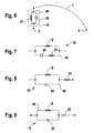
- Fig. 4 shows a further embodiment of the Halloop antenna according to the invention, in which the Head capacity is designed in the form of a skeletal antenna.
- the metallic surface 5 of the Antenna bracket 1 is through a thin metallic conductor 9 replaced, which represents the outer edge 6 of the surface 5.
- a skeletal antenna according to the fig shown second embodiment advantageously, with such an antenna there is the possibility of the half-loop antenna additional antennas, for example a GPS patch antenna.
- So-called two-band antennas are used in two-band operation used at two operating frequencies can send and / or receive electromagnetic waves. Such a two-band antenna shows in these two Operating frequencies each have a resonance.
- the feed network 10 between the Antenna bracket 1 and one of the antenna connections 3, 4 Feed network 10 is inserted, the feed network 10 at least one first resonance circuit 40; 50 has the one inductor 15; 16 and a capacity 20; 21 includes.
- the antenna connections 3, 4 are on the one hand Entry point 3 and on the other hand the contact point 4 to Ground level 2, which forms a reference potential.
- the feed network 10 is between the Antenna bracket 1 and the feed point 3 arranged. It could just as well be between the antenna bracket 1 and the contact point 4 to the basic level 2 be inserted.
- the feed network 10 as the first resonance circuit a first parallel resonance circuit 40.
- the first Parallel resonance circuit 40 provides a parallel connection a first inductance 15 and a first capacitance 20 represents
- the first inductance 15 brings about a first resonance frequency f r1 below the resonance frequency, which would be achieved if the antenna bracket 1 were used alone for the half-loop antenna, ie without the feed network 10.
- the first capacitance 20 brings about a second resonance frequency f r2 , which is greater than the first resonance frequency f r1 and is above the resonance frequency which would be achieved if the antenna bracket 1 were used alone for the half-loop antenna, ie without the feed network 10.
- the result is a two-band antenna which comprises a first frequency range with the first resonance frequency f r1 as the center frequency and a second frequency range with the second resonance frequency f r2 as the center frequency for transmitting and / or receiving signals
- the resonance frequency of the half-loop antenna at sole use of the antenna bracket 1, ie without the feed network 10 would lie between the two frequency ranges.
- the first inductance 15 and the first capacitance 20 must be dimensioned such that the resonance frequency of the first parallel resonance circuit 40 lies between the two realized frequency bands or between the two resonance frequencies f r1 , f r2 .
- the size of the antenna bracket 1 is reduced.
- the impedance of the feed network 10 makes sense to dimension the impedance of the feed network 10 such that, together with the impedance of the antenna bracket 1, it results in a predetermined impedance at the feed-in point 3 in both frequency ranges used for transmitting and / or receiving signals.
- an impedance specified for this contact point 4 must then be set accordingly by suitable dimensioning of the impedance of the feed network 10.
- the desired impedance at the feed point 3 or at the contact point 4 to the base plane 2 can be achieved by dimensioning the first inductance 15 and the first capacitance 20 accordingly, provided that the requirement is met that the resonance frequency of the first parallel resonance circuit 40 between the first resonance frequency f r1 and the second resonance frequency f r2 .
- the first inductance 15 and the first capacitance 20 cannot be dimensioned in such a way that the desired impedance is reached at the feed-in point 3 or at the contact point 4 with the base plane 2, it can also be provided according to the invention to arrange at least one first additional impedance in the feed network 10 , which is chosen so that the half-loop antenna is matched to the predetermined impedance at the antenna connection 3, 4 connected to the feed network 10.
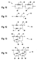
- the at least one first additional impedance can be arranged in a circuit branch of the first parallel resonance circuit 40 or in series or parallel to the first parallel resonance circuit 40. According to FIG. 7, starting from the exemplary embodiment according to FIG.
- the first parallel resonance circuit 40 is expanded, for example, in such a way that a matching inductor 25 is connected in series to the first capacitance 20, which is dimensioned such that the predetermined impedance is set at the feed-in point 3.
- a matching inductor 25 can also be connected in series with the first parallel resonance circuit 40 in order to achieve the desired adaptation to the impedance at the feed point 3 according to FIG. 6.
- an appropriately dimensioned matching capacitor 26 can also be used for impedance matching, which in the example according to FIG. 9 is connected in series with the parallel resonance circuit 40, but could also be connected in series with the first inductance 15 in the parallel resonance circuit 40.
- the dining network 10, which in the example according to FIG first parallel resonance circuit 40 with the first inductance 15 and the first capacitance 20 comprises a simple and inexpensive solution for the realization of a half loop antenna represents that in two different frequency ranges Can send and / or receive signals.
- the feed network 10 can also be used as Series resonance circuit be formed, as in Figure 11 based of a first series resonant circuit 50 is shown.
- the first series resonant circuit 50 comprises a second one Inductor 16, which is in series with a second capacitance 21 is switched.
- a vote or fine-tuning of the Impedance of the first series resonant circuit 50 to achieve the predetermined impedance of the half-loop antenna on Entry point 3 or at contact point 4 to base level 2 can now start from the first series resonant circuit 50 be achieved, one or more accordingly dimensioned additional impedances in the feed network 10 insert.
- This can be done, for example, by Parallel connection of another capacity to the second Inductance 16 or to the entire first series resonance circuit 50 happen. Accordingly, this can also be done by the second capacitance 21 or the entire first Series resonant circuit 50 a further inductance in parallel turn.
- the feed network 10 for example a parallel connection of two Series resonant circuits 50, 55 comprise, as in FIG. 12 shown.
- the first Series resonance circuit 50, a second series resonance circuit 55 connected in parallel, the second series resonant circuit 55 from a fourth inductor 31 and one in series switched fourth capacitance 36 is formed.
- the dining network 10 two connected in series Parallel resonance circuits 40, 45 includes.
- Parallel resonance circuit 45 connected in series, one Parallel connection from a third inductor 30 and a third capacitance 35 forms.
- Figure 13 is as another example a parallel connection of the first Parallel resonance circuit 40 with the first Series resonance circuit 50 shown, these Parallel connection forms the feed network 10.
- a Three-band half-loop antenna by connecting a series Parallel resonance circuit with a series resonance circuit achieve.
- three frequency ranges can be realize in which the half-loop antenna send signals and / or can receive.
- the inductors and Capacities of the two respective resonance circuits dimension that the resonance frequencies of each Resonance circuits between those for transmission and / or Receive usable frequency ranges of the half-loop antenna lie.
- Even more frequency bands for sending and / or receiving with the half loop antenna can be used by using further Achieve resonance circuits. So could more than two Parallel resonance circuits in series or more than two Series resonance circuits are connected in parallel. Can too several series and parallel resonance circuits to each other in Can be connected in series or in parallel, towards it make sure that there are not two series resonance circuits to each other be connected in series and that not two Parallel resonance circuits connected in parallel to each other become.
- the resonance circuits are each so closed dimension that their resonance frequencies between the individual for sending and / or receiving signals used frequency ranges of the half loop antenna are and differ from each other.
- Figure 14 shows an example a parallel connection of the first series resonant circuit 50 with a series connection of the first parallel resonance circuit 40 and the second parallel resonance circuit 45 the first series resonant circuit 50, for example, also one Series connection from more than two parallel resonance circuits or a series connection of several Parallel resonance circuits and a series resonance circuit be connected in parallel.
- Fine-tuning the impedance matching in such Half loop antennas with more than two frequency ranges for Sending and / or receiving signals takes place in the described way by appropriate insertion additional impedances, as shown in Figure 7, Figure 8 and Figure 9 has been described.
- additional impedances can be used. These can be like described in one or more circuit branches of a each resonance circuit of the feed network 10 or in series or be arranged in parallel.
- the antennas according to the preferred embodiments have both in the side view and in the top view tapered profile, which is aerodynamically favorable Has properties.
- Has properties When using two Extension coils whose inductance is asymmetrical distributed, you can see the slope angle of the side profile determine or change the shape of the profile itself. In order to is both a straight ascending and one with a Curvature increasing profile can be realized.
- the antenna is suitable for good aerodynamic properties also as an on-glass antenna, since it is installed at the Upper edge of the front or rear window due to its wedge-shaped Forming forms a smooth transition to the body.
- the area of application of the flat antennas described above is among other things, when sending and receiving signals in the GSM band.
- a rod antenna for radio reception in which another antenna for sending and receiving signals could be integrated in the GSM band, does not exist or stands not available, for example because it is in the form of a Rear window antenna was realized, there is Possibility to separate such a GSM antenna to install.
- Such flat antennas are preferred installed where antennas in the vehicle geometry should be integrated.
- radiation can the occupant with an omnidirectional antenna be minimized if these are in an installation position located on or directly on the vehicle roof.
- the antenna By dimensioning the antenna accordingly these also for vertically polarized transmission or reception electromagnetic waves in other frequency bands, for example in the e-network.
Landscapes
- Details Of Aerials (AREA)
- Variable-Direction Aerials And Aerial Arrays (AREA)
Description
Die Erfindung betrifft eine Halfloop-Antenne, insbesondere eine Halfloop-Antenne zur Verwendung an einem Kraftfahrzeug. Die aus der Literatur bekannte Halfloop-Antenne besteht aus einem halbkreisförmig über eine Grundplatte (groundplane) geführten metallischen Leiter- oder Antennenbügel, wie dies beispielhaft in der Fig. 5 dargestellt ist. Die Wirkungsweise der bekannten Halfloop-Antenne entspricht der eines Faltmonopols. Ferner ist ihr Strahlungsdiagramm in der vertikalen und der horizontalen Ebene näherungsweise das eines Monopols, beispielsweise eines λ/4-Strahlers. Eine auf eine Resonanzlänge von λ/2 ausgelegte Halfloop-Antenne besitzt eine Bauhöhe von 83% eines λ/4-Strahlsers. Speist man die eine Seite des Leiterbügels und kontaktiert die andere Seite mit der Grundplatte oder Masseebene, so weist die Antennen bei ihrer Resonanzfrequenz eine Impedanz oberhalb von 100 Ω auf. Ferner bewirkt die Erhöhung der Kapazität einer Antenne ein im Frequenzband breitbandigeres Abstrahlverhalten. Ferner kann die Erhöhung der Kapazität einer Antenne wirksam durch die Vergrößerung ihrer Dimension in ihrem Spannungsmaximum erreicht werden. Eine λ/2 Halfloop-Antenne hat ihr Spannungsmaximum auf der halben Antennenlänge, also in dem höchsten Punkt des Leiterbügels über der Masseebene. The invention relates to a half-loop antenna, in particular a half loop antenna for use on a motor vehicle. The half-loop antenna known from the literature consists of a semicircular over a ground plane guided metallic conductor or antenna bracket, like this is shown by way of example in FIG. 5. The Mode of operation of the known half-loop antenna corresponds to that of a folding monopoly. Furthermore, their radiation diagram is in the vertical and the horizontal plane approximately that a monopoly, for example a λ / 4 radiator. One on a resonance length of λ / 2 half loop antenna has a height of 83% of a λ / 4 radiator. feeds one side of the conductor bracket and contacts the other side with the base plate or ground plane, so points the antennas have an impedance at their resonance frequency above 100 Ω. Furthermore, increasing the The capacity of an antenna is broader in the frequency band Radiation. Furthermore, the increase in capacity an antenna effective by increasing its size can be reached in their maximum voltage. A λ / 2 Halfloop antenna has its maximum voltage on half Antenna length, i.e. in the highest point of the conductor bracket above the ground plane.
Aus der EP-0 684 661 ist eine Antenneneinheit bekannt, die ein Substrat und einen auf dem Substrat befestigten Strahler aufweist, dessen strahlender Teil eine flache Platte ist, die parallel zum Substrat angeordnet ist. Der strahlende Teil weist einen Zuführanschluß und einen Erdanschluß auf.An antenna unit is known from EP-0 684 661 which a substrate and an emitter mounted on the substrate whose radiating part is a flat plate, which is arranged parallel to the substrate. The radiant Part has a feed connection and an earth connection.
Ferner ist aus der DE 195 14 556 eine Flachantennen-Anordnung für Frequenzen im GHz-Bereich bekannt, die aus einer Antenne für satellitengestützte Fahrzeugnavigation (GPS) und mindestens einer Antenne für Mobilfunk besteht, die in einem gemeinsamen Gehäuse auf einer leitenden Fläche größerer Ausdehnung, insbesondere auf einer Fahrzeugkarosserie, angeordnet sind. Dabei ist die GPS-Antenne vorzugsweise als Streifenleiterantenne mit Querstrahlung ausgebildet, besteht aus einer Platte aus einem dielektrischen Material, die auf einer Seite, als Massefläche, durchgängig metallisiert und auf der anderen Seite, in Strahlungsrichtung, mit einer partiellen Metallisierung versehen ist, und wobei die Mobilfunk-Antenne Rundumcharakteristik im horizontalen Strahlungsdiagramm hat und die große leitende Fläche für diese Antenne als Massebezugsfläche verwendet wird.Furthermore, from DE 195 14 556 is a flat antenna arrangement known for frequencies in the GHz range that come from an antenna for satellite-based vehicle navigation (GPS) and at least one antenna for mobile communications, those in a common housing on a conductive surface larger extension, especially on one Vehicle body, are arranged. Here is the GPS antenna preferably as a stripline antenna Cross radiation formed, consists of a plate a dielectric material on one side, as Ground surface, completely metallized and on the other Side, in the direction of radiation, with a partial Metallization is provided, and being the cellular antenna Has all-round characteristics in the horizontal radiation diagram and the large conductive area for this antenna as Ground reference surface is used.
Eine Halfloop-Antenne gemäß dem Oberbegriff des Anspruchs 1 ist aus der US 3 015 101 bekannt.A half loop antenna according to the generic term of claim 1 is known from US 3,015,101.
Nachteilig bei den bekannten Flachantennen ist ihr notwendiger Flächenbedarf, insbesondere bei der Verwendung an Kraftfahrzeugen.It is disadvantageous in the known flat antennas Required space, especially when using on motor vehicles.
Der Erfindung liegt daher die Aufgabe zugrunde, eine Halfloop-Antenne zu entwickeln, die insbesondere im Kfz-Bereich für den Mobilfunk eingesetzt werden kann, wobei unter Beibehaltung einer guten Antennencharakteristik eine möglichst kompakte und kleinflächige Bauform erzielt wird. The invention is therefore based on the object Halfloop antenna to develop, especially in the automotive field can be used for mobile communications, whereby while maintaining good antenna characteristics compact and small-area design is achieved.
Die Aufgabe wird durch die Merkmale des Anspruchs 1 gelöst. Bevorzugte Ausgestaltungen der Erfindung sind Gegenstand der Unteransprüche.The object is solved by the features of claim 1. Preferred embodiments of the invention are the subject of Dependent claims.
Bei einer erfindungsgemäßen Halfloop-Antenne mit einem metallischen Antennenbügel, der gegenüber einer als Masse ausgelegten Grundebene angeordnet und der Antennenbügel auf der einen Seite mit der Grundebene verbunden ist und auf der anderen Seite das Antennensignal aufweist, wird der Antennenbügel durch eine Fläche gebildet, deren äußerer Rand eine konvexe Kurve bildet, d.h. nach außen gewölbt ist, und wobei die Fläche des Antennenbügels zur Grundebene schräg und parallel angeordnet ist.In a half loop antenna according to the invention with a metallic antenna bracket, opposite one as a mass laid out basic level and the antenna bracket on on one side is connected to the basic level and on the other side has the antenna signal, the Antenna bracket formed by a surface, the outer edge of which forms a convex curve, i.e. is curved outwards, and wherein the area of the antenna bracket Ground plane sloping and parallel is arranged.
In einer bevorzugten Ausführungsform hat die Abwicklung des Antennenbügels die Form einer an ihren Enden spitz zulaufenden Ellipse.In a preferred embodiment, the handling of the Antenna bracket the shape of a pointed at its ends tapering ellipse.
Um die Bauhöhe der Antenne weiter zu verringern, ist an der Antennensignalseite des Antennenbügels eine Induktivität eingefügt. Ferner kann die Verbindung zwischen dem Antennenbügel und der Grundebene durch eine weitere Induktivität erfolgen.To further reduce the height of the antenna, the Antenna signal side of the antenna bracket an inductance inserted. Furthermore, the connection between the Antenna bracket and the base level by another Inductance take place.
Vorzugsweise weist der flächige Antennenbügel an seiner Außenseite ein Dielektrikum auf. Ferner kann die Antenne durch einen Radom geschützt sein, wobei das Radom als Dielektrikum eingesetzt werden kann.The flat antenna bracket preferably has on it On the outside a dielectric. Furthermore, the antenna be protected by a radome, the radome being Dielectric can be used.
Vorzugsweise sind die Induktivität bzw. die Induktivitäten als Feder ausgebildet, deren Rückstellkraft die metallische Fläche des Antennenbügels oder Teile davon gegen das Radom drückt.The inductance or inductances are preferred designed as a spring, the restoring force of the metallic Surface of the antenna bracket or parts thereof against the radome suppressed.
Der metallische Antennenbügel kann auch als metallische Fläche auf der Innenseite des Radoms aufgebracht sein.The metallic antenna bracket can also be used as a metallic one Surface to be applied on the inside of the radome.
Ferner kann die Antennenfläche der Halfloop-Antenne als Skelletantenne realisiert sein, wobei die Fläche des Antennenbügels durch einen dünnen metallischen Leiter gebildet wird, der den äußeren Rand der Antennenfläche bildet.Furthermore, the antenna area of the half-loop antenna can be used as Skelletantenne be realized, the area of the Antenna bracket through a thin metallic conductor is formed, the outer edge of the antenna area forms.
Vorteilhafterweise wird durch die Ausgestaltung des Antennenbügels als Fläche mit konvexem Rand eine Erhöhung der Kapazität der Antenne bei kleinster Grundfläche bewirkt, wodurch ein im Frequenzband breitbandigeres Abstrahlverhalten erzielt wird. Ferner kann durch die Erhöhung der Eigenkapazität der Antenne die Impedanz bei der Resonanz bzw. Betriebsfrequenz zu niedrigeren Werten, wie beispielsweise 50 Ω, verschoben werden. Vorteilhafterweise werden weder das horizontale noch das vertikale Strahlungsdiagramm durch die gewählte Geometrie beeinflußt bzw. nur in geringem Maße beeinflußt. Durch die Erhöhung der Kapazität bietet sich die Möglichkeit einer Verkürzung der mechanischen Länge des Leiterbügels, so daß bei einer entsprechenden Verkürzung der mechanischen Länge des Leiterbügels sich die Bauhöhe auf 50% eines λ/4-Strahlers verringert.Advantageously, the design of the Antenna bracket as a surface with a convex edge an increase the capacity of the antenna with the smallest footprint, whereby a broadband in the frequency band Radiation behavior is achieved. Furthermore, by the Increasing the antenna's own capacitance reduces the impedance at the Resonance or operating frequency to lower values, such as for example 50 Ω. advantageously, become neither the horizontal nor the vertical Radiation diagram influenced by the selected geometry or only influenced to a small extent. By increasing the There is the possibility of shortening the capacity mechanical length of the conductor bracket, so that at a corresponding shortening of the mechanical length of the Ladder bracket the height to 50% of a λ / 4 radiator reduced.
Besonders vorteilhaft ist es, daß zwischen dem Antennenbügel und einem der Antennenanschlüsse ein Speisenetzwerk eingefügt ist, wobei das Speisenetzwerk mindestens eine erste Resonanzschaltung aufweist, die eine Induktivität und eine Kapazität umfaßt. Auf diese Weise kann die Halfloop-Antenne in mindestens zwei Frequenzbereichen Signale abstrahlen und/oder empfangen. Somit wird eine mehrbandfähige Halfloop-Antenne realisiert, die gleichzeitig eine möglichst kompakte und kleinflächige Bauform aufweist.It is particularly advantageous that between the antenna bracket and one of the antenna connections a feed network is inserted, the feed network at least one has first resonance circuit which has an inductance and includes a capacity. In this way, the half-loop antenna signals in at least two frequency ranges radiate and / or receive. Thus, one Multi-band capable half-loop antenna realized at the same time is as compact and small-area as possible.
Ein weiterer Vorteil besteht darin, daß das Speisenetzwerk mindestens eine erste zusätzliche Impedanz umfaßt, die so gewählt ist, daß die Impedanz der Halfloop-Antenne auf eine vorgegebene Impedanz am Speisepunkt angepaßt ist. Auf diese Weise läßt sich eine Feinabstimmung der Impedanz der Halfloop-Antenne in den jeweils verwendeten Frequenzbändern realisieren.Another advantage is that the dining network comprises at least a first additional impedance, so is chosen that the impedance of the half-loop antenna to a predetermined impedance at the feed point is adapted. To this This way you can fine tune the impedance of the Half loop antenna in the frequency bands used realize.
Ein weiterer Vorteil besteht darin, daß das Speisenetzwerk mehrere Resonanzschaltkreise unterschiedlicher Resonanzfrequenz aufweist. Auf diese Weise lassen sich mehr als zwei Frequenzbereiche realisieren, in denen die Halfloop-Antenne Signale senden und/oder empfangen kann, bei gleichzeitiger Beibehaltung ihrer kompakten und kleinflächigen Bauform.Another advantage is that the dining network several resonance circuits different Has resonance frequency. This way you can do more realize as two frequency ranges in which the Halfloop antenna can send and / or receive signals at while maintaining their compact and small-area design.
Bevorzugte Ausführungsformen der Erfindung werden
nachfolgend anhand der Zeichnungen erläutert.
Fig. 1 zeigt die erste Ausführungsform der erfindungsgemäßen
Halfloop-Antenne, bestehend aus einem flächigen metallischen
Antennenbügel 1, der oberhalb einer Grundebene 2 angeordnet
ist, wobei der Antennenbügel 1 am Punkt 3 seine Einspeisung,
d.h. das Antennensignal, aufweist, während die andere Seite
im Punkt 4 die Grundebene 2 kontaktiert. Die Halfloop-Antenne
wirkt somit als Faltmonopol. In der bevorzugten
Ausführungsform hat die Fläche 5 des Antennenbügels 1 bei
der Abwicklung die Form einer an ihren Enden spitz
zulaufenden Ellipse. Allgemein ist der die Antennenfläche 5
begrenzende Rand 6 eine konkave, d.h. nach außen gewölbte,
geschlossene Kurve. Durch diese flächige Ausgestaltung wird
eine Erhöhung der Kapazität der Antenne bewirkt, so daß ein
im Frequenzband breitbandigeres Abstrahlverhalten erzielt
wird. Ferner kann durch die Erhöhung der Eigenkapazität die
Impedanz der Antenne bei der Resonanz- bzw. Betriebsfrequenz
zu niedrigeren Werten, beispielsweise 50 Ω, verschoben
werden, wobei jedoch das horizontale wie vertikale
Strahlungsdiagramm von der flächigen, im vorliegenden Fall
gekrümmten Geometrie nicht oder nur in geringem Maß
beeinflußt wird.Fig. 1 shows the first embodiment of the invention
Half-loop antenna consisting of a flat metallic
Antenna bracket 1, which is arranged above a
Ferner bietet die Erhöhung der Kapazität die Möglichkeit einer Verkürzung der mechanischen Länge des Leiterbügels. Beispielsweise reduziert sich bei einer entsprechenden Verkürzung der mechanischen Länge des Leiterbügels die Bauhöhe auf ca. 50% eines λ/4-Strahlers.Furthermore, increasing the capacity offers the possibility a reduction in the mechanical length of the conductor bracket. For example, with a corresponding one Shortening the mechanical length of the conductor bracket Height to approx. 50% of a λ / 4 radiator.
Ferner weist die mit der flächigen Geometrie ausgestattete Antenne gegenüber den aus der Literatur bekannten Halfloop-Antennen eine an die Sendequelle bzw. an den Empfänger angepaßte Impedanz, eine höhere Bandbreite sowie eine geringere Bauhöhe bei einem unveränderten Strahlungsdiagramm auf. Die Antennengeometrieverbreiterung entspricht in ihrer Wirkung der Kopfkapazität bei einem λ/4-Strahler.Furthermore, the one equipped with the flat geometry Antenna compared to the half-loop antennas known from the literature one to the sending source or to the receiver matched impedance, a higher bandwidth and a lower height with an unchanged radiation diagram on. The widening of the antenna geometry corresponds in its Effect of the head capacity with a λ / 4 radiator.
Figur 2 zeigt eine weitere Ausführungsform der Halfloop-Antenne.
Um die mechanische Länge des Antennenbügels 1 zu
verkürzen, kann eine Induktivität 7, d.h.
Verlängerungsspule, in den Antennenbügel 1 eingefügt werden.
In der dargestellten zweiten Ausführungsform wird die
Verlängerungsspule 7 am Einspeisepunkt 3 eingefügt. Dabei
ergibt sich als Form des Antennenbügels 1 in der Abwicklung
eine Ellipse, die nur an einem Ende spitz zuläuft. Ferner
verläuft die Fläche 5 des Antennenbügels 1 im wesentlichen
schräg (am Massepunkt 4 betrachtet) bis parallel (in der
Figur am hinteren Rand der Fläche 6 betrachtet) zur
Grundebene 1. Da die λ/2-Halfloop-Antenne ihre Strommaxima
an den Leiterbügelenden, d.h. am Einspeisepunkt 3 und am
Kontaktpunkt 4 zur Masseplatte 2 hat, so entfaltet sie dort
ihre größte Wirkung. Durch die Einfügung der
Verlängerungsspule 7 an der Einspeisestelle 3 des
Antennenbügels 1 bleibt als Strahler nur das durch die
Verkürzung verbleibende Restsegment, d.h. die Fläche 5, des
Leiterbügels 1 erhalten. Damit ist eine weitere Verringerung
der Bauhöhe auf 30% eines λ/4-Strahlers sowie eine
Verkürzung der Baulänge möglich. Das entspricht einer
Bauhöhe von 0,08 λ. Da durch die Kopfkapazität die
Bandbreite des Strahlers vorher erheblich vergrößert wurde,
kann die durch die Verlängerungsspule eingetretene
Bandbreitenverringerung in Kauf genommen werden. Zusätzlich
weist die von dieser Antenne gemäß der zweiten
Ausführungsform abgestrahlte Leistung im Nutzfrequenzband
gegenüber der eines λ/4-Strahlers keine deutlichen Einbußen
auf.FIG. 2 shows a further embodiment of the half loop antenna.
To the mechanical length of the antenna bracket 1 too
shorten, an
Figur 3 zeigt eine dritte Ausführungsform der
erfindungsgemäßen Halfloop-Antenne, bei der eine weitere
Verlängerungsspule 8 (Induktivität) in den Antennenbügel 1
eingefügt ist. Die weitere Verlängerungsspule 8 ist an der
die mit der Grundebene 2 kontaktierenden Stelle 4 des
Antennenbügels 1 eingefügt und verteilt die
Gesamtinduktivität auf die beiden Verlängerungsspulen an den
Leiterbügelenden, wodurch man einen Strahler erhält, der so
ausgebildet ist, daß er eine metallische Fläche 5 größerer
Ausdehnung über der Grundebene 2 (Masseplatte) mit einem
gewissen Abstand von dieser besitzt.Figure 3 shows a third embodiment of the
Halloop antenna according to the invention, in which a further
Extension coil 8 (inductance) in the antenna bracket 1
is inserted. The further extension coil 8 is on the
the contacting with the
Bei Verwendung einer Antenne im mobilen Einsatz ist es sinnvoll, diese mit einem Radom zum Schutz gegen Wettereinflüsse zu schützen.When using an antenna in mobile use it is sensible to protect this with a radome To protect weather influences.
Ferner kann am wirksamsten die Erhöhung der Antennenkapazität durch die Vergrößerung ihrer Dimension in ihrem Spannungsmaximum bzw. durch die Belegung mit einem Dielektrikum an dieser Stelle erreicht werden. Daher können die Antennen gemäß den drei Ausführungsformen an ihrer Oberseite mit einem Dielektrikum belegt werden, um die Antennenkapazität zu erhöhen.Furthermore, increasing the Antenna capacity by increasing its dimension in their maximum voltage or by assigning one Dielectric can be achieved at this point. Therefore can the antennas according to the three embodiments on their To be covered with a dielectric Increase antenna capacity.
Bei einer Antenne entsprechend den obigen Ausführungsformen kann somit die Wirkung eines Radoms als Dielektrikum optimal ausgenutzt werden. Um ferner die Bauhöhe der Antenne möglichst niedrig zu halten, ist man bestrebt, den Abstand zwischen Antenne und Radom zu minimieren. Liegt nun die metallische Fläche des Antennenbügels direkt am Radom an, so kann durch die Wirkung des Radoms als Dielektrikum die Bügelfläche und somit Baulänge und -breite weiter verringert werden. Zudem wird eine undefinierte Verstimmung der Antenne verhindert, die durch einen unterschiedlichen Abstand des Radoms zur metallischen Fläche des Leiterbügels aufgrund von Fertigungstoleranzen entstehen kann.With an antenna according to the above embodiments can optimize the effect of a radome as a dielectric be exploited. To further the height of the antenna The goal is to keep the distance as low as possible between antenna and radome. Now is the metallic surface of the antenna bracket directly on the radome, see above can act through the effect of the radome as a dielectric Ironing area and thus overall length and width reduced further become. There is also an undefined detuning of the antenna prevented by a different distance of the Radome to the metallic surface of the conductor bracket due to Manufacturing tolerances can arise.
Für alle obigen drei Ausführungsformen ist daher eine Ausführung fertigungstechnisch günstig, bei der die metallische Fläche des Antennenbügels oder Teile davon direkt auf der Innenseite des Radoms befestigt oder im bevorzugtem Falle aufgedampft werden, und dann mit dem Rest des Antennenbügels 1 kontaktiert werden. For all three above embodiments, there is therefore one Execution technically favorable, in which the metallic surface of the antenna bracket or parts thereof directly attached to the inside of the radome or in the preferred case are evaporated, and then with the rest of the antenna bracket 1 can be contacted.
Ferner ist es möglich, die Verlängerungsspulen 7, 8
entsprechend der zweiten oder dritten Ausführungsform so
auszubilden, daß sie als Feder funktionieren, deren
Rückstellkraft die metallische Fläche des Antennenbügels 1
oder Teile davon gegen das Radom drückt.It is also possible to extend the
Fig. 4 zeigt eine weitere Ausführungsform der
erfindungsgemäßen Halfloop-Antenne, bei der die
Kopfkapazität in Form einer Skelettantenne ausgebildet ist.
Mit anderen Worten, die metallische Fläche 5 des
Antennenbügels 1 wird durch einen dünnen metallischen Leiter
9 ersetzt, der den äußeren Rand 6 der Fläche 5 darstellt.
Hier ist bildlich eine Skelettantenne entsprechend der
zweiten Ausführungsform dargestellt. Vorteilhafterweise
besteht bei einer derartigen Antenne die Möglichkeit, unter
der Halfloop-Antenne zusätzliche Antennen, beispielsweise
eine GPS-Patchantenne, anzuordnen.Fig. 4 shows a further embodiment of the
Halloop antenna according to the invention, in which the
Head capacity is designed in the form of a skeletal antenna.
In other words, the
Um den wachsenden Anforderungen der drahtlosen Kommunikation gerecht zu werden, finden in zunehmendem Maße Mehrbandantennen Verwendung.To meet the growing demands of wireless communication do justice to it increasingly Multi-band antennas use.
Im Zweibandbetrieb werden sogenannte Zweiband-Antennen eingesetzt, die bei zwei Betriebsfrequenzen elektromagnetische Wellen senden und/oder empfangen können. Eine solche Zweiband-Antenne weist bei diesen beiden Betriebsfrequenzen jeweils eine Resonanz auf.So-called two-band antennas are used in two-band operation used at two operating frequencies can send and / or receive electromagnetic waves. Such a two-band antenna shows in these two Operating frequencies each have a resonance.
Im Trend für solche Mehrbandanwendungen liegen vor allen Dingen Flachantennen, die leicht zu integrieren sind oder sich für einen versteckten Einbau, beispielsweise in einem Kraftfahrzeug eignen. Um bei solchen Flachantennen eine Abstrahlung und/oder einen Empfang von Signalen bei mehreren Betriebsfrequenzen zu erreichen, sind entweder mehrere Resonatorelemente erforderlich, die sich in ihrer Resonanzfrequenz unterscheiden und entweder mit einem gemeinsamen Einspeisepunkt verbunden oder als Parasitärresonatoren an einen Hauptresonator angekoppelt sind, oder es werden Strahlerelemente eingesetzt, die bei mehreren Frequenzen schwingfähig sind.The trend for such multi-band applications is above all Things flat antennas that are easy to integrate or for a hidden installation, for example in a Suitable for motor vehicles. To such a flat antenna Radiation and / or reception of signals in several Operating frequencies are either several Resonator elements required in their Distinguish resonance frequency and either with a common entry point connected or as Parasitic resonators coupled to a main resonator are, or radiator elements are used, which at several frequencies are capable of oscillation.
Sowohl bei der Verwendung mehrerer Resonatorelemente als auch bei der Verwendung von Strahlerelementen, die bei mehreren Frequenzen schwingfähig sind, wird Raum beansprucht, der häufig nicht in ausreichendem Maß zur Verfügung steht.Both when using multiple resonator elements as also when using radiator elements that are used several frequencies are oscillatable, there will be space claimed, which is often not sufficient to Available.
Daher stellt sich die Aufgabe, eine solche Flachantenne zu realisieren, die bei Verwendung nur eines Resonatorelementes, das nicht bei mehreren Frequenzen schwingfähig ist, dennoch einen Sende- und/oder Empfangsbetrieb bei mehreren Betriebsfrequenzen zu realisieren.Therefore, the task arises of such a flat antenna realize that when using only one Resonator element that is not at multiple frequencies is capable of oscillation, nevertheless a transmission and / or Receive operation at multiple operating frequencies realize.
Diese Aufgabe wird dadurch gelöst, daß zwischen dem
Antennenbügel 1 und einem der Antennenanschlüsse 3, 4 ein
Speisenetzwerk 10 eingefügt wird, wobei das Speisenetzwerk
10 mindestens eine erste Resonanzschaltung 40; 50 aufweist,
die eine Induktivität 15; 16 und eine Kapazität 20; 21
umfaßt. Die Antennenanschlüsse 3, 4 sind dabei zum einen der
Einspeisepunkt 3 und zum anderen der Kontaktpunkt 4 zur
Grundebene 2, die ein Bezugspotential bildet.This object is achieved in that between the
Antenna bracket 1 and one of the
Gemäß Figur 6 ist das Speisenetzwerk 10 zwischen dem
Antennenbügel 1 und dem Einspeisepunkt 3 angeordnet. Es
könnte jedoch genau so gut zwischen dem Antennenbügel 1 und
dem Kontaktpunkt 4 zur Grundebene 2 eingefügt sein. Dabei
weist das Speisenetzwerk 10 als erste Resonanzschaltung
einen ersten Parallelresonanzkreis 40 auf. Der erste
Parallelresonanzkreis 40 stellt dabei eine Parallelschaltung
aus einer ersten Induktivität 15 und einer ersten Kapazität
20 dar.According to Figure 6, the
Wie beschrieben kann man mittels einer in den Antennenbügel
1 eingefügten Induktivität die mechanische Länge des
Antennenbügels 1 bei gleichbleibender Resonanzfrequenz
reduzieren. Umgekehrt ist es mittels einer in den
Antennenbügel 1 eingefügten Kapazität möglich, die
mechanische Länge des Antennenbügels 1 bei gleichbleibender
Resonanzfrequenz zu verlängern. Wie beschrieben, entfalten
in den Antennenbügel 1 eingefügte Impedanzen ihre größte
Wirkung im Strommaximum der Halfloop-Antenne. Dies ist bei
der beschriebenen λ/2-Halfloop-Antenne am Einspeisepunkt 3
und am Kontaktpunkt 4 zur Grundebene 2 der Fall. Somit hat
auch das Speisenetzwerk 10 im Einspeisepunkt 3 bzw. im
Kontaktpunkt 4 seine maximale Wirkung.As described you can use one in the antenna bracket
1 inserted inductance the mechanical length of the
Antenna bracket 1 with a constant resonance frequency
to reduce. Conversely, it is in the
Antenna bracket 1 inserted capacity possible that
mechanical length of the antenna bracket 1 with the same
Extend resonance frequency. Unfold as described
impedances inserted into the antenna bracket 1 are their greatest
Effect in the current maximum of the half loop antenna. This is at
the described λ / 2 half-loop antenna at the feed-in point 3
and the case at
Beim Speisenetzwerk 10 gemäß Figur 6 bewirkt die erste
Induktivität 15 eine erste Resonanzfrequenz fr1 unterhalb
der Resonanzfrequenz, die bei alleiniger Verwendung des
Antennenbügels 1 für die Halfloop-Antenne, d.h. ohne
Speisenetzwerk 10, erzielt würde. Die erste Kapazität 20
bewirkt eine zweite Resonanzfrequen fr2, die größer als die
erste Resonanzfrequenz fr1 ist und oberhalb der
Resonanzfrequenz liegt, die bei alleiniger Verwendung des
Antennenbügels 1 für die Halfloop-Antenne, d.h. ohne
Speisenetzwerk 10 erzielt würde. Somit erhält man eine
Zweiband-Antenne, die einen ersten Frequenzbereich mit der
ersten Resonanzfrequenz fr1 als Mittenfrequenz und einen
zweiten Frequenzbereich mit der zweiten Resonanzfrequenz fr2
als Mittenfrequenz zum Senden und/oder Empfangen von
Signalen umfaßt, wobei die Resonanzfrequenz der Halfloop-Antenne
bei alleiniger Verwendung des Antennenbügels 1, d.h.
ohne Speisenetzwerk 10 zwischen den beiden Frequenzbereichen
liegen würde. Die erste Induktivität 15 und die erste
Kapazität 20 müssen dabei so dimensioniert werden, daß die
Resonanzfrequenz des ersten Parallelresonanzkreises 40
zwischen den beiden realisierten Frequenzbändern bzw.
zwischen den beiden Resonanzfrequenzen fr1, fr2 liegt.In the
Gegenüber einer auf die erste Resonanzfrequenz fr1 ausgelegten Einband-Halfloop-Antenne findet eine Baugrößenverringerung des Antennenbügels 1 statt.Compared to a single-band half-loop antenna designed for the first resonance frequency f r1 , the size of the antenna bracket 1 is reduced.
Weiterhin ist es sinnvoll, die Impedanz des Speisenetzwerks
10 so zu dimensionieren, daß sie zusammen mit der Impedanz
des Antennenbügels 1 in beiden zum Senden und/oder zum
Empfangen von Signalen genutzten Frequenzbereichen eine
vorgegebene Impedanz am Einspeisepunkt 3 ergibt. Bei
Anschluß des Speisenetzwerks 10 an den Kontaktpunkt 4 zur
Grundebene 2 ist dann entsprechend eine für diesen
Kontaktpunkt 4 vorgegebene Impedanz durch geeignete
Dimensionierung der Impedanz des Speisenetzwerks 10
einzustellen. Die gewünschte Impedanz am Einspeisepunkt 3
oder am Kontaktpunkt 4 zur Grundebene 2 kann durch
entsprechende Dimensionierung der ersten Induktivität 15 und
der ersten Kapazität 20 erfolgen, sofern dabei die
Erfordernis eingehalten wird, daß die Resonanzfrequenz des
ersten Parallelresonanzkreises 40 zwischen der ersten
Resonanzfrequenz fr1 und der zweiten Resonanzfrequenz fr2
liegt. Läßt sich die erste Induktivität 15 und die erste
Kapzazität 20 nicht so dimensionieren, daß die gewünschte
Impedanz am Einspeisepunkt 3 bzw. am Kontaktpunkt 4 zur
Grundebene 2 erreicht wird, so kann es erfindungsgemäß auch
vorgesehen sein, mindestens eine erste zusätzliche Impedanz
im Speisenetzwerk 10 anzuordnen, die so gewählt ist, daß die
Halfloop-Antenne auf die vorgegebene Impedanz am mit dem
Speisenetzwerk 10 verbundenen Antenennenanschluß 3, 4
angepaßt ist. Dabei kann die mindestens eine erste
zusätzliche Impedanz in einem Schaltungszweig des ersten
Parallelresonanzkreises 40 oder in Serie oder parallel zum
ersten Parallelresonanzkreis 40 angeordnet sein. Gemäß Figur
7 ist ausgehend von dem Ausführungsbeispiel gemäß Figur 6
der erste Parallelresonanzkreis 40 beispielsweise
dahingehend erweitert, daß der ersten Kapazität 20 eine
Anpassungsinduktivität 25 in Serie geschaltet ist, die so
dimensioniert ist, daß die vorgegebene Impedanz am
Einspeisepunkt 3 eingestellt wird. In einem weiteren
Beispiel gemäß Figur 8 kann eine solche
Anpassungsinduktivität 25 auch in Serie zum ersten
Parallelresonanzkreis 40 geschaltet sein, um die gewünschte
Anpassung an die Impedanz am Einspeisepunkt 3 gemäß Figur 6
zu erreichen. Zur Impedanzanpassung kann gemäß Figur 9 auch
ein entsprechend dimensionierter Anpassungskondensator 26
verwendet werden, der im Beispiel gemäß Figur 9 in Serie zum
Parallelresonanzkreis 40 geschaltet ist, aber auch in Serie
zur ersten Induktivität 15 im Parallelresonanzkreis 40
geschaltet sein könnte.Furthermore, it makes sense to dimension the impedance of the
Es kann auch vorgesehen sein, für die Impedanzanpassung mehr
als eine zusätzliche Impedanz im Speisenetzwerk 10
vorzusehen und in der beschriebenen Weise mit dem
Parallelresonanzkreis 40 zu verschalten. Auf diese Weise
wird eine Feinabstimmung der Impedanz der Halfloop-Antenne
an demjenigen Antennenanschluß 3, 4 erzielt, an dem das
Speisenetzwerk 10 angeschlossen ist. Bei Anschluß am
Einspeisepunkt 3 kann beispielsweise eine vorgegebene
Impedanz von 50 Ω vorgesehen sein.It can also be provided for more impedance matching
as an additional impedance in the
Das Speisenetzwerk 10, das im Beispiel nach Figur 6 den
ersten Parallelresonanzkreis 40 mit der ersten Induktivität
15 und der ersten Kapazität 20 umfaßt, stellt eine einfache
und kostengünstige Lösung zur Realisierung einer Halfloop-Antenne
dar, die in zwei verschiedenen Frequenzbereichen
Signale senden und/oder empfangen kann. The
In entsprechender Weise kann das Speisenetzwerk 10 auch als
Serienresonanzkreis ausgebildet sein, wie in Figur 11 anhand
eines ersten Serienresonanzkreises 50 dargestellt ist. Der
erste Serienresonanzkreis 50 umfaßt dabei eine zweite
Induktivität 16, die in Serie zu einer zweiten Kapazität 21
geschaltet ist. Eine Abstimmung oder Feinabstimmung der
Impedanz des ersten Serienresonanzkreises 50 zur Erzielung
der vorgegebenen Impedanz der Halfloop-Antenne am
Einspeisepunkt 3 bzw. am Kontaktpunkt 4 zur Grundebene 2
kann nun ausgehend vom ersten Serienresonanzkreis 50 dadurch
erreicht werden, eine oder mehrere entsprechend
dimensionierte zusätzliche Impedanzen in das Speisenetzwerk
10 einzufügen. Dies kann beispielsweise durch
Parallelschalten einer weiteren Kapazität zur zweiten
Induktivität 16 oder zum gesamten ersten Serienresonanzkreis
50 geschehen. Entsprechend kann dies auch dadurch geschehen,
der zweiten Kapazität 21 oder dem gesamten ersten
Serienresonanzkreis 50 eine weitere Induktivität parallel zu
schalten.Correspondingly, the
Zur Realisierung von mehr als zwei Frequenzbändern für das
Senden und/oder Empfangen von Signalen mittels der Halfloop-Antenne
kann es vorgesehen sein, daß das Speisenetzwerk 10
mehrere Resonanzschaltungen unterschiedlicher
Resonanzfrequenz aufweist. Dabei kann das Speisenetzwerk 10
beispielsweise eine Parallelschaltung aus zwei
Serienresonanzkreisen 50, 55 umfassen, wie in Figur 12
dargestellt. Gemäß Figur 12 ist dabei dem ersten
Serienresonanzkreis 50 ein zweiter Serienresonanzkreis 55
parallel geschaltet, wobei der zweite Serienresonanzkreis 55
aus einer vierten Induktivität 31 und einer dazu in Serie
geschalteten vierten Kapazität 36 gebildet ist. In einem
weiteren Beispiel kann gemäß Figur 10 vorgesehen sein, daß
das Speisenetzwerk 10 zwei in Serie geschaltete
Parallelresonanzkreise 40, 45 umfaßt. Dabei ist dem ersten
Parallelresonanzkreis 40 gemäß Figur 10 ein zweiter
Parallelresonanzkreis 45 in Serie geschaltet, der eine
Parallelschaltung aus einer dritten Induktivität 30 und
einer dritten Kapazität 35 bildet. Gemäß Figur 13 ist als
weiteres Beispiel eine Parallelschaltung des ersten
Parallelresonanzkreises 40 mit dem ersten
Serienresonanzkreis 50 dargestellt, wobei diese
Parallelschaltung das Speisenetzwerk 10 bildet.To implement more than two frequency bands for the
Sending and / or receiving signals using the half-loop antenna
it can be provided that the
In entsprechender Weise kann es auch vorgesehen sein, eine Dreiband-Halfloop-Antenne durch Serienschaltung eines Parallelresonanzkreises mit einem Serienresonanzkreis zu erzielen.Correspondingly, it can also be provided that a Three-band half-loop antenna by connecting a series Parallel resonance circuit with a series resonance circuit achieve.
Bei der Verwendung von zwei Resonanzschaltungen gemäß Figur 10 oder Figur 12 lassen sich drei Frequenzbereiche realisieren, in denen die Halfloop-Antenne Signale senden und/oder empfangen kann. Dabei sind die Induktivitäten und Kapazitäten der beiden jeweiligen Resonanzschaltungen so zu dimensionieren, daß die Resonanzfrequenzen der einzelnen Resonanzschaltungen zwischen den zum Senden und/oder Empfangen nutzbaren Frequenzbereichen der Halfloop-Antenne liegen.When using two resonance circuits according to Figure 10 or FIG. 12, three frequency ranges can be realize in which the half-loop antenna send signals and / or can receive. The inductors and Capacities of the two respective resonance circuits dimension that the resonance frequencies of each Resonance circuits between those for transmission and / or Receive usable frequency ranges of the half-loop antenna lie.
Noch mehr Frequenzbänder zum Senden und/oder Empfangen mit
der Halfloop-Antenne lassen sich durch Verwendung weiterer
Resonanzschaltungen erzielen. So könnten auch mehr als zwei
Parallelresonanzkreise in Reihe oder mehr als zwei
Serienresonanzkreise parallel geschaltet werden. Auch können
mehrere Serien- und Parallelresonanzkreise zueinander in
Serie oder parallel geschaltet werden, wobei darauf zu
achten ist, daß nicht zwei Serienresonanzkreise zueinander
in Reihe geschaltet werden und daß nicht zwei
Parallelresonanzkreise zueinander parallel geschaltet
werden. Die Resonanzschaltungen sind dabei jeweils so zu
dimensionieren, daß ihre Resonanzfrequenzen zwischen den
einzelnen zum Senden und/oder Empfangen von Signalen
genutzten Frequenzbereichen der Halfloop-Antenne liegen und
sich untereinander unterscheiden. Allgemein lassen sich bei
einem Speisenetzwerk 10 mit n Resonanzkreisen n+1
Frequenzbereiche zum Senden und/oder Empfangen für die
Halfloop-Antenne realisieren. Figur 14 zeigt als Beispiel
eine Parallelschaltung des ersten Serienresonanzkreises 50
mit einer Serienschaltung des ersten Parallelresonanzkreises
40 und des zweiten Parallelresonanzkreises 45. Dabei könnte
der erste Serienresonanzkreis 50 beispielsweise auch einer
Reihenschaltung aus mehr als zwei Parallelresonanzkreisen
oder auch einer Reihenschaltung aus mehreren
Parallelresonanzkreisen und einem Serienresonanzkreis
parallel geschaltet sein.Even more frequency bands for sending and / or receiving with
the half loop antenna can be used by using further
Achieve resonance circuits. So could more than two
Parallel resonance circuits in series or more than two
Series resonance circuits are connected in parallel. Can too
several series and parallel resonance circuits to each other in
Can be connected in series or in parallel, towards it
make sure that there are not two series resonance circuits to each other
be connected in series and that not two
Parallel resonance circuits connected in parallel to each other
become. The resonance circuits are each so closed
dimension that their resonance frequencies between the
individual for sending and / or receiving signals
used frequency ranges of the half loop antenna are and
differ from each other. In general, at
a
Eine Feinabstimmung der Impedanzanpassung bei solchen
Halfloop-Antennen mit mehr als zwei Frequenzbereichen zum
Senden und/oder Empfangen von Signalen erfolgt dabei in der
beschriebenen Weise durch entsprechendes Einfügen
zusätzlicher Impedanzen, wie dies gemäß Figur 7, Figur 8 und
Figur 9 beschrieben wurde. Dabei können eine oder mehrere
zusätzliche Impedanzen verwendet werden. Diese können wie
beschrieben in einem oder mehreren Schaltungszweigen einer
jeden Resonanzschaltung des Speisenetzwerks 10 oder in Serie
oder parallel dazu angeordnet sein.Fine-tuning the impedance matching in such
Half loop antennas with more than two frequency ranges for
Sending and / or receiving signals takes place in the
described way by appropriate insertion
additional impedances, as shown in Figure 7, Figure 8 and
Figure 9 has been described. One or more can be used
additional impedances can be used. These can be like
described in one or more circuit branches of a
each resonance circuit of the
Bei einer derartigen Zweiband-Halfloop-Antenne oder
Mehrband-Halfloop-Antenne findet eine starke gegenseitige
Beeinflussung zum einen zwischen dem Speisenetzwerk 10 und
dem Antennenbügel 1 und zum anderen zwischen den Impedanzen
des Speisenetzwerks 10 statt. Zudem erzeugt das
Speisenetzwerk 10 auf dem Antennenbügel 1 eine
Strombelegung, die eine gute Abstrahlung in allen
Betriebsfrequenzbereichen der Halfloop-Antenne ermöglicht.
Durch entsprechende Dimensionierung der beschriebenen
flächigen Ausgestaltung des Antennenbügels 1 und der damit
verbundenen Kapazität des Antennenbügels 1 kann der
Antennenbügel 1 in Verbindung mit dem Speisenetzwerk 10 so
abgestimmt werden, daß die von der Halfloop-Antenne in den
Betriebsfrequenzbereichen abgestrahlte Leistung gegenüber
der von λ/4-Strahlern äußerst geringe Einbußen aufweist. Das
Strahlungsdiagramm der Halfloop-Antenne in der vertikalen
und horizontalen Ebene ist dabei näherungsweise das eines
Monopols, wie beispielsweise eines λ/4-Strahlers.With such a two-band half-loop antenna or
Multi-band half-loop antenna finds a strong mutual
Influencing on the one hand between the
Die Antennen gemäß der bevorzugten Ausführungsformen weisen sowohl in der Seitenansicht als auch in der Draufsicht ein spitz zulaufendes Profil auf, welches aerodynamisch günstige Eigenschaften hat. Bei Verwendung von zwei Verlängerungsspulen, deren Induktivität man unsymmetrisch verteilt, kann man den Anstiegswinkel des seitlichen Profils bestimmen bzw. die Form des Profils selbst verändern. Damit ist sowohl ein gerade ansteigendes wie auch ein mit einer Krümmung ansteigendes Profil realisierbar. Paßt man ferner den Radom dieser doppelten Keilform an, so weist die gesamte Antenne aufgrund ihrer guten aerodynamischen Eigenschaften eine hervorragende Eignung zum mobilen Einsatz auf Fahrzeugen auf, vorzugsweise bei einer Einbauposition auf dem Fahrzeugdach oder der Kofferraumklappe. Neben ihren guten aerodynamischen Eigenschaften eignet sich die Antenne auch als On-Glas-Antenne, da sie bei Einbaupositionen an der Oberkante der Front- oder Heckscheibe durch ihre keilförmige Formgebung einen fließenden Übergang zur Karosserie bildet.The antennas according to the preferred embodiments have both in the side view and in the top view tapered profile, which is aerodynamically favorable Has properties. When using two Extension coils whose inductance is asymmetrical distributed, you can see the slope angle of the side profile determine or change the shape of the profile itself. In order to is both a straight ascending and one with a Curvature increasing profile can be realized. One fits further the radome of this double wedge shape, so the entire Antenna due to its good aerodynamic properties excellent suitability for mobile use Vehicles on, preferably in an installation position the vehicle roof or the trunk lid. In addition to theirs The antenna is suitable for good aerodynamic properties also as an on-glass antenna, since it is installed at the Upper edge of the front or rear window due to its wedge-shaped Forming forms a smooth transition to the body.
Das Einsatzgebiet der oben beschriebenen Flachantennen liegt unter anderem beim Senden und Empfangen von Signalen im GSM-Band. Ist eine Stabantenne für Radioempfang, in die sich eine weitere Antenne zum Senden und Empfangen von Signalen im GSM-Band integrieren ließe, nicht vorhanden oder steht nicht zur Verfügung, beispielsweise, weil sie in Form einer Heckscheibenantenne realisiert wurde, besteht die Möglichkeit, eine derartige GSM-Antenne separat zu installieren. Vorzugsweise werden derartige Flachantennen dort installiert, wo Antennen in die Fahrzeuggeometrie integriert werden sollen. Desweiteren kann eine Bestrahlung der Insassen bei einer Antenne mit Rundstrahlcharakteristik minimiert werden, wenn diese sich in einer Einbauposition auf oder direkt am Fahrzeugdach befindet.The area of application of the flat antennas described above is among other things, when sending and receiving signals in the GSM band. Is a rod antenna for radio reception, in which another antenna for sending and receiving signals could be integrated in the GSM band, does not exist or stands not available, for example because it is in the form of a Rear window antenna was realized, there is Possibility to separate such a GSM antenna to install. Such flat antennas are preferred installed where antennas in the vehicle geometry should be integrated. Furthermore, radiation can the occupant with an omnidirectional antenna be minimized if these are in an installation position located on or directly on the vehicle roof.
Durch eine entsprechende Dimensionierung der Antenne ist diese auch zum Senden oder Empfangen vertikal polarisierter elektro-magnetischer Wellen in anderen Frequenzbändern, beispielsweise im E-Netz, zu verwenden.By dimensioning the antenna accordingly these also for vertically polarized transmission or reception electromagnetic waves in other frequency bands, for example in the e-network.
Claims (23)
- Half loop antenna having a metallic antenna bracket (1) which is arranged opposite a base plane (2) which is in the form of an earth, with the antenna bracket (1) being connected to the base plane (2) on one side (4) and having the connection for the antenna signal on the other side (3), with the antenna bracket (1) enclosing a surface (5), in particular a metallic surface (5), whose outer edge (6) forms a convex curve, that is to say is domed outwards, characterized in that the surface (5) which is surrounded by the antenna bracket is arranged obliquely with respect to and parallel to the base plane (2).
- Half loop antenna according to Claim 1, characterized in that the surface (5) which is surrounded by the antenna bracket is arranged such that it is domed outwards with respect to the base plane (2).
- Half loop antenna according to Claim 1 or 2, characterized in that the development of the antenna bracket (1) has the form of an ellipse which runs to a point at its ends.
- Half loop antenna according to one of the preceding claims, characterized in that an inductance (7) is inserted on the antenna signal side (3) of the antenna bracket (1).
- Half loop antenna according to Claim 4, characterized in that the connection between the antenna bracket (1) and the base plane (2) is produced by a further inductance (8).
- Half loop antenna according to one of the preceding claims, characterized in that the antenna has a radome.
- Half loop antenna according to Claims 4 and 6 or 5 and 6, characterized in that the inductance (7) or the inductances (7, 8) is or are in the form of a spring, whose restoring force presses the metallic surface (5), which is surrounded by the antenna bracket (1), or parts of it against the radome.
- Half loop antenna according to Claim 6 or 7, characterized in that the radome acts as a dielectric.
- Half loop antenna according to one of Claims 6, 7 or 8, characterized in that the metallic surface (5) which is surrounded by the metallic antenna bracket (1) is fitted on the inside of the radome.
- Half loop antenna according to one of the preceding claims, characterized in that the surface (5) which is surrounded by the antenna bracket (1) has a dielectric on its outside.
- Half loop antenna according to one of the preceding claims, characterized in that the half loop antenna is in the form of a skeletal antenna, with the surface (5) being surrounded by a thin metallic conductor (9), which forms the outer edge (6) of the surface (5).
- Half loop antenna according to one of the preceding claims, characterized in that a feed network (10) is inserted between the antenna bracket (1) and one of the antenna connections (3, 4), with the feed network (10) having at least one first resonant circuit (40; 50), which comprises an inductance (15; 16) and a capacitance (20; 21).
- Half loop antenna according to Claim 12, characterized in that the at least one first resonant circuit (40) is in the form of a parallel resonant circuit.
- Half loop antenna according to Claim 12, characterized in that the at least one first resonant circuit (50) is in the form of a series resonant circuit.
- Half loop antenna according to Claim 12, 13 or 14, characterized in that the feed network (10) is connected to a feed point (3).
- Half loop antenna according to one of Claims 12 to 15, characterized in that the feed network (10) is connected to the base plane (2).
- Half loop antenna according to one of Claims 12 to 16, characterized in that the feed network (10) comprises at least one first additional impedance (25, 26), which is selected such that the feed network (10) is matched to a predetermined impedance at the antenna connection (3, 4) which is connected to the feed network (10).
- Half loop antenna according to Claim 17, characterized in that the at least one first additional impedance (25, 26) is arranged in a circuit branch of the at least one first resonant circuit (40; 50), or in series or in parallel with at least one first resonant circuit (40; 50).
- Half loop antenna according to one of Claims 12 to 18, characterized in that the feed network (10) has a number of resonant circuits (40, 45, 50, 55) with different resonant frequencies.
- Half loop antenna according to Claim 19, characterized in that two parallel resonant circuits (40, 45) are connected in series.
- Half loop antenna according to Claim 19 or 20, characterized in that two series resonant circuits (50, 55) are connected in parallel.
- Half loop antenna according to Claim 19, 20 or 21, characterized in that one series resonant circuit (50, 55) and one parallel resonant circuit (40, 45) are connected in parallel or in series.
- Half loop antenna according to one of Claims 19 to 22, characterized in that one series resonant circuit (50, 55) is connected in parallel with a series circuit formed by a number of parallel resonant circuits (40, 45).
Applications Claiming Priority (3)
| Application Number | Priority Date | Filing Date | Title |
|---|---|---|---|
| DE19857191 | 1998-12-11 | ||
| DE19857191A DE19857191A1 (en) | 1998-12-11 | 1998-12-11 | Half loop antenna |
| PCT/DE1999/003966 WO2000036703A1 (en) | 1998-12-11 | 1999-12-10 | Half-loop antenna |
Publications (2)
| Publication Number | Publication Date |
|---|---|
| EP1138097A1 EP1138097A1 (en) | 2001-10-04 |
| EP1138097B1 true EP1138097B1 (en) | 2003-02-05 |
Family
ID=7890743
Family Applications (1)
| Application Number | Title | Priority Date | Filing Date |
|---|---|---|---|
| EP99964435A Expired - Lifetime EP1138097B1 (en) | 1998-12-11 | 1999-12-10 | Half-loop antenna |
Country Status (6)
| Country | Link |
|---|---|
| US (1) | US6590541B1 (en) |
| EP (1) | EP1138097B1 (en) |
| JP (1) | JP4414599B2 (en) |
| KR (1) | KR100724300B1 (en) |
| DE (2) | DE19857191A1 (en) |
| WO (1) | WO2000036703A1 (en) |
Families Citing this family (89)
| Publication number | Priority date | Publication date | Assignee | Title |
|---|---|---|---|---|
| US10957979B2 (en) | 2018-12-06 | 2021-03-23 | Antennas Direct, Inc. | Antenna assemblies |
| USD867347S1 (en) | 2008-02-29 | 2019-11-19 | Antennas Direct, Inc. | Antenna |
| USD666178S1 (en) | 2008-02-29 | 2012-08-28 | Antennas Direct, Inc. | Antenna |
| USD809490S1 (en) | 2008-02-29 | 2018-02-06 | Antennas Direct, Inc. | Antenna |
| US20140292597A1 (en) | 2007-12-05 | 2014-10-02 | Antennas Direct, Inc. | Antenna assemblies with tapered loop antenna elements |
| US8368607B2 (en) * | 2007-12-05 | 2013-02-05 | Antennas Direct, Inc. | Antenna assemblies with antenna elements and reflectors |
| USD881172S1 (en) | 1975-11-03 | 2020-04-14 | Antennas Direct, Inc. | Antenna and base stand |
| USD868045S1 (en) | 2008-02-29 | 2019-11-26 | Antennas Direct, Inc. | Antenna |
| US7609222B2 (en) * | 2007-12-05 | 2009-10-27 | Antennas Direct, Inc. | Antenna assemblies with antenna elements and reflectors |
| US8064188B2 (en) | 2000-07-20 | 2011-11-22 | Paratek Microwave, Inc. | Optimized thin film capacitors |
| US7865154B2 (en) * | 2000-07-20 | 2011-01-04 | Paratek Microwave, Inc. | Tunable microwave devices with auto-adjusting matching circuit |
| EP1301960A1 (en) | 2000-07-20 | 2003-04-16 | Paratek Microwave, Inc. | Tunable microwave devices with auto-adjusting matching circuit |
| US8744384B2 (en) | 2000-07-20 | 2014-06-03 | Blackberry Limited | Tunable microwave devices with auto-adjusting matching circuit |
| DE10045634B4 (en) * | 2000-09-15 | 2005-08-25 | Hella Kgaa Hueck & Co. | Resonant antenna for a control device for a motor vehicle and its use |
| WO2003067707A1 (en) * | 2002-01-03 | 2003-08-14 | Time Domain Corporation | Broadband loop antenna |
| US6876334B2 (en) * | 2003-02-28 | 2005-04-05 | Hong Kong Applied Science And Technology Research Institute Co., Ltd. | Wideband shorted tapered strip antenna |
| CN1765030B (en) * | 2003-04-28 | 2010-05-26 | 胡贝尔和茹纳股份公司 | Broadband antenna apparatus |
| US7592958B2 (en) * | 2003-10-22 | 2009-09-22 | Sony Ericsson Mobile Communications, Ab | Multi-band antennas and radio apparatus incorporating the same |
| US7515881B2 (en) * | 2003-11-26 | 2009-04-07 | Starkey Laboratories, Inc. | Resonance frequency shift canceling in wireless hearing aids |
| US7710335B2 (en) * | 2004-05-19 | 2010-05-04 | Delphi Technologies, Inc. | Dual band loop antenna |
| DE102004054015A1 (en) * | 2004-11-09 | 2006-05-11 | Robert Bosch Gmbh | Planar broadband antenna |
| KR100724133B1 (en) * | 2005-10-11 | 2007-06-04 | 삼성전자주식회사 | Small accessories for remote monitoring |
| US9406444B2 (en) | 2005-11-14 | 2016-08-02 | Blackberry Limited | Thin film capacitors |
| US8125399B2 (en) * | 2006-01-14 | 2012-02-28 | Paratek Microwave, Inc. | Adaptively tunable antennas incorporating an external probe to monitor radiated power |
| US8325097B2 (en) | 2006-01-14 | 2012-12-04 | Research In Motion Rf, Inc. | Adaptively tunable antennas and method of operation therefore |
| US7711337B2 (en) | 2006-01-14 | 2010-05-04 | Paratek Microwave, Inc. | Adaptive impedance matching module (AIMM) control architectures |
| US7535312B2 (en) | 2006-11-08 | 2009-05-19 | Paratek Microwave, Inc. | Adaptive impedance matching apparatus, system and method with improved dynamic range |
| US8299867B2 (en) | 2006-11-08 | 2012-10-30 | Research In Motion Rf, Inc. | Adaptive impedance matching module |
| US7714676B2 (en) | 2006-11-08 | 2010-05-11 | Paratek Microwave, Inc. | Adaptive impedance matching apparatus, system and method |
| US7813777B2 (en) * | 2006-12-12 | 2010-10-12 | Paratek Microwave, Inc. | Antenna tuner with zero volts impedance fold back |
| US7917104B2 (en) * | 2007-04-23 | 2011-03-29 | Paratek Microwave, Inc. | Techniques for improved adaptive impedance matching |
| US8213886B2 (en) | 2007-05-07 | 2012-07-03 | Paratek Microwave, Inc. | Hybrid techniques for antenna retuning utilizing transmit and receive power information |
| DE202007010239U1 (en) * | 2007-07-24 | 2007-09-20 | Rosenberger Hochfrequenztechnik Gmbh & Co. Kg | loop- |
| US7991363B2 (en) | 2007-11-14 | 2011-08-02 | Paratek Microwave, Inc. | Tuning matching circuits for transmitter and receiver bands as a function of transmitter metrics |
| US7990335B2 (en) * | 2007-12-05 | 2011-08-02 | Antennas Direct, Inc. | Antenna assemblies with antenna elements and reflectors |
| US11929562B2 (en) | 2007-12-05 | 2024-03-12 | Antennas Direct, Inc. | Antenna assemblies with tapered loop antenna elements |
| US7639201B2 (en) * | 2008-01-17 | 2009-12-29 | University Of Massachusetts | Ultra wideband loop antenna |
| US20090210035A1 (en) * | 2008-02-20 | 2009-08-20 | Daniel Gelbart | System for powering medical implants |
| USD815073S1 (en) | 2008-02-29 | 2018-04-10 | Antennas Direct, Inc. | Antenna |
| USD920962S1 (en) | 2008-02-29 | 2021-06-01 | Antennas Direct, Inc. | Base stand for antenna |
| USD804459S1 (en) | 2008-02-29 | 2017-12-05 | Antennas Direct, Inc. | Antennas |
| USD883265S1 (en) | 2008-02-29 | 2020-05-05 | Antennas Direct, Inc. | Antenna |
| USD883264S1 (en) | 2008-02-29 | 2020-05-05 | Antennas Direct, Inc. | Antenna |
| US8072285B2 (en) | 2008-09-24 | 2011-12-06 | Paratek Microwave, Inc. | Methods for tuning an adaptive impedance matching network with a look-up table |
| US8067858B2 (en) * | 2008-10-14 | 2011-11-29 | Paratek Microwave, Inc. | Low-distortion voltage variable capacitor assemblies |
| US8164529B2 (en) | 2008-10-20 | 2012-04-24 | Harris Corporation | Loop antenna including impedance tuning gap and associated methods |
| US20100201578A1 (en) * | 2009-02-12 | 2010-08-12 | Harris Corporation | Half-loop chip antenna and associated methods |
| US8472888B2 (en) | 2009-08-25 | 2013-06-25 | Research In Motion Rf, Inc. | Method and apparatus for calibrating a communication device |
| JP5687421B2 (en) * | 2009-10-01 | 2015-03-18 | 小島プレス工業株式会社 | Vehicle antenna element and vehicle antenna |
| US9026062B2 (en) | 2009-10-10 | 2015-05-05 | Blackberry Limited | Method and apparatus for managing operations of a communication device |
| US8576125B2 (en) * | 2009-10-30 | 2013-11-05 | Digi International Inc. | Planar wideband antenna |
| US8803631B2 (en) | 2010-03-22 | 2014-08-12 | Blackberry Limited | Method and apparatus for adapting a variable impedance network |
| EP2561621A4 (en) | 2010-04-20 | 2016-10-05 | Blackberry Ltd | Method and apparatus for managing interference in a communication device |
| US9070969B2 (en) * | 2010-07-06 | 2015-06-30 | Apple Inc. | Tunable antenna systems |
| US9379454B2 (en) | 2010-11-08 | 2016-06-28 | Blackberry Limited | Method and apparatus for tuning antennas in a communication device |
| US8712340B2 (en) | 2011-02-18 | 2014-04-29 | Blackberry Limited | Method and apparatus for radio antenna frequency tuning |
| US8655286B2 (en) | 2011-02-25 | 2014-02-18 | Blackberry Limited | Method and apparatus for tuning a communication device |
| US8594584B2 (en) | 2011-05-16 | 2013-11-26 | Blackberry Limited | Method and apparatus for tuning a communication device |
| US8626083B2 (en) | 2011-05-16 | 2014-01-07 | Blackberry Limited | Method and apparatus for tuning a communication device |
| WO2013022826A1 (en) | 2011-08-05 | 2013-02-14 | Research In Motion Rf, Inc. | Method and apparatus for band tuning in a communication device |
| US20130214979A1 (en) * | 2012-02-17 | 2013-08-22 | Emily B. McMilin | Electronic Device Antennas with Filter and Tuning Circuitry |
| US8948889B2 (en) | 2012-06-01 | 2015-02-03 | Blackberry Limited | Methods and apparatus for tuning circuit components of a communication device |
| US9806420B2 (en) * | 2012-06-12 | 2017-10-31 | The United States Of America As Represented By Secretary Of The Navy | Near field tunable parasitic antenna |
| US9853363B2 (en) | 2012-07-06 | 2017-12-26 | Blackberry Limited | Methods and apparatus to control mutual coupling between antennas |
| US9246223B2 (en) | 2012-07-17 | 2016-01-26 | Blackberry Limited | Antenna tuning for multiband operation |
| US9350405B2 (en) | 2012-07-19 | 2016-05-24 | Blackberry Limited | Method and apparatus for antenna tuning and power consumption management in a communication device |
| US9413066B2 (en) | 2012-07-19 | 2016-08-09 | Blackberry Limited | Method and apparatus for beam forming and antenna tuning in a communication device |
| US9362891B2 (en) | 2012-07-26 | 2016-06-07 | Blackberry Limited | Methods and apparatus for tuning a communication device |
| JP6240202B2 (en) * | 2012-10-15 | 2017-11-29 | ギャップウェーブス アーベー | Self-grounding antenna device |
| US8963795B1 (en) * | 2012-10-15 | 2015-02-24 | L-3 Communications Corp. | Wedge shaped scimitar antenna |
| JP6030434B2 (en) * | 2012-12-17 | 2016-11-24 | Necプラットフォームズ株式会社 | Antenna device |
| US9374113B2 (en) | 2012-12-21 | 2016-06-21 | Blackberry Limited | Method and apparatus for adjusting the timing of radio antenna tuning |
| US10404295B2 (en) | 2012-12-21 | 2019-09-03 | Blackberry Limited | Method and apparatus for adjusting the timing of radio antenna tuning |
| CN103746168A (en) * | 2013-12-27 | 2014-04-23 | 青岛中科软件股份有限公司 | 325MHz radio frequency module of on-board PCB antenna |
| CN103746175B (en) * | 2013-12-27 | 2016-06-08 | 青岛中科软件股份有限公司 | Plate carries the 2450MHz radio-frequency module of PCB antenna |
| CN103746166B (en) * | 2013-12-27 | 2016-06-08 | 青岛中科软件股份有限公司 | The 928MHz radio frequency module of plate load PCB antenna |
| US9438319B2 (en) | 2014-12-16 | 2016-09-06 | Blackberry Limited | Method and apparatus for antenna selection |
| USD781825S1 (en) | 2015-07-29 | 2017-03-21 | Voxx International Corporation | Antenna stand |
| US10224592B2 (en) | 2015-07-29 | 2019-03-05 | Voxx International Corporation | Stand for planar antenna |
| US10128575B2 (en) | 2015-09-02 | 2018-11-13 | Antennas Direct, Inc. | HDTV antenna assemblies |
| USD827620S1 (en) | 2015-10-08 | 2018-09-04 | Antennas Direct, Inc. | Antenna element |
| USD824884S1 (en) | 2015-10-08 | 2018-08-07 | Antennas Direct, Inc. | Antenna element |
| US9761935B2 (en) | 2015-09-02 | 2017-09-12 | Antennas Direct, Inc. | HDTV antenna assemblies |
| USD811752S1 (en) | 2015-10-08 | 2018-03-06 | Antennas Direct, Inc. | Picture frame antenna |
| US10720709B2 (en) | 2015-11-17 | 2020-07-21 | Gapwaves Ab | Self-grounded surface mountable bowtie antenna arrangement, an antenna petal and a fabrication method |
| USD781826S1 (en) | 2015-12-28 | 2017-03-21 | Voxx International Corporation | Antenna stand |
| DE102018218891B4 (en) | 2018-11-06 | 2023-12-07 | Fraunhofer-Gesellschaft zur Förderung der angewandten Forschung e.V. | Three-dimensional loop antenna device |
| US11791558B2 (en) * | 2021-08-23 | 2023-10-17 | GM Global Technology Operations LLC | Simple ultra wide band very low profile antenna |
| US20240006773A1 (en) * | 2022-07-01 | 2024-01-04 | Kabushiki Kaisha Tokai Rika Denki Seisakusho | Metal plate antenna and antenna device |
Citations (1)
| Publication number | Priority date | Publication date | Assignee | Title |
|---|---|---|---|---|
| US3015101A (en) * | 1958-10-31 | 1961-12-26 | Edwin M Turner | Scimitar antenna |
Family Cites Families (14)
| Publication number | Priority date | Publication date | Assignee | Title |
|---|---|---|---|---|
| US3618104A (en) * | 1968-02-26 | 1971-11-02 | Multronics Inc | Broadband cornucopia-type antenna system |
| US3906507A (en) * | 1974-03-27 | 1975-09-16 | Lockheed Aircraft Corp | Combination glideslope/localizer antenna for aircraft |
| HU181154B (en) * | 1980-07-18 | 1983-06-28 | Epitestudomanyi Intezet | Shaped building unit and space limiting or dividing structure made of same as well as method for producing the shaped building unit |
| US4433336A (en) * | 1982-02-05 | 1984-02-21 | The United States Of America As Represented By The Secretary Of Commerce | Three-element antenna formed of orthogonal loops mounted on a monopole |
| JP2870940B2 (en) * | 1990-03-01 | 1999-03-17 | 株式会社豊田中央研究所 | In-vehicle antenna |
| US5294938A (en) | 1991-03-15 | 1994-03-15 | Matsushita Electric Works, Ltd. | Concealedly mounted top loaded vehicular antenna unit |
| US5521610A (en) * | 1993-09-17 | 1996-05-28 | Trimble Navigation Limited | Curved dipole antenna with center-post amplifier |
| DE69422022T2 (en) | 1994-05-10 | 2000-08-03 | Murata Mfg. Co., Ltd. | Antenna unit |
| DE19514556A1 (en) | 1995-04-20 | 1996-10-24 | Fuba Automotive Gmbh | Combined flat antenna for vehicle global positioning system and mobile radio |
| US5592182A (en) * | 1995-07-10 | 1997-01-07 | Texas Instruments Incorporated | Efficient, dual-polarization, three-dimensionally omni-directional crossed-loop antenna with a planar base element |
| US5654724A (en) * | 1995-08-07 | 1997-08-05 | Datron/Transco Inc. | Antenna providing hemispherical omnidirectional coverage |
| US5784032A (en) * | 1995-11-01 | 1998-07-21 | Telecommunications Research Laboratories | Compact diversity antenna with weak back near fields |
| JP2957463B2 (en) * | 1996-03-11 | 1999-10-04 | 日本電気株式会社 | Patch antenna and method of manufacturing the same |
| US6111549A (en) * | 1997-03-27 | 2000-08-29 | Satloc, Inc. | Flexible circuit antenna and method of manufacture thereof |
-
1998
- 1998-12-11 DE DE19857191A patent/DE19857191A1/en not_active Ceased
-
1999
- 1999-12-10 WO PCT/DE1999/003966 patent/WO2000036703A1/en active IP Right Grant
- 1999-12-10 US US09/857,930 patent/US6590541B1/en not_active Expired - Fee Related
- 1999-12-10 EP EP99964435A patent/EP1138097B1/en not_active Expired - Lifetime
- 1999-12-10 DE DE59904250T patent/DE59904250D1/en not_active Expired - Lifetime
- 1999-12-10 KR KR1020017007157A patent/KR100724300B1/en not_active IP Right Cessation
- 1999-12-10 JP JP2000588855A patent/JP4414599B2/en not_active Expired - Fee Related
Patent Citations (1)
| Publication number | Priority date | Publication date | Assignee | Title |
|---|---|---|---|---|
| US3015101A (en) * | 1958-10-31 | 1961-12-26 | Edwin M Turner | Scimitar antenna |
Also Published As
| Publication number | Publication date |
|---|---|
| JP4414599B2 (en) | 2010-02-10 |
| JP2002533002A (en) | 2002-10-02 |
| US6590541B1 (en) | 2003-07-08 |
| EP1138097A1 (en) | 2001-10-04 |
| DE19857191A1 (en) | 2000-07-06 |
| WO2000036703A1 (en) | 2000-06-22 |
| KR20010081072A (en) | 2001-08-25 |
| DE59904250D1 (en) | 2003-03-13 |
| KR100724300B1 (en) | 2007-06-04 |
Similar Documents
| Publication | Publication Date | Title |
|---|---|---|
| EP1138097B1 (en) | Half-loop antenna | |
| DE60102052T2 (en) | Double-acting antenna | |
| DE60225513T2 (en) | TONE ANTENNA | |
| DE60023062T2 (en) | antenna design | |
| DE69617947T2 (en) | PRINTED MULTI-BAND MONOPOLAN ANTENNA | |
| DE60211316T2 (en) | ANTENNA ARRANGEMENT | |
| DE60019196T2 (en) | antenna structure | |
| DE69317235T2 (en) | Broadband antenna with associated transceiver that takes up little space | |
| DE60306513T2 (en) | ANTENNA ARRANGEMENT | |
| DE69624300T2 (en) | antenna | |
| DE69835246T2 (en) | Double resonant antenna structure for several frequency ranges | |
| DE602004002413T2 (en) | Multiband planar antenna | |
| EP0841715B1 (en) | Flat antenna | |
| DE69015026T2 (en) | Broadband antenna for mobile radiotelephone connections. | |
| DE69913962T2 (en) | MORE BAND VEHICLE ANTENNA | |
| EP2693565B1 (en) | Electrical radiator for vertically polarised radio signals | |
| EP1154518B1 (en) | Integrated antenna for mobile telephones | |
| DE3486135T2 (en) | ANTENNA FOR MOBILE TELEPHONE TRAFFIC. | |
| DE2136759C2 (en) | Car radio windscreen aerial - comprises rectangular metal frame with an electrical width of approximately half signal wavelength and a unipole | |
| EP1297590A1 (en) | Slot antenna | |
| DE4443596B4 (en) | Radio antenna on the window pane of a motor vehicle | |
| DE102014016851B3 (en) | MIMO slot antenna for motor vehicles | |
| WO2004102742A1 (en) | Multiband antenna | |
| DE102007055234A1 (en) | Multi-band receiving antenna module | |
| DE102010037393A1 (en) | Small, three-dimensional antenna |
Legal Events
| Date | Code | Title | Description |
|---|---|---|---|
| PUAI | Public reference made under article 153(3) epc to a published international application that has entered the european phase |
Free format text: ORIGINAL CODE: 0009012 |
|
| 17P | Request for examination filed |
Effective date: 20010711 |
|
| AK | Designated contracting states |
Kind code of ref document: A1 Designated state(s): AT BE CH CY DE DK ES FI FR GB GR IE IT LI LU MC NL PT SE |
|
| GRAG | Despatch of communication of intention to grant |
Free format text: ORIGINAL CODE: EPIDOS AGRA |
|
| 17Q | First examination report despatched |
Effective date: 20020508 |
|
| GRAG | Despatch of communication of intention to grant |
Free format text: ORIGINAL CODE: EPIDOS AGRA |
|
| GRAH | Despatch of communication of intention to grant a patent |
Free format text: ORIGINAL CODE: EPIDOS IGRA |
|
| GRAH | Despatch of communication of intention to grant a patent |
Free format text: ORIGINAL CODE: EPIDOS IGRA |
|
| GRAA | (expected) grant |
Free format text: ORIGINAL CODE: 0009210 |
|
| AK | Designated contracting states |
Designated state(s): DE FR GB IT SE |
|
| REG | Reference to a national code |
Ref country code: GB Ref legal event code: FG4D Free format text: NOT ENGLISH |
|
| REF | Corresponds to: |
Ref document number: 59904250 Country of ref document: DE Date of ref document: 20030313 Kind code of ref document: P |
|
| REG | Reference to a national code |
Ref country code: SE Ref legal event code: TRGR |
|
| GBT | Gb: translation of ep patent filed (gb section 77(6)(a)/1977) |
Effective date: 20030513 |
|
| ET | Fr: translation filed | ||
| PLBE | No opposition filed within time limit |
Free format text: ORIGINAL CODE: 0009261 |
|
| STAA | Information on the status of an ep patent application or granted ep patent |
Free format text: STATUS: NO OPPOSITION FILED WITHIN TIME LIMIT |
|
| 26N | No opposition filed |
Effective date: 20031106 |
|
| PGFP | Annual fee paid to national office [announced via postgrant information from national office to epo] |
Ref country code: IT Payment date: 20081223 Year of fee payment: 10 Ref country code: SE Payment date: 20081222 Year of fee payment: 10 |
|
| EUG | Se: european patent has lapsed | ||
| PGFP | Annual fee paid to national office [announced via postgrant information from national office to epo] |
Ref country code: FR Payment date: 20110107 Year of fee payment: 12 |
|
| REG | Reference to a national code |
Ref country code: GB Ref legal event code: 732E Free format text: REGISTERED BETWEEN 20110127 AND 20110202 |
|
| REG | Reference to a national code |
Ref country code: FR Ref legal event code: TP |
|
| PG25 | Lapsed in a contracting state [announced via postgrant information from national office to epo] |
Ref country code: IT Free format text: LAPSE BECAUSE OF NON-PAYMENT OF DUE FEES Effective date: 20091210 |
|
| PGFP | Annual fee paid to national office [announced via postgrant information from national office to epo] |
Ref country code: GB Payment date: 20101221 Year of fee payment: 12 |
|
| REG | Reference to a national code |
Ref country code: DE Ref legal event code: R081 Ref document number: 59904250 Country of ref document: DE Owner name: BLAUPUNKT ANTENNA SYSTEMS GMBH & CO. KG, DE Free format text: FORMER OWNER: ROBERT BOSCH GMBH, 70469 STUTTGART, DE Effective date: 20110315 |
|
| PG25 | Lapsed in a contracting state [announced via postgrant information from national office to epo] |
Ref country code: SE Free format text: LAPSE BECAUSE OF NON-PAYMENT OF DUE FEES Effective date: 20091211 |
|
| PGFP | Annual fee paid to national office [announced via postgrant information from national office to epo] |
Ref country code: DE Payment date: 20110218 Year of fee payment: 12 |
|
| GBPC | Gb: european patent ceased through non-payment of renewal fee |
Effective date: 20111210 |
|
| REG | Reference to a national code |
Ref country code: FR Ref legal event code: ST Effective date: 20120831 |
|
| REG | Reference to a national code |
Ref country code: DE Ref legal event code: R119 Ref document number: 59904250 Country of ref document: DE Effective date: 20120703 |
|
| PG25 | Lapsed in a contracting state [announced via postgrant information from national office to epo] |
Ref country code: DE Free format text: LAPSE BECAUSE OF NON-PAYMENT OF DUE FEES Effective date: 20120703 Ref country code: GB Free format text: LAPSE BECAUSE OF NON-PAYMENT OF DUE FEES Effective date: 20111210 |
|
| PG25 | Lapsed in a contracting state [announced via postgrant information from national office to epo] |
Ref country code: FR Free format text: LAPSE BECAUSE OF NON-PAYMENT OF DUE FEES Effective date: 20120102 |