EP2693293A2 - Gehäuse und elektronische Vorrichtung - Google Patents
Gehäuse und elektronische Vorrichtung Download PDFInfo
- Publication number
- EP2693293A2 EP2693293A2 EP20130166691 EP13166691A EP2693293A2 EP 2693293 A2 EP2693293 A2 EP 2693293A2 EP 20130166691 EP20130166691 EP 20130166691 EP 13166691 A EP13166691 A EP 13166691A EP 2693293 A2 EP2693293 A2 EP 2693293A2
- Authority
- EP
- European Patent Office
- Prior art keywords
- grip tab
- opening
- case
- portions
- cover
- Prior art date
- Legal status (The legal status is an assumption and is not a legal conclusion. Google has not performed a legal analysis and makes no representation as to the accuracy of the status listed.)
- Granted
Links
Images





Classifications
-
- H—ELECTRICITY
- H05—ELECTRIC TECHNIQUES NOT OTHERWISE PROVIDED FOR
- H05K—PRINTED CIRCUITS; CASINGS OR CONSTRUCTIONAL DETAILS OF ELECTRIC APPARATUS; MANUFACTURE OF ASSEMBLAGES OF ELECTRICAL COMPONENTS
- H05K5/00—Casings, cabinets or drawers for electric apparatus
- H05K5/02—Details
- H05K5/03—Covers
-
- G—PHYSICS
- G06—COMPUTING OR CALCULATING; COUNTING
- G06F—ELECTRIC DIGITAL DATA PROCESSING
- G06F1/00—Details not covered by groups G06F3/00 - G06F13/00 and G06F21/00
- G06F1/16—Constructional details or arrangements
- G06F1/1613—Constructional details or arrangements for portable computers
- G06F1/1615—Constructional details or arrangements for portable computers with several enclosures having relative motions, each enclosure supporting at least one I/O or computing function
-
- E—FIXED CONSTRUCTIONS
- E05—LOCKS; KEYS; WINDOW OR DOOR FITTINGS; SAFES
- E05B—LOCKS; ACCESSORIES THEREFOR; HANDCUFFS
- E05B35/00—Locks for use with special keys or a plurality of keys ; keys therefor
- E05B35/008—Locks for use with special keys or a plurality of keys ; keys therefor for simple tool-like keys
-
- E—FIXED CONSTRUCTIONS
- E05—LOCKS; KEYS; WINDOW OR DOOR FITTINGS; SAFES
- E05B—LOCKS; ACCESSORIES THEREFOR; HANDCUFFS
- E05B65/00—Locks or fastenings for special use
- E05B65/006—Locks or fastenings for special use for covers or panels
- E05B65/0067—Locks or fastenings for special use for covers or panels for portable computers, e.g. for locking the screen panel to the keyboard panel
-
- E—FIXED CONSTRUCTIONS
- E05—LOCKS; KEYS; WINDOW OR DOOR FITTINGS; SAFES
- E05C—BOLTS OR FASTENING DEVICES FOR WINGS, SPECIALLY FOR DOORS OR WINDOWS
- E05C19/00—Other devices specially designed for securing wings, e.g. with suction cups
- E05C19/06—Other devices specially designed for securing wings, e.g. with suction cups in which the securing part if formed or carried by a spring and moves only by distortion of the spring, e.g. snaps
-
- G—PHYSICS
- G06—COMPUTING OR CALCULATING; COUNTING
- G06F—ELECTRIC DIGITAL DATA PROCESSING
- G06F1/00—Details not covered by groups G06F3/00 - G06F13/00 and G06F21/00
- G06F1/16—Constructional details or arrangements
- G06F1/1613—Constructional details or arrangements for portable computers
- G06F1/1633—Constructional details or arrangements of portable computers not specific to the type of enclosures covered by groups G06F1/1615 - G06F1/1626
- G06F1/1656—Details related to functional adaptations of the enclosure, e.g. to provide protection against EMI, shock, water, or to host detachable peripherals like a mouse or removable expansions units like PCMCIA cards, or to provide access to internal components for maintenance or to removable storage supports like CDs or DVDs, or to mechanically mount accessories
-
- G—PHYSICS
- G06—COMPUTING OR CALCULATING; COUNTING
- G06F—ELECTRIC DIGITAL DATA PROCESSING
- G06F3/00—Input arrangements for transferring data to be processed into a form capable of being handled by the computer; Output arrangements for transferring data from processing unit to output unit, e.g. interface arrangements
- G06F3/01—Input arrangements or combined input and output arrangements for interaction between user and computer
- G06F3/011—Arrangements for interaction with the human body, e.g. for user immersion in virtual reality
Definitions
- An electronic device is known that is equipped with a case formed with an opening for attaching and detaching an electronic component, and with a cover that is slidably attached to the opening of the case and is formed with a claw that anchors to the case.
- an electronic device in which an anchored state of the claw to the case is released by inserting a tool into a lock release hole formed at an outer peripheral portion of the opening and pressing the claw with the tool.
- the tool is only employed to release the anchored state of the claw to the case.
- An operator consequently needs to grip the tool with one hand, then use the other hand to slide the cover in the opening direction with respect to the case while pressing the claw.
- the cover opening operation takes some effort to accomplish.
- An aspect of technology disclosed herein has an object of reducing effort of an opening operation of a cover.
- a case including: a casing body formed with an opening; a cover attached to the opening so as to be capable of opening and closing; a first grip tab that extends out from the cover towards the opening inner side; and a second grip tab that includes an anchor portion that anchors in the cover opening irection to an anchored-to portion provided to the casing body, the second grip tab disposed facing towards the first grip tab and resiliently supported by the first grip tab so as to be capable of approaching towards and moving away from the first grip tab such that an insertion portion opened in the opening opening direction is formed between the first grip tab and the second grip tab and such that an anchored state of the anchor portion to the anchored-to portion is released by the second grip tab moving away from the first grip tab.
- a notebook style personal computer (referred to below as a notebook PC) 10 serving as an example of an electronic device is provided with a fixed side device 12 and a moveable side device 14.
- the moveable side device 14 is supported at a rear edge portion of the fixed side device 12 through a hinge unit, not illustrated in the drawings, so as to be capable of opening and closing (swinging).
- the moveable side device 14 includes a display panel 16 and a moveable side casing 18 that houses the display panel 16.
- the front face of the display panel 16 configures a display face 16A that displays for example images and video.
- the moveable side casing 18 includes a front cover 20 that covers an outer peripheral portion of the display face 16A of the display panel 16, and a back cover 22 that covers the back face of the display panel 16.
- the front cover 20 is formed in a frame shape, with the display face 16A of the display panel 16 exposed from the inside the front cover 20.
- the fixed side device 12 includes a fixed side casing 30 serving as an example of a casing body.
- a fixed side casing 30 serving as an example of a casing body.
- an arrow X direction is the front side of a front-rear direction of the fixed side casing 30 (casing front-rear direction) and an arrow Z direction is the upper side in an up-down direction of the fixed side casing 30 (casing up-down direction).
- An arrow Y direction is a width direction of the fixed side casing 30 (casing width direction).
- the fixed side casing 30 houses a printed circuit board 28 (see Fig. 3 ) mounted with plural electronic components, and is formed in a thin box shape.
- the fixed side casing 30 is divided in the up-down direction into an upper case 32 and a lower case 34 pair.
- the upper case 32 and the lower case 34 are joined together with for example screws, not illustrated in the drawings.
- a battery 24 is disposed at the rear side of a bottom wall portion 34A of the lower case 34.
- a cleaning opening, not illustrated in the drawings, for cleaning radiator fins configuring a cooling device are formed at one case width direction end side (the right hand side in Fig. 2 ) of the bottom wall portion 34A of the lower case 34.
- An openable and closable radiator fin cover 26 is attached to the cleaning opening.
- an opening 40 is formed at the front side of the bottom wall portion 34A of the lower case 34 for housing a memory card (main storage device) 38 that serves as an example of a storage device.
- the opening 40 is rectangular shaped and plural (two in the present exemplary embodiment) memory cards 38 are detachably mounted, through the opening 40, to the printed circuit board 28 housed in the fixed side casing 30.
- a memory cover 50 that serves as an example of a cover is attached to the opening 40 so as to be capable of opening and closing.
- the memory cover 50 is formed from a resin in a rectangular shape.
- a case front-rear direction first end portion (front end portion) 50A of the memory cover 50 is attached to an opening portion 40A at a case front-rear direction first end side (front end side) of the opening 40 so as to enable opening and closing.
- a pair of hook portions 52 are provided to the first end portion 50A of the memory cover 50, separated from each other along the case width direction.
- Each of the hook portions 52 extends from the first end portion 50A of the memory cover 50, and is formed with a hooked shape so as to detachably hook inside the opening portion 40A that extends along the case width direction.
- a pair of cutout holes 42 are formed at the front end side of an opening bottom section 40L of the opening 40, and the pair of hook portions 52 are respectively inserted into the cutout holes 42.
- the first end portion 50A of the memory cover 50 is pivotally attached to the opening portion 40A by the pair of hook portions 52 hooking through the cutout holes 42 and onto the inside of the opening portion 40A. Namely, the memory cover 50 is pivotally attached to the opening portion 40A, with the opening portion 40A running along the first end portion 50A acting as a pivot axis. Consequently, as illustrated in Fig.
- the memory cover 50 is capable of pivoting between a closed position (the position illustrated by solid lines) that closes off the opening 40, and an open position (the position illustrated by the double dot broken lines) that opens the opening 40.
- arrow R1 in Fig. 4 indicates the opening direction of the memory cover 50
- the arrow R2 indicates the closing direction of the memory cover 50.
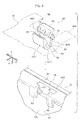
- a catching groove 56 that an operator catches with for example a finger when opening the memory cover 50, and a lock mechanism 60 that retains the memory cover 50 in a state positioned in the closed position, are provided to the case front-rear direction other end portion 50C (rear end portion) of the memory cover 50.
- the lock mechanism 60 is disposed in a rectangular shaped cutout 58 formed in the other end portion 50C of the memory cover 50.
- the lock mechanism 60 includes a grip portion 62 that grips a leading end portion 90A of a flat head screwdriver 90 (see Fig. 6A ), described later.
- the grip portion 62 is formed with a U-shaped cross-section shape that configures a projection out from the memory cover 50 towards the opening 40 inner side, and includes a first grip tab 62A and a second grip tab 62B pair that mutually face each other, and a bottom wall portion 62C that connects together the first grip tab 62A and the second grip tab 62B.
- the first grip tab 62A extends out from a front side edge portion 58A of the cutout 58 towards the inner side of the opening 40 (the opening bottom section 40L side).
- the second grip tab 62B is disposed on the opposite side with respect to the first grip tab 62A to the opening portion 40A (see Fig. 4 ) of the previously described memory cover 50 that acts as the pivot axis.
- the second grip tab 62B is disposed on the opposite side with respect to the first grip tab 62A to the memory cover 50 opening direction.
- a pair of projection portions 66 are respectively provided to the first grip tab 62A and the second grip tab 62B so as to project out into the insertion groove 64.
- the second grip tab 62B resiliently deforms in the direction to move away from the first grip tab 62A (the arrow T direction) when the leading end portion 90A of the flat head screwdriver 90 is inserted between the pair of projection portions 66.
- the leading end portion 90A of the flat head screwdriver 90 is also gripped from both sides between the pair of projection portions 66 due to the rebound force of the resiliently deformed second grip tab 62B.
- One of the projection portions 66 that projects out from the second grip tab 62B is positioned, with respect to the other of the projection portions 66 that projects out from the first grip tab 62A, on the insertion opening 64A side of the insertion groove 64. Consequently, a configuration is achieved in which a larger moment acts on the second grip tab 62B than on the first grip tab 62A when the leading end portion 90A of the flat head screwdriver 90 is inserted between the pair of projection portions 66.
- the second grip tab 62B is accordingly readily resiliently deformed in the direction to move away from the first grip tab 62A when the leading end portion 90A of the flat head screwdriver 90 is inserted between the pair of projection portions 66.
- a flat portion 66C that extends out in a direction orthogonal to the insertion direction of the flat head screwdriver 90 is formed to each of the projection portions 66 on the opposite side to the insertion opening 64A.
- the leading end portion 90A of the flat head screwdriver 90 accordingly catches on the flat portion 66C of each of the projection portions 66 when the leading end portion 90A is withdrawn from between the pair of projection portions 66, rendering it difficult for the leading end portion 90A of the flat head screwdriver 90 to be pulled out from between the pair of projection portions 66.
- An engaging portion 68 is furthermore provided on the opposite side of the second grip tab 62B to the first grip tab 62A.
- An engaged portion 48 is also provided to an inside wall portion 46 of the opening 40, disposed at the opening 40 inner side with respect to the engaging portion 68. Consequently, when the second grip tab 62B is resiliently deformed in the direction to move away from the first grip tab 62A, the engaging portion 68 accordingly engages with the engaged portion 48 in the flat head screwdriver 90 insertion direction in a configuration in which displacement of the second grip tab 62B towards the opening 40 inner side is restricted.
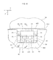
- claw portions 70 serving as examples of anchor portions are respectively provided on the two width direction sides of the second grip tab 62B.
- a pair of restriction wall portions 80 is provided at positions facing towards the claw portions 70 as an example of a pair of restriction portions on the opening bottom section 40L.
- the pair of restriction wall portions 80 are, as illustrated in Fig. 9A , disposed with respect to the claw portions 70 so as to be on the first grip tab 62A side in an anchored state of the claw portions 70 to engaged portions 82, described later.
- the claw portions 70 make contact with the restriction wall portions 80, in a configuration that restricts resilient deformation of the second grip tab 62B.
- the engaged portions 82 are provided to each of the restriction wall portions 80 so as to extend out from the restriction wall portions 80 towards the opposite side to the first grip tab 62A.
- the engaged portions 82 are disposed on the memory cover 50 opening direction (the arrow R1 direction) side with respect to the claw portions 70.
- the claw portions 70 are accordingly anchored by the engaged portions 82 when the memory cover 50 attempts to pivot in the opening direction. Pivoting of the memory cover 50 in the opening direction is thereby restricted, and in a configuration that holds the memory cover 50 in a state positioned in the closed position.
- the claw portions 70 are moved in the direction to move away from the first grip tab 62A accompanying resilient deformation of the second grip tab 62B. More specifically, the claw portions 70 move from an anchored state anchored to the engaged portions 82 (the position illustrated in Fig. 9A ) towards a released position (the position illustrated in Fig. 9B ) in which the anchored state to the engaged portions 82 is released. The anchored state of the claw portions 70 to the engaged portions 82 is thereby released. Movement of the claw portions 70 to the released position enables the claw portions 70 to move through an attachment-detachment opening 84 formed between the engaged portions 82 and the engaged portion 48, towards the memory cover 50 opening direction.
- Fig. 9A illustrates a state in which the claw portions 70 of the lock mechanism 60 are anchored in the memory cover 50 opening direction by the engaged portions 82 of the fixed side casing 30, and the memory cover 50 is held in the closed position in the opening 40.
- the leading end portion 90A of the flat head screwdriver 90 is inserted into the insertion groove 64 formed in the grip portion 62 of the lock mechanism 60.
- the leading end portion 90A of the flat head screwdriver 90 is thereby gripped between the pair of projection portions 66 that project out towards the insertion groove 64 respectively from the first grip tab 62A and the second grip tab 62B, and the second grip tab 62B is resiliently deformed in the direction to move away from the first grip tab 62A (the arrow T direction).
- the claw portions 70 move in the direction to move away from the first grip tab 62A. Namely, the claw portions 70 move from the anchor position anchored to the engaged portions 82 towards the released position in which the anchored state to the engaged portions 82 is released. The anchored state of the claw portions 70 to the engaged portions 82 is thereby released, enabling the claw portions 70 to move through the attachment-detachment opening 84 towards the memory cover 50 opening direction.
- the memory cover 50 In order to close the memory cover 50, in a state in which the leading end portion 90A of the flat head screwdriver 90 has been withdrawn from the grip portion 62, the memory cover 50 is pivoted towards the closed direction (the arrow R2 direction) about the opening portion 40A hooked into by the pair of hook portions 52. Sloping faces 70A (see Fig. 5 ) formed to the claw portions 70 of the lock mechanism 60 then press against edge portions of the attachment-detachment opening 84, and the claw portions 70 are inserted into the attachment-detachment opening 84 as the second grip tab 62B is resiliently deformed in the direction to move away from the first grip tab 62A.
- the second grip tab 62B rebounds in the direction to approach the first grip tab 62A.
- the claw portions 70 move from the released position towards the anchored position accompanying the rebound of the second grip tab 62B, and the claw portions 70 are anchored with respect to the engaged portions 82.
- the memory cover 50 is accordingly held in a state positioned in the closed position.
- the claw portions 70 are moved from the anchored position, in which they are anchored to the engaged portions 82, to the released position, in which the anchored state to the engaged portions 82 is released, by inserting the leading end portion 90A of the flat head screwdriver 90 into the insertion groove 64.
- the leading end portion 90A of the flat head screwdriver 90 is gripped between the pair of the first grip tab 62A and the second grip tab 62B.
- the memory cover 50 can accordingly be opened by pulling the flat head screwdriver 90 upwards towards the memory cover 50 opening direction. The effort of the opening operation of the memory cover 50 is accordingly reduced.
- the projection portions 66 are respectively provided to the first grip tab 62A and the second grip tab 62B.
- the gripping force on the leading end portion 90A is increased by the leading end portion 90A of the flat head screwdriver 90 being gripped by the projection portions 66.
- the sloping portion 66B is formed to each of the projection portions 66 on the insertion opening 64A side of the insertion groove 64, so as to slope towards the opposite side to the insertion opening 64A (towards the opening bottom section 40L side) on progression towards the projection direction leading end portion 66A side.
- the leading end portion 90A of the flat head screwdriver 90 can thus be inserted into the insertion groove 64, and the leading end portion 90A of the flat head screwdriver 90 is guided along the sloping portions 66B of the respective projection portions 66 between the pair of leading end portions 66A of the projection portions 66.
- the leading end portion 90A of the flat head screwdriver 90 can accordingly be inserted easily between the pair of projection portions 66.
- one of the projection portions 66 that projects out from the second grip tab 62B is positioned with respect to the other of the projection portions 66 that projects out from the first grip tab 62A on the insertion opening 64A side of the insertion groove 64.
- a larger moment accordingly acts on the second grip tab 62B than on the first grip tab 62A when the leading end portion 90A of the flat head screwdriver 90 is inserted between the pair of projection portions 66.
- the second grip tab 62B is accordingly readily resiliently deformed in the direction to move away from the first grip tab 62A, and the insertion force to insert the leading end portion 90A of the flat head screwdriver 90 between the pair of projection portions 66 is reduced.
- the effort of the opening operation of the memory cover 50 is accordingly reduced even further.
- the flat portions 66C are formed respectively to each of the projection portions 66 on the opposite side to the insertion opening 64A, so as to extend in a direction orthogonal to the flat head screwdriver 90 insertion direction.
- the leading end portion 90A of the flat head screwdriver 90 accordingly readily catches on each of the flat portions 66C of each of the projection portions 66 when the flat head screwdriver 90, whose leading end portion 90A has been inserted between the pair of projection portions 66, is pulled up in the memory cover 50 opening direction.
- the leading end portion 90A of the flat head screwdriver 90 is accordingly suppressed from coming out from the between the pair of projection portions 66 when the memory cover 50 is pulled up in the opening direction by the flat head screwdriver 90.
- the anchored state of the claw portions 70 with respect to the engaged portions 82 is released by causing the second grip tab 62B to resiliently deform with respect to the first grip tab 62A towards the opposite side to the memory cover 50 opening direction.
- the deformation direction of the second grip tab 62B is the opposite direction to the memory cover 50 opening direction. It is accordingly difficult to resiliently deform the second grip tab 62B with the finger of an operator, and then, in a state in which the anchored state of the claw portions 70 with respect to the engaged portions 82 is released, to pivot the memory cover 50 in the opening direction.
- the restriction wall portions 80 are provided to the opening bottom section 40L so as to be disposed on the first grip tab 62A side with respect to the claw portions 70 positioned in the anchored position.
- the claw portions 70 accordingly make contact with the restriction wall portions 80 when for example an operator attempts, such as with their finger, to deform the second grip tab 62B in the direction to approach the first grip tab 62A. Resilient deformation of the second grip tab 62B in the direction to approach the first grip tab 62A is accordingly restricted. Release of the anchored state of the claw portions 70 with respect to the engaged portions 82 can accordingly be suppressed.
- the engaging portion 68 is provided to the second grip tab 62B projecting out towards the opposite side to the first grip tab 62A.
- the engaged portion 48 is also provided to the inside wall portion 46 of the opening 40 so as to be disposed on the opening 40 inner side with respect to the engaging portion 68.
- the memory cover 50 is maintained in the closed position by the claw portions 70 being anchored to the engaged portions 82.
- the number of components can accordingly be reduced in comparison to cases in which the memory cover 50 is fixed to the lower case 34 by for example bolts or screws.
- the projection portions 66 are respectively provided to the first grip tab 62A and the second grip tab 62B, however a projection portion 66 may be provided to only one of the first grip tab 62A or the second grip tab 62B. Moreover, the projection portions 66 may be provided to the first grip tab 62A, or to the second grip tab 62B, or to the first grip tab 62A and the second grip tab 62B, and configuration may be made in which the projection portions 66 are omitted as appropriate.
- the grip portion 62 is formed with a U-shaped cross-section, however the shape of the grip portion 62 may be modified as appropriate. Moreover, the shape, placement and number of portions, such as the claw portions 70, the engaged portions 82 and the restriction wall portions 80 illustrated in the above exemplary embodiment, may be modified as appropriate. Similarly, the shape, placement and number of portions, such as the engaging portion 68 and the engaged portion 48 illustrated in the above exemplary embodiment, may be modified as appropriate. Note that the restriction wall portions 80, the engaging portion 68 and the engaged portion 48 may be provided as appropriate, and configuration may be made in which they are omitted as appropriate.
- the second grip tab 62B is disposed on the opposite side to the opening portion 40A that is the pivot axis of the memory cover 50 with respect to first grip tab 62A
- the second grip tab 62B may be placed on the opening portion 40A side with respect to the first grip tab 62A.
- the lock mechanism 60 is provided to the other end portion 50C of the memory cover 50, there is no limitation thereto.
- the lock mechanism 60 may be provided to the case width direction end portions 50B of the memory cover 50.
- first end portion 50A of the memory cover 50 is detachably attached to the opening portion 40A of the opening 40, there is no limitation thereto.
- the first end portion 50A of the memory cover 50 may be non-detachably attached to the opening portion 40A of the opening 40 through for example a hinge.
- the memory cover 50 serves as a cover
- the cover may be configured as the radiator fin cover 26, or may be configured as a hard disk cover attached to an opening employed for a hard disk drive, serving as an example of a storage device, so as to be capable of opening and closing.
- the flat head screwdriver 90 serves as the insertion member, however there is no limitation thereto.
- the insertion member may, for example, by be configured by any member capable of being inserted into the insertion groove 64 of the lock mechanism 60 to release the anchored state between the claw portions 70 and the engaged portions 82.
- the insertion member is not limited to a general purpose implement such as the flat head screwdriver 90, and a dedicated implement with a shape corresponding to the shape of the grip portion 62 may be employed.
Landscapes
- Engineering & Computer Science (AREA)
- Theoretical Computer Science (AREA)
- Computer Hardware Design (AREA)
- General Engineering & Computer Science (AREA)
- Physics & Mathematics (AREA)
- Human Computer Interaction (AREA)
- General Physics & Mathematics (AREA)
- Mathematical Physics (AREA)
- Mechanical Engineering (AREA)
- Microelectronics & Electronic Packaging (AREA)
- Casings For Electric Apparatus (AREA)
Applications Claiming Priority (1)
| Application Number | Priority Date | Filing Date | Title |
|---|---|---|---|
| JP2012170534A JP6089482B2 (ja) | 2012-07-31 | 2012-07-31 | 筐体、及び筐体を備えた電子装置 |
Publications (3)
| Publication Number | Publication Date |
|---|---|
| EP2693293A2 true EP2693293A2 (de) | 2014-02-05 |
| EP2693293A3 EP2693293A3 (de) | 2016-04-27 |
| EP2693293B1 EP2693293B1 (de) | 2017-05-17 |
Family
ID=48325446
Family Applications (1)
| Application Number | Title | Priority Date | Filing Date |
|---|---|---|---|
| EP13166691.9A Not-in-force EP2693293B1 (de) | 2012-07-31 | 2013-05-06 | Gehäuse und elektronische Vorrichtung |
Country Status (4)
| Country | Link |
|---|---|
| US (1) | US9113561B2 (de) |
| EP (1) | EP2693293B1 (de) |
| JP (1) | JP6089482B2 (de) |
| CN (1) | CN103582363B (de) |
Cited By (1)
| Publication number | Priority date | Publication date | Assignee | Title |
|---|---|---|---|---|
| TWI769496B (zh) * | 2020-08-06 | 2022-07-01 | 佳世達科技股份有限公司 | 顯示螢幕 |
Families Citing this family (3)
| Publication number | Priority date | Publication date | Assignee | Title |
|---|---|---|---|---|
| KR20170076382A (ko) * | 2015-12-24 | 2017-07-04 | 삼성전자주식회사 | 디스플레이 장치 |
| CN109542164B (zh) * | 2017-09-22 | 2022-04-26 | 联想(新加坡)私人有限公司 | 对接装置以及电子设备 |
| US11357120B2 (en) | 2020-09-11 | 2022-06-07 | Phoenix Contact Development and Manufacturing, Inc. | Electrical component enclosure and method of use |
Citations (3)
| Publication number | Priority date | Publication date | Assignee | Title |
|---|---|---|---|---|
| JPS58184878U (ja) | 1982-05-31 | 1983-12-08 | 東亜特殊電機株式会社 | 機器ケ−スの開閉蓋 |
| JPS649180A (en) | 1987-06-29 | 1989-01-12 | Toshiba Corp | Case for transporting apparatus |
| JP2002216728A (ja) | 2001-01-23 | 2002-08-02 | Matsushita Electric Ind Co Ltd | 電子機器筐体 |
Family Cites Families (18)
| Publication number | Priority date | Publication date | Assignee | Title |
|---|---|---|---|---|
| JPS58184878A (ja) | 1982-04-22 | 1983-10-28 | Konishiroku Photo Ind Co Ltd | 画像情報記録媒体及び記録読出し方法 |
| GB2182019B (en) * | 1985-10-25 | 1990-02-28 | Burroughs Corp | Improved equipment enclosure |
| JPH0416342Y2 (de) * | 1986-08-13 | 1992-04-13 | ||
| JPH073562Y2 (ja) * | 1988-03-28 | 1995-01-30 | 松下電工株式会社 | 電磁接触器 |
| DE4009001A1 (de) * | 1990-03-21 | 1990-08-02 | Warwick Bass Guitars Inh Hans | Saiteninstrument, insbesondere bass- oder elektrogitarre |
| JP2818913B2 (ja) * | 1991-05-28 | 1998-10-30 | 松下電工株式会社 | ツイストロック機構 |
| US5634675A (en) * | 1995-07-28 | 1997-06-03 | Dialer & Business Electronic Co., Ltd. | Latch for battery compartment |
| US5808863A (en) * | 1996-12-10 | 1998-09-15 | Dell U.S.A., L.P. | Computer system having quick-detachable recyclable parts and method |
| JP3954222B2 (ja) * | 1998-11-04 | 2007-08-08 | 株式会社岡村製作所 | 間仕切装置における側部カバーへの取付具の取付構造 |
| US6394300B1 (en) * | 2000-04-17 | 2002-05-28 | Daniel F. Bosy | Lock for compartment cover |
| JP4555521B2 (ja) * | 2001-09-18 | 2010-10-06 | 富士通株式会社 | 情報処理装置及び着脱ユニット |
| TWM242976U (en) * | 2003-08-06 | 2004-09-01 | Quanta Comp Inc | Detachable and rotatable door cover assembly |
| WO2006112022A1 (ja) * | 2005-04-15 | 2006-10-26 | Fujitsu Limited | 折り畳み可能な筐体のロック装置及びそれを有する電子機器 |
| TWM278795U (en) * | 2005-06-08 | 2005-10-21 | Inventec Corp | Push-type buckle device |
| JP4249736B2 (ja) * | 2005-09-20 | 2009-04-08 | Necディスプレイソリューションズ株式会社 | カバーの取り付け構造 |
| JP4935747B2 (ja) * | 2008-04-23 | 2012-05-23 | 富士電機機器制御株式会社 | 回路遮断器の端子カバー |
| TWM394671U (en) * | 2010-08-06 | 2010-12-11 | Gemtek Technology Co Ltd | Buckling structure |
| CN102421266A (zh) * | 2011-08-19 | 2012-04-18 | 鸿富锦精密工业(深圳)有限公司 | 具有顶出机构的电子设备 |
-
2012
- 2012-07-31 JP JP2012170534A patent/JP6089482B2/ja not_active Expired - Fee Related
-
2013
- 2013-05-06 EP EP13166691.9A patent/EP2693293B1/de not_active Not-in-force
- 2013-05-28 US US13/903,439 patent/US9113561B2/en not_active Expired - Fee Related
- 2013-05-31 CN CN201310213460.8A patent/CN103582363B/zh not_active Expired - Fee Related
Patent Citations (3)
| Publication number | Priority date | Publication date | Assignee | Title |
|---|---|---|---|---|
| JPS58184878U (ja) | 1982-05-31 | 1983-12-08 | 東亜特殊電機株式会社 | 機器ケ−スの開閉蓋 |
| JPS649180A (en) | 1987-06-29 | 1989-01-12 | Toshiba Corp | Case for transporting apparatus |
| JP2002216728A (ja) | 2001-01-23 | 2002-08-02 | Matsushita Electric Ind Co Ltd | 電子機器筐体 |
Cited By (1)
| Publication number | Priority date | Publication date | Assignee | Title |
|---|---|---|---|---|
| TWI769496B (zh) * | 2020-08-06 | 2022-07-01 | 佳世達科技股份有限公司 | 顯示螢幕 |
Also Published As
| Publication number | Publication date |
|---|---|
| US9113561B2 (en) | 2015-08-18 |
| CN103582363B (zh) | 2017-03-01 |
| US20140036422A1 (en) | 2014-02-06 |
| EP2693293B1 (de) | 2017-05-17 |
| JP2014029647A (ja) | 2014-02-13 |
| CN103582363A (zh) | 2014-02-12 |
| EP2693293A3 (de) | 2016-04-27 |
| JP6089482B2 (ja) | 2017-03-08 |
Similar Documents
| Publication | Publication Date | Title |
|---|---|---|
| EP2693293B1 (de) | Gehäuse und elektronische Vorrichtung | |
| US9376845B2 (en) | Hinge device and housing | |
| US10734777B2 (en) | Circuit board actuator system | |
| EP0592090A1 (de) | Sicherheitsmechanismus für tragbaren Rechner | |
| US6683785B1 (en) | Mobile rack for hard disk drives | |
| CN101981758B (zh) | 连接器端口 | |
| US20030035265A1 (en) | Latch assembly that facilitates the insertion and removal of a battery module from an electronic device | |
| CN103809688B (zh) | 装拆机构、安装装置、电子设备 | |
| CN101660555A (zh) | 卡扣装置及使用该卡扣装置的电子设备 | |
| US7374438B2 (en) | Electronic apparatus incorporating latch mechanism | |
| US20050270727A1 (en) | Loading cartridge latch structure | |
| TWI399183B (zh) | A slide fastener with an automatic stop device | |
| JP4555521B2 (ja) | 情報処理装置及び着脱ユニット | |
| US8863376B2 (en) | Connector removing jig and connector removing method using the same | |
| US20160349793A1 (en) | Expansion device and electronic apparatus | |
| CN2785021Y (zh) | 笔记本电脑机壳 | |
| TW201826069A (zh) | 電子模組退出機構及其可攜式電子裝置 | |
| KR100433513B1 (ko) | 노트북 컴퓨터의 하드디스크 드라이브 조립체 | |
| TW201429421A (zh) | 拉鏈用滑件 | |
| CN207069150U (zh) | 线盒 | |
| JP5074463B2 (ja) | 遊技機 | |
| JP2002339635A (ja) | 蝶 番 | |
| JP2009163927A (ja) | 開閉蓋のロック装置 | |
| JP2014206777A (ja) | デバイス収容装置 | |
| CN219711270U (zh) | 一种一体式卡扣反弹器 |
Legal Events
| Date | Code | Title | Description |
|---|---|---|---|
| AK | Designated contracting states |
Kind code of ref document: A2 Designated state(s): AL AT BE BG CH CY CZ DE DK EE ES FI FR GB GR HR HU IE IS IT LI LT LU LV MC MK MT NL NO PL PT RO RS SE SI SK SM TR |
|
| AX | Request for extension of the european patent |
Extension state: BA ME |
|
| PUAI | Public reference made under article 153(3) epc to a published international application that has entered the european phase |
Free format text: ORIGINAL CODE: 0009012 |
|
| PUAL | Search report despatched |
Free format text: ORIGINAL CODE: 0009013 |
|
| AK | Designated contracting states |
Kind code of ref document: A3 Designated state(s): AL AT BE BG CH CY CZ DE DK EE ES FI FR GB GR HR HU IE IS IT LI LT LU LV MC MK MT NL NO PL PT RO RS SE SI SK SM TR |
|
| AX | Request for extension of the european patent |
Extension state: BA ME |
|
| RIC1 | Information provided on ipc code assigned before grant |
Ipc: E05C 19/06 20060101ALI20160323BHEP Ipc: G06F 1/16 20060101AFI20160323BHEP Ipc: H05K 5/02 20060101ALI20160323BHEP Ipc: H04M 1/02 20060101ALI20160323BHEP |
|
| 17P | Request for examination filed |
Effective date: 20160926 |
|
| RBV | Designated contracting states (corrected) |
Designated state(s): AL AT BE BG CH CY CZ DE DK EE ES FI FR GB GR HR HU IE IS IT LI LT LU LV MC MK MT NL NO PL PT RO RS SE SI SK SM TR |
|
| REG | Reference to a national code |
Ref country code: DE Ref legal event code: R079 Ref document number: 602013021165 Country of ref document: DE Free format text: PREVIOUS MAIN CLASS: G06F0001160000 Ipc: G06F0003010000 |
|
| GRAP | Despatch of communication of intention to grant a patent |
Free format text: ORIGINAL CODE: EPIDOSNIGR1 |
|
| RIC1 | Information provided on ipc code assigned before grant |
Ipc: G06F 1/16 20060101ALI20161123BHEP Ipc: G06F 3/01 20060101AFI20161123BHEP Ipc: H05K 5/02 20060101ALI20161123BHEP Ipc: E05C 19/06 20060101ALI20161123BHEP Ipc: H04M 1/02 20060101ALI20161123BHEP |
|
| INTG | Intention to grant announced |
Effective date: 20161206 |
|
| GRAS | Grant fee paid |
Free format text: ORIGINAL CODE: EPIDOSNIGR3 |
|
| GRAA | (expected) grant |
Free format text: ORIGINAL CODE: 0009210 |
|
| AK | Designated contracting states |
Kind code of ref document: B1 Designated state(s): AL AT BE BG CH CY CZ DE DK EE ES FI FR GB GR HR HU IE IS IT LI LT LU LV MC MK MT NL NO PL PT RO RS SE SI SK SM TR |
|
| REG | Reference to a national code |
Ref country code: GB Ref legal event code: FG4D |
|
| REG | Reference to a national code |
Ref country code: CH Ref legal event code: EP |
|
| REG | Reference to a national code |
Ref country code: IE Ref legal event code: FG4D |
|
| REG | Reference to a national code |
Ref country code: AT Ref legal event code: REF Ref document number: 895034 Country of ref document: AT Kind code of ref document: T Effective date: 20170615 |
|
| REG | Reference to a national code |
Ref country code: DE Ref legal event code: R096 Ref document number: 602013021165 Country of ref document: DE |
|
| REG | Reference to a national code |
Ref country code: NL Ref legal event code: MP Effective date: 20170517 |
|
| REG | Reference to a national code |
Ref country code: LT Ref legal event code: MG4D |
|
| REG | Reference to a national code |
Ref country code: AT Ref legal event code: MK05 Ref document number: 895034 Country of ref document: AT Kind code of ref document: T Effective date: 20170517 |
|
| PG25 | Lapsed in a contracting state [announced via postgrant information from national office to epo] |
Ref country code: LT Free format text: LAPSE BECAUSE OF FAILURE TO SUBMIT A TRANSLATION OF THE DESCRIPTION OR TO PAY THE FEE WITHIN THE PRESCRIBED TIME-LIMIT Effective date: 20170517 Ref country code: FI Free format text: LAPSE BECAUSE OF FAILURE TO SUBMIT A TRANSLATION OF THE DESCRIPTION OR TO PAY THE FEE WITHIN THE PRESCRIBED TIME-LIMIT Effective date: 20170517 Ref country code: GR Free format text: LAPSE BECAUSE OF FAILURE TO SUBMIT A TRANSLATION OF THE DESCRIPTION OR TO PAY THE FEE WITHIN THE PRESCRIBED TIME-LIMIT Effective date: 20170818 Ref country code: AT Free format text: LAPSE BECAUSE OF FAILURE TO SUBMIT A TRANSLATION OF THE DESCRIPTION OR TO PAY THE FEE WITHIN THE PRESCRIBED TIME-LIMIT Effective date: 20170517 Ref country code: HR Free format text: LAPSE BECAUSE OF FAILURE TO SUBMIT A TRANSLATION OF THE DESCRIPTION OR TO PAY THE FEE WITHIN THE PRESCRIBED TIME-LIMIT Effective date: 20170517 Ref country code: NO Free format text: LAPSE BECAUSE OF FAILURE TO SUBMIT A TRANSLATION OF THE DESCRIPTION OR TO PAY THE FEE WITHIN THE PRESCRIBED TIME-LIMIT Effective date: 20170817 Ref country code: ES Free format text: LAPSE BECAUSE OF FAILURE TO SUBMIT A TRANSLATION OF THE DESCRIPTION OR TO PAY THE FEE WITHIN THE PRESCRIBED TIME-LIMIT Effective date: 20170517 |
|
| PG25 | Lapsed in a contracting state [announced via postgrant information from national office to epo] |
Ref country code: RS Free format text: LAPSE BECAUSE OF FAILURE TO SUBMIT A TRANSLATION OF THE DESCRIPTION OR TO PAY THE FEE WITHIN THE PRESCRIBED TIME-LIMIT Effective date: 20170517 Ref country code: NL Free format text: LAPSE BECAUSE OF FAILURE TO SUBMIT A TRANSLATION OF THE DESCRIPTION OR TO PAY THE FEE WITHIN THE PRESCRIBED TIME-LIMIT Effective date: 20170517 Ref country code: SE Free format text: LAPSE BECAUSE OF FAILURE TO SUBMIT A TRANSLATION OF THE DESCRIPTION OR TO PAY THE FEE WITHIN THE PRESCRIBED TIME-LIMIT Effective date: 20170517 Ref country code: PL Free format text: LAPSE BECAUSE OF FAILURE TO SUBMIT A TRANSLATION OF THE DESCRIPTION OR TO PAY THE FEE WITHIN THE PRESCRIBED TIME-LIMIT Effective date: 20170517 Ref country code: BG Free format text: LAPSE BECAUSE OF FAILURE TO SUBMIT A TRANSLATION OF THE DESCRIPTION OR TO PAY THE FEE WITHIN THE PRESCRIBED TIME-LIMIT Effective date: 20170817 Ref country code: IS Free format text: LAPSE BECAUSE OF FAILURE TO SUBMIT A TRANSLATION OF THE DESCRIPTION OR TO PAY THE FEE WITHIN THE PRESCRIBED TIME-LIMIT Effective date: 20170917 Ref country code: LV Free format text: LAPSE BECAUSE OF FAILURE TO SUBMIT A TRANSLATION OF THE DESCRIPTION OR TO PAY THE FEE WITHIN THE PRESCRIBED TIME-LIMIT Effective date: 20170517 |
|
| PG25 | Lapsed in a contracting state [announced via postgrant information from national office to epo] |
Ref country code: DK Free format text: LAPSE BECAUSE OF FAILURE TO SUBMIT A TRANSLATION OF THE DESCRIPTION OR TO PAY THE FEE WITHIN THE PRESCRIBED TIME-LIMIT Effective date: 20170517 Ref country code: CZ Free format text: LAPSE BECAUSE OF FAILURE TO SUBMIT A TRANSLATION OF THE DESCRIPTION OR TO PAY THE FEE WITHIN THE PRESCRIBED TIME-LIMIT Effective date: 20170517 Ref country code: EE Free format text: LAPSE BECAUSE OF FAILURE TO SUBMIT A TRANSLATION OF THE DESCRIPTION OR TO PAY THE FEE WITHIN THE PRESCRIBED TIME-LIMIT Effective date: 20170517 Ref country code: SK Free format text: LAPSE BECAUSE OF FAILURE TO SUBMIT A TRANSLATION OF THE DESCRIPTION OR TO PAY THE FEE WITHIN THE PRESCRIBED TIME-LIMIT Effective date: 20170517 Ref country code: RO Free format text: LAPSE BECAUSE OF FAILURE TO SUBMIT A TRANSLATION OF THE DESCRIPTION OR TO PAY THE FEE WITHIN THE PRESCRIBED TIME-LIMIT Effective date: 20170517 |
|
| REG | Reference to a national code |
Ref country code: DE Ref legal event code: R097 Ref document number: 602013021165 Country of ref document: DE |
|
| PG25 | Lapsed in a contracting state [announced via postgrant information from national office to epo] |
Ref country code: IT Free format text: LAPSE BECAUSE OF FAILURE TO SUBMIT A TRANSLATION OF THE DESCRIPTION OR TO PAY THE FEE WITHIN THE PRESCRIBED TIME-LIMIT Effective date: 20170517 Ref country code: SM Free format text: LAPSE BECAUSE OF FAILURE TO SUBMIT A TRANSLATION OF THE DESCRIPTION OR TO PAY THE FEE WITHIN THE PRESCRIBED TIME-LIMIT Effective date: 20170517 |
|
| REG | Reference to a national code |
Ref country code: FR Ref legal event code: PLFP Year of fee payment: 6 |
|
| PLBE | No opposition filed within time limit |
Free format text: ORIGINAL CODE: 0009261 |
|
| STAA | Information on the status of an ep patent application or granted ep patent |
Free format text: STATUS: NO OPPOSITION FILED WITHIN TIME LIMIT |
|
| 26N | No opposition filed |
Effective date: 20180220 |
|
| PG25 | Lapsed in a contracting state [announced via postgrant information from national office to epo] |
Ref country code: SI Free format text: LAPSE BECAUSE OF FAILURE TO SUBMIT A TRANSLATION OF THE DESCRIPTION OR TO PAY THE FEE WITHIN THE PRESCRIBED TIME-LIMIT Effective date: 20170517 |
|
| REG | Reference to a national code |
Ref country code: CH Ref legal event code: PL |
|
| REG | Reference to a national code |
Ref country code: DE Ref legal event code: R081 Ref document number: 602013021165 Country of ref document: DE Owner name: FUJITSU CLIENT COMPUTING LIMITED, KAWASAKI-SHI, JP Free format text: FORMER OWNER: FUJITSU LIMITED, KAWASAKI-SHI, KANAGAWA, JP Ref country code: DE Ref legal event code: R082 Ref document number: 602013021165 Country of ref document: DE Representative=s name: HASELTINE LAKE KEMPNER LLP, DE Ref country code: DE Ref legal event code: R082 Ref document number: 602013021165 Country of ref document: DE Representative=s name: HL KEMPNER PATENTANWALT, RECHTSANWALT, SOLICIT, DE Ref country code: DE Ref legal event code: R082 Ref document number: 602013021165 Country of ref document: DE Representative=s name: HASELTINE LAKE LLP, DE |
|
| REG | Reference to a national code |
Ref country code: BE Ref legal event code: MM Effective date: 20180531 |
|
| PG25 | Lapsed in a contracting state [announced via postgrant information from national office to epo] |
Ref country code: MC Free format text: LAPSE BECAUSE OF FAILURE TO SUBMIT A TRANSLATION OF THE DESCRIPTION OR TO PAY THE FEE WITHIN THE PRESCRIBED TIME-LIMIT Effective date: 20170517 |
|
| REG | Reference to a national code |
Ref country code: IE Ref legal event code: MM4A |
|
| PG25 | Lapsed in a contracting state [announced via postgrant information from national office to epo] |
Ref country code: CH Free format text: LAPSE BECAUSE OF NON-PAYMENT OF DUE FEES Effective date: 20180531 Ref country code: LI Free format text: LAPSE BECAUSE OF NON-PAYMENT OF DUE FEES Effective date: 20180531 |
|
| REG | Reference to a national code |
Ref country code: GB Ref legal event code: 732E Free format text: REGISTERED BETWEEN 20190207 AND 20190213 |
|
| PG25 | Lapsed in a contracting state [announced via postgrant information from national office to epo] |
Ref country code: LU Free format text: LAPSE BECAUSE OF NON-PAYMENT OF DUE FEES Effective date: 20180506 |
|
| PG25 | Lapsed in a contracting state [announced via postgrant information from national office to epo] |
Ref country code: IE Free format text: LAPSE BECAUSE OF NON-PAYMENT OF DUE FEES Effective date: 20180506 |
|
| PG25 | Lapsed in a contracting state [announced via postgrant information from national office to epo] |
Ref country code: BE Free format text: LAPSE BECAUSE OF NON-PAYMENT OF DUE FEES Effective date: 20180531 |
|
| PGFP | Annual fee paid to national office [announced via postgrant information from national office to epo] |
Ref country code: FR Payment date: 20190410 Year of fee payment: 7 |
|
| PGFP | Annual fee paid to national office [announced via postgrant information from national office to epo] |
Ref country code: GB Payment date: 20190501 Year of fee payment: 7 |
|
| PG25 | Lapsed in a contracting state [announced via postgrant information from national office to epo] |
Ref country code: MT Free format text: LAPSE BECAUSE OF NON-PAYMENT OF DUE FEES Effective date: 20180506 |
|
| PG25 | Lapsed in a contracting state [announced via postgrant information from national office to epo] |
Ref country code: TR Free format text: LAPSE BECAUSE OF FAILURE TO SUBMIT A TRANSLATION OF THE DESCRIPTION OR TO PAY THE FEE WITHIN THE PRESCRIBED TIME-LIMIT Effective date: 20170517 |
|
| PG25 | Lapsed in a contracting state [announced via postgrant information from national office to epo] |
Ref country code: PT Free format text: LAPSE BECAUSE OF FAILURE TO SUBMIT A TRANSLATION OF THE DESCRIPTION OR TO PAY THE FEE WITHIN THE PRESCRIBED TIME-LIMIT Effective date: 20170517 Ref country code: HU Free format text: LAPSE BECAUSE OF FAILURE TO SUBMIT A TRANSLATION OF THE DESCRIPTION OR TO PAY THE FEE WITHIN THE PRESCRIBED TIME-LIMIT; INVALID AB INITIO Effective date: 20130506 |
|
| PG25 | Lapsed in a contracting state [announced via postgrant information from national office to epo] |
Ref country code: CY Free format text: LAPSE BECAUSE OF FAILURE TO SUBMIT A TRANSLATION OF THE DESCRIPTION OR TO PAY THE FEE WITHIN THE PRESCRIBED TIME-LIMIT Effective date: 20170517 Ref country code: MK Free format text: LAPSE BECAUSE OF NON-PAYMENT OF DUE FEES Effective date: 20170517 |
|
| PG25 | Lapsed in a contracting state [announced via postgrant information from national office to epo] |
Ref country code: AL Free format text: LAPSE BECAUSE OF FAILURE TO SUBMIT A TRANSLATION OF THE DESCRIPTION OR TO PAY THE FEE WITHIN THE PRESCRIBED TIME-LIMIT Effective date: 20170517 |
|
| PGFP | Annual fee paid to national office [announced via postgrant information from national office to epo] |
Ref country code: DE Payment date: 20200422 Year of fee payment: 8 |
|
| REG | Reference to a national code |
Ref country code: DE Ref legal event code: R082 Ref document number: 602013021165 Country of ref document: DE Representative=s name: HL KEMPNER PATENTANWALT, RECHTSANWALT, SOLICIT, DE |
|
| GBPC | Gb: european patent ceased through non-payment of renewal fee |
Effective date: 20200506 |
|
| PG25 | Lapsed in a contracting state [announced via postgrant information from national office to epo] |
Ref country code: FR Free format text: LAPSE BECAUSE OF NON-PAYMENT OF DUE FEES Effective date: 20200531 Ref country code: GB Free format text: LAPSE BECAUSE OF NON-PAYMENT OF DUE FEES Effective date: 20200506 |
|
| REG | Reference to a national code |
Ref country code: DE Ref legal event code: R119 Ref document number: 602013021165 Country of ref document: DE |
|
| PG25 | Lapsed in a contracting state [announced via postgrant information from national office to epo] |
Ref country code: DE Free format text: LAPSE BECAUSE OF NON-PAYMENT OF DUE FEES Effective date: 20211201 |