EP2693250B1 - Wide-angle projecting optical system - Google Patents
Wide-angle projecting optical system Download PDFInfo
- Publication number
- EP2693250B1 EP2693250B1 EP13178782.2A EP13178782A EP2693250B1 EP 2693250 B1 EP2693250 B1 EP 2693250B1 EP 13178782 A EP13178782 A EP 13178782A EP 2693250 B1 EP2693250 B1 EP 2693250B1
- Authority
- EP
- European Patent Office
- Prior art keywords
- lens
- optical system
- image
- imaging optical
- denoted
- Prior art date
- Legal status (The legal status is an assumption and is not a legal conclusion. Google has not performed a legal analysis and makes no representation as to the accuracy of the status listed.)
- Active
Links
Images


Classifications
-
- G—PHYSICS
- G02—OPTICS
- G02B—OPTICAL ELEMENTS, SYSTEMS OR APPARATUS
- G02B3/00—Simple or compound lenses
-
- G—PHYSICS
- G02—OPTICS
- G02B—OPTICAL ELEMENTS, SYSTEMS OR APPARATUS
- G02B13/00—Optical objectives specially designed for the purposes specified below
- G02B13/06—Panoramic objectives; So-called "sky lenses" including panoramic objectives having reflecting surfaces
-
- G—PHYSICS
- G02—OPTICS
- G02B—OPTICAL ELEMENTS, SYSTEMS OR APPARATUS
- G02B13/00—Optical objectives specially designed for the purposes specified below
- G02B13/22—Telecentric objectives or lens systems
-
- G—PHYSICS
- G09—EDUCATION; CRYPTOGRAPHY; DISPLAY; ADVERTISING; SEALS
- G09G—ARRANGEMENTS OR CIRCUITS FOR CONTROL OF INDICATING DEVICES USING STATIC MEANS TO PRESENT VARIABLE INFORMATION
- G09G5/00—Control arrangements or circuits for visual indicators common to cathode-ray tube indicators and other visual indicators
- G09G5/10—Intensity circuits
Definitions
- the present invention relates to an imaging optical system such as an imaging lens or a projector projection lens, and more particularly, to an imaging lens which is appropriate for a wide-angle lens having a wide angle of view.
- a wide-angle lens having a wide angle of view is used.
- a wide-angle lens can be used for an apparatus where a distance between a reduction-side imaging plane and a lens end closest to the reduction-side imaging plane is long.
- a single-lens reflex camera or a projector having a color combining system For such applications, a wide-angle lens will typically use a retrofocus-type lens unit.
- the retrofocus-type lens unit is a lens unit with a lens having a strong negative refractive power disposed nearer to an enlargement-side imaging plane than a stop.
- the reduction-side imaging plane side is referred to as the reduction-side; and the enlargement-side imaging plane side is referred to the enlargement-side.
- the first lens unit in the lens unit discussed in the English Abstract of Japanese Patent Application Laid-Open No. 04-356008 forms a reduced image of the object as an intermediate image by a reduction optical system.
- the second lens unit is configured as a relay system which forms the intermediate image on the image plane (an imaging plane of an image sensor). Accordingly, a back focus of the first lens unit is shortened, so that the diameter of the enlargement-side lens of the first lens unit is reduced.
- the lens unit discussed in U.S. Patent Application Publication No. 2005/0117123 is a projection lens for a projector, which forms an image obtained by a light modulation element as an intermediate image and enlarges the intermediate image to project the enlarged image onto a projection receiving surface. Therefore, similarly to the English Abstract of Japanese Patent Application Laid-Open No. 04-356008 , the diameter of the enlargement-side lens of the first lens unit is also reduced.
- the lens unit discussed in the English Abstract of Japanese Patent Application Laid-Open No. 04-356008 is a fisheye lens, and large distortion remains on a final image plane. Therefore, the lens unit is not appropriate for a wide-angle lens for general picture photographing or a projection lens for a projector, where distortion needs to be sufficiently corrected.
- the optical system is constructed of, in order from an object side thereof, an objective lens group Ob having positive refracting power, a primary image formation plane formed by the objective lens group Ob and relay lens group R1 having positive refracting power.
- a field stop FS is positioned at or near the primary image formation plane, and a condition h/f o >1.8 is satisfied where to is the focal length of the objective lens group Ob, and h is the diameter of an image circle on the primary image-formation plane.
- the present invention is directed to an imaging optical system which forms an intermediate image, the imaging optical system having a reduced size while sufficiently correcting distortion.
- an imaging optical system as specified in claims 1 to 12.
- a projection-type image display apparatus as specified in claims 13 and 14.
- an image pickup apparatus as specified in claim 15.
- an imaging optical system which forms an intermediate image, the imaging optical system having a reduced size while sufficiently correcting distortion, and a projection-type image display apparatus and an image pickup apparatus using the imaging optical system.
- Fig. 1 is a cross-sectional diagram illustrating a configuration including an imaging lens (i.e. an imaging optical system) according to a first embodiment of the present invention.
- the imaging optical system is a projection optical system, which is designed for a projector (i.e. for a projection-type image display apparatus).
- the imaging optical system is a wide-angle lens which projects light beams modulated by a liquid crystal panel 5 (a light modulation element) onto a screen (not illustrated) (a projection receiving surface).
- the left side of Fig. 1 is an enlargement side, and the right side thereof is a reduction side.
- the screen surface represents an enlargement-side imaging plane
- the liquid crystal panel 5 is represents a reduction-side imaging plane.
- an enlargement-side imaging plane is at a position where an image formed by the light modulation element (the liquid crystal panel) is projected.
- the enlargement-side imaging plane is at a position of an object to be imaged.
- the reduction-side imaging plane is the position where the light modulation element (a liquid crystal panel) is provided.
- the reduction-side imaging plane is the position where the image pickup element, like, for example, a CCD, is provided.
- the wide-angle lens according to the present embodiment comprises 20 lenses in total.
- a prism glass 4 having no refractive power is disposed between a lens L20 closest to the reduction side and the liquid crystal panel 5.
- the prism glass 4 is used for color composition in the projector.
- the dot-dashed line indicates the optical axis of the wide-angle lens.
- An in-lens conjugate point 3 (intermediate image point) is located on the optical axis between a tenth lens L10 and an eleventh lens L11. With respect to the in-lens conjugate point 3 as a division point, the first lens L1 through the tenth lens L10 constitute the first lens unit 1, and the eleventh lens L11 through the final lens L20 constitute the second lens unit 2.
- the first lens unit 1 is configured to make the screen (an enlargement-side imaging plane) and the in-lens conjugate point 3 conjugate to each other.
- the second lens unit 2 is configured to make the in-lens conjugate point 3 and the liquid crystal panel 5 (a reduction-side imaging plane) conjugate to each other. If the liquid crystal panel 5 is set as a reference, the first lens unit 1 and the second lens unit 2 are configured to make the liquid crystal panel 5 and the screen conjugate to each other, and thus, the enlargement-side imaging plane can be called an enlargement-side conjugate plane. Conversely, if the screen is set as a reference, the reduction-side imaging plane can be called a reduction-side conjugate plane.
- a numerical example of the present embodiment is listed as Numerical Example 1 as follows.
- a surface number is a number uniquely designated to each lens surface in order from the enlargement side;
- R is a radius of curvature of each lens surface,
- d is a surface distance, and
- nd and ⁇ d are a refractive index and an Abbe number, respectively, of a glass material at the d-line (587.56 nm).
- the lens surface with the symbol "*" attached to the right side of the surface number denotes that the lens surface has an aspherical shape according to the function described below, and coefficients thereof are listed in the numerical example.
- a coordinate y is a coordinate in the radial direction when the surface apex of the lens surface is set as a reference and a coordinate x is a coordinate in the optical axis direction when the surface apex of the lens surface is set as a reference.
- the object distance is infinite.
- x y 2 / R / 1 + 1 ⁇ 1 + K * y 2 / R 2 12 + Ay 4 + By 6 + Cy 8 + Dy 10 + Ey 12 + Fy 14
- a focal length of the entire optical system of the wide-angle lens is denoted by an absolute value
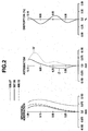
- Fig. 2 illustrates longitudinal aberration graphs representing an image forming performance of the wide-angle lens according to the present embodiment.
- a spherical aberration graph, an astigmatism graph, and a distortion graph are illustrated from the left side of the figure.
- a solid line indicates aberration at the d-line (587.56 nm)
- a broken line indicates aberration at the F-line (486.13 nm)
- a dotted line indicates aberration at the C-line (656.27 nm).
- the horizontal axis denotes a defocus amount, and the scale thereof is -0 . 15 to +0.15 [mm].
- a solid line indicates curvature of field of a sagittal image plane
- a dotted line indicates curvature of field of a meridional image plane.
- the horizontal axis is the same as that of the spherical aberration graph.
- the scale of the horizontal axis is -0.5 to +0.5 [%].
- Fig. 2 it can be understood that distortion is corrected well. In addition, spherical aberration and astigmatism are also corrected well.
- Fig. 3 illustrates longitudinal aberration graphs at the in-lens conjugate point 3 according to the present embodiment.
- the view point is the same as that of Fig. 2 , but the scale is different from that of Fig. 2 .
- the scale of the horizontal axis of spherical aberration and astigmatism is -1.0 to +1.0 [mm] ; and the scale of the horizontal axis of distortion is -5. 0 to +5.0 [%]. It can be understood from Fig. 3 that large curvature of field and large distortion remain at the in-lens conjugate point 3. On the other hand, it can be understood that over-correction is made with respect to axial chromatic aberration.
- the lens closest to the enlargement side of the second lens unit 2, which is a relay lens unit, is configured as a negative lens, and aberration opposite to the remaining aberration is allowed to occur, so that the aberration is cancelled. Therefore, good image forming performance illustrated in Fig. 2 is obtained in the final image plane.
- curvature of field and distortion are allowed to remain at the in-lens conjugate point 3, so that a lens for aberration correction of the first lens unit 1 does not need to be installed. Therefore, the wide-angle lens according to the present embodiment can be configured with a small number of lenses. In addition, it is possible to miniaturize the wide-angle lens according to the present embodiment in the optical axis direction.
- the diameter of the lens for distortion correction does not need to be large. Therefore, the diameter of the enlargement-side lens can be greatly reduced. In addition, the distance between the most-reduction-side lens surface and the liquid crystal panel 5 can be shortened.
- the correction of aberration of the intermediate image formed at the in-lens conjugate point 3 is performed by the second lens unit 2.
- negative distortion greatly occurs.
- the second lens unit 2 needs to generate strong positive distortion.
- the wide-angle lens has a wider angle of view, or although the image height is high
- the above-described effect can be obtained by arranging a surface having strong negative refractive power to be disposed at the first refractive surface sf of the enlargement side of the negative lens at the side (enlargement side) closest to the in-lens conjugate point 3 of the second lens unit 2.
- the surface having strong negative refractive power has a function of bending (bouncing) the light beam which may be bent toward an inner side of the first lens unit 1 greatly to an outer side thereof and a function of bending the light beam having a particularly high image height greatly to the outer side. Therefore, high-order positive distortion can be generated.
- the wide-angle lens according to the present embodiment is configured to include a first optical unit having positive refractive power which forms an intermediate image and a second optical unit having positive refractive power which forms the intermediate image on the image plane.
- a lens disposed closest to the enlargement, side of the second optical unit is a negative lens, it is possible to sufficiently correct distortion and to provide a miniaturized imaging lens.
- the wide-angle lens according to the present embodiment satisfies the following condition: 0.0 ⁇ fF / fR ⁇ 0.8
- the wide-angle lens may satisfy the following condition: 0.0 ⁇ fF / fR ⁇ 0.5
- the first refractive surface sf can satisfy any one of the following conditions: ⁇ 5.00 ⁇ f 1 / fR ⁇ ⁇ 0.05 0.0 ⁇ f 1 / f ⁇ 20.0 ⁇ 12.0 ⁇ f 1 / fF ⁇ 0.0 0.1 ⁇ r / f ⁇ 3.0 ⁇ 1.5 ⁇ r / fR 1 ⁇ n ⁇ 1 ⁇ ⁇ 0.5
- the condition (1a) is the ratio of the focal length f1 of the negative lens L11 disposed closest to the enlargement side of the second lens unit 2 to the focal length fR of the second lens unit 2.
- the condition (2a) is the ratio of the focal length f1 to the focal length
- the condition (3a) is the ratio of the focal length f1 to the focal length fF of the first lens unit 1.
- the condition (4a) is the ratio of the radius of curvature r of the first refractive surface sf of the enlargement side of the negative lens L11 disposed closest to the enlargement side of the second lens unit 2 to the focal length
- the condition (5a) is the ratio of a refractive power r/(n-1) of the first refractive surface sf of the second lens unit 2 to the focal length fR1 of a first group of the second lens unit 2.
- n is a refractive index of the negative lens L11.
- the first group of the second lens unit 2 denotes a lens or a lens group disposed at the enlargement side with respect to the largest lens surface distance in the second lens unit 2.
- any one of the following conditions can be satisfied: ⁇ 3.00 ⁇ f 1 / fR ⁇ ⁇ 0.10 1.0 ⁇ f 1 / f ⁇ 10.0 ⁇ 9.0 ⁇ f 1 / fF ⁇ ⁇ 2.0 0.5 ⁇ r / f ⁇ 2.0 ⁇ 1.4 ⁇ r / fR 1 ⁇ n ⁇ 1 ⁇ ⁇ 0.6
- off-axis principal rays incident on the first refractive surface sf may be set to converge at the reduction side.
- a converging light flux may be incident on the negative lens L11. Accordingly, it is possible to allow high-order positive distortion to more effectively occur, and it is possible to suppress an increase in diameter of the enlargement side lens of the second lens unit 2.
- a positive lens L12 is disposed at the reduction side of the negative lens L11 having the first refractive surface sf without another negative lens interposed therebetween, and the positive lens L12 may be a meniscus lens having a shape convex toward the reduction side. Accordingly, while distortion occurring at the first refractive surface sf remains, the diverged rays can be returned to the direction where the rays are to converge.
- the focal length of the negative lens L11 having the refractive surface sf is denoted by f1 and the focal length of the positive lens L12 is denoted by f2
- the following condition (6a) may be satisfied: ⁇ 1.00 ⁇ f 1 / f 2 ⁇ ⁇ 0.05
- condition (6b) may be satisfied: ⁇ 0.80 ⁇ f 1 / f 2 ⁇ ⁇ 0.10
- the focal length of the positive lens L12 is too greatly increased in comparison to the focal length of the negative lens L11 (the refractive power of the positive lens becomes weak in comparison to the negative lens), so that the effect of allowing the rays of the positive lens L12 to converge cannot be obtained.
- the numeric value is larger than the upper limit value, the effect of distortion intentionally occurring at the negative lens L11 cannot be obtained.
- the distance between the reduction-side surface of the negative lens L11 having the refractive surface sf and the enlargement side surface of the positive lens L12 may be an air distance.
- the negative lens L11 and the positive lens L12 can be adjacent to each other.
- the second lens unit 2 can have a magnification close to the unit magnification if possible.
- the reason is as follows. If the second lens unit has the unit magnification, the paths of off-axis principal rays become symmetric at the enlargement side and the reduction side of an edge portion of a stop or a lens substantially functioning as a stop, so that off-axis aberration such as coma or curvature of field can be easily corrected.
- a cemented lens SL1 obtained by cementing three lens L6, L7, and L8 is disposed in the first lens unit 1.
- axial chromatic aberration greatly occurs in comparison to the lens unit where imaging is performed once.
- a three-lens element cemented lens obtained by cementing positive, negative, and positive lenses in this order from the enlargement side is used. This configuration is very effective for reducing axial chromatic aberration.
- the negative lens L7 when a three-lens cemented lens is used in the first lens unit, the negative lens L7 may be configured by using a high dispersion glass, and the positive lenses L6 and L8 may be configured by using a low dispersion glass.
- the glass material of the negative lens L7 has lower Abbe number (higher dispersion) than the glass material of the positive lenses L6 and L8. Accordingly, axial chromatic aberration is effectively reduced.
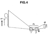
- Fig. 4 is a diagram illustrating shifting (moving) of a projection image 47 projected on a screen when the wide-angle lens according to the present embodiment is used as a projection lens PL of a projection-type image display apparatus.
- the projection-type image display apparatus is configured to include a driving unit (not illustrated) which moves the projection lens PL in a direction having a component perpendicular to the optical axis of the projection lens to shift the projection position of the projection image 47 projected on the screen.
- the first lens unit 1 or the second lens unit 2 is not individually moved, but the entire optical system of the lens units is shifted.
- the moving direction of the projection lens PL is opposite to the moving direction of the projection image. Accordingly, the projection image can be appropriately shifted.
- the shifting direction of the liquid crystal panel 46 (a light modulation element) is the same as the shifting direction of the projection image 47.
- Fig. 5 is a cross-sectional diagram illustrating a configuration of a wide-angle lens according to a second embodiment of the present invention.
- the wide-angle lens is designed by considering the use as an imaging lens (imaging optical system) of an image pickup apparatus such as a single-lens reflex camera.
- the first lens unit 1 is configured to include a first lens L1 through an eleventh lens L11.
- the second lens unit 2 is configured to include a twelfth lens L12 through a final lens L20.
- the lens corresponding to the negative lens L11 according to the first embodiment is a lens L12.
- the left side of Fig. 5 is the enlargement side, and the right side thereof is the reduction side.
- the wide-angle lens illustrated in Fig. 5 is configured to include a first lens unit 1 (first optical unit) and a second lens unit 2 (second optical unit) in this order from the enlargement side.
- the object plane is an enlargement-side imaging plane; and the image plane is a reduction-side imaging plane.
- the image pickup apparatus include an image sensor.
- an image plane is an imaging plane of the image sensor, which receives light from a subject (object) through the wide-angle lens and photo-electrically converts the received light to form image data.
- the first lens unit 1 is configured to make the object plane and an in-lens conjugate point 3 conjugate to each other.
- the second lens unit 2 is configured to make the in-lens conjugate point 3 and the image sensor conjugate to each other.
- the back focus region of the image pickup apparatus is a movable region of a flip-up mirror (quick-return mirror) and a prism glass is not disposed there.
- a numerical example of the present embodiment is listed as Numerical Example 2. The object distance is infinite.
- the imaging lens according to the second embodiment is also configured to satisfy the condition (A1) described in the first embodiment, and the lens disposed closest to the enlargement side of the second lens unit is configured as a negative lens. Therefore, it is possible to sufficiently correct distortion and to provide a miniaturized imaging lens.
- the imaging lens according to the second embodiment is also configured to satisfy the desirable conditions described in the first embodiment, and thus, similar effects obtained in the conditions of the first embodiment can be also obtained.
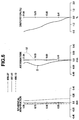
- Fig. 6 illustrates longitudinal aberration graphs representing image forming performance according to the present embodiment. Similarly to the first embodiment, a particularly wide angle and high performance can be obtained.
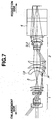
- Fig. 7 is a cross-sectional diagram illustrating a configuration of a wide-angle lens according to a third embodiment of the present invention.
- the back focus is increased by allowing the angle of view to be slightly suppressed and allowing the F-number to be smaller.
- a numerical example of the present embodiment is listed as Numerical Example 3. The object distance is infinite.
- the lens corresponding to the negative lens L11 according to the first embodiment is a lens L9.
- the wide-angle lens according to the third embodiment is also configured to satisfy the condition (A1) described in the first embodiment, and the lens disposed closest to the enlargement side of the second lens unit is configured as a negative lens. Therefore, it is possible to sufficiently correct distortion and to provide a miniaturized imaging lens.
- the wide-angle lens according to the third embodiment is also configured to satisfy the desired conditions described in the first embodiment, and thus, similar effects obtained in the conditions of the first embodiment can be also obtained (Numerical Example 3)
- Fig. 8 illustrates longitudinal aberration graphs representing image forming performance according to the present embodiment.
- a three-lens cemented lens SL2 is disposed in the second lens unit according to the present embodiment.
- the three-lens cemented lens SL2 is configured so that a lower-dispersion negative lens is interposed between higher-dispersion positive lenses.
- the three-lens cemented lens SL2 has a strong achromatic effect.
- the three-lens cemented lens SL2 can be configured to include, in order from the enlargement side, in this order from the enlargement side, a biconcave negative lens, a biconvex positive lens, and a negative meniscus lens having a concave surface facing the enlargement side.
- Fig. 9 is a cross-sectional view illustrating a configuration of a wide-angle lens according to a fourth embodiment of the present invention.
- the fourth embodiment is different from the first embodiment in that focusing is performed by moving a sixth lens 91, which is the sixth lens from the enlargement side of the second lens unit 2, as a focus lens.
- the sixth lens 91 has a weak negative refractive power. During focusing from an infinitely distant point to a closest point, the sixth lens 91 is moved along the optical axis from the reduction side to the enlargement side.
- the focus lens, which is moved for performing focusing may a single lens or a lens group (focus group) including a plurality of lenses.
- a numerical example of the present embodiment is listed as Numerical Example 4.
- the letter "z" affixed to the numeric value of the surface distance denotes that the surface distance varies according to a change in object distance.
- the numeric value of the surface distance according to a change in the object distance is listed as Numerical Example 4.
- the lens corresponding to the negative lens L11 according to the first embodiment is a lens L11.
- the wide-angle lens according to the fourth embodiment is also configured to satisfy the condition (A1) described in the first embodiment, and the lens disposed closest to the enlargement side of the second lens unit is configured as a negative lens. Therefore, it is possible to sufficiently correct distortion and to provide a miniaturized imaging lens.
- the wide-angle lens according to the fourth embodiment is also configured to satisfy the desirable conditions described in the first embodiment, and thus, similar effects obtained in the conditions of the first embodiment can be also obtained.
- Paths of light rays are greatly changed according to a subject distance (object distance) in the case of a particularly-wide-angle lens as in the present embodiment, or according to a projection distance in the case of a projection lens. Therefore, there is a problem in that various aberrations are changed due to focusing. In order to perform focusing while suppressing a change in aberration if possible, a plurality of lenses needs to be moved during focusing, that is, floating needs to be performed. However, there is still a problem in that the change in aberration cannot be completely suppressed.
- the change in aberration is still large in the method for moving the entire first lens unit or the entire second lens unit.
- the first lens unit 1 and the second lens unit 2 generate aberration in opposite directions to perform the aberration correction. Therefore, if the first lens unit 1 and the second lens unit 2 are independently moved, the change in aberration cannot be suppressed.
- the first lens unit 1 is a retrofocus-type lens unit
- the change in aberration may be suppressed to some degree by using the method for simultaneously moving a plurality of lens groups, which is called floating as described above.
- the sufficient distortion correction is an object of the present embodiment.
- the change in aberration including distortion can be effectively suppressed by using the method for performing focusing by moving a portion of lenses of the second lens unit 2.
- the second lens unit 2 it is desirable to move a lens having a weak refractive power in the vicinity of the light ray with the lowest image height. The reason is as follows. If the lens located at the position where the height of a light ray is low is allowed to be moved, the change in various off-axis aberrations due to the movement is suppressed. Therefore, the change in curvature of field or distortion can be suppressed to be almost zero. In other words, focusing is performed by moving a portion of lenses of the second lens unit 2, so that it is possible to greatly solve the problem of changes in aberration due to focusing changes.
- f fo a focal length of the focus lens (entire optical system of the focus lens group in the case of a plurality of lenses)
- f fo a focal length of the focus lens
- condition (7a) the following condition may be satisfied: 20.0 ⁇ f fo / f ⁇ 100.0
- the focal length f fo of the focus lens is -394.8 [mm], and
- 57.3.
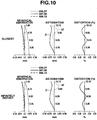
- Fig. 10 illustrates longitudinal aberration graphs representing image forming performance according to the present embodiment. It can be understood that a change in various aberrations can be suppressed down to an infinitesimal level over the range of a closest point to an infinitely distant point.
- a focus lens group including a plurality of lenses may be moveable. In this case, if the focus lens described in the present embodiment is configured as a focus lens group, the same effect as that in the present embodiment can be obtained.
- Fig. 11 is a cross-sectional view illustrating a configuration of a wide-angle lens according to a fifth embodiment of the present invention.
- the fifth embodiment is different from the third embodiment in that a zoom lens is configured as a five-group configuration including five lens groups which are moved with the distance being changed during zooming.
- the first lens group B1 and the fifth lens group B5 are configured to be stationary during zooming
- the second lens group B2, the third lens group B3, and the fourth lens group B4 are configured to move during zooming.
- a numerical example of the present embodiment is listed as Numerical Example 5.
- the letter "z" affixed to the numeric value of the surface distance denotes that the surface distance is changed in accordance with zooming.
- the numeric value of the surface distance according to zooming is listed as Numerical Example 5.
- the lens corresponding to the negative lens L11 according to the first embodiment is a lens L9.
- the wide-angle lens according to the fifth embodiment is also configured to satisfy the condition (A1) described in the first embodiment, and the lens disposed closest to the enlargement side of the second lens unit (the third lens group B3) is configured as a negative lens. Therefore, it is possible to sufficiently correct distortion and to provide a miniaturized imaging lens.
- the wide-angle lens according to the fifth embodiment is also configured to satisfy the desirable conditions described in the first embodiment, and thus, similar effects obtained in the conditions of the first embodiment can be also obtained.
- the zooming function is mainly performed by the second lens group B2 and the fourth lens group B4.
- Fig. 12 illustrates longitudinal aberration graphs representing image forming performance according to the present embodiment. It is understood that basic image performance is maintained even when zooming is performed.
Landscapes
- Physics & Mathematics (AREA)
- General Physics & Mathematics (AREA)
- Optics & Photonics (AREA)
- Engineering & Computer Science (AREA)
- Computer Hardware Design (AREA)
- Theoretical Computer Science (AREA)
- Lenses (AREA)
- Projection Apparatus (AREA)
Priority Applications (2)
| Application Number | Priority Date | Filing Date | Title |
|---|---|---|---|
| EP15199627.9A EP3026476B1 (en) | 2012-07-31 | 2013-07-31 | Wide-angle projecting optical system |
| EP20153803.0A EP3686641B1 (en) | 2012-07-31 | 2013-07-31 | Imaging optical system |
Applications Claiming Priority (1)
| Application Number | Priority Date | Filing Date | Title |
|---|---|---|---|
| JP2012169755A JP5871743B2 (ja) | 2012-07-31 | 2012-07-31 | 結像光学系、及びそれを用いた投射型画像表示装置、撮像装置 |
Related Child Applications (3)
| Application Number | Title | Priority Date | Filing Date |
|---|---|---|---|
| EP20153803.0A Division EP3686641B1 (en) | 2012-07-31 | 2013-07-31 | Imaging optical system |
| EP15199627.9A Division-Into EP3026476B1 (en) | 2012-07-31 | 2013-07-31 | Wide-angle projecting optical system |
| EP15199627.9A Division EP3026476B1 (en) | 2012-07-31 | 2013-07-31 | Wide-angle projecting optical system |
Publications (2)
| Publication Number | Publication Date |
|---|---|
| EP2693250A1 EP2693250A1 (en) | 2014-02-05 |
| EP2693250B1 true EP2693250B1 (en) | 2016-06-29 |
Family
ID=48914102
Family Applications (3)
| Application Number | Title | Priority Date | Filing Date |
|---|---|---|---|
| EP13178782.2A Active EP2693250B1 (en) | 2012-07-31 | 2013-07-31 | Wide-angle projecting optical system |
| EP15199627.9A Active EP3026476B1 (en) | 2012-07-31 | 2013-07-31 | Wide-angle projecting optical system |
| EP20153803.0A Active EP3686641B1 (en) | 2012-07-31 | 2013-07-31 | Imaging optical system |
Family Applications After (2)
| Application Number | Title | Priority Date | Filing Date |
|---|---|---|---|
| EP15199627.9A Active EP3026476B1 (en) | 2012-07-31 | 2013-07-31 | Wide-angle projecting optical system |
| EP20153803.0A Active EP3686641B1 (en) | 2012-07-31 | 2013-07-31 | Imaging optical system |
Country Status (4)
| Country | Link |
|---|---|
| US (1) | US9041848B2 (enExample) |
| EP (3) | EP2693250B1 (enExample) |
| JP (1) | JP5871743B2 (enExample) |
| CN (1) | CN103576289B (enExample) |
Families Citing this family (50)
| Publication number | Priority date | Publication date | Assignee | Title |
|---|---|---|---|---|
| EP2899581B1 (en) * | 2012-09-20 | 2017-08-23 | Nittoh Inc. | Zoom lens system and image-capturing device |
| JP5924542B2 (ja) * | 2013-02-15 | 2016-05-25 | 輝 矢部 | 撮像光学系 |
| US9529181B2 (en) * | 2013-10-10 | 2016-12-27 | Nittoh Kogaku K.K. | Zoom lens system and imaging apparatus |
| JP6253437B2 (ja) | 2014-02-14 | 2017-12-27 | キヤノン株式会社 | 結像光学系及びそれを有する画像投射装置 |
| JP6305098B2 (ja) * | 2014-02-19 | 2018-04-04 | キヤノン株式会社 | ズーム光学系及びそれを有する画像投射装置 |
| US9910251B2 (en) * | 2014-03-19 | 2018-03-06 | Nittoh Inc. | Lens system and imaging apparatus having a lens at each side of an intermediate image which move in synchronization during focusing |
| CN104977634B (zh) * | 2014-04-03 | 2016-09-28 | 奇景光电股份有限公司 | 透镜阵列 |
| US10133030B2 (en) * | 2014-06-17 | 2018-11-20 | Samsung Electro-Mechanics Co., Ltd. | High resolution lens module |
| KR101719874B1 (ko) | 2014-06-17 | 2017-03-24 | 삼성전기주식회사 | 렌즈 모듈 |
| JP6535947B2 (ja) * | 2015-01-16 | 2019-07-03 | 株式会社タムロン | 観察用光学系及びそれを備えた撮像装置 |
| JP6578662B2 (ja) * | 2015-02-05 | 2019-09-25 | コニカミノルタ株式会社 | 投影光学系及びプロジェクター |
| JP6352832B2 (ja) | 2015-02-25 | 2018-07-04 | 富士フイルム株式会社 | 投写用光学系および投写型表示装置 |
| JP6342828B2 (ja) * | 2015-02-25 | 2018-06-13 | 富士フイルム株式会社 | 投写用光学系および投写型表示装置 |
| JP6342827B2 (ja) * | 2015-02-25 | 2018-06-13 | 富士フイルム株式会社 | 投写用光学系および投写型表示装置 |
| US9606425B2 (en) * | 2015-06-19 | 2017-03-28 | Canon Kabushiki Kaisha | Imaging optical system, optical apparatus and image projection apparatus |
| JP6198862B2 (ja) * | 2016-01-14 | 2017-09-20 | キヤノン株式会社 | 結像光学系、及びそれを用いた投射型画像表示装置、撮像装置 |
| JP6029159B1 (ja) * | 2016-05-13 | 2016-11-24 | 株式会社タムロン | 観察光学系、観察撮像装置、観察撮像システム、結像レンズ系及び観察光学系の調整方法 |
| JP6872692B2 (ja) * | 2016-05-13 | 2021-05-19 | パナソニックIpマネジメント株式会社 | 結像光学系及び画像投写装置 |
| JP6692694B2 (ja) * | 2016-05-25 | 2020-05-13 | 富士フイルム株式会社 | 結像光学系、投写型表示装置、および、撮像装置 |
| JP6570477B2 (ja) * | 2016-05-25 | 2019-09-04 | 富士フイルム株式会社 | 結像光学系、投写型表示装置、および撮像装置 |
| JP6576299B2 (ja) * | 2016-05-25 | 2019-09-18 | 富士フイルム株式会社 | 結像光学系、撮像装置、および投写型表示装置 |
| JP6579998B2 (ja) | 2016-05-25 | 2019-09-25 | 富士フイルム株式会社 | 結像光学系、投写型表示装置、および、撮像装置 |
| JP6595405B2 (ja) * | 2016-05-25 | 2019-10-23 | 富士フイルム株式会社 | 結像光学系、投写型表示装置、および、撮像装置 |
| CN107450166A (zh) | 2016-06-01 | 2017-12-08 | 精工爱普生株式会社 | 投射光学系统和投射型图像显示装置 |
| JP6534371B2 (ja) * | 2016-08-30 | 2019-06-26 | 富士フイルム株式会社 | ズームレンズ、撮像装置、および投写型表示装置 |
| JP6587591B2 (ja) | 2016-08-30 | 2019-10-09 | 富士フイルム株式会社 | ズームレンズ、投写型表示装置、および、撮像装置 |
| JP6639358B2 (ja) * | 2016-08-30 | 2020-02-05 | 富士フイルム株式会社 | ズームレンズ、投写型表示装置、および、撮像装置 |
| JP2018036390A (ja) | 2016-08-30 | 2018-03-08 | 富士フイルム株式会社 | 広角レンズ、投写型表示装置、および、撮像装置 |
| JP6570493B2 (ja) | 2016-08-30 | 2019-09-04 | 富士フイルム株式会社 | ズームレンズ、投写型表示装置、および撮像装置 |
| JP6556106B2 (ja) * | 2016-08-30 | 2019-08-07 | 富士フイルム株式会社 | ズームレンズ、投写型表示装置、および、撮像装置 |
| JP6625028B2 (ja) | 2016-08-30 | 2019-12-25 | 富士フイルム株式会社 | ズームレンズ、撮像装置、および投写型表示装置 |
| JP2018085552A (ja) * | 2016-11-21 | 2018-05-31 | セイコーエプソン株式会社 | プロジェクターシステム |
| JP6836141B2 (ja) | 2016-12-09 | 2021-02-24 | セイコーエプソン株式会社 | 投写光学系および投写型画像表示装置 |
| US10816780B2 (en) | 2017-03-29 | 2020-10-27 | Panasonic Intellectual Property Management Co., Ltd. | Lens system, and image projection apparatus and imaging apparatus that include the same |
| JP7019961B2 (ja) | 2017-04-20 | 2022-02-16 | コニカミノルタ株式会社 | 投影光学系及び投影装置 |
| JP6735716B2 (ja) * | 2017-08-17 | 2020-08-05 | 富士フイルム株式会社 | 結像光学系、投写型表示装置、及び撮像装置 |
| JP6939469B2 (ja) | 2017-11-27 | 2021-09-22 | セイコーエプソン株式会社 | 投写光学系および投写型画像表示装置 |
| JP7154769B2 (ja) * | 2018-01-29 | 2022-10-18 | キヤノン株式会社 | 結像光学系および画像投射装置 |
| JP6847071B2 (ja) * | 2018-03-28 | 2021-03-24 | 富士フイルム株式会社 | 結像光学系、投写型表示装置、および撮像装置 |
| EP3916460A4 (en) * | 2019-01-25 | 2022-03-09 | Panasonic Intellectual Property Management Co., Ltd. | OPTICAL SYSTEM, IMAGE PROJECTION DEVICE AND IMAGE DEVICE |
| US12092800B2 (en) | 2019-06-24 | 2024-09-17 | Circle Optics, Inc. | Opto-mechanics of panoramic capture devices with abutting cameras |
| WO2021133843A1 (en) | 2019-12-23 | 2021-07-01 | Circle Optics, Inc. | Mounting systems for multi-camera imagers |
| JP6791322B2 (ja) * | 2019-08-27 | 2020-11-25 | コニカミノルタ株式会社 | 投影光学系及びプロジェクター |
| JP2021067703A (ja) * | 2019-10-17 | 2021-04-30 | キヤノン株式会社 | 結像光学系およびそれを有する画像投影装置 |
| JP2021076771A (ja) * | 2019-11-12 | 2021-05-20 | キヤノン株式会社 | 結像光学系およびそれを有する画像投影装置 |
| IL295272A (en) * | 2020-02-10 | 2022-10-01 | Circle Optics Inc | Panoramic camera system for enhanced sensing |
| JP7020531B2 (ja) * | 2020-10-29 | 2022-02-16 | コニカミノルタ株式会社 | 投影光学系及びプロジェクター |
| CN116868103A (zh) * | 2021-02-16 | 2023-10-10 | 松下知识产权经营株式会社 | 光学系统、图像投影装置以及摄像装置 |
| CN117355783A (zh) * | 2021-05-10 | 2024-01-05 | 松下知识产权经营株式会社 | 光学系统、图像投影装置以及摄像装置 |
| WO2025142046A1 (ja) * | 2023-12-26 | 2025-07-03 | 株式会社ミツトヨ | 観察光学系および測定装置 |
Family Cites Families (24)
| Publication number | Priority date | Publication date | Assignee | Title |
|---|---|---|---|---|
| JPH07119888B2 (ja) * | 1987-05-08 | 1995-12-20 | 株式会社ニコン | 再結像光学系 |
| JPH04356008A (ja) | 1991-01-24 | 1992-12-09 | Mitsubishi Electric Corp | 赤外線広角レンズ |
| US6094311A (en) | 1996-04-29 | 2000-07-25 | U.S. Precision Lens Inc. | LCD projection lens |
| DE19641656A1 (de) | 1996-10-09 | 1998-04-23 | Zeiss Carl Jena Gmbh | Vorrichtung zum Erzeugen ringförmiger Bilder |
| JP2001023887A (ja) | 1999-07-09 | 2001-01-26 | Nikon Corp | 投影光学系、該光学系を備える投影露光装置及び露光方法 |
| US6476983B2 (en) | 1999-12-07 | 2002-11-05 | Canon Kabushiki Kaisha | Eyepiece lens, objective lens, and optical apparatus having them |
| JP2002014283A (ja) | 2000-06-28 | 2002-01-18 | Fuji Photo Optical Co Ltd | 赤外線ズームレンズまたは赤外線多焦点レンズ、赤外線イメージングシステム、およびパノラマ観察光学系 |
| CA2490012C (en) * | 2002-07-22 | 2009-11-10 | Panavision, Inc. | Zoom lens system |
| JP4345050B2 (ja) | 2003-02-19 | 2009-10-14 | 株式会社ニコン | 超広角レンズ |
| JP2005128286A (ja) | 2003-10-24 | 2005-05-19 | Olympus Corp | 超広角レンズ光学系及びそれを備えた撮像装置と表示装置 |
| JP4734827B2 (ja) | 2003-11-28 | 2011-07-27 | 株式会社日立製作所 | 投写光学ユニット |
| JP4708806B2 (ja) * | 2005-02-07 | 2011-06-22 | 富士フイルム株式会社 | 投写レンズおよびこれを用いた投写型表示装置 |
| US7224535B2 (en) * | 2005-07-29 | 2007-05-29 | Panavision International, L.P. | Zoom lens system |
| JP4864600B2 (ja) * | 2006-08-11 | 2012-02-01 | 富士フイルム株式会社 | 投写型ズームレンズおよび投写型表示装置 |
| JP4924003B2 (ja) | 2006-12-15 | 2012-04-25 | 株式会社ニコン | 広角レンズ、撮像装置、広角レンズの合焦方法 |
| WO2008103851A1 (en) * | 2007-02-21 | 2008-08-28 | Theia Technologies, Llc | Whole system zoom and varifocal lens with intermediate image |
| JP5053680B2 (ja) * | 2007-03-29 | 2012-10-17 | キヤノン株式会社 | 画像投射光学系及び画像投射装置 |
| JP5015739B2 (ja) * | 2007-11-26 | 2012-08-29 | 富士フイルム株式会社 | 投影用ズームレンズおよび投写型表示装置 |
| JP5081049B2 (ja) * | 2008-04-17 | 2012-11-21 | 富士フイルム株式会社 | 投写用ズームレンズおよび投写型表示装置 |
| JP5152854B2 (ja) * | 2008-07-24 | 2013-02-27 | 富士フイルム株式会社 | 投写型可変焦点レンズおよび投写型表示装置 |
| JP2010160478A (ja) * | 2008-12-08 | 2010-07-22 | Fujinon Corp | 投写用ズームレンズおよび投写型表示装置 |
| JP5349938B2 (ja) * | 2008-12-11 | 2013-11-20 | キヤノン株式会社 | ズームレンズ |
| JP5287326B2 (ja) * | 2009-02-16 | 2013-09-11 | セイコーエプソン株式会社 | 投射用ズームレンズ及び投射型画像表示装置 |
| JP5254146B2 (ja) * | 2009-07-29 | 2013-08-07 | 富士フイルム株式会社 | 投写用広角ズームレンズおよび投写型表示装置 |
-
2012
- 2012-07-31 JP JP2012169755A patent/JP5871743B2/ja active Active
-
2013
- 2013-07-26 US US13/951,707 patent/US9041848B2/en active Active
- 2013-07-30 CN CN201310323656.2A patent/CN103576289B/zh active Active
- 2013-07-31 EP EP13178782.2A patent/EP2693250B1/en active Active
- 2013-07-31 EP EP15199627.9A patent/EP3026476B1/en active Active
- 2013-07-31 EP EP20153803.0A patent/EP3686641B1/en active Active
Also Published As
| Publication number | Publication date |
|---|---|
| CN103576289B (zh) | 2016-05-25 |
| EP3686641B1 (en) | 2024-03-06 |
| EP2693250A1 (en) | 2014-02-05 |
| CN103576289A (zh) | 2014-02-12 |
| EP3026476A1 (en) | 2016-06-01 |
| EP3686641A1 (en) | 2020-07-29 |
| JP2014029392A (ja) | 2014-02-13 |
| US20140036142A1 (en) | 2014-02-06 |
| EP3026476B1 (en) | 2020-04-01 |
| US9041848B2 (en) | 2015-05-26 |
| JP5871743B2 (ja) | 2016-03-01 |
Similar Documents
| Publication | Publication Date | Title |
|---|---|---|
| EP2693250B1 (en) | Wide-angle projecting optical system | |
| JP5441377B2 (ja) | 単焦点光学系及びそれを有する撮像装置 | |
| US8223439B2 (en) | Optical system and image pickup apparatus having the optical system | |
| EP2090916B1 (en) | Retrofocus objective using lenses exhibiting relative partial dispersion | |
| US8854747B2 (en) | Optical system and image pickup apparatus including the same | |
| EP2309308A1 (en) | Optical system and optical device including the same | |
| US20070291377A1 (en) | Zoom lens system and image pickup apparatus including the same | |
| CN101770067A (zh) | 光学系统和包含光学系统的光学装置 | |
| JP2007328163A (ja) | ズームレンズ及びそれを有する画像投射装置 | |
| US8477428B2 (en) | Zoom lens and image pickup apparatus having the zoom lens | |
| US11480776B2 (en) | Zoom lens and imaging apparatus having the same | |
| JP5294622B2 (ja) | 光学系及びそれを有する光学機器 | |
| JP4989079B2 (ja) | ズームレンズ及びそれを有する画像投射装置 | |
| US8248703B2 (en) | Zoom lens and optical apparatus having the zoom lens | |
| JP3619117B2 (ja) | ズームレンズ及びそれを用いた光学機器 | |
| US8503101B2 (en) | Zoom lens and image pickup apparatus equipped with zoom lens | |
| JP6198862B2 (ja) | 結像光学系、及びそれを用いた投射型画像表示装置、撮像装置 | |
| US8964303B2 (en) | Zoom lens and image pickup apparatus having the same | |
| US20230114901A1 (en) | Zoom lens and image pickup apparatus having the same | |
| US6768595B2 (en) | Five-group zoom lens and projection display device including it | |
| US11960066B2 (en) | Zoom lens and image pickup apparatus | |
| KR100726777B1 (ko) | 줌 렌즈 광학계 | |
| JPH1068880A (ja) | マクロ機構を有する収差可変光学系 | |
| US20240377614A1 (en) | Optical system and image pickup apparatus |
Legal Events
| Date | Code | Title | Description |
|---|---|---|---|
| AK | Designated contracting states |
Kind code of ref document: A1 Designated state(s): AL AT BE BG CH CY CZ DE DK EE ES FI FR GB GR HR HU IE IS IT LI LT LU LV MC MK MT NL NO PL PT RO RS SE SI SK SM TR |
|
| AX | Request for extension of the european patent |
Extension state: BA ME |
|
| PUAI | Public reference made under article 153(3) epc to a published international application that has entered the european phase |
Free format text: ORIGINAL CODE: 0009012 |
|
| 17P | Request for examination filed |
Effective date: 20140805 |
|
| RBV | Designated contracting states (corrected) |
Designated state(s): AL AT BE BG CH CY CZ DE DK EE ES FI FR GB GR HR HU IE IS IT LI LT LU LV MC MK MT NL NO PL PT RO RS SE SI SK SM TR |
|
| 17Q | First examination report despatched |
Effective date: 20140902 |
|
| GRAP | Despatch of communication of intention to grant a patent |
Free format text: ORIGINAL CODE: EPIDOSNIGR1 |
|
| INTG | Intention to grant announced |
Effective date: 20150803 |
|
| INTG | Intention to grant announced |
Effective date: 20160119 |
|
| GRAS | Grant fee paid |
Free format text: ORIGINAL CODE: EPIDOSNIGR3 |
|
| GRAA | (expected) grant |
Free format text: ORIGINAL CODE: 0009210 |
|
| AK | Designated contracting states |
Kind code of ref document: B1 Designated state(s): AL AT BE BG CH CY CZ DE DK EE ES FI FR GB GR HR HU IE IS IT LI LT LU LV MC MK MT NL NO PL PT RO RS SE SI SK SM TR |
|
| REG | Reference to a national code |
Ref country code: GB Ref legal event code: FG4D |
|
| REG | Reference to a national code |
Ref country code: CH Ref legal event code: EP |
|
| REG | Reference to a national code |
Ref country code: FR Ref legal event code: PLFP Year of fee payment: 4 |
|
| REG | Reference to a national code |
Ref country code: AT Ref legal event code: REF Ref document number: 809539 Country of ref document: AT Kind code of ref document: T Effective date: 20160715 |
|
| REG | Reference to a national code |
Ref country code: IE Ref legal event code: FG4D |
|
| REG | Reference to a national code |
Ref country code: DE Ref legal event code: R096 Ref document number: 602013008871 Country of ref document: DE |
|
| REG | Reference to a national code |
Ref country code: LT Ref legal event code: MG4D |
|
| PG25 | Lapsed in a contracting state [announced via postgrant information from national office to epo] |
Ref country code: NO Free format text: LAPSE BECAUSE OF FAILURE TO SUBMIT A TRANSLATION OF THE DESCRIPTION OR TO PAY THE FEE WITHIN THE PRESCRIBED TIME-LIMIT Effective date: 20160929 Ref country code: FI Free format text: LAPSE BECAUSE OF FAILURE TO SUBMIT A TRANSLATION OF THE DESCRIPTION OR TO PAY THE FEE WITHIN THE PRESCRIBED TIME-LIMIT Effective date: 20160629 Ref country code: LT Free format text: LAPSE BECAUSE OF FAILURE TO SUBMIT A TRANSLATION OF THE DESCRIPTION OR TO PAY THE FEE WITHIN THE PRESCRIBED TIME-LIMIT Effective date: 20160629 |
|
| REG | Reference to a national code |
Ref country code: NL Ref legal event code: MP Effective date: 20160629 |
|
| PG25 | Lapsed in a contracting state [announced via postgrant information from national office to epo] |
Ref country code: GR Free format text: LAPSE BECAUSE OF FAILURE TO SUBMIT A TRANSLATION OF THE DESCRIPTION OR TO PAY THE FEE WITHIN THE PRESCRIBED TIME-LIMIT Effective date: 20160930 Ref country code: NL Free format text: LAPSE BECAUSE OF FAILURE TO SUBMIT A TRANSLATION OF THE DESCRIPTION OR TO PAY THE FEE WITHIN THE PRESCRIBED TIME-LIMIT Effective date: 20160629 Ref country code: LV Free format text: LAPSE BECAUSE OF FAILURE TO SUBMIT A TRANSLATION OF THE DESCRIPTION OR TO PAY THE FEE WITHIN THE PRESCRIBED TIME-LIMIT Effective date: 20160629 Ref country code: RS Free format text: LAPSE BECAUSE OF FAILURE TO SUBMIT A TRANSLATION OF THE DESCRIPTION OR TO PAY THE FEE WITHIN THE PRESCRIBED TIME-LIMIT Effective date: 20160629 Ref country code: SE Free format text: LAPSE BECAUSE OF FAILURE TO SUBMIT A TRANSLATION OF THE DESCRIPTION OR TO PAY THE FEE WITHIN THE PRESCRIBED TIME-LIMIT Effective date: 20160629 Ref country code: HR Free format text: LAPSE BECAUSE OF FAILURE TO SUBMIT A TRANSLATION OF THE DESCRIPTION OR TO PAY THE FEE WITHIN THE PRESCRIBED TIME-LIMIT Effective date: 20160629 |
|
| REG | Reference to a national code |
Ref country code: AT Ref legal event code: MK05 Ref document number: 809539 Country of ref document: AT Kind code of ref document: T Effective date: 20160629 |
|
| PG25 | Lapsed in a contracting state [announced via postgrant information from national office to epo] |
Ref country code: BE Free format text: LAPSE BECAUSE OF NON-PAYMENT OF DUE FEES Effective date: 20160731 |
|
| PG25 | Lapsed in a contracting state [announced via postgrant information from national office to epo] |
Ref country code: IS Free format text: LAPSE BECAUSE OF FAILURE TO SUBMIT A TRANSLATION OF THE DESCRIPTION OR TO PAY THE FEE WITHIN THE PRESCRIBED TIME-LIMIT Effective date: 20161029 Ref country code: IT Free format text: LAPSE BECAUSE OF FAILURE TO SUBMIT A TRANSLATION OF THE DESCRIPTION OR TO PAY THE FEE WITHIN THE PRESCRIBED TIME-LIMIT Effective date: 20160629 Ref country code: CZ Free format text: LAPSE BECAUSE OF FAILURE TO SUBMIT A TRANSLATION OF THE DESCRIPTION OR TO PAY THE FEE WITHIN THE PRESCRIBED TIME-LIMIT Effective date: 20160629 Ref country code: RO Free format text: LAPSE BECAUSE OF FAILURE TO SUBMIT A TRANSLATION OF THE DESCRIPTION OR TO PAY THE FEE WITHIN THE PRESCRIBED TIME-LIMIT Effective date: 20160629 Ref country code: EE Free format text: LAPSE BECAUSE OF FAILURE TO SUBMIT A TRANSLATION OF THE DESCRIPTION OR TO PAY THE FEE WITHIN THE PRESCRIBED TIME-LIMIT Effective date: 20160629 Ref country code: SK Free format text: LAPSE BECAUSE OF FAILURE TO SUBMIT A TRANSLATION OF THE DESCRIPTION OR TO PAY THE FEE WITHIN THE PRESCRIBED TIME-LIMIT Effective date: 20160629 |
|
| PG25 | Lapsed in a contracting state [announced via postgrant information from national office to epo] |
Ref country code: AT Free format text: LAPSE BECAUSE OF FAILURE TO SUBMIT A TRANSLATION OF THE DESCRIPTION OR TO PAY THE FEE WITHIN THE PRESCRIBED TIME-LIMIT Effective date: 20160629 Ref country code: PL Free format text: LAPSE BECAUSE OF FAILURE TO SUBMIT A TRANSLATION OF THE DESCRIPTION OR TO PAY THE FEE WITHIN THE PRESCRIBED TIME-LIMIT Effective date: 20160629 Ref country code: SM Free format text: LAPSE BECAUSE OF FAILURE TO SUBMIT A TRANSLATION OF THE DESCRIPTION OR TO PAY THE FEE WITHIN THE PRESCRIBED TIME-LIMIT Effective date: 20160629 Ref country code: BE Free format text: LAPSE BECAUSE OF FAILURE TO SUBMIT A TRANSLATION OF THE DESCRIPTION OR TO PAY THE FEE WITHIN THE PRESCRIBED TIME-LIMIT Effective date: 20160629 Ref country code: PT Free format text: LAPSE BECAUSE OF FAILURE TO SUBMIT A TRANSLATION OF THE DESCRIPTION OR TO PAY THE FEE WITHIN THE PRESCRIBED TIME-LIMIT Effective date: 20161031 Ref country code: ES Free format text: LAPSE BECAUSE OF FAILURE TO SUBMIT A TRANSLATION OF THE DESCRIPTION OR TO PAY THE FEE WITHIN THE PRESCRIBED TIME-LIMIT Effective date: 20160629 |
|
| REG | Reference to a national code |
Ref country code: CH Ref legal event code: PL |
|
| REG | Reference to a national code |
Ref country code: DE Ref legal event code: R097 Ref document number: 602013008871 Country of ref document: DE |
|
| PG25 | Lapsed in a contracting state [announced via postgrant information from national office to epo] |
Ref country code: LI Free format text: LAPSE BECAUSE OF NON-PAYMENT OF DUE FEES Effective date: 20160731 Ref country code: CH Free format text: LAPSE BECAUSE OF NON-PAYMENT OF DUE FEES Effective date: 20160731 |
|
| REG | Reference to a national code |
Ref country code: IE Ref legal event code: MM4A |
|
| PG25 | Lapsed in a contracting state [announced via postgrant information from national office to epo] |
Ref country code: DK Free format text: LAPSE BECAUSE OF FAILURE TO SUBMIT A TRANSLATION OF THE DESCRIPTION OR TO PAY THE FEE WITHIN THE PRESCRIBED TIME-LIMIT Effective date: 20160629 |
|
| 26N | No opposition filed |
Effective date: 20170330 |
|
| PLBE | No opposition filed within time limit |
Free format text: ORIGINAL CODE: 0009261 |
|
| STAA | Information on the status of an ep patent application or granted ep patent |
Free format text: STATUS: NO OPPOSITION FILED WITHIN TIME LIMIT |
|
| REG | Reference to a national code |
Ref country code: FR Ref legal event code: PLFP Year of fee payment: 5 |
|
| PG25 | Lapsed in a contracting state [announced via postgrant information from national office to epo] |
Ref country code: IE Free format text: LAPSE BECAUSE OF NON-PAYMENT OF DUE FEES Effective date: 20160731 |
|
| PG25 | Lapsed in a contracting state [announced via postgrant information from national office to epo] |
Ref country code: BG Free format text: LAPSE BECAUSE OF FAILURE TO SUBMIT A TRANSLATION OF THE DESCRIPTION OR TO PAY THE FEE WITHIN THE PRESCRIBED TIME-LIMIT Effective date: 20160929 Ref country code: SI Free format text: LAPSE BECAUSE OF FAILURE TO SUBMIT A TRANSLATION OF THE DESCRIPTION OR TO PAY THE FEE WITHIN THE PRESCRIBED TIME-LIMIT Effective date: 20160629 Ref country code: LU Free format text: LAPSE BECAUSE OF NON-PAYMENT OF DUE FEES Effective date: 20160731 |
|
| PG25 | Lapsed in a contracting state [announced via postgrant information from national office to epo] |
Ref country code: HU Free format text: LAPSE BECAUSE OF FAILURE TO SUBMIT A TRANSLATION OF THE DESCRIPTION OR TO PAY THE FEE WITHIN THE PRESCRIBED TIME-LIMIT; INVALID AB INITIO Effective date: 20130731 Ref country code: CY Free format text: LAPSE BECAUSE OF FAILURE TO SUBMIT A TRANSLATION OF THE DESCRIPTION OR TO PAY THE FEE WITHIN THE PRESCRIBED TIME-LIMIT Effective date: 20160629 |
|
| PG25 | Lapsed in a contracting state [announced via postgrant information from national office to epo] |
Ref country code: TR Free format text: LAPSE BECAUSE OF FAILURE TO SUBMIT A TRANSLATION OF THE DESCRIPTION OR TO PAY THE FEE WITHIN THE PRESCRIBED TIME-LIMIT Effective date: 20160629 Ref country code: MK Free format text: LAPSE BECAUSE OF FAILURE TO SUBMIT A TRANSLATION OF THE DESCRIPTION OR TO PAY THE FEE WITHIN THE PRESCRIBED TIME-LIMIT Effective date: 20160629 Ref country code: MT Free format text: LAPSE BECAUSE OF NON-PAYMENT OF DUE FEES Effective date: 20160731 Ref country code: MC Free format text: LAPSE BECAUSE OF FAILURE TO SUBMIT A TRANSLATION OF THE DESCRIPTION OR TO PAY THE FEE WITHIN THE PRESCRIBED TIME-LIMIT Effective date: 20160629 |
|
| REG | Reference to a national code |
Ref country code: FR Ref legal event code: PLFP Year of fee payment: 6 |
|
| PG25 | Lapsed in a contracting state [announced via postgrant information from national office to epo] |
Ref country code: AL Free format text: LAPSE BECAUSE OF FAILURE TO SUBMIT A TRANSLATION OF THE DESCRIPTION OR TO PAY THE FEE WITHIN THE PRESCRIBED TIME-LIMIT Effective date: 20160629 |
|
| PGFP | Annual fee paid to national office [announced via postgrant information from national office to epo] |
Ref country code: GB Payment date: 20250619 Year of fee payment: 13 |
|
| PGFP | Annual fee paid to national office [announced via postgrant information from national office to epo] |
Ref country code: FR Payment date: 20250620 Year of fee payment: 13 |
|
| PGFP | Annual fee paid to national office [announced via postgrant information from national office to epo] |
Ref country code: DE Payment date: 20250620 Year of fee payment: 13 |