EP2693127B1 - System aufweisend eine Messeinrichtung - Google Patents
System aufweisend eine Messeinrichtung Download PDFInfo
- Publication number
- EP2693127B1 EP2693127B1 EP13178870.5A EP13178870A EP2693127B1 EP 2693127 B1 EP2693127 B1 EP 2693127B1 EP 13178870 A EP13178870 A EP 13178870A EP 2693127 B1 EP2693127 B1 EP 2693127B1
- Authority
- EP
- European Patent Office
- Prior art keywords
- measuring device
- cooktop
- cooking vessel
- weight
- hob
- Prior art date
- Legal status (The legal status is an assumption and is not a legal conclusion. Google has not performed a legal analysis and makes no representation as to the accuracy of the status listed.)
- Active
Links
Images
Classifications
-
- F—MECHANICAL ENGINEERING; LIGHTING; HEATING; WEAPONS; BLASTING
- F24—HEATING; RANGES; VENTILATING
- F24C—DOMESTIC STOVES OR RANGES ; DETAILS OF DOMESTIC STOVES OR RANGES, OF GENERAL APPLICATION
- F24C7/00—Stoves or ranges heated by electric energy
- F24C7/08—Arrangement or mounting of control or safety devices
-
- F—MECHANICAL ENGINEERING; LIGHTING; HEATING; WEAPONS; BLASTING
- F24—HEATING; RANGES; VENTILATING
- F24C—DOMESTIC STOVES OR RANGES ; DETAILS OF DOMESTIC STOVES OR RANGES, OF GENERAL APPLICATION
- F24C7/00—Stoves or ranges heated by electric energy
- F24C7/08—Arrangement or mounting of control or safety devices
- F24C7/082—Arrangement or mounting of control or safety devices on ranges, e.g. control panels, illumination
- F24C7/083—Arrangement or mounting of control or safety devices on ranges, e.g. control panels, illumination on tops, hot plates
-
- G—PHYSICS
- G01—MEASURING; TESTING
- G01G—WEIGHING
- G01G19/00—Weighing apparatus or methods adapted for special purposes not provided for in the preceding groups
- G01G19/52—Weighing apparatus combined with other objects, e.g. furniture
- G01G19/56—Weighing apparatus combined with other objects, e.g. furniture combined with handles of tools or household implements
-
- H—ELECTRICITY
- H05—ELECTRIC TECHNIQUES NOT OTHERWISE PROVIDED FOR
- H05B—ELECTRIC HEATING; ELECTRIC LIGHT SOURCES NOT OTHERWISE PROVIDED FOR; CIRCUIT ARRANGEMENTS FOR ELECTRIC LIGHT SOURCES, IN GENERAL
- H05B6/00—Heating by electric, magnetic or electromagnetic fields
- H05B6/02—Induction heating
- H05B6/06—Control, e.g. of temperature, of power
- H05B6/062—Control, e.g. of temperature, of power for cooking plates or the like
-
- H—ELECTRICITY
- H05—ELECTRIC TECHNIQUES NOT OTHERWISE PROVIDED FOR
- H05B—ELECTRIC HEATING; ELECTRIC LIGHT SOURCES NOT OTHERWISE PROVIDED FOR; CIRCUIT ARRANGEMENTS FOR ELECTRIC LIGHT SOURCES, IN GENERAL
- H05B6/00—Heating by electric, magnetic or electromagnetic fields
- H05B6/02—Induction heating
- H05B6/10—Induction heating apparatus, other than furnaces, for specific applications
- H05B6/12—Cooking devices
- H05B6/1209—Cooking devices induction cooking plates or the like and devices to be used in combination with them
-
- H—ELECTRICITY
- H05—ELECTRIC TECHNIQUES NOT OTHERWISE PROVIDED FOR
- H05B—ELECTRIC HEATING; ELECTRIC LIGHT SOURCES NOT OTHERWISE PROVIDED FOR; CIRCUIT ARRANGEMENTS FOR ELECTRIC LIGHT SOURCES, IN GENERAL
- H05B2213/00—Aspects relating both to resistive heating and to induction heating, covered by H05B3/00 and H05B6/00
- H05B2213/07—Heating plates with temperature control means
Definitions
- the invention relates to a system with a measuring device which can be arranged between a surface of a hob and a cooking vessel.
- the DE 10 2005 052 274 A1 , the DE 10 2008 044 236 A1 and the EP 1 074 823 A1 each show cooktops in the weight-measuring means are integrated, which are not freely displaced on the hob and not removable from the hob.
- the US 6,300,603 B1 discloses a controllable solenoid that prevents inadvertent displacement of a ferromagnetic cooking vessel during a cooking process.
- the DE 20 2011 052 235 U1 shows a household scale.
- the US 2010/0299074 A1 shows wagons that can transmit data via a wireless interface to a central control unit.
- the invention has for its object to provide a system by means of which the variety of functions of a hob can be extended.
- the system comprises a hob, wherein the hob comprises: a hob surface, for example a glass ceramic surface, at least one cooking point, at least one induction heater associated with the hob, and a controller for controlling the function of the hob.
- the function control can be the suitable activation of the induction heating device, different heating programs, a timer control, a temperature control, etc. implement.
- the system further comprises an inductively heated cooking vessel and a measuring device.
- the measuring device by means of which at least one measured variable can be determined, can be arranged between the hob surface and the cooking vessel, for example a saucepan. In the intended use of the measuring device, this is sandwiched between cooking vessel and hob surface and arranged. For this purpose, the measuring device can be placed on the surface of the hob, wherein the cooking vessel is placed on the measuring device.
- the measuring device is preferably provided separately from the hob, i. is not integrated or integral part of the hob.
- the measuring device is freely displaceable on the hob and removable from the hob.
- the measuring device has weight measuring means which are designed to determine a measured variable in the form of a weight force which is brought about by the cooking vessel (and, of course, cooked food possibly located in the cooking vessel) which is arranged on the measuring device.
- the determined weight can be evaluated, for example, for weighing ingredients / food that is / is introduced into the cooking vessel /.
- the measuring device may have a conversion device, which converts the determined weight into a corresponding dimension.
- a zero balance is possible / provided, so that the weight of the cooking vessel is excluded.
- the measuring device can have its own operating energy store, for example in the form of a rechargeable battery. Alternatively or additionally, the measuring device can also generate its operating energy from an alternating magnetic field, which is generated in the heating mode by means of the induction hob.
- the measuring device is designed to remain arranged, for example, on account of its material properties, thickness, shape and / or temperature resistance, during heating of the cooking vessel by means of the hob between the surface of the hob and the cooking vessel.
- the weight force measuring means may comprise at least one load cell, at least one piezoelectric pressure sensor and / or at least one capacitive pressure sensor.
- the temperature measuring means may be designed to determine a further measured variable in the form of a temperature of a bottom of the cooking vessel, which is arranged on the measuring device.
- the temperature measuring means may comprise a plurality of, for example two or three, temperature sensors, which are, for example, evenly distributed on a circular arc, wherein the circular arc may have a radius which corresponds for example to half of a radius of a circular cooking point.
- the measuring device has data transmission means which are designed to measure the measured quantities, i. the determined weight and / or temperature to wirelessly transmit to the control device of the hob.
- the measuring device may comprise indicating means, which are designed to display the measured variables.
- the measuring device may have operating means which are designed to input operating parameters for the measuring device itself and / or the hob.
- the measuring device has fastening means, which are designed to releasably secure the measuring device to the bottom of the cooking vessel, in particular such that when the cooking vessel is lifted off the surface of the cooking hob, the measuring device is also lifted off.
- the fastening means may comprise at least one magnet.
- the measuring device may have a, for example, uniform, thickness between 2mm and 10mm, so that in the case of induction cooktops no disturbing weakening of the generated alternating magnetic fields is caused.
- the measuring device consists of materials that can not be heated by the induction heating device. As a rule, these are non-ferromagnetic materials, for example plastics, silicone, etc.
- the control device can be designed to perform the function control in dependence on the temperature determined by the measuring device and / or the weight determined by the measuring device, so that, for example, predetermined temperature profiles can be run, an exact control of the pan bottom temperature becomes possible, a quantity-dependent cooking process is performed , etc.
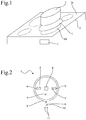
- Fig. 1 shows a system with an induction hob 2, a conventional cooking vessel 3 with an inductively heated, ferromagnetic ground and a measuring device 1 according to the invention, which is arranged in intended use in a sandwich configuration between a glass ceramic surface 2a of the hob 2 and the cooking vessel 3.
- a control device 7 for example in the form of a microprocessor, is used to control the function of the induction hob 2.
- the control device 7 can, for example, implement the appropriate control of the induction heating device, different heating programs, a timer control, a temperature control and so on.
- the disk-shaped or beer cover-shaped measuring device 1 When used as intended, the disk-shaped or beer cover-shaped measuring device 1 is arranged on the hob 10 of the induction hob 2 and the cooking vessel 3 placed on the measuring device 1. If the measuring device 1 fastening means (see also the following comments to Fig. 2 ), the measuring device 1 can be releasably secured to the bottom of the cooking vessel 3, so that the combination of measuring device 1 and cooking vessel 3 can be arranged on the cooking surface 10.
- Fig. 2 shows a more detailed representation of in Fig. 1 shown disc-shaped measuring device. 1
- the disc-shaped measuring device 1 may have a substantially circular inner region, for example with a suitable to common cooking vessel types and / or cooking vessel sizes Diameter of 150mm, 180mm, 210mm or 260mm. Of course, other shapes are possible.
- the measuring device 1 is merely to be shaped such that the cooking vessel 3 can be safely lowered onto it.
- the measuring device 1 has a projection 1 a, which adjoins the circular inner region and which is not covered by the cooking vessel 3 during normal use.
- all temperature-sensitive components of the measuring device are arranged, such as a microprocessor, analog and digital peripherals of the microprocessor, a wireless transmitter / receiver module, etc.
- the measuring device 1 may have a constant or maximum thickness between 2mm and 10mm, so that in the case of induction hobs no disturbing weakening of the generated alternating magnetic fields is caused.
- the measuring device 1 is made of materials that are not substantially heated by the induction heating. In general, these are not ferromagnetic materials, such as plastics, silicone, etc.
- the measuring device 1 has weight-measuring means 4, for example in the form of one or more load cells, which are designed to determine a weight, which causes of the cooking vessel 3 including any existing cooking vessel content and on the measuring device 1 and their Weight force measuring means 4 is exercised.
- weight-measuring means 4 for example in the form of one or more load cells, which are designed to determine a weight, which causes of the cooking vessel 3 including any existing cooking vessel content and on the measuring device 1 and their Weight force measuring means 4 is exercised.
- the measuring device 1 temperature measuring means, here in the form of three temperature sensors 5, which are adapted to a To determine the temperature of the cooking vessel bottom.
- the temperature sensors 5 are uniformly distributed on a circular arc, wherein the circular arc has a radius which corresponds to half of a radius of the circular cooking point 10.
- the measuring device 1 has data transmission means 6 which are designed to transmit the measured variables, ie the determined weight force and the specific temperature, wirelessly to the control device 7 of the hob 2, the cooking field 2 or its control device 7 corresponding data transmission means (not shown) having.
- the type of data transmission and the data transmission means are, for example, as in DE 10 2011 079 689 disclosed configured, wherein the DE 10 2011 079 689 is made by reference to the content of the description. It is understood that other conventional data transmission means and data transmission standards can also be used for data transmission, for example Bluetooth, WLAN, ISO 1444, etc.
- the measuring device 1 has display means in the form of a 7-segment display 8, which is designed to display the measured variables. It is understood that several 7-segment displays can be provided. Instead of a 7-segment display, other display means may also be provided, for example LCD displays, etc.
- the measured variables may be displayed in time division multiplex.
- the measuring device 1 may have operating means 11, for example in the form of capacitive buttons, which are designed to input operating parameters for the measuring device 1 itself and / or the hob 2. With an operating parameter setting, a visualization of the operating parameters can take place by means of the display means 8.
- the measuring device 1 has magnetic fastening means 9 which are designed to releasably fix the measuring device 1 to the bottom of the ferromagnetic cooking vessel 3.
- the control device 7 is designed to carry out the function control depending on the temperature determined by means of the measuring device 1 and / or the weight determined by the measuring device 1, so that, for example, predetermined temperature profiles can be run, an exact control of the bottom temperature of the pan becomes possible, etc.
- the unit or measuring device 1 in addition to a precise temperature measurement and a weighing function on induction hobs, regardless of the induction hob and regardless of the cooking vessel or pot.
- An integrated into the measuring device 1, optional display and control device 8/11 allows a comfortable reading of the measured variables and a comfortable input of parameters.
- the measured values since they are transmitted wirelessly to the induction hob 2, can also be visualized by means of a display of the induction hob 2. Accordingly, a parameterization can also take place by means of an operating device of the induction hob 2, wherein the parameters are then transmitted wirelessly to the measuring device 1.
- the temperature measurement makes it possible to heat to predefined temperatures or to cook according to temperature profiles.
- the weighing function can support cooking by allowing ingredients to be weighed directly on the ingredients, both during the cooking process and independently of a cooking process, without the need for a dedicated balance.
- volume of liquids for example in liters, and / or masses of solids, for example in grams, can be indicated based on the determined weight force and a possible zeroing in order to calculate the weight of the cooking vessel.
- weighing can be done, for example, an indication of added weight. Furthermore, a tare function can be realized. Further, a desired weight can be preset and displayed in sequence, how much weight is still to be added.
- the particular temperature and / or weight or weight may be optically outputted, for example by means of LED, 7-segment indicators, etc. It is also possible to have an acoustic output by means of loudspeaker or buzzer.
- keys may be provided on the measuring device 1. It is also conceivable speech recognition for voice input of the parameters.
Landscapes
- Engineering & Computer Science (AREA)
- Physics & Mathematics (AREA)
- Chemical & Material Sciences (AREA)
- Combustion & Propulsion (AREA)
- Mechanical Engineering (AREA)
- General Engineering & Computer Science (AREA)
- Electromagnetism (AREA)
- General Physics & Mathematics (AREA)
- Induction Heating Cooking Devices (AREA)
- Cookers (AREA)
Description
- Die Erfindung betrifft ein System mit einer Messeinrichtung, die zwischen einer Oberfläche eines Kochfelds und einem Kochgefäß anordenbar ist.
- Die
DE 10 2005 052 274 A1 , dieDE 10 2008 044 236 A1 und dieEP 1 074 823 A1 zeigen jeweils Kochfelder, in die Gewichtskraft-Messmittel integriert sind, die nicht frei auf dem Kochfeld verschiebbar und nicht vom Kochfeld entfernbar sind. - Die
US 6,300,603 B1 offenbart einen ansteuerbaren Elektromagneten, der ein unbeabsichtigtes Verschieben bzw. Abnehmen eines ferromagnetischen Kochgefäßes während eines Kochvorgangs verhindert. - Die
DE 20 2011 052 235 U1 zeigt eine Haushaltswaage. - Die
US 2010/0299074 A1 zeigt Wagen, die über eine drahtlose Schnittstelle Daten zu einer zentralen Steuereinheit übertragen können. - Der Erfindung liegt die Aufgabe zugrunde, ein System zur Verfügung zu stellen, mittels dem die Funktionsvielfalt eines Kochfelds erweitert werden kann.
- Die Erfindung löst diese Aufgabe durch ein System nach Anspruch 1.
- Das System weist ein Kochfeld auf, wobei das Kochfeld umfasst: eine Kochfeldoberfläche, beispielsweise eine Glaskeramikoberfläche, mindestens eine Kochstelle, mindestens eine Induktionsheizeinrichtung, die der Kochstelle zugeordnet ist, und eine Steuereinrichtung zur Funktionssteuerung des Kochfelds. Die Funktionssteuerung kann die geeignete Ansteuerung der Induktionsheizeinrichtung, unterschiedliche Heizprogramme, eine Timer-Steuerung, eine Temperaturregelung usw. implementieren. Das System weist weiter ein induktiv beheizbares Kochgefäß und eine Messeinrichtung auf.
- Die Messeinrichtung, mittels der mindestens eine Messgröße bestimmbar ist, ist zwischen der Kochfeldoberfläche und dem Kochgefäß, beispielsweise einem Kochtopf, anordenbar. Im bestimmungsgemäßen Gebrauch der Messeinrichtung wird diese zwischen Kochgefäß und Kochfeldoberfläche sandwichartig eingebracht bzw. angeordnet. Hierzu kann die Messeinrichtung auf die Oberfläche des Kochfelds aufgesetzt werden, wobei das Kochgefäß auf die Messeinrichtung aufgesetzt wird.
- Die Messeinrichtung ist bevorzugt vom Kochfeld getrennt vorgesehen, d.h. ist nicht integrierter bzw. integraler Bestandteil des Kochfelds.
- Die Messeinrichtung ist frei auf dem Kochfeld verschiebbar und vom Kochfeld entfernbar.
- Die Messeinrichtung weist Gewichtskraft-Messmittel auf, die dazu ausgebildet sind, eine Messgröße in Form einer Gewichtskraft zu bestimmen, die von dem Kochgefäß (und selbstverständlich Kochgut, das sich gegebenenfalls im Kochgefäß befindet) bewirkt wird, das auf der Messeinrichtung angeordnet ist. Die bestimmte Gewichtskraft kann beispielweise zum Wiegen von Zutaten/Kochgut ausgewertet werden, die/das in das Kochgefäß eingebracht werden/wird. Die Messeinrichtung kann eine Umwandlungseinrichtung aufweisen, die die bestimmte Gewichtskraft in eine entsprechende Maßangabe umwandelt. Es besteht selbstverständlich die Möglichkeit, dass in diesem Kontext ein Nullabgleich möglich/vorgesehen ist, so dass die Gewichtskraft des Kochgefäßes herausgerechnet wird.
- Die Messeinrichtung kann einen eigenen Betriebsenergiespeicher, beispielsweise in Form eines Akkumulators aufweisen. Alternativ oder zusätzlich kann die Messeinrichtung ihre Betriebsenergie auch aus einem magnetischen Wechselfeld erzeugen, welches im Heizbetrieb mittels des Induktionskochfelds erzeugt wird.
- Die Messeinrichtung ist dazu ausgebildet, beispielsweise aufgrund ihrer Materialeigenschaften, Dicke, Form und/oder Temperaturfestigkeit, während einer Erwärmung des Kochgefäßes mittels des Kochfelds zwischen der Oberfläche des Kochfelds und dem Kochgefäß angeordnet zu bleiben.
- Die Gewichtskraft-Messmittel können mindestens eine Wägezelle, mindestens einen piezoelektrischen Drucksensor und/oder mindestens einen kapazitiven Drucksensor aufweisen.
- Die Temperatur-Messmittel können dazu ausgebildet sein, eine weitere Messgröße in Form einer Temperatur eines Bodens des Kochgefäßes zu bestimmen, das auf der Messeinrichtung angeordnet ist. Die Temperatur-Messmittel können mehrere, beispielsweise zwei oder drei, Temperatursensoren umfassen, die beispielsweise gleichmäßig auf einem Kreisbogen verteilt sind, wobei der Kreisbogen einen Radius aufweisen kann, der beispielsweise der Hälfte eines Radius einer kreisförmigen Kochstelle entspricht.
- Die Messeinrichtung weist Datenübertragungsmittel auf, die dazu ausgebildet sind, die Messgrößen, d.h. die bestimmte Gewichtskraft und/oder die bestimmte Temperatur, drahtlos zu der Steuereinrichtung des Kochfelds zu übertragen.
- Die Messeinrichtung kann Anzeigemittel umfassen, die dazu ausgebildet sind, die Messgrößen anzuzeigen.
- Die Messeinrichtung kann Bedienmittel aufweisen, die dazu ausgebildet sind, Betriebsparameter für die Messeinrichtung selbst und/oder das Kochfeld einzugeben.
- Die Messeinrichtung weist Befestigungsmittel auf, die dazu ausgebildet sind, die Messeinrichtung lösbar an dem Boden des Kochgefäßes zu befestigen, insbesondere derart, dass bei einem Abheben des Kochgefäßes von der Oberfläche des Kochfelds auch die Messeinrichtung mit abgehoben wird.
- Die Befestigungsmittel können mindestens einen Magneten aufweisen.
- Die Messeinrichtung kann eine, beispielsweise gleichmäßige, Dicke zwischen 2mm und 10mm aufweisen, so dass für den Fall von Induktionskochfeldern keine störende Schwächung der erzeugten magnetischen Wechselfelder verursacht wird.
- Die Messeinrichtung besteht aus Materialien, die nicht durch die Induktionsheizeinrichtung erwärmbar sind. In der Regel sind dies nichtferromagnetische Materialien, beispielsweise Kunststoffe, Silikon, usw.
- Die Steuereinrichtung kann dazu ausgebildet sein, die Funktionssteuerung in Abhängigkeit von der mittels der Messeinrichtung bestimmten Temperatur und/oder der mittels der Messeinrichtung bestimmten Gewichtskraft durchzuführen, sodass beispielsweise vorgegebene Temperaturprofile gefahren werden können, eine exakte Regelung der Topfbodentemperatur möglich wird, ein mengenabhängiger Kochprozeß durchgeführt wird, usw.
- Die Erfindung wird nachfolgend unter Bezugnahme auf die Zeichnungen beschrieben. Hierbei zeigt schematisch:
- Fig. 1
- ein System mit einem Induktionskochfeld, einem induktiv beheizbaren Kochgefäß und einer erfindungsgemäßem Messeinrichtung, die in einer Sandwichkonfiguration zwischen einer Glaskeramikoberfläche des Kochfelds und dem Kochgefäß angeordnet ist, und
- Fig. 2
- eine detailliertere Darstellung der in
Fig. 1 gezeigten Messeinrichtung. -
Fig. 1 zeigt ein System mit einem Induktionskochfeld 2, einem herkömmlichen Kochgefäß 3 mit einem induktiv beheizbaren, ferromagnetischen Boden und einer erfindungsgemäßen Messeinrichtung 1, die beim bestimmungsgemäßen Gebrauch in einer Sandwichkonfiguration zwischen einer Glaskeramikoberfläche 2a des Kochfelds 2 und dem Kochgefäß 3 angeordnet ist. - Das Induktionskochfeld 2 weist herkömmlich mindestens eine kreisförmige Kochstelle 10 auf, der eine herkömmliche, nicht dargestellte Induktionsheizeinrichtung zugeordnet ist.
- Eine Steuereinrichtung 7, beispielsweise in Form eines Mikroprozessors, dient der Funktionssteuerung des Induktionskochfelds 2. Die Steuereinrichtung 7 kann beispielsweise die geeignete Ansteuerung der Induktionsheizeinrichtung, unterschiedliche Heizprogramme, eine Timer-Steuerung, eine Temperaturregelung usw. implementieren.
- Beim bestimmungsgemäßen Gebrauch wird die scheibenförmige oder bierdeckelförmige Messeinrichtung 1 auf der Kochstelle 10 des Induktionskochfelds 2 angeordnet und das Kochgefäß 3 auf die Messeinrichtung 1 gestellt. Falls die Messeinrichtung 1 Befestigungsmittel (siehe auch die nachfolgenden Ausführungen zu
Fig. 2 ) aufweist, kann die Messeinrichtung 1 lösbar am Boden des Kochgefäßes 3 befestigt werden, so dass die Kombination aus Messeinrichtung 1 und Kochgefäß 3 auf der Kochstelle 10 angeordnet werden kann. -
Fig. 2 zeigt eine detailliertere Darstellung der inFig. 1 gezeigten scheibenförmigen Messeinrichtung 1. - Die scheibenförmige Messeinrichtung 1 kann passend zu gängigen Kochgefäßtypen und/oder Kochgefäßgrößen einen im Wesentlichen kreisförmigen Innenbereich aufweisen, beispielsweise mit einem Durchmesser von 150mm, 180mm, 210mm oder 260mm. Selbstverständlich sind auch andere Formen möglich. Die Messeinrichtung 1 ist lediglich derart zu formen, dass das Kochgefäß 3 sicher auf ihr abstellbar ist.
- Die Messeinrichtung 1 weist einen Vorsprung 1 a auf, der an den kreisförmigen Innenbereich angrenzt und der beim bestimmungsgemäßen Gebrauch nicht von dem Kochgefäß 3 überdeckt ist.
- Im Vorsprung 1 a sind sämtliche temperaturempfindlichen Bauelemente der Messeinrichtung angeordnet, beispielsweise ein Mikroprozessor, analoge und digitale Peripherie des Mikroprozessors, ein drahtloser Sender/Empfänger-Baustein, usw.
- Die Messeinrichtung 1 kann eine gleichbleibende oder maximale Dicke zwischen 2mm und 10mm aufweisen, so dass für den Fall von Induktionskochfeldern keine störende Schwächung der erzeugten magnetischen Wechselfelder verursacht wird.
- Die Messeinrichtung 1 besteht aus Materialien, die im Wesentlichen nicht durch die Induktionsheizeinrichtung erwärmbar sind. In der Regel sind dies nicht ferromagnetische Materialien, beispielsweise Kunststoffe, Silikon, usw.
- Die Messeinrichtung 1 weist Gewichtskraft-Messmittel 4, beispielsweise in Form von einer oder mehreren Wägezellen, auf, die dazu ausgebildet sind, eine Gewichtskraft zu bestimmen, die von dem Kochgefäß 3 inklusive eventuell vorhandenem Kochgefäß-Inhalt bewirkt und auf die Messeinrichtung 1 bzw. deren Gewichtskraft-Messmittel 4 ausgeübt wird.
- Weiter weist die Messeinrichtung 1 Temperatur-Messmittel, hier in Form von drei Temperatursensoren 5 auf, die dazu ausgebildet sind, eine Temperatur des Kochgefäßbodens zu bestimmen. Die Temperatursensoren 5 sind gleichmäßig auf einem Kreisbogen verteilt, wobei der Kreisbogen einen Radius aufweist, der der Hälfte eines Radius der kreisförmigen Kochstelle 10 entspricht.
- Die Messeinrichtung 1 weist Datenübertragungsmittel 6 auf, die dazu ausgebildet sind, die Messgrößen, d.h. die bestimmte Gewichtskraft und die bestimmte Temperatur, drahtlos zu der Steuereinrichtung 7 des Kochfelds 2 zu übertragen, wobei das Kochfeld 2 bzw. dessen Steuereinrichtung 7 korrespondierende, nicht gezeigte Datenübertragungsmittel aufweist. Die Art der Datenübertragung sowie die Datenübertragungsmittel sind beispielsweise wie in der
DE 10 2011 079 689 offenbart ausgestaltet, wobei dieDE 10 2011 079 689 durch Bezugnahme zum Inhalt der Beschreibung gemacht wird. Es versteht sich, dass auch weitere, herkömmliche Datenübertragungsmittel und Datenübertragungsstandards zur Datenübertragung verwendet werden können, beispielsweise Bluetooth, WLAN, ISO 1444, usw. - Die Messeinrichtung 1 weist Anzeigemittel in Form einer 7-Segment-Anzeige 8 auf, die dazu ausgebildet ist, die Messgrößen anzuzeigen. Es versteht sich, dass auch mehrere 7-Segment-Anzeigen vorgesehen sein können. Anstelle einer 7-Segment-Anzeige können auch andere Anzeigemittel vorgesehen sein, beispielsweise LCD-Anzeigen, usw. Die Messgrößen können im Zeitmultiplex angezeigt werden.
- Die Messeinrichtung 1 kann Bedienmittel 11, beispielsweise in Form von kapazitiven Tasten, aufweisen, die dazu ausgebildet sind, Betriebsparameter für die Messeinrichtung 1 selbst und/oder das Kochfeld 2 einzugeben. Bei einer Betriebsparametereinstellung kann eine Visualisierung der Betriebsparameter mittels der Anzeigemittel 8 erfolgen.
- Die Messeinrichtung 1 weist magnetische Befestigungsmittel 9 auf, die dazu ausgebildet sind, die Messeinrichtung 1 lösbar an dem Boden des ferromagnetischen Kochgefäßes 3 zu befestigen.
- Die Steuereinrichtung 7 ist dazu ausgebildet, die Funktionssteuerung in Abhängigkeit von der mittels der Messeinrichtung 1 bestimmten Temperatur und/oder der mittels der Messeinrichtung 1 bestimmten Gewichtskraft durchzuführen, sodass beispielsweise vorgegebene Temperaturprofile gefahren werden können, eine exakte Regelung der Topfbodentemperatur möglich wird, usw.
- Erfindungsgemäß ermöglicht die Einheit bzw. Messeinrichtung 1 neben einer exakten Temperaturmessung auch eine Wiegefunktion auf Induktionskochfeldern, unabhängig vom Induktionskochfeld und unabhängig vom Kochgefäß bzw. Topf.
- Eine in die Messeinrichtung 1 integrierte, optionale Anzeige- und Bedieneinrichtung 8/11 ermöglicht ein komfortables Ablesen der Messgrößen und eine komfortable Eingabe von Parametern. Alternativ oder zusätzlich können die Messwerte, da sie drahtlos zum Induktionskochfeld 2 übertragen werden, auch mittels einer Anzeige des Induktionskochfelds 2 visualisiert werden. Entsprechend kann eine Parametrierung auch mittels einer Bedieneinrichtung des Induktionskochfelds 2 erfolgen, wobei die Parameter dann drahtlos zur Messeinrichtung 1 übertragen werden.
- Die Temperaturmessung ermöglicht es auf vordefinierte Temperaturen zu erwärmen bzw. nach Temperaturprofilen zu kochen.
- Die Wiegefunktion kann das Kochen dadurch unterstützen, dass Zutaten direkt beim Zugegeben abgewogen werden können, sowohl während des Kochprozesses als auch unabhängig von einem Kochprozess, ohne dass hierzu eine dedizierte Waage vorzusehen wäre.
- Mittels der Messeinrichtung 1 können basierend auf der bestimmten Gewichtskraft und einer eventuell vorgenommenen Nullung, um die Gewichtskraft des Kochgefäßes herauszurechnen, Volumen von Flüssigkeiten beispielsweise in Liter angeben und/oder Massen von Feststoffen beispielsweise in Gramm angegeben werden.
- Beim Wiegen kann beispielweise ein Anzeigen von zugegebenem Gewicht erfolgen. Weiter kann eine Tara-Funktion realisiert sein. Weiter kann ein gewünschtes Gewicht voreingestellt werden und in Folge angezeigt werden, wie viel Gewicht noch zuzugeben ist.
- Die bestimmte Temperatur und/oder die bestimmte Gewichtskraft bzw. das entsprechende Gewicht kann/können optisch ausgegeben werden, beispielsweise mittels LED, 7-Sgement-Anzeigen, usw. Es ist auch eine akustische Ausgabe mittels Lautsprecher oder Summer möglich.
- Zur Eingabe von Parametern können Tasten, Slider, ein Touch-Screen usw. an der Messeinrichtung 1 vorgesehen sein. Denkbar ist auch eine Spracherkennung zur Spracheingabe der Parameter.
Claims (9)
- System, aufweisend:- ein Kochfeld (2) mit- einer Kochfeldoberfläche (2a),- mindestens einer Kochstelle (10),- mindestens einer Induktionsheizeinrichtung, die der Kochstelle (10) zugeordnet ist, und- einer Steuereinrichtung (7) zur Funktionssteuerung des Kochfelds (2),- ein induktiv beheizbares Kochgefäß (3) und- eine Messeinrichtung (1), die zwischen der Kochfeldoberfläche (2a) des Kochfelds (2) und dem Kochgefäß (3) anordenbar ist, die frei auf dem Kochfeld (2) verschiebbar ist und die vom Kochfeld (2) entfernbar ist, aufweisend:- Gewichtskraft-Messmittel (4), die dazu ausgebildet sind, eine Gewichtskraft zu bestimmen, die von dem Kochgefäß (3) bewirkt wird, das auf der Messeinrichtung (1) angeordnet ist,- Datenübertragungsmittel (6), die dazu ausgebildet sind, die bestimmte Gewichtskraft drahtlos zu der Steuereinrichtung (7) des Kochfelds (2) zu übertragen, und- Befestigungsmittel (9), die dazu ausgebildet sind, die Messeinrichtung (1) lösbar an dem Boden des Kochgefäßes (3) zu befestigen.
- System nach Anspruch 1, dadurch gekennzeichnet dass- die Messeinrichtung (1) dazu ausgebildet ist, während einer Erwärmung des Kochgefäßes (3) mittels des Kochfelds (2) zwischen der Kochfeldoberfläche (2a) und dem Kochgefäß (3) angeordnet zu bleiben.
- System nach Anspruch 1 oder 2, dadurch gekennzeichnet dass- die Gewichtskraft-Messmittel (4) mindestens eine Wägezelle, mindestens einen piezoelektrischen Drucksensor und/oder mindestens einen kapazitiven Drucksensor aufweisen.
- System nach einem der vorhergehenden Ansprüche, gekennzeichnet durch- Temperatur-Messmittel (5), die dazu ausgebildet sind, eine Temperatur eines Bodens des Kochgefäßes (3) zu bestimmen, das auf der Messeinrichtung (1) angeordnet ist.
- System nach Anspruch 4, dadurch gekennzeichnet, dass- die Datenübertragungsmittel (6) dazu ausgebildet sind, die bestimmte Temperatur drahtlos zu der Steuereinrichtung (7) des Kochfelds (2) zu übertragen.
- System nach einem der vorhergehenden Ansprüche, gekennzeichnet durch- Anzeigemittel (8), die dazu ausgebildet sind, die bestimmte Gewichtskraft anzuzeigen, und/oder- Bedienmittel, die dazu ausgebildet sind, Betriebsparameter für die Messeinrichtung und/oder das Kochfeld (2) einzugeben.
- System nach einem der vorhergehenden Ansprüche, dadurch gekennzeichnet, dass- die Befestigungsmittel mindestens einen Magneten (9) aufweisen.
- System nach einem der vorhergehenden Ansprüche, dadurch gekennzeichnet, dass- die Messeinrichtung (1) eine Dicke zwischen 2mm und 10mm aufweist.
- System nach einem der vorhergehenden Ansprüche, dadurch gekennzeichnet, dass- die Steuereinrichtung (7) dazu ausgebildet ist, die Funktionssteuerung in Abhängigkeit von der mittels der Messeinrichtung (1) bestimmten Gewichtskraft durchzuführen.
Priority Applications (1)
| Application Number | Priority Date | Filing Date | Title |
|---|---|---|---|
| PL13178870T PL2693127T3 (pl) | 2012-08-03 | 2013-08-01 | System posiadający urządzenie pomiarowe |
Applications Claiming Priority (1)
| Application Number | Priority Date | Filing Date | Title |
|---|---|---|---|
| DE102012213831.5A DE102012213831A1 (de) | 2012-08-03 | 2012-08-03 | Messeinrichtung und System |
Publications (2)
| Publication Number | Publication Date |
|---|---|
| EP2693127A1 EP2693127A1 (de) | 2014-02-05 |
| EP2693127B1 true EP2693127B1 (de) | 2017-05-17 |
Family
ID=48915882
Family Applications (1)
| Application Number | Title | Priority Date | Filing Date |
|---|---|---|---|
| EP13178870.5A Active EP2693127B1 (de) | 2012-08-03 | 2013-08-01 | System aufweisend eine Messeinrichtung |
Country Status (4)
| Country | Link |
|---|---|
| EP (1) | EP2693127B1 (de) |
| DE (1) | DE102012213831A1 (de) |
| ES (1) | ES2632838T3 (de) |
| PL (1) | PL2693127T3 (de) |
Cited By (1)
| Publication number | Priority date | Publication date | Assignee | Title |
|---|---|---|---|---|
| WO2025238196A1 (en) * | 2024-05-16 | 2025-11-20 | Handigood Aps | Safety device for an induction stove top |
Families Citing this family (17)
| Publication number | Priority date | Publication date | Assignee | Title |
|---|---|---|---|---|
| KR101589701B1 (ko) * | 2015-08-13 | 2016-01-28 | (주)피스월드 | 스마트 언더렌지용 조리용기 받침장치 |
| EP3355663A4 (de) * | 2015-09-25 | 2018-09-19 | Panasonic Intellectual Property Management Co., Ltd. | Kochvorrichtung |
| ES2618810B1 (es) | 2015-12-17 | 2018-04-06 | Bsh Electrodomésticos España, S.A. | Dispositivo subyacente previsto para disponerse entre una batería de cocción y un campo de cocción |
| ES2618798B1 (es) | 2015-12-17 | 2018-04-06 | Bsh Electrodomésticos España, S.A. | Sistema de aparato doméstico con campo de cocción y unidad funcional |
| DE102016114838B4 (de) * | 2016-08-10 | 2019-12-05 | Miele & Cie. Kg | Induktives Kochsystem |
| GB2552972B (en) * | 2016-08-16 | 2020-01-15 | Richards Morphy N I Ltd | Induction cooking method and apparatus |
| DE202016105148U1 (de) | 2016-09-15 | 2016-09-29 | Priscilla Munke | Küchengefäß mit integrierter Wiegevorrichtung |
| ES2685024B1 (es) * | 2017-03-30 | 2019-07-18 | Bsh Electrodomesticos Espana Sa | Sistema de coccion y procedimiento para posicionar un elemento de bateria de coccion |
| ES2684179B1 (es) * | 2017-03-30 | 2019-07-29 | Bsh Electrodomesticos Espana Sa | Dispositivo de campo de coccion y procedimiento para la puesta en funcionamiento de un dispositivo de campo de coccion |
| ES2696224A1 (es) * | 2017-07-11 | 2019-01-14 | Bsh Electrodomesticos Espana Sa | Dispositivo de cocción y procedimiento para el funcionamiento de un dispositivo de cocción |
| CN109724704B (zh) * | 2017-10-30 | 2020-03-06 | 佛山市顺德区美的电热电器制造有限公司 | 电磁炉测温方法、测温装置及可读储存介质 |
| DE102017131155A1 (de) | 2017-12-22 | 2019-06-27 | Miele & Cie. Kg | Küchengefäß mit einem Wiegesensor, Garsystem mit einem Gargerät und einem Küchengefäß und Verfahren zum Betrieb eines Küchengefäßes |
| ES2767368A1 (es) * | 2018-12-17 | 2020-06-17 | Bsh Electrodomesticos Espana Sa | Sistema de preparación de alimentos |
| DE102019112418A1 (de) * | 2019-05-13 | 2020-11-19 | Miele & Cie. Kg | Standdampfgarer |
| WO2021069221A1 (de) * | 2019-10-08 | 2021-04-15 | BSH Hausgeräte GmbH | Induktionsenergieübertragungssystem |
| WO2024246627A1 (en) * | 2023-05-26 | 2024-12-05 | Bs Service Group S.R.L. | System for energy saving and improved cooking in induction cooktops |
| LU103422B1 (de) * | 2024-10-21 | 2026-04-21 | Miele & Cie | Untersetzervorrichtung für ein Gargefäß, Induktionsvorrichtung und Verfahren zum Erhitzen eines Gargefäßes |
Citations (1)
| Publication number | Priority date | Publication date | Assignee | Title |
|---|---|---|---|---|
| US20100299074A1 (en) * | 2007-11-01 | 2010-11-25 | David Chang | Remote data collecting systems and methods |
Family Cites Families (10)
| Publication number | Priority date | Publication date | Assignee | Title |
|---|---|---|---|---|
| DE19931169A1 (de) * | 1999-07-06 | 2001-01-11 | Bsh Bosch Siemens Hausgeraete | Anordnung mit Gargerät und Kochfeld mit integrierter Wägefunktion |
| EP1074823A1 (de) * | 1999-08-05 | 2001-02-07 | Walter Schroeder | Kochfeld mit Gewichtsmesseinheit |
| US6300603B1 (en) * | 2000-06-08 | 2001-10-09 | Stephen Patrick Edwards | Stovetop burner with safety feature |
| DE10064621A1 (de) * | 2000-12-21 | 2002-06-27 | Ego Elektro Geraetebau Gmbh | Verfahren und Vorrichtung zur Erfassung der Tenperatur eines Kochgefäßes |
| DE10344337A1 (de) * | 2003-09-24 | 2005-05-04 | Bsh Bosch Siemens Hausgeraete | Vorrichtung mit einer Kochfeldplatte und einer Wägeeinrichtung |
| DE10353299B4 (de) * | 2003-11-11 | 2008-03-20 | E.G.O. Elektro-Gerätebau GmbH | Verfahren zur Regelung einer Heizeinrichtung zur Nahrungsmittelzubereitung und geeignete Vorrichtung |
| DE102005052274B4 (de) * | 2005-10-27 | 2010-04-08 | E.G.O. Elektro-Gerätebau GmbH | Kochgerät |
| DE102008044236A1 (de) * | 2008-12-01 | 2010-06-02 | BSH Bosch und Siemens Hausgeräte GmbH | Kochfeld mit einer Kochfeldplatte und einer Wägeeinrichtung |
| DE102011079689B4 (de) | 2011-07-22 | 2014-07-03 | E.G.O. Elektro-Gerätebau GmbH | Temperaturmessung im Kochgefäß |
| DE202011052235U1 (de) * | 2011-12-08 | 2012-01-16 | Beurer Gmbh | Haushaltswaage |
-
2012
- 2012-08-03 DE DE102012213831.5A patent/DE102012213831A1/de not_active Withdrawn
-
2013
- 2013-08-01 PL PL13178870T patent/PL2693127T3/pl unknown
- 2013-08-01 EP EP13178870.5A patent/EP2693127B1/de active Active
- 2013-08-01 ES ES13178870.5T patent/ES2632838T3/es active Active
Patent Citations (1)
| Publication number | Priority date | Publication date | Assignee | Title |
|---|---|---|---|---|
| US20100299074A1 (en) * | 2007-11-01 | 2010-11-25 | David Chang | Remote data collecting systems and methods |
Cited By (1)
| Publication number | Priority date | Publication date | Assignee | Title |
|---|---|---|---|---|
| WO2025238196A1 (en) * | 2024-05-16 | 2025-11-20 | Handigood Aps | Safety device for an induction stove top |
Also Published As
| Publication number | Publication date |
|---|---|
| PL2693127T3 (pl) | 2017-10-31 |
| DE102012213831A1 (de) | 2014-05-22 |
| ES2632838T3 (es) | 2017-09-15 |
| EP2693127A1 (de) | 2014-02-05 |
Similar Documents
| Publication | Publication Date | Title |
|---|---|---|
| EP2693127A1 (de) | Messeinrichtung und System | |
| EP2661944B1 (de) | Induktionskochgerät zum temperaturgesteuerten kochen | |
| EP2775212B1 (de) | Verfahren zum Betrieb einer Kocheinrichtung, Steuerungseinheit und Kocheinrichtung | |
| EP3376919B1 (de) | Vorrichtung zum kochen von lebensmitteln | |
| EP0637898B1 (de) | Arbeitsplattenkochfeld | |
| EP1793653A3 (de) | Vorrichtung und Verfahren zur erfassen von Lasten eines Elektroherdes | |
| EP2590473B1 (de) | Gargerätevorrichtung | |
| WO2007124891A1 (de) | Vorrichtung und verfahren zur temperaturmessung an einer induktionsheizvorrichtung | |
| DE102013218785B4 (de) | Verfahren und Vorrichtung zum Garen von Lebensmitteln | |
| DE102009045521B4 (de) | Wasserkocheinrichtung | |
| DE102015103380A1 (de) | Verfahren und System mit einer Steuerung für die Zubereitung von Speisen | |
| DE102005052274B4 (de) | Kochgerät | |
| AU2015275269A1 (en) | Toaster with temperature control | |
| CN204133105U (zh) | 配有食物重量控制和卡路里计算功能的食品热处理装置 | |
| EP2827680A1 (de) | Kochfeldvorrichtung | |
| EP2405203A1 (de) | Kochvorrichtung | |
| EP3383134A1 (de) | Kochsystem und verfahren zu einer positionierung eines kochgeschirrelements | |
| EP4272614A1 (de) | Küchengerät mit waage für benutzerschnittstelle | |
| EP3632275A1 (de) | Haushaltsgerätesystem | |
| EP3001163A1 (de) | Gargerätevorrichtung | |
| EP2397771A1 (de) | Vorrichtung und Verfahren zur Zubereitung von Lebensmitteln in einem Garofen | |
| EP2765826B1 (de) | Kochassistenzsystem mit mobiler Messeinheit | |
| DE102020203762A1 (de) | Garsystem | |
| EP3636121B1 (de) | Küchengerät mit einheitenumrechnung | |
| CN202128359U (zh) | 掌握火候的锅柄 |
Legal Events
| Date | Code | Title | Description |
|---|---|---|---|
| AK | Designated contracting states |
Kind code of ref document: A1 Designated state(s): AL AT BE BG CH CY CZ DE DK EE ES FI FR GB GR HR HU IE IS IT LI LT LU LV MC MK MT NL NO PL PT RO RS SE SI SK SM TR |
|
| AX | Request for extension of the european patent |
Extension state: BA ME |
|
| PUAI | Public reference made under article 153(3) epc to a published international application that has entered the european phase |
Free format text: ORIGINAL CODE: 0009012 |
|
| 17P | Request for examination filed |
Effective date: 20140731 |
|
| RBV | Designated contracting states (corrected) |
Designated state(s): AL AT BE BG CH CY CZ DE DK EE ES FI FR GB GR HR HU IE IS IT LI LT LU LV MC MK MT NL NO PL PT RO RS SE SI SK SM TR |
|
| 17Q | First examination report despatched |
Effective date: 20151222 |
|
| REG | Reference to a national code |
Ref country code: DE Ref legal event code: R079 Ref document number: 502013007265 Country of ref document: DE Free format text: PREVIOUS MAIN CLASS: F24C0007080000 Ipc: G01G0019560000 |
|
| GRAP | Despatch of communication of intention to grant a patent |
Free format text: ORIGINAL CODE: EPIDOSNIGR1 |
|
| RIC1 | Information provided on ipc code assigned before grant |
Ipc: F24C 7/08 20060101ALI20161115BHEP Ipc: H05B 6/06 20060101ALI20161115BHEP Ipc: H05B 6/12 20060101ALI20161115BHEP Ipc: G01G 19/56 20060101AFI20161115BHEP |
|
| INTG | Intention to grant announced |
Effective date: 20161208 |
|
| GRAS | Grant fee paid |
Free format text: ORIGINAL CODE: EPIDOSNIGR3 |
|
| GRAA | (expected) grant |
Free format text: ORIGINAL CODE: 0009210 |
|
| AK | Designated contracting states |
Kind code of ref document: B1 Designated state(s): AL AT BE BG CH CY CZ DE DK EE ES FI FR GB GR HR HU IE IS IT LI LT LU LV MC MK MT NL NO PL PT RO RS SE SI SK SM TR |
|
| REG | Reference to a national code |
Ref country code: GB Ref legal event code: FG4D Free format text: NOT ENGLISH |
|
| REG | Reference to a national code |
Ref country code: CH Ref legal event code: EP |
|
| REG | Reference to a national code |
Ref country code: IE Ref legal event code: FG4D Free format text: LANGUAGE OF EP DOCUMENT: GERMAN |
|
| REG | Reference to a national code |
Ref country code: AT Ref legal event code: REF Ref document number: 894886 Country of ref document: AT Kind code of ref document: T Effective date: 20170615 |
|
| REG | Reference to a national code |
Ref country code: DE Ref legal event code: R096 Ref document number: 502013007265 Country of ref document: DE |
|
| REG | Reference to a national code |
Ref country code: FR Ref legal event code: PLFP Year of fee payment: 5 |
|
| REG | Reference to a national code |
Ref country code: ES Ref legal event code: FG2A Ref document number: 2632838 Country of ref document: ES Kind code of ref document: T3 Effective date: 20170915 |
|
| REG | Reference to a national code |
Ref country code: NL Ref legal event code: MP Effective date: 20170517 |
|
| REG | Reference to a national code |
Ref country code: LT Ref legal event code: MG4D |
|
| PG25 | Lapsed in a contracting state [announced via postgrant information from national office to epo] |
Ref country code: FI Free format text: LAPSE BECAUSE OF FAILURE TO SUBMIT A TRANSLATION OF THE DESCRIPTION OR TO PAY THE FEE WITHIN THE PRESCRIBED TIME-LIMIT Effective date: 20170517 Ref country code: NO Free format text: LAPSE BECAUSE OF FAILURE TO SUBMIT A TRANSLATION OF THE DESCRIPTION OR TO PAY THE FEE WITHIN THE PRESCRIBED TIME-LIMIT Effective date: 20170817 Ref country code: LT Free format text: LAPSE BECAUSE OF FAILURE TO SUBMIT A TRANSLATION OF THE DESCRIPTION OR TO PAY THE FEE WITHIN THE PRESCRIBED TIME-LIMIT Effective date: 20170517 Ref country code: HR Free format text: LAPSE BECAUSE OF FAILURE TO SUBMIT A TRANSLATION OF THE DESCRIPTION OR TO PAY THE FEE WITHIN THE PRESCRIBED TIME-LIMIT Effective date: 20170517 Ref country code: GR Free format text: LAPSE BECAUSE OF FAILURE TO SUBMIT A TRANSLATION OF THE DESCRIPTION OR TO PAY THE FEE WITHIN THE PRESCRIBED TIME-LIMIT Effective date: 20170818 |
|
| PG25 | Lapsed in a contracting state [announced via postgrant information from national office to epo] |
Ref country code: SE Free format text: LAPSE BECAUSE OF FAILURE TO SUBMIT A TRANSLATION OF THE DESCRIPTION OR TO PAY THE FEE WITHIN THE PRESCRIBED TIME-LIMIT Effective date: 20170517 Ref country code: LV Free format text: LAPSE BECAUSE OF FAILURE TO SUBMIT A TRANSLATION OF THE DESCRIPTION OR TO PAY THE FEE WITHIN THE PRESCRIBED TIME-LIMIT Effective date: 20170517 Ref country code: RS Free format text: LAPSE BECAUSE OF FAILURE TO SUBMIT A TRANSLATION OF THE DESCRIPTION OR TO PAY THE FEE WITHIN THE PRESCRIBED TIME-LIMIT Effective date: 20170517 Ref country code: IS Free format text: LAPSE BECAUSE OF FAILURE TO SUBMIT A TRANSLATION OF THE DESCRIPTION OR TO PAY THE FEE WITHIN THE PRESCRIBED TIME-LIMIT Effective date: 20170917 Ref country code: NL Free format text: LAPSE BECAUSE OF FAILURE TO SUBMIT A TRANSLATION OF THE DESCRIPTION OR TO PAY THE FEE WITHIN THE PRESCRIBED TIME-LIMIT Effective date: 20170517 Ref country code: BG Free format text: LAPSE BECAUSE OF FAILURE TO SUBMIT A TRANSLATION OF THE DESCRIPTION OR TO PAY THE FEE WITHIN THE PRESCRIBED TIME-LIMIT Effective date: 20170817 |
|
| PG25 | Lapsed in a contracting state [announced via postgrant information from national office to epo] |
Ref country code: SK Free format text: LAPSE BECAUSE OF FAILURE TO SUBMIT A TRANSLATION OF THE DESCRIPTION OR TO PAY THE FEE WITHIN THE PRESCRIBED TIME-LIMIT Effective date: 20170517 Ref country code: EE Free format text: LAPSE BECAUSE OF FAILURE TO SUBMIT A TRANSLATION OF THE DESCRIPTION OR TO PAY THE FEE WITHIN THE PRESCRIBED TIME-LIMIT Effective date: 20170517 Ref country code: RO Free format text: LAPSE BECAUSE OF FAILURE TO SUBMIT A TRANSLATION OF THE DESCRIPTION OR TO PAY THE FEE WITHIN THE PRESCRIBED TIME-LIMIT Effective date: 20170517 Ref country code: CZ Free format text: LAPSE BECAUSE OF FAILURE TO SUBMIT A TRANSLATION OF THE DESCRIPTION OR TO PAY THE FEE WITHIN THE PRESCRIBED TIME-LIMIT Effective date: 20170517 Ref country code: DK Free format text: LAPSE BECAUSE OF FAILURE TO SUBMIT A TRANSLATION OF THE DESCRIPTION OR TO PAY THE FEE WITHIN THE PRESCRIBED TIME-LIMIT Effective date: 20170517 |
|
| REG | Reference to a national code |
Ref country code: DE Ref legal event code: R097 Ref document number: 502013007265 Country of ref document: DE |
|
| PG25 | Lapsed in a contracting state [announced via postgrant information from national office to epo] |
Ref country code: SM Free format text: LAPSE BECAUSE OF FAILURE TO SUBMIT A TRANSLATION OF THE DESCRIPTION OR TO PAY THE FEE WITHIN THE PRESCRIBED TIME-LIMIT Effective date: 20170517 |
|
| PLBE | No opposition filed within time limit |
Free format text: ORIGINAL CODE: 0009261 |
|
| STAA | Information on the status of an ep patent application or granted ep patent |
Free format text: STATUS: NO OPPOSITION FILED WITHIN TIME LIMIT |
|
| REG | Reference to a national code |
Ref country code: CH Ref legal event code: PL |
|
| PG25 | Lapsed in a contracting state [announced via postgrant information from national office to epo] |
Ref country code: MC Free format text: LAPSE BECAUSE OF FAILURE TO SUBMIT A TRANSLATION OF THE DESCRIPTION OR TO PAY THE FEE WITHIN THE PRESCRIBED TIME-LIMIT Effective date: 20170517 |
|
| 26N | No opposition filed |
Effective date: 20180220 |
|
| PG25 | Lapsed in a contracting state [announced via postgrant information from national office to epo] |
Ref country code: LI Free format text: LAPSE BECAUSE OF NON-PAYMENT OF DUE FEES Effective date: 20170831 Ref country code: CH Free format text: LAPSE BECAUSE OF NON-PAYMENT OF DUE FEES Effective date: 20170831 |
|
| REG | Reference to a national code |
Ref country code: IE Ref legal event code: MM4A |
|
| PG25 | Lapsed in a contracting state [announced via postgrant information from national office to epo] |
Ref country code: SI Free format text: LAPSE BECAUSE OF FAILURE TO SUBMIT A TRANSLATION OF THE DESCRIPTION OR TO PAY THE FEE WITHIN THE PRESCRIBED TIME-LIMIT Effective date: 20170517 |
|
| REG | Reference to a national code |
Ref country code: BE Ref legal event code: MM Effective date: 20170831 |
|
| PG25 | Lapsed in a contracting state [announced via postgrant information from national office to epo] |
Ref country code: LU Free format text: LAPSE BECAUSE OF NON-PAYMENT OF DUE FEES Effective date: 20170801 |
|
| PG25 | Lapsed in a contracting state [announced via postgrant information from national office to epo] |
Ref country code: IE Free format text: LAPSE BECAUSE OF NON-PAYMENT OF DUE FEES Effective date: 20170801 |
|
| REG | Reference to a national code |
Ref country code: FR Ref legal event code: PLFP Year of fee payment: 6 |
|
| PG25 | Lapsed in a contracting state [announced via postgrant information from national office to epo] |
Ref country code: BE Free format text: LAPSE BECAUSE OF NON-PAYMENT OF DUE FEES Effective date: 20170831 |
|
| PG25 | Lapsed in a contracting state [announced via postgrant information from national office to epo] |
Ref country code: MT Free format text: LAPSE BECAUSE OF FAILURE TO SUBMIT A TRANSLATION OF THE DESCRIPTION OR TO PAY THE FEE WITHIN THE PRESCRIBED TIME-LIMIT Effective date: 20170517 |
|
| PG25 | Lapsed in a contracting state [announced via postgrant information from national office to epo] |
Ref country code: HU Free format text: LAPSE BECAUSE OF FAILURE TO SUBMIT A TRANSLATION OF THE DESCRIPTION OR TO PAY THE FEE WITHIN THE PRESCRIBED TIME-LIMIT; INVALID AB INITIO Effective date: 20130801 |
|
| REG | Reference to a national code |
Ref country code: AT Ref legal event code: MM01 Ref document number: 894886 Country of ref document: AT Kind code of ref document: T Effective date: 20180801 |
|
| PG25 | Lapsed in a contracting state [announced via postgrant information from national office to epo] |
Ref country code: CY Free format text: LAPSE BECAUSE OF NON-PAYMENT OF DUE FEES Effective date: 20170517 |
|
| PG25 | Lapsed in a contracting state [announced via postgrant information from national office to epo] |
Ref country code: MK Free format text: LAPSE BECAUSE OF FAILURE TO SUBMIT A TRANSLATION OF THE DESCRIPTION OR TO PAY THE FEE WITHIN THE PRESCRIBED TIME-LIMIT Effective date: 20170517 |
|
| PG25 | Lapsed in a contracting state [announced via postgrant information from national office to epo] |
Ref country code: AT Free format text: LAPSE BECAUSE OF NON-PAYMENT OF DUE FEES Effective date: 20180801 |
|
| PG25 | Lapsed in a contracting state [announced via postgrant information from national office to epo] |
Ref country code: TR Free format text: LAPSE BECAUSE OF FAILURE TO SUBMIT A TRANSLATION OF THE DESCRIPTION OR TO PAY THE FEE WITHIN THE PRESCRIBED TIME-LIMIT Effective date: 20170517 |
|
| PG25 | Lapsed in a contracting state [announced via postgrant information from national office to epo] |
Ref country code: PT Free format text: LAPSE BECAUSE OF FAILURE TO SUBMIT A TRANSLATION OF THE DESCRIPTION OR TO PAY THE FEE WITHIN THE PRESCRIBED TIME-LIMIT Effective date: 20170517 |
|
| PG25 | Lapsed in a contracting state [announced via postgrant information from national office to epo] |
Ref country code: AL Free format text: LAPSE BECAUSE OF FAILURE TO SUBMIT A TRANSLATION OF THE DESCRIPTION OR TO PAY THE FEE WITHIN THE PRESCRIBED TIME-LIMIT Effective date: 20170517 |
|
| PGFP | Annual fee paid to national office [announced via postgrant information from national office to epo] |
Ref country code: IT Payment date: 20220831 Year of fee payment: 10 Ref country code: GB Payment date: 20220824 Year of fee payment: 10 Ref country code: ES Payment date: 20220919 Year of fee payment: 10 |
|
| PGFP | Annual fee paid to national office [announced via postgrant information from national office to epo] |
Ref country code: PL Payment date: 20220725 Year of fee payment: 10 Ref country code: FR Payment date: 20220822 Year of fee payment: 10 |
|
| GBPC | Gb: european patent ceased through non-payment of renewal fee |
Effective date: 20230801 |
|
| PG25 | Lapsed in a contracting state [announced via postgrant information from national office to epo] |
Ref country code: GB Free format text: LAPSE BECAUSE OF NON-PAYMENT OF DUE FEES Effective date: 20230801 |
|
| PG25 | Lapsed in a contracting state [announced via postgrant information from national office to epo] |
Ref country code: IT Free format text: LAPSE BECAUSE OF NON-PAYMENT OF DUE FEES Effective date: 20230801 Ref country code: GB Free format text: LAPSE BECAUSE OF NON-PAYMENT OF DUE FEES Effective date: 20230801 Ref country code: FR Free format text: LAPSE BECAUSE OF NON-PAYMENT OF DUE FEES Effective date: 20230831 |
|
| REG | Reference to a national code |
Ref country code: ES Ref legal event code: FD2A Effective date: 20240927 |
|
| PG25 | Lapsed in a contracting state [announced via postgrant information from national office to epo] |
Ref country code: ES Free format text: LAPSE BECAUSE OF NON-PAYMENT OF DUE FEES Effective date: 20230802 |
|
| PG25 | Lapsed in a contracting state [announced via postgrant information from national office to epo] |
Ref country code: PL Free format text: LAPSE BECAUSE OF NON-PAYMENT OF DUE FEES Effective date: 20230801 |
|
| PG25 | Lapsed in a contracting state [announced via postgrant information from national office to epo] |
Ref country code: PL Free format text: LAPSE BECAUSE OF NON-PAYMENT OF DUE FEES Effective date: 20230801 Ref country code: ES Free format text: LAPSE BECAUSE OF NON-PAYMENT OF DUE FEES Effective date: 20230802 |
|
| PGFP | Annual fee paid to national office [announced via postgrant information from national office to epo] |
Ref country code: DE Payment date: 20250819 Year of fee payment: 13 |