EP2689713B1 - Endoscope system - Google Patents
Endoscope system Download PDFInfo
- Publication number
- EP2689713B1 EP2689713B1 EP13177528.0A EP13177528A EP2689713B1 EP 2689713 B1 EP2689713 B1 EP 2689713B1 EP 13177528 A EP13177528 A EP 13177528A EP 2689713 B1 EP2689713 B1 EP 2689713B1
- Authority
- EP
- European Patent Office
- Prior art keywords
- light
- section
- illumination
- observation
- changing
- Prior art date
- Legal status (The legal status is an assumption and is not a legal conclusion. Google has not performed a legal analysis and makes no representation as to the accuracy of the status listed.)
- Active
Links
Images


Classifications
-
- A—HUMAN NECESSITIES
- A61—MEDICAL OR VETERINARY SCIENCE; HYGIENE
- A61B—DIAGNOSIS; SURGERY; IDENTIFICATION
- A61B1/00—Instruments for performing medical examinations of the interior of cavities or tubes of the body by visual or photographical inspection, e.g. endoscopes; Illuminating arrangements therefor
- A61B1/00002—Operational features of endoscopes
- A61B1/00004—Operational features of endoscopes characterised by electronic signal processing
- A61B1/00009—Operational features of endoscopes characterised by electronic signal processing of image signals during a use of endoscope
- A61B1/000094—Operational features of endoscopes characterised by electronic signal processing of image signals during a use of endoscope extracting biological structures
-
- A—HUMAN NECESSITIES
- A61—MEDICAL OR VETERINARY SCIENCE; HYGIENE
- A61B—DIAGNOSIS; SURGERY; IDENTIFICATION
- A61B1/00—Instruments for performing medical examinations of the interior of cavities or tubes of the body by visual or photographical inspection, e.g. endoscopes; Illuminating arrangements therefor
- A61B1/06—Instruments for performing medical examinations of the interior of cavities or tubes of the body by visual or photographical inspection, e.g. endoscopes; Illuminating arrangements therefor with illuminating arrangements
- A61B1/0638—Instruments for performing medical examinations of the interior of cavities or tubes of the body by visual or photographical inspection, e.g. endoscopes; Illuminating arrangements therefor with illuminating arrangements providing two or more wavelengths
-
- A—HUMAN NECESSITIES
- A61—MEDICAL OR VETERINARY SCIENCE; HYGIENE
- A61B—DIAGNOSIS; SURGERY; IDENTIFICATION
- A61B1/00—Instruments for performing medical examinations of the interior of cavities or tubes of the body by visual or photographical inspection, e.g. endoscopes; Illuminating arrangements therefor
- A61B1/06—Instruments for performing medical examinations of the interior of cavities or tubes of the body by visual or photographical inspection, e.g. endoscopes; Illuminating arrangements therefor with illuminating arrangements
- A61B1/0653—Instruments for performing medical examinations of the interior of cavities or tubes of the body by visual or photographical inspection, e.g. endoscopes; Illuminating arrangements therefor with illuminating arrangements with wavelength conversion
-
- A—HUMAN NECESSITIES
- A61—MEDICAL OR VETERINARY SCIENCE; HYGIENE
- A61B—DIAGNOSIS; SURGERY; IDENTIFICATION
- A61B1/00—Instruments for performing medical examinations of the interior of cavities or tubes of the body by visual or photographical inspection, e.g. endoscopes; Illuminating arrangements therefor
- A61B1/06—Instruments for performing medical examinations of the interior of cavities or tubes of the body by visual or photographical inspection, e.g. endoscopes; Illuminating arrangements therefor with illuminating arrangements
- A61B1/0655—Control therefor
Definitions
- the present invention relates to an endoscope system and specifically relates to an endoscope system capable of performing a normal (white light) observation using white light and a special light observation using special light.
- An endoscope system is used in recent years which applies specific narrow wavelength-band light (special light) to biological mucosa tissue to obtain tissue information at a desired depth of body tissue, or which can perform so-called a special light observation.
- specific narrow wavelength-band light special light
- body information such, for example, as microstructure of a new blood vessel generated in a mucosa layer or a submucosa layer and enhancement of a lesion part, which information is difficult to obtain in a normal observation.
- illumination light is changed from white light to special light
- image processing of generating an observation image which is to be displayed on a monitor apparatus from an imaging signal acquired by an imaging sensor is changed from image processing suitable for the normal observation mode to image processing suitable for the special light observation mode.
- Patent Literature 1 discloses, in an endoscope apparatus including a blue laser light source and a violet laser light source, control of the light sources of calculating brightness information from an imaging signal obtained from an imaging element and increasing or decreasing an emitting light amount of each light source such that the image signal is at a desired brightness level.
- Patent Literature 2 discloses, for an endoscope apparatus including a light source section that changes illumination light wavelength bands by switching filters and performing light amount control of holding brightness of an image displayed on a monitor constant, a technology of preventing large disorder in the monitor image in switching of an observation mode and enhancing response of switching of the observation mode by fixing the emitted light amount to the value immediately before switching in switching of the observation mode (in switching of the filters) and suspending the light amount control.
- Patent Literature 3 discloses an endoscope system of controlling switching timing from image processing for a normal observation to image processing for a special light observation according to chronological response characteristics of a light source for the special light observation in switching from a normal observation mode to a special light observation mode.
- Patent Literature 4 discloses an endoscope apparatus configured capable of continuously controlling each of emitted light amounts of narrow-band light and white light independently and configured to apply both of the white light and the narrow-band light at an arbitrary emitted light amount ratio for imaging and to set an object to be observed with narrow-band light (superficial vessels, gland ducts and the like) in the obtained observation image at the most suitable brightness level such that brightness values do not saturate over the whole observation image.
- Patent Literature 5 discloses, for a fluorescent observation image processing apparatus including a fluorescent image mode and a normal image mode, image processing of performing signal processing corresponding to each mode.
- the fluorescent observation image processing apparatus described in Patent Literature 5 also does not include a configuration for prevent fluctuation of brightness of the observation image in switching of the observation mode.
- the present invention is devised in view of the aforementioned circumstances and the object aims to provide an endoscope system capable of preventing irregular fluctuation of brightness of an observation image before and after changing of an observation mode and reducing discomfort feeling of the observer.
- an endoscope system including: an imaging section that images an observed region; an image processing section that generates an observation image of the observed region from an imaging signal obtained by the imaging section; a display section that displays the generated observation image; a light source section that selectively switches a plurality of kinds of illumination light different in spectroscopic characteristics to apply the illumination light to the observed region; an illumination mode changing section that changes the kind of illumination light applied from the light source section; and a light source control section that controls, based on a light amount control signal, a light amount of the illumination light emitted from the light source section, wherein the light source control section multiplies a value of the light amount control signal indicating a ratio relative to a maximum value of a light amount in an illumination mode before changing by a light amount ratio preset between different illumination modes to set a value of the light amount control signal for illumination light in an illumination mode after changing.
- the present invention since fluctuation of the light amount of the illumination light caused by changing of the illumination mode is suppressed, brightness of the observation image is prevented from discontinuously changing in changing of the illumination mode. Moreover, control of the light amount of the illumination light after changing of the illumination mode converges quickly.
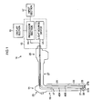
- Fig. 1 is an entire configuration diagram of an endoscope system according to an embodiment of the present invention.
- An endoscope system 10 illustrated in Fig. 1 is configured to include an endoscope body 11, a control apparatus 13 to which the endoscope body 11 is connected, a display section 15 and an input section 17.
- the endoscope body 11 is an electronic endoscope including an illumination optical system emitting illumination light from a leading end of an endoscope insertion part 19 to be inserted into an object, and an imaging optical system including an imaging element imaging an observed region.
- the endoscope body 11 includes an operation section 23 for bending operations of the leading end of the endoscope insertion part 19 and/or operations of suction, air supply/water supply and the like from the leading end of the endoscope insertion part 19, a connector section 25 that enables the endoscope body 11 to be detachably connected to the control apparatus 13, and a universal cord section 27 that joins the operation section 23 with the connector section 25.
- various kinds of channels such as a forceps channel for inserting a treatment tool for collecting tissue and the like and an air supply/water supply channel are provided.
- the endoscope insertion part 19 is configured of a flexible part 31 having flexibility, a bending part 33 to be bent according to bending operations and an endoscope leading end part 35. Note that the endoscope leading end part 35 is sometimes abbreviated as a "leading end part 35" in the following description.
- irradiation ports 37A and 37B through which light is applied to an observed region and an imaging element 21 obtaining image information of the observed region are disposed.
- the imaging element 21 employs a CCD (Charge Coupled Device) image sensor or a CMOS (Complementary Metal-Oxide Semiconductor) image sensor. To the imaging element 21, an imaging member 39 such as an objective lens is attached.
- CCD Charge Coupled Device
- CMOS Complementary Metal-Oxide Semiconductor
- the bending part 33 is provided between the flexible part 31 and leading end part 35 and is configured to be able to be freely bent according to wire operations from the operation section 23, actuation operations from an actuator, and the like.
- the bending part 33 can be bent in arbitrary directions and by arbitrary angles depending on portions of the object for which the endoscope body 11 is used, thereby enabling observation directions of the irradiation ports 37A and 37B and the imaging element 21 of the endoscope leading end part 35 to be directed toward desired observation portions.
- cover glasses and/or lenses are disposed.
- optical fibers 45A and 45B for guiding illumination light from a light source device 41 and a scope cable 47 connecting the imaging element 21 to a processor section 43 are inserted therethrough.
- various kinds of signal lines from the operation section 23 and various kinds of tubes such as air supply and water supply channels are also connected to the control apparatus 13 and the like through the universal cord section 27 and connector section 25.
- the connector section 25 illustrated in Fig. 1 is detachably connected to the control apparatus 13.
- the optical fibers 45A and 45B are connected to the light source device 41 in the control apparatus 13 through the connector section 25, and the scope cable 47 is connected to the processor section 43 in the control apparatus 13 through the connector section 25.
- the optical fibers 45A and 45B are connected to the light source device 41 by a connector section (not shown in Fig. 1 ; shown in Fig. 2 , accompanied by reference character 26A). Moreover, the scope cable 47 is connected to the processor section 43 by a connector section (not shown in Fig. 1 ; shown in Fig. 2 , accompanied by reference character 26B).
- control apparatus 13 includes the light source device 41 generating illumination light supplied to the irradiation ports 37A and 37B of the endoscope leading end part 35, and the processor section 43 that performs image processing on image signals from the imaging element 21.
- the processor section 43 performs image processing on imaging signals transmitted from the endoscope body 11, based on instructions from the operation section 23 of the endoscope body 11 or the input section 17, and generates an observation image to be displayed by the display section 15.
- Operation commands (operation command signals) sent from the input section 17 are sent to the processor section 43, and command signals corresponding to the operation signals are sent to the individual portions of the apparatus from the processor section 43.
- Exemplary configurations of the input section 17 can include a keyboard, a mouse, a joystick and the like.
- the display section 15 may be a touch-panel display apparatus, and buttons, switches and the like displayed on the display section 15 may constitute the input section 17.
- Fig. 2 is a block diagram of the endoscope system illustrated in Fig. 1 .
- elements same as or similar to those having been previously described are provided with the same reference characters and the description for those is omitted.
- the light source device 41 includes a blue laser light source 51 with a center wavelength of 445 nanometers and a violet laser light source 53 with a center wavelength of 405 nanometers as light-emitting sources. Light amounts from the blue laser light source 51 and violet laser light source 53 as semiconductor light-emitting elements (light amounts) are individually controlled by a light source control section 55.
- the blue laser light source 51 and violet laser light source 53 can employ InGaN-based laser diodes of a broad area type. Moreover, an InGaNAs-based laser diode and/or a GaNAs-based laser diode can also be employed. Furthermore, for the blue laser light source 51 and violet laser light source 53, there may be a configuration in which light-emitting bodies such as light-emitting diodes are used.
- Laser light emitted from the blue laser light source 51 and violet laser light source 53 is introduced into optical fibers (not shown) through collector lenses which are not shown, and transmitted to the endoscope leading end part 35 (see, Fig. 1 ) of the endoscope body 11 by the optical fibers 45A and 45B, respectively, through a connector section 26A and the connector section 25 on the endoscope body 11 side.
- the laser light emitted from the blue laser light source 51 is applied to a fluorescent material 57 as a wavelength conversion member disposed in the endoscope leading end part 35, and the laser light emitted from the violet laser light source 53 is applied to a light polarization/diffusion member 59.
- the not-shown optical fibers in the light source device 41 and the optical fibers 45A and 45B in the endoscope body 11 are multimode fibers, and as one example, thin cables each of which has a core diameter of 105 micrometers and a cladding diameter of 125 micrometers and whose diameter including a protective layer as an outer cover is ⁇ 0.3 millimeters to ⁇ 0.5 millimeters can be used.
- the fluorescent material 57 is configured to include a plurality of kinds of fluorescent materials which absorb part of blue laser light from the blue laser light source 51 and induce excited-light emission of green to yellow (for example, YAG-based (Yttrium Aluminum Garnet-based) fluorescent materials, fluorescent materials containing BAM (BaMgAl10O17) and the like, or the like).
- YAG-based fluorescent materials for example, Yttrium Aluminum Garnet-based fluorescent materials, fluorescent materials containing BAM (BaMgAl10O17) and the like, or the like.
- the endoscope system 10 presented in the example using a semiconductor light-emitting element as an excitation light source affords white light with high intensity in high light emission efficiency and the intensity of the white light can be easily adjusted. Furthermore, change in color temperature and chromaticity of the white light is small.
- the light polarization/diffusion member 59 is configured of material transmitting laser light from the violet laser light source 53, and for example, employs a resin material having transparency, glass, or the like. Furthermore, configurations of providing fine roughness on the surface or the like of the resin material or glass and/or providing a light diffusion layer in which particles (filler or the like) with different refractive indices are mixed thereon, or configurations of using translucent materials may be employed.
- Transmitted light emitted from the light polarization/diffusion member 59 is illumination light with a narrow-band wavelength (special light) whose light amount is uniform within a predetermined illumination region.
- Including the fluorescent material 57 and light polarization/diffusion member 59 can prevent phenomena of convolution of noise which disrupts imaging, occurrence of flickering in displaying a moving image, and the like, these caused by speckles arising from coherence of laser light.
- the fluorescent material 57 is preferable to be configured of material in which particle diameters of a fluorescent substance itself and a filler are set such that light in an infrared region is little absorbed and highly dispersed in consideration of a refractive index difference between the fluorescent substance constituting the fluorescent material and fixing and solidifying resin as the filler.
- a configuration of including the fluorescent material 57 can enhance a dispersion effect without decreasing the light intensity of red-band and/or infrared-band light and to make means for changing a light path such as a concave lens unnecessary, this reducing optical loss.
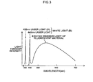
- Fig. 3 is a graph illustrating emission spectra of laser light from the violet laser light source 53, and blue laser light from the blue laser light source 51 and light after wavelength conversion on the blue laser light with the fluorescent material 57.
- the violet laser light from the violet laser light source 53 is indicated by an emission line with a center wavelength of 405 nanometers (profile A).
- the blue laser light from the blue laser light source 51 is indicated by an emission line with a center wavelength of 445 nanometers, and the excited emission light due to the blue laser light from the fluorescent material 57 presents a spectral intensity distribution in which the light amount increases in a wavelength band of 450 nanometers to 700 nanometers (profile B).
- the center wavelength of 405 nanometers for the violet laser light and the center wavelength of 445 nanometers for the blue laser light are representative and not limiting.
- Profile B constituted of the excited emission light and the blue laser light forms the white light.
- the "white light” in the present specification is not limited to the one strictly containing all the wavelength components in visible light, but for example, may be one containing light in specific wavelength bands such as R, G and B and may also include light containing wavelength components from green to red, light containing wavelength components from blue to green, or the like.
- the illumination light formed by the blue laser light source 51, fluorescent material 57 and violet laser light source 53 is applied toward an observed region of the object from the leading end part 35 of the endoscope body 11.
- the observed region to which the illumination light is applied is imaged on the imaging element 21 to be imaged as the observed region (object).
- An imaging signal obtained from the imaging element 21 by imaging the observed region is converted into a digital signal by an A/D converter 63 and sent to an image processing section 65 of the processor section 43.
- image processing section 65 image processing is performed on the inputted image signal in a digital form, an observation image which can be displayed on the display section 15 is generated and displayed on the display section 15. Moreover, it is printed by a recording apparatus (printer) 69 as needed.
- the recording apparatus 69 may be built in the processor section 43, or may be connected to the processor section 43 via a network.
- a memory apparatus such as a storage apparatus, a semiconductor memory medium and a magnetic memory medium may be included and the observation image may be stored therein as image data. Furthermore, associated with the observation image, additional information of the observation image may be stored along with the image data of the observation image.
- observation conditions such as an observation mode and an illumination mode (illumination conditions), imaging conditions of an imaging section (shown in Fig. 4 , accompanied by reference character 114) which includes the imaging element 21, an image processing mode, and other additional conditions are included.
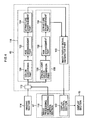
- Fig. 4 is a block diagram illustrating an exemplary configuration of the image processing section 65 and the periphery of the image processing section 65.
- the image processing section 65 presented in the example can perform changing between white light image processing (normal observation image processing) corresponding to a white light observation mode (normal observation mode) of using white light as illumination light and special light image processing corresponding to a special light observation mode of using special light.
- a control signal is sent from an image processing mode changing control section 110 of the control section 67 to an image processing mode changing section 112 of the image processing section 65.
- the image processing mode changing section 112 performs switching of an imaging signal obtained by an imaging section 114 to be sent to a white light image processing section 116 that performs the white light image processing or to be sent to a special light image processing section 118 that performs the special light image processing.
- the imaging section 114 illustrated in Fig. 4 includes the imaging lens 61 (optical system) and imaging element 21 illustrated in Fig. 2 , and in addition, includes a CDS circuit (not shown) performing correlated double sampling (CDS) on the imaging signal, an AGC circuit (not shown) performing automatic gain control (AGC), and the A/D converter 63 (see, Fig. 2 ) converting the analog signal having undergone the sampling and gain control into a digital signal.
- CDS circuit not shown
- AGC automatic gain control
- A/D converter 63 see, Fig. 2
- the white light image processing section 116 illustrated in Fig. 4 includes a color conversion part 120, a hue enhancement part 122 and a structure enhancement part 124, and performs processing on the imaging signal obtained in the white light observation mode and converted in a digital form.
- the color conversion part 120 performs gradation conversion processing and color conversion processing on a digital imaging signal for each of R, G and B to generate image data for each color of R, G and B. For example, in the image data for each color of R, G and B, with reference to a color conversion table, a gradation value is converted into a concentration value for each color of R, G and B.
- the hue enhancement part 122 performs hue enhancement processing of discriminating blood vessels from mucosa in the image regarding their shades to enhance the blood vessels so as to be seen easily, with respect to the image data for each color of R, G and B.
- hue enhancement processing can include processing of enhancing hue in a direction of discriminating blood vessels from mucosa regarding their shades over an average shade of the entire image in consideration of the average shade of the entire image (frame).
- the structure enhancement part 124 performs structure enhancement processing such as sharpness and edge enhancement on the image data for each color of R, G and B which data has undergone the hue enhancement processing.
- the image data for each color of R, G and B which data has undergone the structure enhancement processing performed by the structure enhancement part 124 is sent to an image display signal generation part 140.
- the special light image processing section 118 includes a special light color conversion part 130, a hue enhancement part 132 and a structure enhancement part 134, and performs processing on the imaging signal obtained in the special light observation mode.
- red (R) narrow-band light suitable for observation of a middle layer and a deep layer of body tissue is not used, but blue (B) narrow-band light suitable for observation of superficial layer tissue and green (G) narrow-band light suitable for observation of middle layer tissue and superficial layer tissue are used.
- G narrow-band data a G image signal (G narrow-band data) is multiplied by a predetermined coefficient and allocated to R image data
- B image signal B narrow-band data
- G image signal a B image signal
- B narrow-band data a predetermined coefficient and allocated to G image data
- B image data a predetermined coefficient and allocated to B image data
- the pseudo-color image thus generated contains much B image data mainly containing information of superficial layer tissue, it presents status of superficial layer tissue, micro blood vessels and/or microstructure more in detail, this enabling the micro blood vessels and/or microstructure of the superficial layer tissue to be observed easily.
- the special light color conversion part 130 performs gradation conversion processing and color conversion processing. After that, a G image signal is multiplied by a coefficient and allocated to R image data, and a B image signal is multiplied by a coefficient and allocated to G image data and B image data, these generating image data for each color of R, G and B.
- the hue enhancement part 132 performs processing of enhancement in a direction of discriminating blood vessels from mucosa in the image (frame) regarding their shades to enhance the blood vessels so as to be seen easily with respect to the image data for each color of R, G and B which data is generated by the special light color conversion part 130.
- the structure enhancement part 134 performs structure enhancement processing such as sharpness and edge enhancement on the image data for each color of R, G and B after the hue enhancement processing.
- the image data for each color of R, G and B which data has undergone the structure enhancement processing is sent to the image display signal generation part 140 as image data for each color of R, G and B which data has undergone the special light image processing.
- the image display signal generation part 140 converts the image data for each color of R, G and B generated by the processing in the parts of the white light image processing section 116 or the image data for each color of R, G and B generated by the processing in the parts of the special light image processing section 118 into an observation image data which can be displayed by the display section 15.
- the observation image data for display converted by the image display signal generation part 140 is sent to the display section 15 through the display control section 142 and displayed on the display section 15.
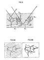
- Fig. 5 is an explanatory drawing schematically illustrating blood vessels in a mucosal surface of body tissue.
- the mucosal surface of body tissue is reported in which capillary blood vessels BL 2 such as a dendritic vascular network are formed to extend from a blood vessel BL 1 in deep mucosa to the mucosal surface, lesions of body tissue being exhibited in microstructure of the capillary blood vessels BL 2 and the like.
- the incident light diffusively propagates in the body tissue.
- the absorption/dispersion characteristics of body tissue have wavelength dependency and the dispersion characteristics tend to be stronger as the wavelength is shorter.
- a degree of light reaching a deep position changes according to an illumination light wavelength
- blood flowing in blood vessels has a local maximum of absorption in wavelengths of approximately 400 nanometers to 420 nanometers, this allowing large contrast.
- blood vessel information is obtained from capillary vessels in a mucosal surface, and when it is in a wavelength band ⁇ b with a wavelength of approximately 500 nanometers, blood vessel information including blood vessels in a deeper layer is obtained.
- a light source is used with a center wavelength not less than 360 nanometers and not more than 800 nanometers, preferably not less than 365 nanometers and not more than 515 nanometers, and further preferably, a center wavelength not less than 400 nanometers and not more than 470 nanometers.
- Figs. 6A and 6B are explanatory drawings of schematic display examples of observation images obtained by an endoscope system.
- Fig. 6A represents an observation image in a white light observation mode
- Fig. 6B represents an observation image in a special light observation mode.
- a mixing ratio between blue laser light with a center wavelength of approximately 445 nanometers (for example, 445 nanometers ⁇ 10 nanometers) from the blue laser light source 51 and violet laser light with a center wavelength of approximately 405 nanometers (for example, 405 nanometers ⁇ 10 nanometers) from the violet laser light source 53 can be adjusted by the light source control section 55 (see, Fig. 2 ).
- Examples of adjusting the mixing ratio between blue laser light and violet laser light can include an aspect of manipulating a switch 89 provided in the operation section 23 of the endoscope body 11 illustrated in Fig. 1 to perform image enhancement such that capillary vessels in a mucosal surface can be observed more easily.
- both of the blood vessel information obtained using blue laser light and the blood vessel information closer to the superficial layer obtained using violet laser light can be extracted and displaying them on the display section 15 (see, Fig. 1 ) enables the observer to compare both with each other.
- the blood vessel information containing the blood vessels closer to the superficial layer which cannot be observed using blue laser light can be observed in high visibility.
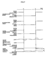
- Fig. 7 is an explanatory drawing of the observation mode changing according to a first embodiment.
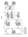
- Fig. 8 is a block diagram illustrating an exemplary configuration of the control section 67 and light source control section 55 according to the embodiment.
- Fig. 7 illustrates relationship between a changing command of an observation mode, changing timing of an illumination mode, changing timing of an image processing mode, an image signal (change in brightness of an observation image), and a light amount control signal.
- the light amount control signal illustrated in Fig. 7 represents a value in a control signal of the light amount of illumination light. Relationship between measurements of the light amount control signal represents relationship between measurements of the light amount of illumination light. In addition, the lateral series in Fig. 7 represents time and time elapses from left to right in the figure.
- a value A 1 of the light amount control signal of the illumination light used in the white light observation mode immediately before the changing timing t 1 of the observation mode is stored. Based on the stored value A 1 of the light amount control signal of the illumination light before changing, a value B 1 of the light amount control signal of the illumination light used in the special light observation mode after changing of the observation mode is calculated.
- the image signal (observation image) is prevented from being relatively dark at the changing timing t 1 of the observation mode.
- the illumination mode is changed from the special light mode to the white light mode and the image processing mode is changed from the special light image processing to the white light image processing.
- the image signal (observation image) is prevented from being relatively light at the changing timing t 2 of the observation mode.
- the broken lines illustrated for the image signal in Fig. 7 indicate that brightness of the image signal changes when the value of the light amount control signal of the illumination light is not changed before and after changing of the observation mode.
- Fig. 8 illustrates an exemplary configuration for realizing adjustment of the light amount of the illumination light upon the changing of the observation mode illustrated in Fig. 7 .
- control section 67 includes the image processing mode changing control section 110 (see, Fig. 2 ) and further includes an observation mode changing control section 200 and an illumination mode changing control section 202.
- an observation mode changing command signal is sent to the observation mode changing control section 200.
- a changing command signal of the image processing mode is sent to the image processing mode changing control section 110 and a changing command signal of the illumination mode is sent to the illumination mode changing control section 202, from the observation mode changing control section 200.
- a changing signal of the illumination mode is sent from the illumination mode changing control section 202 to the light source control section 55.
- a command signal of the image processing mode is sent from the image processing mode changing control section 110 to the image processing section 65.
- the light source control section 55 (see, Fig. 2 ) is configured to include a light amount conversion section 210, a light amount ratio storage section 212 and a light amount setting section 214.
- the light amount conversion section 210 calculates a setting value of the light amount of the illumination light immediately after changing of the observation mode (for example, B 1 in Fig. 7 ) from a setting value of the light amount of the illumination light immediately before changing of the observation mode (for example, A 1 in Fig. 7 ), and sends the setting value of the light amount of the illumination light immediately after changing of the observation mode to the light amount setting section 214.
- the light amount ratio storage section 212 stores light amount ratios between the observation modes (illumination modes) (for example, the constants k 1 and k 2 mentioned above).
- the light amount conversion section 210 refers to the light amount ratio stored in the light amount ratio storage section 212, and calculates the value of the light amount control signal of the illumination light used in the illumination mode after changing of the observation mode.
- the calculated value of the light amount control signal is sent to the light amount setting section 214, and based on the value of the light amount control signal, the light amounts of the blue laser light source 51 and violet laser light source 53 illustrated in Fig. 2 are set.
- the value of the light amount control signal is set to a ratio (0 percent to 100 percent) relative to the maximum value.
- the value of the light amount control signal of the illumination light used in the white light observation mode is 70 percent
- the value of the light amount control signal of the illumination light used in the special light observation mode after changing of the observation mode is set to a value exceeding 70 percent.
- the value of the light amount control signal of the illumination light used in the special light observation mode is 70 percent
- the value of the light amount control signal of the illumination light used in the white light observation mode after changing of the observation mode is set to a value less than 70 percent.
- This light amount control of the light source device 41 is only one example and the present invention can be applied to any other than the aspect of setting based on the ratio of the light amount control signal relative to the maximum value.
- the value of the light amount control signal of the illumination light used in the illumination mode after changing of the observation mode is determined in consideration of difference in light amount of the illumination light used in the illumination mode after changing of the observation mode. Therefore, brightness of the observation image (screen) does not change discontinuously before and after changing the observation mode.
- the light amount control signal after changing of the observation mode converges quickly.
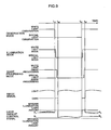
- Fig. 9 is an explanatory drawing of the observation mode changing according to the second embodiment
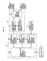
- Fig. 10 is a block diagram illustrating an exemplary configuration of the control section 67 and light source control section 55 according to the embodiment.
- changing of the observation mode, changing of the illumination mode and changing of the image processing mode are performed asynchronously.
- the illumination mode is changed from the white light mode to the special light mode and the image processing mode is changed from the white light image processing to the special light image processing.
- the value of the light amount control signal of the illumination light used in the special light mode is set as a preset fixed value (for example, the minimum value within the setting range).
- the "minimum value" noted herein may be zero as the light amount control signal (no light emission) or a minimum value which is not zero and is determined from observation conditions.
- the value of the light amount control signal is changed from the minimum value to B 1 .
- the illumination mode is changed from the special light mode to the white light mode and the image processing mode is changed from the special light image processing to the white light image processing.
- the light amount of the illumination light is set to the minimum value, and at the timing t 22 , the value of the light amount control signal of the illumination light used in the white light observation mode is changed from the minimum value to A 2 .
- a timer (delay time setting section) 203 that determines delay time from the changing timing of the observation mode is added.
- the timer 203 determines a period until the light amount of the light source device 41 is set to the minimum value from the changing timing of the observation mode (period from t 11 to t 12 ; period from t 21 to t 22 ).
- the delay time determined by the timer 203 may be adjusted according to the light amount setting value before changing or set to a fixed value.
- the delay time can be not more than 10 cycles of a changing interval of the observation image (not more than 10 frames in frame number of the observation image).
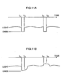
- Figs. 11A and 11B are explanatory drawings of an effect of the observation mode changing according to the second embodiment.
- Fig. 11A schematically illustrates an image signal (brightness of the observation image) in the observation mode changing according to the second embodiment.
- Fig. 11B schematically illustrates an image signal (brightness of the observation image) in case of no adjustment of the light amount of the illumination light in changing of the observation mode.
- brightness of the observation image fluctuates in changing of the observation mode.
- the light amount of the illumination light is set to the minimum value for a certain period, whereas the observation image immediately before the changing timing of the observation mode may be displayed for the relevant certain period.
- timing of changing of the illumination mode and timing of changing of the image processing mode may be determined arbitrarily.
- the image processing mode may be changed after changing of the illumination mode, or the illumination mode may be changed after changing of the image processing mode.
- the illumination mode and the image processing mode may be changed simultaneously.
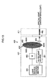
- Fig. 12 is a block diagram of a schematic configuration of an endoscope system 300 including a light source device 341.
- part of the configuration such as the processor section 43 (see, Fig. 2 ) is omitted from illustration.
- the light source device 341 of the endoscope system 300 illustrated in Fig. 12 employs a light source that emits broad (corresponding to broad-band) wavelength-band light such as a halogen lamp, a xenon lamp and a white light-emitting diode as a white light source 351.
- a light source that emits broad (corresponding to broad-band) wavelength-band light such as a halogen lamp, a xenon lamp and a white light-emitting diode as a white light source 351.
- White light emitted from the white light source 351 is applied toward the observed region from the leading end part (shown in Fig. 1 , accompanied by reference character 35) of an endoscope 311 through a light guide 345A as an optical fiber bundle.
- a special light source 353 illustrated in Fig. 12 employs the violet laser light source 53 illustrated in Fig. 1 .
- Special light emitted from the special light source 353 is sent to the leading end part of the endoscope 311 through a connector section 326 and an optical fiber 345B.
- the light polarization/diffusion member 359 may be replaced by a light emission window disposed in the leading end part of the endoscope body 11.
- white light that has broad spectroscopic characteristics corresponding to broad band and has a high color rendering property can be realized by a simple configuration, and in addition, heat generation of the endoscope leading end part is suppressed.
- white light and special light can be applied completely separately and narrow-band light is emitted onto the observed region not through the fluorescent material (shown in Fig. 2 , accompanied by reference numeral 57). Therefore, undesired light emission from the fluorescent material can be prevented and light amount control can be performed easily.
- Fig. 13 is a block diagram of an endoscope system 400 according to an aspect of a changed configuration of the special light source 353 in Fig. 12 .
- elements same as or similar to those in Fig. 12 are provided with the same reference characters and the description of those is omitted.
- an optical system for white light is omitted.
- a special light source that emits special light is omitted and narrow-band light (special light) is generated using the white light source 351 and optical filters 402 (402A, 402B and 402C).
- Light applied from the white light source 351 and transmitted through the optical filters 402 is guided to the light incident end of a light guide 454 through a condenser member 404 and guided to the leading end part of an endoscope 411 by the light guide 454.
- Each of the optical filters 402A, 402B and 402C is a narrow band-pass filter transmitting only predetermined narrow-band wavelength components in the incident white light and each of those corresponds to a different band from one another.
- the optical filters 402A, 402B and 402C are formed in part of a rotation filter plate 405 and any of the optical filters 402A, 402B and 402C can be selectively changed by driving and rotating the rotation filter plate 405 by means of a drive mechanism 406 including a motor and the like.
- the optical filters 402A, 402B and 402C which are two or more kinds are selectively switched and disposed in the middle of the light path of the white light, and thereby, special light corresponding to a plurality of kinds of narrow bands different from one another can be emitted.
- special light (narrow-band light) corresponding to arbitrary wavelength bands can be generated from the white light source.
- optical filters 402A, 402B and 402C illustrated in Fig. 13 being filters corresponding to R, G and B or another aspect of providing a filter corresponding to special light can be applied.
- the endoscope system presented in the example can employ a frame sequential imaging method using a light source device switching R, G and B sequentially for each frame or a light source device switching normal light and special light sequentially for each frame.
- the image processing mode may be switched in synchronization with switching of the illumination light or only has to be switched within preset delay time from the switching timing of the illumination light.
- An endoscope system including: an imaging section that images an observed region; an image processing section that generates an observation image of the observed region from an imaging signal obtained by the imaging section; a display section that displays the generated observation image; a light source section that selectively switches a plurality of kinds of illumination light different in spectroscopic characteristics to apply the illumination light to the observed region; an illumination mode changing section that changes the kind of illumination light applied from the light source section; and a light source control section that controls, based on a light amount control signal, a light amount of the illumination light emitted from the light source section, wherein the light source control section multiplies a value of the light amount control signal indicating a ratio relative to a maximum value of a light amount in an illumination mode before changing by a light amount ratio preset between different illumination modes to set a value of the light amount control signal for illumination light in an illumination mode after changing.
- the endoscope system according to the first aspect, further including an observation mode changing section that instructs changing of an observation mode including at least changing of the illumination mode by the illumination mode changing section, wherein the illumination mode changing section changes the illumination mode in synchronization with an observation mode changing instruction or after the observation mode changing instruction when the observation mode changing instruction is given by the observation mode changing section.
- the illumination mode is changed in synchronization with the changing instruction of the observation mode, brightness of the observation image is suppressed from being unstable before and after the observation mode changing.
- the endoscope system according to the second aspect or the third aspect, further including an image processing mode changing section that changes an image processing mode in the image processing section in synchronization with the observation mode changing instruction when the observation mode changing instruction is given by the observation mode changing section.
- the observation image can be obtained corresponding to the illumination mode after changing of the observation mode.
- the light amount of the illumination light is the fixed value during the period preset based on the changing instruction of the observation mode in the aspect of the illumination mode changed asynchronously with changing of the observation mode, brightness of the observation image is suppressed from discontinuously fluctuating caused by changing of the observation mode.
- the endoscope system according to the fifth aspect, further including an image processing mode changing section that changes an image processing mode in the image processing section in accordance with the illumination mode of the light source section, wherein the observation mode changing section instructs changing of the observation mode including changing of the image processing mode by the image processing mode changing section.
- the observation image can be obtained corresponding to the illumination mode after changing of the observation mode.
- the endoscope system according to any of the fifth aspect to the seventh aspect, further including a delay time setting section that sets, as the certain period, delay time after the observation mode changing instruction by the observation mode changing section.
- the light amount of the illumination light after changing of the illumination mode can be calculated easily.
- the aspect is preferable to calculate and store the light amount ratio for each observation mode.
- the light source section includes: a first light source that emits violet laser light with a center wavelength of 405 nanometers ⁇ 10 nanometers; a second light source that emits blue laser light with a center wavelength of 445 nanometers ⁇ 10 nanometers; and a fluorescent material inducing excited-light emission upon application of the blue laser light, and the light source control section sets, in a normal observation mode, light radiated from the fluorescent material upon light emission from the second light source, as the illumination light, and sets, in a special light observation mode, light emitted from the first light source upon light emission from the first light source, as the illumination light.
- the observation image corresponding to each illumination light can be obtained by configuring capable of switching the illumination light in the broad-band wavelength region and the illumination light in the narrow-band wavelength region.
Landscapes
- Life Sciences & Earth Sciences (AREA)
- Health & Medical Sciences (AREA)
- Surgery (AREA)
- Engineering & Computer Science (AREA)
- Biophysics (AREA)
- Biomedical Technology (AREA)
- Nuclear Medicine, Radiotherapy & Molecular Imaging (AREA)
- Optics & Photonics (AREA)
- Pathology (AREA)
- Radiology & Medical Imaging (AREA)
- Veterinary Medicine (AREA)
- Physics & Mathematics (AREA)
- Heart & Thoracic Surgery (AREA)
- Medical Informatics (AREA)
- Molecular Biology (AREA)
- Animal Behavior & Ethology (AREA)
- General Health & Medical Sciences (AREA)
- Public Health (AREA)
- Signal Processing (AREA)
- Endoscopes (AREA)
Applications Claiming Priority (1)
| Application Number | Priority Date | Filing Date | Title |
|---|---|---|---|
| JP2012164881A JP5677378B2 (ja) | 2012-07-25 | 2012-07-25 | 内視鏡システム |
Publications (2)
| Publication Number | Publication Date |
|---|---|
| EP2689713A1 EP2689713A1 (en) | 2014-01-29 |
| EP2689713B1 true EP2689713B1 (en) | 2015-09-02 |
Family
ID=48803467
Family Applications (1)
| Application Number | Title | Priority Date | Filing Date |
|---|---|---|---|
| EP13177528.0A Active EP2689713B1 (en) | 2012-07-25 | 2013-07-23 | Endoscope system |
Country Status (3)
| Country | Link |
|---|---|
| US (1) | US10299666B2 (enExample) |
| EP (1) | EP2689713B1 (enExample) |
| JP (1) | JP5677378B2 (enExample) |
Families Citing this family (16)
| Publication number | Priority date | Publication date | Assignee | Title |
|---|---|---|---|---|
| JP5677378B2 (ja) * | 2012-07-25 | 2015-02-25 | 富士フイルム株式会社 | 内視鏡システム |
| JP6284937B2 (ja) | 2012-07-26 | 2018-02-28 | デピュー シンセス プロダクツ, インコーポレーテッドDePuy Synthes Products, Inc. | 光が不十分な環境におけるYCbCrパルス照明システム |
| KR102278509B1 (ko) | 2012-07-26 | 2021-07-19 | 디퍼이 신테스 프로덕츠, 인코포레이티드 | 광 부족 환경에서 연속된 비디오 |
| AU2014233193B2 (en) | 2013-03-15 | 2018-11-01 | DePuy Synthes Products, Inc. | Controlling the integral light energy of a laser pulse |
| US10251530B2 (en) | 2013-03-15 | 2019-04-09 | DePuy Synthes Products, Inc. | Scope sensing in a light controlled environment |
| US9641815B2 (en) | 2013-03-15 | 2017-05-02 | DePuy Synthes Products, Inc. | Super resolution and color motion artifact correction in a pulsed color imaging system |
| CN114191114A (zh) | 2014-03-21 | 2022-03-18 | 德普伊新特斯产品公司 | 用于成像传感器的卡缘连接器 |
| EP3443925B1 (en) * | 2014-05-14 | 2021-02-24 | Stryker European Holdings I, LLC | Processor arrangement for tracking the position of a work target |
| CN107105982B (zh) * | 2015-10-30 | 2019-05-21 | 奥林巴斯株式会社 | 用于内窥镜系统的控制装置、内窥镜系统以及内窥镜系统的控制方法 |
| US10690904B2 (en) * | 2016-04-12 | 2020-06-23 | Stryker Corporation | Multiple imaging modality light source |
| WO2019039353A1 (ja) | 2017-08-22 | 2019-02-28 | 富士フイルム株式会社 | 光源装置、内視鏡システム、及び光源装置の作動方法 |
| JP7089943B2 (ja) * | 2018-05-25 | 2022-06-23 | オリンパス株式会社 | 内視鏡システム |
| JP7208876B2 (ja) * | 2019-09-11 | 2023-01-19 | 富士フイルム株式会社 | 内視鏡システム及びその作動方法 |
| WO2021199566A1 (ja) * | 2020-03-31 | 2021-10-07 | 富士フイルム株式会社 | 内視鏡システム、制御方法、及び制御プログラム |
| JP2022012599A (ja) * | 2020-07-02 | 2022-01-17 | ソニーグループ株式会社 | 医療システム、情報処理装置及び情報処理方法 |
| JP7670953B2 (ja) * | 2020-12-14 | 2025-05-01 | 日亜化学工業株式会社 | 光源装置および画像取得装置 |
Family Cites Families (35)
| Publication number | Priority date | Publication date | Assignee | Title |
|---|---|---|---|---|
| EP1383104B1 (en) * | 2001-04-25 | 2011-05-04 | Panasonic Corporation | Video display apparatus and video display method |
| US6960165B2 (en) * | 2001-05-16 | 2005-11-01 | Olympus Corporation | Endoscope with a single image pick-up element for fluorescent and normal-light images |
| US6617560B2 (en) * | 2001-05-30 | 2003-09-09 | Watt Stopper, Inc. | Lighting control circuit including LED for detecting exposure to radiation |
| JP2003075117A (ja) * | 2001-06-19 | 2003-03-12 | Omron Corp | 光学式センサ装置および光学式センサの信号処理装置ならびに光学式センサ用の分岐コネクタ |
| US20050154319A1 (en) * | 2002-01-15 | 2005-07-14 | Xillix Technologies Corporation | Fluorescence endoscopy video systems with no moving parts in the camera |
| JP3869324B2 (ja) | 2002-06-26 | 2007-01-17 | オリンパス株式会社 | 蛍光観察用画像処理装置 |
| JP3697256B2 (ja) * | 2003-02-12 | 2005-09-21 | キヤノン株式会社 | 撮像装置およびレンズ装置 |
| JP4554267B2 (ja) * | 2004-04-27 | 2010-09-29 | オリンパス株式会社 | 内視鏡及び内視鏡システム |
| EP1880658B9 (en) * | 2005-05-11 | 2013-04-17 | Olympus Medical Systems Corp. | Signal processing device for biological observation apparatus |
| JP4504324B2 (ja) * | 2005-05-13 | 2010-07-14 | オリンパスメディカルシステムズ株式会社 | 生体観測装置 |
| JP2006349731A (ja) * | 2005-06-13 | 2006-12-28 | Olympus Corp | 画像投影装置 |
| JP2007111357A (ja) * | 2005-10-21 | 2007-05-10 | Olympus Medical Systems Corp | 生体撮像装置及び生体観測システム |
| US20080177140A1 (en) * | 2007-01-23 | 2008-07-24 | Xillix Technologies Corp. | Cameras for fluorescence and reflectance imaging |
| JP5164473B2 (ja) * | 2007-08-10 | 2013-03-21 | オリンパスメディカルシステムズ株式会社 | 内視鏡装置 |
| JP5184016B2 (ja) * | 2007-09-12 | 2013-04-17 | オンセミコンダクター・トレーディング・リミテッド | 撮像装置 |
| JP5420168B2 (ja) | 2007-12-21 | 2014-02-19 | オリンパスメディカルシステムズ株式会社 | 光源装置および内視鏡装置 |
| JP5467756B2 (ja) * | 2008-11-14 | 2014-04-09 | Hoya株式会社 | 内視鏡装置 |
| JP5767775B2 (ja) | 2009-07-06 | 2015-08-19 | 富士フイルム株式会社 | 内視鏡装置 |
| JP5401205B2 (ja) * | 2009-08-10 | 2014-01-29 | 富士フイルム株式会社 | 内視鏡装置 |
| JP5460506B2 (ja) * | 2009-09-24 | 2014-04-02 | 富士フイルム株式会社 | 内視鏡装置の作動方法及び内視鏡装置 |
| JP5460507B2 (ja) * | 2009-09-24 | 2014-04-02 | 富士フイルム株式会社 | 内視鏡装置の作動方法及び内視鏡装置 |
| JP5606120B2 (ja) * | 2010-03-29 | 2014-10-15 | 富士フイルム株式会社 | 内視鏡装置 |
| JP2012000160A (ja) * | 2010-06-14 | 2012-01-05 | Fujifilm Corp | 内視鏡装置 |
| JP2012050641A (ja) | 2010-08-31 | 2012-03-15 | Fujifilm Corp | 内視鏡システム |
| JP5345597B2 (ja) * | 2010-09-27 | 2013-11-20 | 富士フイルム株式会社 | 温度調節装置および温度調節方法、光源装置ならびに内視鏡診断装置 |
| JP5371921B2 (ja) * | 2010-09-29 | 2013-12-18 | 富士フイルム株式会社 | 内視鏡装置 |
| JP5371920B2 (ja) * | 2010-09-29 | 2013-12-18 | 富士フイルム株式会社 | 内視鏡装置 |
| JP2012078503A (ja) * | 2010-09-30 | 2012-04-19 | Olympus Corp | 照明装置および観察システム |
| JP5258869B2 (ja) * | 2010-12-13 | 2013-08-07 | 富士フイルム株式会社 | 内視鏡装置 |
| JP5791269B2 (ja) * | 2010-12-14 | 2015-10-07 | キヤノン株式会社 | 画像形成装置 |
| JP5335017B2 (ja) * | 2011-02-24 | 2013-11-06 | 富士フイルム株式会社 | 内視鏡装置 |
| JP5816486B2 (ja) * | 2011-08-18 | 2015-11-18 | オリンパス株式会社 | 蛍光観察装置および蛍光観察システム並びに蛍光観察装置の蛍光画像処理方法 |
| JP2013252185A (ja) * | 2012-06-05 | 2013-12-19 | Canon Inc | 内視鏡及び内視鏡装置 |
| JP5677378B2 (ja) * | 2012-07-25 | 2015-02-25 | 富士フイルム株式会社 | 内視鏡システム |
| US9125274B1 (en) * | 2014-06-05 | 2015-09-01 | Osram Sylvania, Inc. | Lighting control techniques considering changes in eye sensitivity |
-
2012
- 2012-07-25 JP JP2012164881A patent/JP5677378B2/ja active Active
-
2013
- 2013-07-23 EP EP13177528.0A patent/EP2689713B1/en active Active
- 2013-07-24 US US13/949,474 patent/US10299666B2/en not_active Expired - Fee Related
Also Published As
| Publication number | Publication date |
|---|---|
| EP2689713A1 (en) | 2014-01-29 |
| JP2014023626A (ja) | 2014-02-06 |
| US10299666B2 (en) | 2019-05-28 |
| JP5677378B2 (ja) | 2015-02-25 |
| US20140031623A1 (en) | 2014-01-30 |
Similar Documents
| Publication | Publication Date | Title |
|---|---|---|
| EP2689713B1 (en) | Endoscope system | |
| EP2301416B1 (en) | Method of controlling endoscope and endoscope | |
| US8834359B2 (en) | Method of controlling endoscope and endoscope | |
| CN102204809B (zh) | 内窥镜设备 | |
| CN102469931B (zh) | 内窥镜用照明装置及内窥镜装置 | |
| EP2465431B1 (en) | Endoscope system and processor of endoscope system | |
| US20120154567A1 (en) | Endoscope apparatus | |
| EP3354188A1 (en) | Endoscope device | |
| US20120075449A1 (en) | Endoscope device | |
| JP6550420B2 (ja) | 内視鏡装置 | |
| JP5677555B2 (ja) | 内視鏡装置 | |
| JP6155367B2 (ja) | 内視鏡装置 | |
| JP2012110485A (ja) | 光源装置および内視鏡装置 | |
| JP5897663B2 (ja) | 内視鏡装置 | |
| JP2017200601A (ja) | 内視鏡装置 | |
| JP2017087078A (ja) | 内視鏡装置 | |
| JP6379260B2 (ja) | 内視鏡装置 | |
| JP2016105824A (ja) | 内視鏡装置 | |
| JP2015091351A (ja) | 内視鏡装置 | |
| JP6104419B2 (ja) | 内視鏡装置 | |
| JP2020078667A (ja) | 内視鏡装置 | |
| JP2014121630A (ja) | 内視鏡装置 |
Legal Events
| Date | Code | Title | Description |
|---|---|---|---|
| PUAI | Public reference made under article 153(3) epc to a published international application that has entered the european phase |
Free format text: ORIGINAL CODE: 0009012 |
|
| AK | Designated contracting states |
Kind code of ref document: A1 Designated state(s): AL AT BE BG CH CY CZ DE DK EE ES FI FR GB GR HR HU IE IS IT LI LT LU LV MC MK MT NL NO PL PT RO RS SE SI SK SM TR |
|
| AX | Request for extension of the european patent |
Extension state: BA ME |
|
| 17P | Request for examination filed |
Effective date: 20140205 |
|
| RBV | Designated contracting states (corrected) |
Designated state(s): AL AT BE BG CH CY CZ DE DK EE ES FI FR GB GR HR HU IE IS IT LI LT LU LV MC MK MT NL NO PL PT RO RS SE SI SK SM TR |
|
| RIC1 | Information provided on ipc code assigned before grant |
Ipc: A61B 1/00 20060101AFI20150112BHEP Ipc: A61B 1/06 20060101ALI20150112BHEP |
|
| GRAP | Despatch of communication of intention to grant a patent |
Free format text: ORIGINAL CODE: EPIDOSNIGR1 |
|
| INTG | Intention to grant announced |
Effective date: 20150320 |
|
| GRAS | Grant fee paid |
Free format text: ORIGINAL CODE: EPIDOSNIGR3 |
|
| GRAA | (expected) grant |
Free format text: ORIGINAL CODE: 0009210 |
|
| AK | Designated contracting states |
Kind code of ref document: B1 Designated state(s): AL AT BE BG CH CY CZ DE DK EE ES FI FR GB GR HR HU IE IS IT LI LT LU LV MC MK MT NL NO PL PT RO RS SE SI SK SM TR |
|
| REG | Reference to a national code |
Ref country code: GB Ref legal event code: FG4D |
|
| REG | Reference to a national code |
Ref country code: AT Ref legal event code: REF Ref document number: 746014 Country of ref document: AT Kind code of ref document: T Effective date: 20150915 Ref country code: CH Ref legal event code: EP |
|
| REG | Reference to a national code |
Ref country code: IE Ref legal event code: FG4D |
|
| REG | Reference to a national code |
Ref country code: DE Ref legal event code: R096 Ref document number: 602013002803 Country of ref document: DE |
|
| REG | Reference to a national code |
Ref country code: AT Ref legal event code: MK05 Ref document number: 746014 Country of ref document: AT Kind code of ref document: T Effective date: 20150902 |
|
| PG25 | Lapsed in a contracting state [announced via postgrant information from national office to epo] |
Ref country code: NO Free format text: LAPSE BECAUSE OF FAILURE TO SUBMIT A TRANSLATION OF THE DESCRIPTION OR TO PAY THE FEE WITHIN THE PRESCRIBED TIME-LIMIT Effective date: 20151202 Ref country code: LT Free format text: LAPSE BECAUSE OF FAILURE TO SUBMIT A TRANSLATION OF THE DESCRIPTION OR TO PAY THE FEE WITHIN THE PRESCRIBED TIME-LIMIT Effective date: 20150902 Ref country code: LV Free format text: LAPSE BECAUSE OF FAILURE TO SUBMIT A TRANSLATION OF THE DESCRIPTION OR TO PAY THE FEE WITHIN THE PRESCRIBED TIME-LIMIT Effective date: 20150902 Ref country code: GR Free format text: LAPSE BECAUSE OF FAILURE TO SUBMIT A TRANSLATION OF THE DESCRIPTION OR TO PAY THE FEE WITHIN THE PRESCRIBED TIME-LIMIT Effective date: 20151203 Ref country code: FI Free format text: LAPSE BECAUSE OF FAILURE TO SUBMIT A TRANSLATION OF THE DESCRIPTION OR TO PAY THE FEE WITHIN THE PRESCRIBED TIME-LIMIT Effective date: 20150902 |
|
| REG | Reference to a national code |
Ref country code: LT Ref legal event code: MG4D Ref country code: NL Ref legal event code: MP Effective date: 20150902 |
|
| PG25 | Lapsed in a contracting state [announced via postgrant information from national office to epo] |
Ref country code: SE Free format text: LAPSE BECAUSE OF FAILURE TO SUBMIT A TRANSLATION OF THE DESCRIPTION OR TO PAY THE FEE WITHIN THE PRESCRIBED TIME-LIMIT Effective date: 20150902 Ref country code: PL Free format text: LAPSE BECAUSE OF FAILURE TO SUBMIT A TRANSLATION OF THE DESCRIPTION OR TO PAY THE FEE WITHIN THE PRESCRIBED TIME-LIMIT Effective date: 20150902 Ref country code: AT Free format text: LAPSE BECAUSE OF FAILURE TO SUBMIT A TRANSLATION OF THE DESCRIPTION OR TO PAY THE FEE WITHIN THE PRESCRIBED TIME-LIMIT Effective date: 20150902 Ref country code: ES Free format text: LAPSE BECAUSE OF FAILURE TO SUBMIT A TRANSLATION OF THE DESCRIPTION OR TO PAY THE FEE WITHIN THE PRESCRIBED TIME-LIMIT Effective date: 20150902 Ref country code: RS Free format text: LAPSE BECAUSE OF FAILURE TO SUBMIT A TRANSLATION OF THE DESCRIPTION OR TO PAY THE FEE WITHIN THE PRESCRIBED TIME-LIMIT Effective date: 20150902 |
|
| PG25 | Lapsed in a contracting state [announced via postgrant information from national office to epo] |
Ref country code: IT Free format text: LAPSE BECAUSE OF FAILURE TO SUBMIT A TRANSLATION OF THE DESCRIPTION OR TO PAY THE FEE WITHIN THE PRESCRIBED TIME-LIMIT Effective date: 20150902 Ref country code: SK Free format text: LAPSE BECAUSE OF FAILURE TO SUBMIT A TRANSLATION OF THE DESCRIPTION OR TO PAY THE FEE WITHIN THE PRESCRIBED TIME-LIMIT Effective date: 20150902 Ref country code: EE Free format text: LAPSE BECAUSE OF FAILURE TO SUBMIT A TRANSLATION OF THE DESCRIPTION OR TO PAY THE FEE WITHIN THE PRESCRIBED TIME-LIMIT Effective date: 20150902 Ref country code: CZ Free format text: LAPSE BECAUSE OF FAILURE TO SUBMIT A TRANSLATION OF THE DESCRIPTION OR TO PAY THE FEE WITHIN THE PRESCRIBED TIME-LIMIT Effective date: 20150902 Ref country code: NL Free format text: LAPSE BECAUSE OF FAILURE TO SUBMIT A TRANSLATION OF THE DESCRIPTION OR TO PAY THE FEE WITHIN THE PRESCRIBED TIME-LIMIT Effective date: 20150902 Ref country code: IS Free format text: LAPSE BECAUSE OF FAILURE TO SUBMIT A TRANSLATION OF THE DESCRIPTION OR TO PAY THE FEE WITHIN THE PRESCRIBED TIME-LIMIT Effective date: 20160102 |
|
| PG25 | Lapsed in a contracting state [announced via postgrant information from national office to epo] |
Ref country code: RO Free format text: LAPSE BECAUSE OF FAILURE TO SUBMIT A TRANSLATION OF THE DESCRIPTION OR TO PAY THE FEE WITHIN THE PRESCRIBED TIME-LIMIT Effective date: 20150902 Ref country code: PT Free format text: LAPSE BECAUSE OF FAILURE TO SUBMIT A TRANSLATION OF THE DESCRIPTION OR TO PAY THE FEE WITHIN THE PRESCRIBED TIME-LIMIT Effective date: 20160104 |
|
| REG | Reference to a national code |
Ref country code: DE Ref legal event code: R097 Ref document number: 602013002803 Country of ref document: DE |
|
| REG | Reference to a national code |
Ref country code: FR Ref legal event code: PLFP Year of fee payment: 4 |
|
| PLBE | No opposition filed within time limit |
Free format text: ORIGINAL CODE: 0009261 |
|
| STAA | Information on the status of an ep patent application or granted ep patent |
Free format text: STATUS: NO OPPOSITION FILED WITHIN TIME LIMIT |
|
| 26N | No opposition filed |
Effective date: 20160603 |
|
| PG25 | Lapsed in a contracting state [announced via postgrant information from national office to epo] |
Ref country code: SI Free format text: LAPSE BECAUSE OF FAILURE TO SUBMIT A TRANSLATION OF THE DESCRIPTION OR TO PAY THE FEE WITHIN THE PRESCRIBED TIME-LIMIT Effective date: 20150902 Ref country code: DK Free format text: LAPSE BECAUSE OF FAILURE TO SUBMIT A TRANSLATION OF THE DESCRIPTION OR TO PAY THE FEE WITHIN THE PRESCRIBED TIME-LIMIT Effective date: 20150902 |
|
| PG25 | Lapsed in a contracting state [announced via postgrant information from national office to epo] |
Ref country code: BE Free format text: LAPSE BECAUSE OF FAILURE TO SUBMIT A TRANSLATION OF THE DESCRIPTION OR TO PAY THE FEE WITHIN THE PRESCRIBED TIME-LIMIT Effective date: 20150902 |
|
| REG | Reference to a national code |
Ref country code: CH Ref legal event code: PL |
|
| PG25 | Lapsed in a contracting state [announced via postgrant information from national office to epo] |
Ref country code: MC Free format text: LAPSE BECAUSE OF FAILURE TO SUBMIT A TRANSLATION OF THE DESCRIPTION OR TO PAY THE FEE WITHIN THE PRESCRIBED TIME-LIMIT Effective date: 20150902 |
|
| PG25 | Lapsed in a contracting state [announced via postgrant information from national office to epo] |
Ref country code: LI Free format text: LAPSE BECAUSE OF NON-PAYMENT OF DUE FEES Effective date: 20160731 Ref country code: CH Free format text: LAPSE BECAUSE OF NON-PAYMENT OF DUE FEES Effective date: 20160731 |
|
| REG | Reference to a national code |
Ref country code: IE Ref legal event code: MM4A |
|
| REG | Reference to a national code |
Ref country code: FR Ref legal event code: PLFP Year of fee payment: 5 |
|
| PG25 | Lapsed in a contracting state [announced via postgrant information from national office to epo] |
Ref country code: IE Free format text: LAPSE BECAUSE OF NON-PAYMENT OF DUE FEES Effective date: 20160723 |
|
| PG25 | Lapsed in a contracting state [announced via postgrant information from national office to epo] |
Ref country code: LU Free format text: LAPSE BECAUSE OF NON-PAYMENT OF DUE FEES Effective date: 20160723 |
|
| PG25 | Lapsed in a contracting state [announced via postgrant information from national office to epo] |
Ref country code: SM Free format text: LAPSE BECAUSE OF FAILURE TO SUBMIT A TRANSLATION OF THE DESCRIPTION OR TO PAY THE FEE WITHIN THE PRESCRIBED TIME-LIMIT Effective date: 20150902 Ref country code: HU Free format text: LAPSE BECAUSE OF FAILURE TO SUBMIT A TRANSLATION OF THE DESCRIPTION OR TO PAY THE FEE WITHIN THE PRESCRIBED TIME-LIMIT; INVALID AB INITIO Effective date: 20130723 Ref country code: CY Free format text: LAPSE BECAUSE OF FAILURE TO SUBMIT A TRANSLATION OF THE DESCRIPTION OR TO PAY THE FEE WITHIN THE PRESCRIBED TIME-LIMIT Effective date: 20150902 |
|
| REG | Reference to a national code |
Ref country code: FR Ref legal event code: PLFP Year of fee payment: 6 |
|
| PG25 | Lapsed in a contracting state [announced via postgrant information from national office to epo] |
Ref country code: MK Free format text: LAPSE BECAUSE OF FAILURE TO SUBMIT A TRANSLATION OF THE DESCRIPTION OR TO PAY THE FEE WITHIN THE PRESCRIBED TIME-LIMIT Effective date: 20150902 Ref country code: HR Free format text: LAPSE BECAUSE OF FAILURE TO SUBMIT A TRANSLATION OF THE DESCRIPTION OR TO PAY THE FEE WITHIN THE PRESCRIBED TIME-LIMIT Effective date: 20150902 Ref country code: TR Free format text: LAPSE BECAUSE OF FAILURE TO SUBMIT A TRANSLATION OF THE DESCRIPTION OR TO PAY THE FEE WITHIN THE PRESCRIBED TIME-LIMIT Effective date: 20150902 Ref country code: MT Free format text: LAPSE BECAUSE OF NON-PAYMENT OF DUE FEES Effective date: 20160731 |
|
| PG25 | Lapsed in a contracting state [announced via postgrant information from national office to epo] |
Ref country code: BG Free format text: LAPSE BECAUSE OF FAILURE TO SUBMIT A TRANSLATION OF THE DESCRIPTION OR TO PAY THE FEE WITHIN THE PRESCRIBED TIME-LIMIT Effective date: 20150902 |
|
| PG25 | Lapsed in a contracting state [announced via postgrant information from national office to epo] |
Ref country code: AL Free format text: LAPSE BECAUSE OF FAILURE TO SUBMIT A TRANSLATION OF THE DESCRIPTION OR TO PAY THE FEE WITHIN THE PRESCRIBED TIME-LIMIT Effective date: 20150902 |
|
| PGFP | Annual fee paid to national office [announced via postgrant information from national office to epo] |
Ref country code: FR Payment date: 20200612 Year of fee payment: 8 |
|
| PGFP | Annual fee paid to national office [announced via postgrant information from national office to epo] |
Ref country code: GB Payment date: 20200716 Year of fee payment: 8 |
|
| GBPC | Gb: european patent ceased through non-payment of renewal fee |
Effective date: 20210723 |
|
| PG25 | Lapsed in a contracting state [announced via postgrant information from national office to epo] |
Ref country code: GB Free format text: LAPSE BECAUSE OF NON-PAYMENT OF DUE FEES Effective date: 20210723 |
|
| PG25 | Lapsed in a contracting state [announced via postgrant information from national office to epo] |
Ref country code: FR Free format text: LAPSE BECAUSE OF NON-PAYMENT OF DUE FEES Effective date: 20210731 |
|
| P01 | Opt-out of the competence of the unified patent court (upc) registered |
Effective date: 20230515 |
|
| PGFP | Annual fee paid to national office [announced via postgrant information from national office to epo] |
Ref country code: DE Payment date: 20250528 Year of fee payment: 13 |