EP2684610B2 - Pomme de douche - Google Patents
Pomme de douche Download PDFInfo
- Publication number
- EP2684610B2 EP2684610B2 EP13174601.8A EP13174601A EP2684610B2 EP 2684610 B2 EP2684610 B2 EP 2684610B2 EP 13174601 A EP13174601 A EP 13174601A EP 2684610 B2 EP2684610 B2 EP 2684610B2
- Authority
- EP
- European Patent Office
- Prior art keywords
- jet
- outlet openings
- chamber
- jet outlet
- chambers
- Prior art date
- Legal status (The legal status is an assumption and is not a legal conclusion. Google has not performed a legal analysis and makes no representation as to the accuracy of the status listed.)
- Active
Links
- XLYOFNOQVPJJNP-UHFFFAOYSA-N water Substances O XLYOFNOQVPJJNP-UHFFFAOYSA-N 0.000 claims description 50
- 210000002445 nipple Anatomy 0.000 claims description 36
- 238000005192 partition Methods 0.000 claims description 19
- 239000000463 material Substances 0.000 claims description 3
- 230000015572 biosynthetic process Effects 0.000 claims 2
- 210000003739 neck Anatomy 0.000 claims 2
- 238000007599 discharging Methods 0.000 claims 1
- 229920001971 elastomer Polymers 0.000 claims 1
- 239000000806 elastomer Substances 0.000 claims 1
- 239000013536 elastomeric material Substances 0.000 description 6
- 238000011161 development Methods 0.000 description 4
- 230000018109 developmental process Effects 0.000 description 4
- 230000002262 irrigation Effects 0.000 description 4
- 238000003973 irrigation Methods 0.000 description 4
- 230000002093 peripheral effect Effects 0.000 description 2
- 230000000284 resting effect Effects 0.000 description 2
- 239000007921 spray Substances 0.000 description 2
- 238000004891 communication Methods 0.000 description 1
- 239000012530 fluid Substances 0.000 description 1
- 230000003993 interaction Effects 0.000 description 1
- 230000001105 regulatory effect Effects 0.000 description 1
- 210000003813 thumb Anatomy 0.000 description 1
- 230000007704 transition Effects 0.000 description 1
- 238000011144 upstream manufacturing Methods 0.000 description 1
Images


Classifications
-
- B—PERFORMING OPERATIONS; TRANSPORTING
- B05—SPRAYING OR ATOMISING IN GENERAL; APPLYING FLUENT MATERIALS TO SURFACES, IN GENERAL
- B05B—SPRAYING APPARATUS; ATOMISING APPARATUS; NOZZLES
- B05B1/00—Nozzles, spray heads or other outlets, with or without auxiliary devices such as valves, heating means
- B05B1/14—Nozzles, spray heads or other outlets, with or without auxiliary devices such as valves, heating means with multiple outlet openings; with strainers in or outside the outlet opening
- B05B1/16—Nozzles, spray heads or other outlets, with or without auxiliary devices such as valves, heating means with multiple outlet openings; with strainers in or outside the outlet opening having selectively- effective outlets
-
- B—PERFORMING OPERATIONS; TRANSPORTING
- B05—SPRAYING OR ATOMISING IN GENERAL; APPLYING FLUENT MATERIALS TO SURFACES, IN GENERAL
- B05B—SPRAYING APPARATUS; ATOMISING APPARATUS; NOZZLES
- B05B1/00—Nozzles, spray heads or other outlets, with or without auxiliary devices such as valves, heating means
- B05B1/14—Nozzles, spray heads or other outlets, with or without auxiliary devices such as valves, heating means with multiple outlet openings; with strainers in or outside the outlet opening
- B05B1/18—Roses; Shower heads
-
- A—HUMAN NECESSITIES
- A47—FURNITURE; DOMESTIC ARTICLES OR APPLIANCES; COFFEE MILLS; SPICE MILLS; SUCTION CLEANERS IN GENERAL
- A47K—SANITARY EQUIPMENT NOT OTHERWISE PROVIDED FOR; TOILET ACCESSORIES
- A47K3/00—Baths; Douches; Appurtenances therefor
- A47K3/28—Showers or bathing douches
-
- B—PERFORMING OPERATIONS; TRANSPORTING
- B05—SPRAYING OR ATOMISING IN GENERAL; APPLYING FLUENT MATERIALS TO SURFACES, IN GENERAL
- B05B—SPRAYING APPARATUS; ATOMISING APPARATUS; NOZZLES
- B05B1/00—Nozzles, spray heads or other outlets, with or without auxiliary devices such as valves, heating means
- B05B1/14—Nozzles, spray heads or other outlets, with or without auxiliary devices such as valves, heating means with multiple outlet openings; with strainers in or outside the outlet opening
- B05B1/16—Nozzles, spray heads or other outlets, with or without auxiliary devices such as valves, heating means with multiple outlet openings; with strainers in or outside the outlet opening having selectively- effective outlets
- B05B1/1609—Nozzles, spray heads or other outlets, with or without auxiliary devices such as valves, heating means with multiple outlet openings; with strainers in or outside the outlet opening having selectively- effective outlets with a selecting mechanism comprising a lift valve
-
- B—PERFORMING OPERATIONS; TRANSPORTING
- B05—SPRAYING OR ATOMISING IN GENERAL; APPLYING FLUENT MATERIALS TO SURFACES, IN GENERAL
- B05B—SPRAYING APPARATUS; ATOMISING APPARATUS; NOZZLES
- B05B1/00—Nozzles, spray heads or other outlets, with or without auxiliary devices such as valves, heating means
- B05B1/14—Nozzles, spray heads or other outlets, with or without auxiliary devices such as valves, heating means with multiple outlet openings; with strainers in or outside the outlet opening
- B05B1/16—Nozzles, spray heads or other outlets, with or without auxiliary devices such as valves, heating means with multiple outlet openings; with strainers in or outside the outlet opening having selectively- effective outlets
- B05B1/1627—Nozzles, spray heads or other outlets, with or without auxiliary devices such as valves, heating means with multiple outlet openings; with strainers in or outside the outlet opening having selectively- effective outlets with a selecting mechanism comprising a gate valve, a sliding valve or a cock
- B05B1/1636—Nozzles, spray heads or other outlets, with or without auxiliary devices such as valves, heating means with multiple outlet openings; with strainers in or outside the outlet opening having selectively- effective outlets with a selecting mechanism comprising a gate valve, a sliding valve or a cock by relative rotative movement of the valve elements
-
- B—PERFORMING OPERATIONS; TRANSPORTING
- B05—SPRAYING OR ATOMISING IN GENERAL; APPLYING FLUENT MATERIALS TO SURFACES, IN GENERAL
- B05B—SPRAYING APPARATUS; ATOMISING APPARATUS; NOZZLES
- B05B1/00—Nozzles, spray heads or other outlets, with or without auxiliary devices such as valves, heating means
- B05B1/14—Nozzles, spray heads or other outlets, with or without auxiliary devices such as valves, heating means with multiple outlet openings; with strainers in or outside the outlet opening
- B05B1/16—Nozzles, spray heads or other outlets, with or without auxiliary devices such as valves, heating means with multiple outlet openings; with strainers in or outside the outlet opening having selectively- effective outlets
- B05B1/1681—Nozzles, spray heads or other outlets, with or without auxiliary devices such as valves, heating means with multiple outlet openings; with strainers in or outside the outlet opening having selectively- effective outlets with a selecting mechanism comprising a gate valve, sliding valve or cock and a lift valve
-
- B—PERFORMING OPERATIONS; TRANSPORTING
- B05—SPRAYING OR ATOMISING IN GENERAL; APPLYING FLUENT MATERIALS TO SURFACES, IN GENERAL
- B05B—SPRAYING APPARATUS; ATOMISING APPARATUS; NOZZLES
- B05B1/00—Nozzles, spray heads or other outlets, with or without auxiliary devices such as valves, heating means
- B05B1/30—Nozzles, spray heads or other outlets, with or without auxiliary devices such as valves, heating means designed to control volume of flow, e.g. with adjustable passages
- B05B1/3006—Nozzles, spray heads or other outlets, with or without auxiliary devices such as valves, heating means designed to control volume of flow, e.g. with adjustable passages the controlling element being actuated by the pressure of the fluid to be sprayed
-
- B—PERFORMING OPERATIONS; TRANSPORTING
- B05—SPRAYING OR ATOMISING IN GENERAL; APPLYING FLUENT MATERIALS TO SURFACES, IN GENERAL
- B05B—SPRAYING APPARATUS; ATOMISING APPARATUS; NOZZLES
- B05B12/00—Arrangements for controlling delivery; Arrangements for controlling the spray area
- B05B12/002—Manually-actuated controlling means, e.g. push buttons, levers or triggers
Definitions
- the invention relates to a shower head, for example a hand shower or an overhead shower, with a shower head housing which has a jet disk with several groups of jet outlet openings.
- the jet outlet openings are arranged, for example, in concentric rings, the different jet types being combined in such a way that one ring emits one type of jets and the next ring emits the other type of jets.
- annular chambers are arranged behind the jet disk, each of which extends to the rear of the jet disk. It is therefore an arrangement of the chambers next to one another.
- the spray disc has three concentric circular rings of spray outlets.
- a middle ring emits aerated jets
- an inner ring emits massage jets
- an outer ring emits a conical jet.
- a shower head of a similar type in which a first irrigation chamber with an associated set of first water outlets is separated by an annular partition wall from a second irrigation chamber with an associated set of second water outlets.
- the two irrigation chambers adjoining a jet outlet disc with the water outlets are preceded by a water dividing element which has two water dividing openings, one of which can be switched to open and the other to be closed, in order to dispense water that is supplied via an inlet channel into an antechamber in front of the water dividing openings. switchable to supply the first or the second irrigation chamber.
- the invention is based on the object of creating a shower of the type mentioned, in which the exit jets can be distributed as evenly as possible over the entire exit surface of the jet disc, so that the overall image is changed as little as possible when switching between different jets the shower head housing can be produced with relatively little effort.
- the shower head can be a hand shower, an overhead shower or a side shower.
- the shower head housing therefore contains at least two chambers that are responsible for the water supply to the jet outlet openings. At least one of these two chambers is responsible for the water supply exclusively to a group of jet outlets in the jet disc.
- the arrangement of the two chambers one behind the other has the advantage that the effort for creating the shower head housing is low and it is therefore relatively easy to distribute the associated outlet jets evenly over the outlet surface of the jet disc.
- the jet outlet openings are formed by nipples made of elastomeric material, which are molded onto a common plate made of this material that rests on the inside of the jet disc.
- the nipples preferably emerge from the jet disc at the front by a certain distance.
- the other chamber can supply both groups of jet outlet openings with water.
- the jet outlet openings of a group of jet outlet openings are connected through channels to a rear one of the chambers which pass through a front one of the chambers.
- the water comes out of the rear chamber through a separate channel for each jet outlet opening shower out.
- nozzles formed on a partition between the two chambers engage in the nipples, which are optionally lengthened on their inside, whereby these nozzles form the channels through which the water from the rear chamber reaches the jet outlet openings of the jet disc.
- a rear one of the chambers has its own jet outlet openings which are aligned concentrically with respect to jet outlet openings of the jet disc and have a smaller diameter.
- the water emerging from the rear chamber thus emerges as individual jets which traverse a front of the chambers and only emerge through those jet outlet openings which are assigned to the rear chamber.
- the rear chamber's own jet outlet openings are formed by nozzles which are molded onto a partition between the front and rear chambers.
- both chambers are exclusively responsible for the water supply to one group of jet outlet openings.
- one chamber is arranged directly behind the jet disk so that a group of jet outlet openings leads directly into this chamber, which is arranged behind the jet disk and is thus designated as the front chamber.
- the shower head can have a manually operable switchover valve in order to bring one of the two chambers into connection with the water inlet in the shower head housing. This allows you to choose between the different water jets be switched, which is particularly useful when it comes to different types of water jets.
- the switch valve in such a way that it also includes the possibility of supplying water to both chambers at the same time.
- Such a possibility is also useful if the two groups of jet outlet openings emit the same type of water jets. In this way, the amount of water to be dispensed can be regulated to a certain extent.
- the jet outlet openings of both groups of jet outlet openings are arranged in the jet disk in a mixed manner or evenly distributed.
- the jet outlet openings of both groups of jet outlet openings are identical, in particular if the switching valve is to be used to switch between the supply of one group on the one hand and the supply of both groups at the same time. Then the supply of only one group of jet outlets can be viewed as an economy circuit.
- jet outlet openings of both groups are designed to deliver different jet types.
- the jet outlet openings of a group are identical to one another or emit the same type of jets.
- these nipples are extended within the first chamber on the rear side of the plate resting against the jet disk and form a connecting piece there.
- the shower head housing can also have, for example in the middle, a device for forming massage jets which contains a further chamber for supplying water.
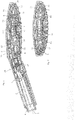
- FIG. 1 shows a longitudinal section through a hand shower.
- the hand shower contains a handle 1 which is attached to a shower head housing 2. At the end of the handle 1 there is a water inlet 3. A union nut of a shower hose can be screwed onto an external thread 4 of a channel 5.
- the shower head housing 2 contains a rear wall 6 and opposite this a jet disk 7.
- a jet disk 7 In the jet disk 7 there are a plurality of jet outlet openings 8 and 8a, which are formed by nipples 9, 17 made of elastomeric material.
- the nipples 9, 17 are formed on a flat element 10, which is on the inside the jet disk 7 is applied.
- the nipples 9, 17 protrude somewhat beyond the outside of the jet disk 7, so they protrude somewhat. They contain a passage 11 in their interior.
- the openings 8 and 8a are evenly distributed over the entire surface of the jet disk, the openings 8 corresponding to the nipples 9 and the openings 8a to the nipples 17 corresponding.
- a first chamber 12 is formed, from which the nipples 9 lead out.
- the chamber 12 is delimited by a partition 13 running approximately parallel to the jet disk 7.
- a water duct leads into the chamber 12 through a channel 14.
- a switch valve 15 is arranged, which is operated with the aid of a button 16.
- the button 16 is arranged in the transition area between the handle 1 and the jet disk 7 so that a user can operate it with the thumb of the hand with which he is holding the shower head.
- the nipples 17 protrude from the jet disk 7 in addition to the nipples 9 and, in contrast to the nipples 9, form an extension 18 on the rear side of the plate 10 facing away from the jet disk 7.
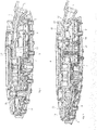
- a further chamber 21 is formed behind the partition 13, which, depending on the position of the switching valve 15, can also be connected to the water supply. If the chamber 21 is connected to the inlet 3, the water from the second chamber 21 reaches the nipple 17 via the nozzle 19 and then exits the jet disk 7 through this nipple 17 or the associated openings 8.
- this second chamber 21 can also be seen, as well as the different types of nipples 9 and 17, respectively.
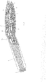
- FIG. 3 a section is shown in which the water guide is connected to the rear chamber 21 via a section 23. In this position of the switching valve 15, the water only exits through the nipple 17 connected to the rear chamber 21.
- the front chamber 12 is not connected to the water inlet 3, so that no water emerges from the jet outlet openings 8a assigned to the front chamber.
- the jet outlet openings 8a, 8 are each assigned to only one chamber 12 and 21, respectively.
- Each jet outlet opening is therefore assigned either to the front chamber 12, that is to say to the chamber arranged closer to the jet disk 7, or to the rear chamber 21, which is separated from the front chamber by the partition 13.
- the chambers 12, 21 are fluidically coupled in parallel to the water inlet 3 via the water guide.
- the shower head housing has a jet disk 7 and a rear wall 6.
- a flat element 10 made of elastomeric material on which nipples 9 are molded. These form jet outlet openings 8. All nipples 9 run on the inside of the element 10 flush with the latter.
- the first chamber 12, which is delimited by the partition 13, is formed behind the jet disk 7.
- the second chamber 21 is formed behind the partition 13. Short nozzles 19 open on the front of the partition wall 13, but they end inside the chamber 12.
- the nozzles 19 form jet outlet openings from the rear chamber 21, which are aligned with respect to the nipples 9, so that rays emerging from the rear chamber 21 can pass through the nipples 9 into the open.
- the chambers 12, 21 are fluidically coupled in parallel to the water supply via the switching valve.
- the partition 13 runs approximately parallel behind the jet disk 7.
- the front chamber 12 is formed between the two.
- the jet disk 7 has holes 24.
- the nipples 9 and 17 reach through the holes 24. Since the nipples 9 and 17 are made of elastomeric material, they at the same time seal the holes 24 so that water can only exit from the first chamber 12 through the nipples 9.
- the mat 10 made of elastomeric material lies flat on the inside of the jet disk 7. On the inside of the mat 10, the nipples 17 have the connecting piece 18 as a rearward continuation of the nipples 17.
- nozzles 19 are formed, which form a channel 25.
- the nozzle 19 engage in the rear extension 18 of the Nipple 17 one. They are under tension on the inside of the extension 18, so that the material of the extension 18 also provides a seal here.
- the second chamber 21 is formed, which is closed off by a component 26 of the shower head housing.
- the mat 10 with its nipples 9, 17 is first placed on the inside of the jet disk 17. Subsequently, the partition 13 is placed from the rear and inserted with the nozzle 19 into the rear extension 18 of the nipple 17.
- the Figure 7 shows a perspective view of a hand shower with the handle 1, the jet disk 7 and the shower head housing 2.
- the jet outlet openings 8 and 8a are arranged in several nested rings.
- the arrangement of the two chambers 12 and 21 one behind the other makes it possible for the nipples 9 and 17 to alternate within each ring.
- the nipple 9, behind which a connecting piece 19 is arranged, and the nipple 9 without such a connecting piece 19 can also alternate. In this way, it becomes possible to distribute the different jet types, for which the two chambers 12, 21, which are arranged in parallel in terms of flow technology, as evenly as possible over the entire surface of the jet disk.
- the cut of the Figure 8 shows, for example, on the outer ring of jet outlet openings 8 and 8a, how different nipples 9, 17 alternate.
Landscapes
- Health & Medical Sciences (AREA)
- Public Health (AREA)
- Epidemiology (AREA)
- General Health & Medical Sciences (AREA)
- Nozzles (AREA)
- Bathtubs, Showers, And Their Attachments (AREA)
Claims (9)
- Pomme de douche avec- un boîtier de tête de douche (2), qui présente un disque de jets (7) doté d'une multiplicité d'orifices de sortie de jet (8, 8a), qui forment plusieurs groupes d'orifices de sortie de jet (8, 8a), les orifices de sortie de jet étant formés par des mamelons (9, 17) en matériau élastomère, qui sont façonnés sur une plaque commune (10) appliquée sur le côté intérieur du disque de jets (7),- un conduit d'eau (5, 14, 23) depuis une entrée d'eau (3) dans le boîtier de tête de douche (2) et- au moins deux chambres (12, 21) formées dans le boîtier de tête de douche (2), qui sont disposées l'une derrière l'autre derrière le disque de jets dans le boîtier de tête de douche et qui sont couplées à l'entrée d'eau en écoulement parallèle par le conduit d'eau et parmi lesquelles au moins une chambre (21) sert exclusivement pour l'alimentation en eau d'un des plusieurs groupes d'orifices de sortie de jet et chaque chambre (12, 21) sert pour l'alimentation en eau d'au moins un des plusieurs groupes d'orifices de sortie de jet,
dans laquelle- les orifices de sortie de jet (8) d'au moins un des plusieurs groupes d'orifices de sortie de jet conduisent par canaux (25) menant à travers une chambre avant (12) des chambres (12, 21) par rapport au disque de jets (7) dans une chambre arrière (21) des chambres (12, 21) par rapport au disque de jets (7), pour la formation des canaux (25) des tétons (19) étant façonnés sur une paroi de séparation (13) entre la chambre avant et la chambre arrière (12, 21) s'engagent dans des mamelons associés (17) des mamelons (9, 17), ou- une chambre arrière (21) des chambres (12, 21) par rapport au disque de jets (7) présente ses propres orifices de sortie de jet, qui conduisent dans une chambre avant (12) des chambres (12, 21) par rapport au disque de jets (7), qui sont orientés par rapport aux orifices de sortie de jet (8) menant hors de la chambre avant (12) et qui présentent un plus petit diamètre que ces derniers et sont formés par tétons (19) façonnés sur une paroi de séparation (13) entre la chambre avant (12) et la chambre arrière (21). - Pomme de douche selon la revendication 1, dans laquelle chacune des deux chambres (12, 21) sert exclusivement pour l'alimentation en eau respectivement d'un groupe d'orifices de sortie de jet (8, 8a).
- Pomme de douche selon la revendication 1 ou 2, dans laquelle les orifices de sortie de jet (8a) d'au moins un des plusieurs groupes d'orifices de sortie de jet mènent directement dans la chambre avant (12) par rapport au disque de jets (7).
- Pomme de douche selon l'une quelconque des revendications précédentes, dans laquelle les jets des propres orifices de sortie de jet de la chambre arrière (21) avec le diamètre plus petit sortent des orifices de sortie de jet (8) avec le diamètre plus grand.
- Pomme de douche selon l'une quelconque des revendications précédentes, avec une soupape de commutation (15) actionnable manuellement, pour le raccordement respectif d'une des chambres (12, 21) avec l'entrée d'eau (3).
- Pomme de douche selon l'une quelconque des revendications précédentes, dans laquelle les orifices de sortie de jet des deux groupes sont disposés en mélange ou répartis uniformément dans le disque de jets (7).
- Pomme de douche selon l'une quelconque des revendications précédentes, dans laquelle les orifices de sortie de jet des deux groupes sont identiques.
- Pomme de douche selon l'une quelconque des revendications précédentes, dans laquelle les orifices de sortie de jet des deux groupes sont configurés pour délivrer différents types de jets.
- Pomme de douche selon l'une quelconque des revendications précédentes, avec une autre chambre pour l'alimentation d'un dispositif (22) pour la formation de jets de massage avec de l'eau.
Priority Applications (1)
| Application Number | Priority Date | Filing Date | Title |
|---|---|---|---|
| PL13174601T PL2684610T5 (pl) | 2012-07-13 | 2013-07-02 | Dysza rozpylająca |
Applications Claiming Priority (1)
| Application Number | Priority Date | Filing Date | Title |
|---|---|---|---|
| DE102012212300.8A DE102012212300A1 (de) | 2012-07-13 | 2012-07-13 | Brause |
Publications (3)
| Publication Number | Publication Date |
|---|---|
| EP2684610A1 EP2684610A1 (fr) | 2014-01-15 |
| EP2684610B1 EP2684610B1 (fr) | 2018-08-29 |
| EP2684610B2 true EP2684610B2 (fr) | 2021-08-11 |
Family
ID=48703247
Family Applications (1)
| Application Number | Title | Priority Date | Filing Date |
|---|---|---|---|
| EP13174601.8A Active EP2684610B2 (fr) | 2012-07-13 | 2013-07-02 | Pomme de douche |
Country Status (14)
| Country | Link |
|---|---|
| US (1) | US9199252B2 (fr) |
| EP (1) | EP2684610B2 (fr) |
| JP (1) | JP6250966B2 (fr) |
| KR (1) | KR101865228B1 (fr) |
| CN (1) | CN103706495B (fr) |
| AR (1) | AR091758A1 (fr) |
| BR (1) | BR102013017945A2 (fr) |
| DE (1) | DE102012212300A1 (fr) |
| DK (1) | DK2684610T4 (fr) |
| ES (1) | ES2695553T5 (fr) |
| PL (1) | PL2684610T5 (fr) |
| RU (1) | RU2620436C2 (fr) |
| TW (1) | TWI635909B (fr) |
| ZA (1) | ZA201304948B (fr) |
Families Citing this family (25)
| Publication number | Priority date | Publication date | Assignee | Title |
|---|---|---|---|---|
| DE102014200741A1 (de) * | 2014-01-16 | 2015-07-16 | Hansgrohe Se | Brause mit mehrkanaligen Strahlaustrittseinheiten |
| EP2926913A1 (fr) | 2014-04-03 | 2015-10-07 | Ideal Standard International BVBA | Pomme dotée d'un dispositif de commutation |
| US9808811B2 (en) * | 2014-09-03 | 2017-11-07 | Kohler Co. | Shower |
| DE102015002780A1 (de) * | 2015-03-06 | 2016-09-22 | Grohe Ag | Brause mit Düse zur Luftbeimischung |
| CN105498997B (zh) * | 2015-10-15 | 2019-05-28 | 厦门倍杰特科技股份公司 | 具有自动止水和自清洁功能的花洒 |
| JP6749776B2 (ja) * | 2016-03-29 | 2020-09-02 | 株式会社Kvk | シャワーヘッド |
| JP6749778B2 (ja) * | 2016-03-30 | 2020-09-02 | 株式会社Kvk | シャワーヘッド |
| CN107350097B (zh) * | 2016-05-09 | 2022-12-30 | 厦门松霖科技股份有限公司 | 一种带止水功能和水路切换功能的花洒 |
| DE102016212254B4 (de) | 2016-07-05 | 2018-09-20 | Hansgrohe Se | Sanitärbrause mit Fluid-Umschaltventil |
| CN106000689B (zh) * | 2016-07-28 | 2018-12-25 | 厦门建霖健康家居股份有限公司 | 双按钮花洒及其工作方法 |
| DE102016219551B4 (de) | 2016-10-07 | 2022-01-05 | Hansgrohe Se | Brausestrahlerzeugungsvorrichtung |
| DE102016225987A1 (de) * | 2016-12-22 | 2018-06-28 | Hansgrohe Se | Brausestrahlaustrittsvorrichtung und damit ausgerüstete Brause |
| CN107159476B (zh) * | 2017-07-10 | 2023-03-31 | 恺霖卫浴科技(厦门)有限公司 | 一种通过按键切换出水状态的手持花洒 |
| DE102018201109B3 (de) * | 2018-01-24 | 2018-12-27 | Hansgrohe Se | Brausekopf mit Überdruckventil |
| DE102018201183B3 (de) | 2018-01-25 | 2019-01-31 | Hansgrohe Se | Brausestrahlerzeugungsvorrichtung mit Überdruckventil |
| DE102018212408B3 (de) * | 2018-07-25 | 2019-08-22 | Hansgrohe Se | Sanitärbrauseeinrichtung |
| US10722906B2 (en) * | 2018-09-19 | 2020-07-28 | Purity (Xiamen) Sanitary Ware Co., Ltd. | Push-button switching shower head structure |
| DE102018126872A1 (de) | 2018-10-26 | 2020-04-30 | Kludi Gmbh & Co. Kg | Schaltpatrone zur Zu- oder Umschaltung eines Wasserwegs in einer Armatur, einer Handbrause oder einem Brausekopf |
| US10946394B2 (en) * | 2018-12-20 | 2021-03-16 | Purity (Xiamen) Sanitary Ware Co., Ltd. | Shower head water-saving switching structure and shower head |
| CA3080909A1 (fr) | 2019-05-29 | 2020-11-29 | Water Pik, Inc. | Pomme de douche munie d`un support de moteur en ligne |
| CN113134429A (zh) * | 2020-01-16 | 2021-07-20 | 厦门松霖科技股份有限公司 | 出水组件及出水装置及厨房龙头 |
| USD1025293S1 (en) * | 2021-03-17 | 2024-04-30 | Grohe Ag | Shower head |
| CN215257991U (zh) | 2021-05-31 | 2021-12-21 | 南昌科勒有限公司 | 切换阀 |
| USD1001237S1 (en) * | 2021-08-17 | 2023-10-10 | Xiamen Delmei Sanitary Ware Co., Ltd. | Handheld shower head |
| USD998100S1 (en) * | 2022-02-28 | 2023-09-05 | Purity (Xiamen) Sanitary Ware Co., Ltd. | Handheld shower head |
Citations (7)
| Publication number | Priority date | Publication date | Assignee | Title |
|---|---|---|---|---|
| DE2821195A1 (de) † | 1978-05-13 | 1979-11-15 | Guenther Rathsack Ingenieurtec | Handbrause |
| GB2155817A (en) † | 1984-02-21 | 1985-10-02 | Hitachi Maxell | Nozzle for spray |
| AT384376B (de) † | 1984-04-11 | 1987-11-10 | Hansa Metallwerke Ag | Brause |
| EP0591877A1 (fr) † | 1992-10-07 | 1994-04-13 | FRANZ SCHEFFER oHG | Douche avec pomme de douche autonettoyante |
| DE102004056455A1 (de) † | 2004-11-23 | 2006-06-01 | Eugen Malamutmann | Zufuhrsystem |
| CN101716560A (zh) † | 2009-11-17 | 2010-06-02 | 厦门英仕卫浴有限公司 | 具双进水管结构的花洒 |
| WO2011088544A1 (fr) † | 2010-01-25 | 2011-07-28 | Jacob Kobelt | Appareil et procédé de distribution de fluide |
Family Cites Families (12)
| Publication number | Priority date | Publication date | Assignee | Title |
|---|---|---|---|---|
| JP2649452B2 (ja) * | 1991-10-30 | 1997-09-03 | 株式会社イナックス | マッサージシャワーヘッド |
| GB2270859B (en) | 1992-09-26 | 1996-07-24 | Caradon Mira Ltd | Adjustable spray fitting |
| DE19509659C1 (de) * | 1995-03-17 | 1996-11-21 | Hansa Metallwerke Ag | Mehrfunktions-Handbrause |
| DE10011503A1 (de) * | 2000-03-09 | 2001-09-13 | Hansgrohe Ag | Brausekopf für eine Sanitärbrause |
| US7100845B1 (en) * | 2005-10-24 | 2006-09-05 | Elvis Hsieh | Switch-equipped sprinkler |
| JP2008012413A (ja) * | 2006-07-04 | 2008-01-24 | Toto Ltd | シャワーヘッド |
| US8066203B2 (en) * | 2006-07-05 | 2011-11-29 | Zhou Huasong | Multifunction shower head |
| US7937784B2 (en) | 2008-05-22 | 2011-05-10 | Globe Union Industrial Corp. | Parent-child showerhead |
| US7918408B2 (en) * | 2008-08-14 | 2011-04-05 | Globe Union Industrial Corp. | Hand-held showerhead structure |
| DE202009015042U1 (de) * | 2009-11-05 | 2010-06-24 | Xiamen Solex High-Tech Industries Co., Ltd. | Eine Überkopfbrause |
| DE202009015402U1 (de) * | 2009-11-12 | 2010-02-18 | SenerTec Kraft-Wärme-Energiesysteme GmbH | Geruchsverschluss für eine Abflusseinrichtung |
| CN201579136U (zh) * | 2009-11-17 | 2010-09-15 | 冯继君 | 暗装式出水角度可调节的身体淋喷器 |
-
2012
- 2012-07-13 DE DE102012212300.8A patent/DE102012212300A1/de not_active Ceased
-
2013
- 2013-07-02 EP EP13174601.8A patent/EP2684610B2/fr active Active
- 2013-07-02 ES ES13174601T patent/ES2695553T5/es active Active
- 2013-07-02 PL PL13174601T patent/PL2684610T5/pl unknown
- 2013-07-02 DK DK13174601.8T patent/DK2684610T4/da active
- 2013-07-03 ZA ZA2013/04948A patent/ZA201304948B/en unknown
- 2013-07-10 KR KR1020130081095A patent/KR101865228B1/ko active IP Right Grant
- 2013-07-10 RU RU2013131448A patent/RU2620436C2/ru active
- 2013-07-10 US US13/938,407 patent/US9199252B2/en not_active Expired - Fee Related
- 2013-07-11 TW TW102124969A patent/TWI635909B/zh active
- 2013-07-12 BR BR102013017945A patent/BR102013017945A2/pt not_active Application Discontinuation
- 2013-07-12 CN CN201310292872.5A patent/CN103706495B/zh active Active
- 2013-07-12 AR ARP130102500 patent/AR091758A1/es active IP Right Grant
- 2013-07-12 JP JP2013147016A patent/JP6250966B2/ja active Active
Patent Citations (7)
| Publication number | Priority date | Publication date | Assignee | Title |
|---|---|---|---|---|
| DE2821195A1 (de) † | 1978-05-13 | 1979-11-15 | Guenther Rathsack Ingenieurtec | Handbrause |
| GB2155817A (en) † | 1984-02-21 | 1985-10-02 | Hitachi Maxell | Nozzle for spray |
| AT384376B (de) † | 1984-04-11 | 1987-11-10 | Hansa Metallwerke Ag | Brause |
| EP0591877A1 (fr) † | 1992-10-07 | 1994-04-13 | FRANZ SCHEFFER oHG | Douche avec pomme de douche autonettoyante |
| DE102004056455A1 (de) † | 2004-11-23 | 2006-06-01 | Eugen Malamutmann | Zufuhrsystem |
| CN101716560A (zh) † | 2009-11-17 | 2010-06-02 | 厦门英仕卫浴有限公司 | 具双进水管结构的花洒 |
| WO2011088544A1 (fr) † | 2010-01-25 | 2011-07-28 | Jacob Kobelt | Appareil et procédé de distribution de fluide |
Also Published As
| Publication number | Publication date |
|---|---|
| JP2014018662A (ja) | 2014-02-03 |
| KR101865228B1 (ko) | 2018-07-04 |
| AR091758A1 (es) | 2015-02-25 |
| RU2013131448A (ru) | 2015-01-20 |
| ES2695553T5 (es) | 2022-02-22 |
| BR102013017945A2 (pt) | 2015-09-08 |
| EP2684610A1 (fr) | 2014-01-15 |
| US20140014743A1 (en) | 2014-01-16 |
| RU2620436C2 (ru) | 2017-05-25 |
| ZA201304948B (en) | 2014-02-26 |
| KR20140009049A (ko) | 2014-01-22 |
| DK2684610T4 (da) | 2021-11-08 |
| CN103706495B (zh) | 2016-12-28 |
| DK2684610T3 (en) | 2018-12-17 |
| JP6250966B2 (ja) | 2017-12-20 |
| PL2684610T5 (pl) | 2021-12-06 |
| US9199252B2 (en) | 2015-12-01 |
| PL2684610T3 (pl) | 2019-01-31 |
| ES2695553T3 (es) | 2019-01-09 |
| TWI635909B (zh) | 2018-09-21 |
| DE102012212300A1 (de) | 2014-01-16 |
| EP2684610B1 (fr) | 2018-08-29 |
| TW201404470A (zh) | 2014-02-01 |
| CN103706495A (zh) | 2014-04-09 |
Similar Documents
| Publication | Publication Date | Title |
|---|---|---|
| EP2684610B2 (fr) | Pomme de douche | |
| EP1928609B1 (fr) | Pommeau de douche | |
| DE2856255C2 (de) | Steuerkörper für sanitäre Einhebel- Mischbatterien | |
| EP1287209B1 (fr) | Insert sanitaire | |
| DE3509602C2 (fr) | ||
| EP2692448B1 (fr) | Pomme de douche | |
| DE2819945A1 (de) | Geraet zum verspruehen von fluessigkeiten | |
| EP0719586A2 (fr) | Pomme de douche | |
| EP3094413B1 (fr) | Pomme de douche comportant des unités de sortie de jet à conduits multiples | |
| EP2868387B1 (fr) | Pomme de douche à plusieurs chambres | |
| DE10313823A1 (de) | Brause | |
| DE69838907T2 (de) | Mehrfachstrahldusche mit luftzumischung | |
| DE69915582T2 (de) | Brause mit Düsen für Wassersprühstrahlen | |
| EP1359260B1 (fr) | Pomme de douche | |
| DE102016000766B4 (de) | Sanitäres Auslaufstück, Sanitärarmatur und Verwendung eines Auslaufstücks | |
| EP3074139B1 (fr) | Module de douche présentant un logement de pommeau de douche | |
| DE102016213489B3 (de) | Brausenumschaltventil und Sanitärbrause | |
| EP1885504B1 (fr) | Pomme de douche | |
| DE3335756A1 (de) | Handbrause | |
| WO1995022407A1 (fr) | Fond pour pomme de douche et pomme de douche | |
| EP1020230B1 (fr) | Pommeau de douche | |
| DE102012216960A1 (de) | Brausekopf | |
| EP3677340A1 (fr) | Pomme de douche pourvu de dispositif de retenue de disque diffuseur | |
| DE2755894C2 (de) | Brausekopf | |
| DE202007017029U1 (de) | Sauerstoff-Duschbrause |
Legal Events
| Date | Code | Title | Description |
|---|---|---|---|
| PUAI | Public reference made under article 153(3) epc to a published international application that has entered the european phase |
Free format text: ORIGINAL CODE: 0009012 |
|
| AK | Designated contracting states |
Kind code of ref document: A1 Designated state(s): AL AT BE BG CH CY CZ DE DK EE ES FI FR GB GR HR HU IE IS IT LI LT LU LV MC MK MT NL NO PL PT RO RS SE SI SK SM TR |
|
| AX | Request for extension of the european patent |
Extension state: BA ME |
|
| 17P | Request for examination filed |
Effective date: 20140703 |
|
| RBV | Designated contracting states (corrected) |
Designated state(s): AL AT BE BG CH CY CZ DE DK EE ES FI FR GB GR HR HU IE IS IT LI LT LU LV MC MK MT NL NO PL PT RO RS SE SI SK SM TR |
|
| STAA | Information on the status of an ep patent application or granted ep patent |
Free format text: STATUS: EXAMINATION IS IN PROGRESS |
|
| 17Q | First examination report despatched |
Effective date: 20170511 |
|
| GRAP | Despatch of communication of intention to grant a patent |
Free format text: ORIGINAL CODE: EPIDOSNIGR1 |
|
| STAA | Information on the status of an ep patent application or granted ep patent |
Free format text: STATUS: GRANT OF PATENT IS INTENDED |
|
| RIC1 | Information provided on ipc code assigned before grant |
Ipc: B05B 1/16 20060101AFI20180323BHEP Ipc: B05B 1/18 20060101ALI20180323BHEP Ipc: B05B 1/30 20060101ALI20180323BHEP |
|
| INTG | Intention to grant announced |
Effective date: 20180425 |
|
| GRAS | Grant fee paid |
Free format text: ORIGINAL CODE: EPIDOSNIGR3 |
|
| GRAA | (expected) grant |
Free format text: ORIGINAL CODE: 0009210 |
|
| STAA | Information on the status of an ep patent application or granted ep patent |
Free format text: STATUS: THE PATENT HAS BEEN GRANTED |
|
| AK | Designated contracting states |
Kind code of ref document: B1 Designated state(s): AL AT BE BG CH CY CZ DE DK EE ES FI FR GB GR HR HU IE IS IT LI LT LU LV MC MK MT NL NO PL PT RO RS SE SI SK SM TR |
|
| REG | Reference to a national code |
Ref country code: GB Ref legal event code: FG4D Free format text: NOT ENGLISH |
|
| REG | Reference to a national code |
Ref country code: CH Ref legal event code: EP |
|
| REG | Reference to a national code |
Ref country code: AT Ref legal event code: REF Ref document number: 1034498 Country of ref document: AT Kind code of ref document: T Effective date: 20180915 |
|
| REG | Reference to a national code |
Ref country code: IE Ref legal event code: FG4D Free format text: LANGUAGE OF EP DOCUMENT: GERMAN |
|
| REG | Reference to a national code |
Ref country code: DE Ref legal event code: R096 Ref document number: 502013010954 Country of ref document: DE |
|
| REG | Reference to a national code |
Ref country code: CH Ref legal event code: NV Representative=s name: DR. LUSUARDI AG, CH |
|
| REG | Reference to a national code |
Ref country code: NL Ref legal event code: FP |
|
| REG | Reference to a national code |
Ref country code: DK Ref legal event code: T3 Effective date: 20181210 |
|
| REG | Reference to a national code |
Ref country code: ES Ref legal event code: FG2A Ref document number: 2695553 Country of ref document: ES Kind code of ref document: T3 Effective date: 20190109 |
|
| REG | Reference to a national code |
Ref country code: LT Ref legal event code: MG4D |
|
| PG25 | Lapsed in a contracting state [announced via postgrant information from national office to epo] |
Ref country code: FI Free format text: LAPSE BECAUSE OF FAILURE TO SUBMIT A TRANSLATION OF THE DESCRIPTION OR TO PAY THE FEE WITHIN THE PRESCRIBED TIME-LIMIT Effective date: 20180829 Ref country code: GR Free format text: LAPSE BECAUSE OF FAILURE TO SUBMIT A TRANSLATION OF THE DESCRIPTION OR TO PAY THE FEE WITHIN THE PRESCRIBED TIME-LIMIT Effective date: 20181130 Ref country code: RS Free format text: LAPSE BECAUSE OF FAILURE TO SUBMIT A TRANSLATION OF THE DESCRIPTION OR TO PAY THE FEE WITHIN THE PRESCRIBED TIME-LIMIT Effective date: 20180829 Ref country code: SE Free format text: LAPSE BECAUSE OF FAILURE TO SUBMIT A TRANSLATION OF THE DESCRIPTION OR TO PAY THE FEE WITHIN THE PRESCRIBED TIME-LIMIT Effective date: 20180829 Ref country code: NO Free format text: LAPSE BECAUSE OF FAILURE TO SUBMIT A TRANSLATION OF THE DESCRIPTION OR TO PAY THE FEE WITHIN THE PRESCRIBED TIME-LIMIT Effective date: 20181129 Ref country code: IS Free format text: LAPSE BECAUSE OF FAILURE TO SUBMIT A TRANSLATION OF THE DESCRIPTION OR TO PAY THE FEE WITHIN THE PRESCRIBED TIME-LIMIT Effective date: 20181229 Ref country code: LT Free format text: LAPSE BECAUSE OF FAILURE TO SUBMIT A TRANSLATION OF THE DESCRIPTION OR TO PAY THE FEE WITHIN THE PRESCRIBED TIME-LIMIT Effective date: 20180829 Ref country code: BG Free format text: LAPSE BECAUSE OF FAILURE TO SUBMIT A TRANSLATION OF THE DESCRIPTION OR TO PAY THE FEE WITHIN THE PRESCRIBED TIME-LIMIT Effective date: 20181129 |
|
| PG25 | Lapsed in a contracting state [announced via postgrant information from national office to epo] |
Ref country code: HR Free format text: LAPSE BECAUSE OF FAILURE TO SUBMIT A TRANSLATION OF THE DESCRIPTION OR TO PAY THE FEE WITHIN THE PRESCRIBED TIME-LIMIT Effective date: 20180829 Ref country code: AL Free format text: LAPSE BECAUSE OF FAILURE TO SUBMIT A TRANSLATION OF THE DESCRIPTION OR TO PAY THE FEE WITHIN THE PRESCRIBED TIME-LIMIT Effective date: 20180829 Ref country code: LV Free format text: LAPSE BECAUSE OF FAILURE TO SUBMIT A TRANSLATION OF THE DESCRIPTION OR TO PAY THE FEE WITHIN THE PRESCRIBED TIME-LIMIT Effective date: 20180829 |
|
| PG25 | Lapsed in a contracting state [announced via postgrant information from national office to epo] |
Ref country code: RO Free format text: LAPSE BECAUSE OF FAILURE TO SUBMIT A TRANSLATION OF THE DESCRIPTION OR TO PAY THE FEE WITHIN THE PRESCRIBED TIME-LIMIT Effective date: 20180829 Ref country code: CZ Free format text: LAPSE BECAUSE OF FAILURE TO SUBMIT A TRANSLATION OF THE DESCRIPTION OR TO PAY THE FEE WITHIN THE PRESCRIBED TIME-LIMIT Effective date: 20180829 Ref country code: EE Free format text: LAPSE BECAUSE OF FAILURE TO SUBMIT A TRANSLATION OF THE DESCRIPTION OR TO PAY THE FEE WITHIN THE PRESCRIBED TIME-LIMIT Effective date: 20180829 |
|
| REG | Reference to a national code |
Ref country code: DE Ref legal event code: R026 Ref document number: 502013010954 Country of ref document: DE |
|
| PLBI | Opposition filed |
Free format text: ORIGINAL CODE: 0009260 |
|
| PG25 | Lapsed in a contracting state [announced via postgrant information from national office to epo] |
Ref country code: SK Free format text: LAPSE BECAUSE OF FAILURE TO SUBMIT A TRANSLATION OF THE DESCRIPTION OR TO PAY THE FEE WITHIN THE PRESCRIBED TIME-LIMIT Effective date: 20180829 Ref country code: SM Free format text: LAPSE BECAUSE OF FAILURE TO SUBMIT A TRANSLATION OF THE DESCRIPTION OR TO PAY THE FEE WITHIN THE PRESCRIBED TIME-LIMIT Effective date: 20180829 |
|
| PLAX | Notice of opposition and request to file observation + time limit sent |
Free format text: ORIGINAL CODE: EPIDOSNOBS2 |
|
| 26 | Opposition filed |
Opponent name: GROHE AG Effective date: 20190523 |
|
| PG25 | Lapsed in a contracting state [announced via postgrant information from national office to epo] |
Ref country code: SI Free format text: LAPSE BECAUSE OF FAILURE TO SUBMIT A TRANSLATION OF THE DESCRIPTION OR TO PAY THE FEE WITHIN THE PRESCRIBED TIME-LIMIT Effective date: 20180829 |
|
| PLBB | Reply of patent proprietor to notice(s) of opposition received |
Free format text: ORIGINAL CODE: EPIDOSNOBS3 |
|
| PG25 | Lapsed in a contracting state [announced via postgrant information from national office to epo] |
Ref country code: MC Free format text: LAPSE BECAUSE OF FAILURE TO SUBMIT A TRANSLATION OF THE DESCRIPTION OR TO PAY THE FEE WITHIN THE PRESCRIBED TIME-LIMIT Effective date: 20180829 |
|
| PG25 | Lapsed in a contracting state [announced via postgrant information from national office to epo] |
Ref country code: TR Free format text: LAPSE BECAUSE OF FAILURE TO SUBMIT A TRANSLATION OF THE DESCRIPTION OR TO PAY THE FEE WITHIN THE PRESCRIBED TIME-LIMIT Effective date: 20180829 |
|
| PG25 | Lapsed in a contracting state [announced via postgrant information from national office to epo] |
Ref country code: LU Free format text: LAPSE BECAUSE OF NON-PAYMENT OF DUE FEES Effective date: 20190702 |
|
| PG25 | Lapsed in a contracting state [announced via postgrant information from national office to epo] |
Ref country code: PT Free format text: LAPSE BECAUSE OF FAILURE TO SUBMIT A TRANSLATION OF THE DESCRIPTION OR TO PAY THE FEE WITHIN THE PRESCRIBED TIME-LIMIT Effective date: 20181229 |
|
| PG25 | Lapsed in a contracting state [announced via postgrant information from national office to epo] |
Ref country code: IE Free format text: LAPSE BECAUSE OF NON-PAYMENT OF DUE FEES Effective date: 20190702 |
|
| PLBP | Opposition withdrawn |
Free format text: ORIGINAL CODE: 0009264 |
|
| PLAB | Opposition data, opponent's data or that of the opponent's representative modified |
Free format text: ORIGINAL CODE: 0009299OPPO |
|
| PG25 | Lapsed in a contracting state [announced via postgrant information from national office to epo] |
Ref country code: CY Free format text: LAPSE BECAUSE OF FAILURE TO SUBMIT A TRANSLATION OF THE DESCRIPTION OR TO PAY THE FEE WITHIN THE PRESCRIBED TIME-LIMIT Effective date: 20180829 |
|
| PUAH | Patent maintained in amended form |
Free format text: ORIGINAL CODE: 0009272 |
|
| STAA | Information on the status of an ep patent application or granted ep patent |
Free format text: STATUS: PATENT MAINTAINED AS AMENDED |
|
| PG25 | Lapsed in a contracting state [announced via postgrant information from national office to epo] |
Ref country code: MT Free format text: LAPSE BECAUSE OF FAILURE TO SUBMIT A TRANSLATION OF THE DESCRIPTION OR TO PAY THE FEE WITHIN THE PRESCRIBED TIME-LIMIT Effective date: 20180829 Ref country code: HU Free format text: LAPSE BECAUSE OF FAILURE TO SUBMIT A TRANSLATION OF THE DESCRIPTION OR TO PAY THE FEE WITHIN THE PRESCRIBED TIME-LIMIT; INVALID AB INITIO Effective date: 20130702 |
|
| 27A | Patent maintained in amended form |
Effective date: 20210811 |
|
| AK | Designated contracting states |
Kind code of ref document: B2 Designated state(s): AL AT BE BG CH CY CZ DE DK EE ES FI FR GB GR HR HU IE IS IT LI LT LU LV MC MK MT NL NO PL PT RO RS SE SI SK SM TR |
|
| REG | Reference to a national code |
Ref country code: DE Ref legal event code: R102 Ref document number: 502013010954 Country of ref document: DE |
|
| REG | Reference to a national code |
Ref country code: DK Ref legal event code: T4 Effective date: 20211102 |
|
| REG | Reference to a national code |
Ref country code: NL Ref legal event code: FP |
|
| REG | Reference to a national code |
Ref country code: ES Ref legal event code: DC2A Ref document number: 2695553 Country of ref document: ES Kind code of ref document: T5 Effective date: 20220222 |
|
| PG25 | Lapsed in a contracting state [announced via postgrant information from national office to epo] |
Ref country code: MK Free format text: LAPSE BECAUSE OF FAILURE TO SUBMIT A TRANSLATION OF THE DESCRIPTION OR TO PAY THE FEE WITHIN THE PRESCRIBED TIME-LIMIT Effective date: 20180829 |
|
| PGFP | Annual fee paid to national office [announced via postgrant information from national office to epo] |
Ref country code: DK Payment date: 20220627 Year of fee payment: 10 |
|
| PGFP | Annual fee paid to national office [announced via postgrant information from national office to epo] |
Ref country code: PL Payment date: 20220627 Year of fee payment: 10 |
|
| PGFP | Annual fee paid to national office [announced via postgrant information from national office to epo] |
Ref country code: NL Payment date: 20230726 Year of fee payment: 11 |
|
| P01 | Opt-out of the competence of the unified patent court (upc) registered |
Effective date: 20230911 |
|
| PGFP | Annual fee paid to national office [announced via postgrant information from national office to epo] |
Ref country code: IT Payment date: 20230721 Year of fee payment: 11 Ref country code: GB Payment date: 20230725 Year of fee payment: 11 Ref country code: ES Payment date: 20230816 Year of fee payment: 11 Ref country code: CH Payment date: 20230801 Year of fee payment: 11 Ref country code: AT Payment date: 20230718 Year of fee payment: 11 |
|
| PGFP | Annual fee paid to national office [announced via postgrant information from national office to epo] |
Ref country code: FR Payment date: 20230725 Year of fee payment: 11 Ref country code: DE Payment date: 20230726 Year of fee payment: 11 Ref country code: BE Payment date: 20230726 Year of fee payment: 11 |
|
| REG | Reference to a national code |
Ref country code: DK Ref legal event code: EBP Effective date: 20230731 |