EP2683034B1 - Procédé de connexion conductrice d'électricité du conducteur électrique de deux câbles de haute tension - Google Patents
Procédé de connexion conductrice d'électricité du conducteur électrique de deux câbles de haute tension Download PDFInfo
- Publication number
- EP2683034B1 EP2683034B1 EP20120305789 EP12305789A EP2683034B1 EP 2683034 B1 EP2683034 B1 EP 2683034B1 EP 20120305789 EP20120305789 EP 20120305789 EP 12305789 A EP12305789 A EP 12305789A EP 2683034 B1 EP2683034 B1 EP 2683034B1
- Authority
- EP
- European Patent Office
- Prior art keywords
- conductors
- throughholes
- pipe piece
- central
- screws
- Prior art date
- Legal status (The legal status is an assumption and is not a legal conclusion. Google has not performed a legal analysis and makes no representation as to the accuracy of the status listed.)
- Active
Links
- 239000004020 conductor Substances 0.000 title claims description 60
- 238000000034 method Methods 0.000 title claims description 10
- 230000005611 electricity Effects 0.000 title 2
- 239000011810 insulating material Substances 0.000 claims description 5
- 229910052751 metal Inorganic materials 0.000 claims description 4
- 239000002184 metal Substances 0.000 claims description 4
- 229910000838 Al alloy Inorganic materials 0.000 description 3
- RYGMFSIKBFXOCR-UHFFFAOYSA-N Copper Chemical compound [Cu] RYGMFSIKBFXOCR-UHFFFAOYSA-N 0.000 description 3
- 229910000881 Cu alloy Inorganic materials 0.000 description 3
- 229910052802 copper Inorganic materials 0.000 description 3
- 239000010949 copper Substances 0.000 description 3
- 230000000694 effects Effects 0.000 description 3
- 238000005553 drilling Methods 0.000 description 2
- 238000009413 insulation Methods 0.000 description 2
- 239000004922 lacquer Substances 0.000 description 2
- FGRBYDKOBBBPOI-UHFFFAOYSA-N 10,10-dioxo-2-[4-(N-phenylanilino)phenyl]thioxanthen-9-one Chemical compound O=C1c2ccccc2S(=O)(=O)c2ccc(cc12)-c1ccc(cc1)N(c1ccccc1)c1ccccc1 FGRBYDKOBBBPOI-UHFFFAOYSA-N 0.000 description 1
- 238000007792 addition Methods 0.000 description 1
- 230000002500 effect on skin Effects 0.000 description 1
- 238000005516 engineering process Methods 0.000 description 1
- 238000003780 insertion Methods 0.000 description 1
- 230000037431 insertion Effects 0.000 description 1
- 239000000463 material Substances 0.000 description 1
- 239000003973 paint Substances 0.000 description 1
Images

Classifications
-
- H—ELECTRICITY
- H01—ELECTRIC ELEMENTS
- H01R—ELECTRICALLY-CONDUCTIVE CONNECTIONS; STRUCTURAL ASSOCIATIONS OF A PLURALITY OF MUTUALLY-INSULATED ELECTRICAL CONNECTING ELEMENTS; COUPLING DEVICES; CURRENT COLLECTORS
- H01R4/00—Electrically-conductive connections between two or more conductive members in direct contact, i.e. touching one another; Means for effecting or maintaining such contact; Electrically-conductive connections having two or more spaced connecting locations for conductors and using contact members penetrating insulation
- H01R4/28—Clamped connections, spring connections
- H01R4/30—Clamped connections, spring connections utilising a screw or nut clamping member
- H01R4/305—Clamped connections, spring connections utilising a screw or nut clamping member having means for facilitating engagement of conductive member or for holding it in position
-
- H—ELECTRICITY
- H01—ELECTRIC ELEMENTS
- H01R—ELECTRICALLY-CONDUCTIVE CONNECTIONS; STRUCTURAL ASSOCIATIONS OF A PLURALITY OF MUTUALLY-INSULATED ELECTRICAL CONNECTING ELEMENTS; COUPLING DEVICES; CURRENT COLLECTORS
- H01R43/00—Apparatus or processes specially adapted for manufacturing, assembling, maintaining, or repairing of line connectors or current collectors or for joining electric conductors
-
- H—ELECTRICITY
- H01—ELECTRIC ELEMENTS
- H01R—ELECTRICALLY-CONDUCTIVE CONNECTIONS; STRUCTURAL ASSOCIATIONS OF A PLURALITY OF MUTUALLY-INSULATED ELECTRICAL CONNECTING ELEMENTS; COUPLING DEVICES; CURRENT COLLECTORS
- H01R11/00—Individual connecting elements providing two or more spaced connecting locations for conductive members which are, or may be, thereby interconnected, e.g. end pieces for wires or cables supported by the wire or cable and having means for facilitating electrical connection to some other wire, terminal, or conductive member, blocks of binding posts
- H01R11/01—Individual connecting elements providing two or more spaced connecting locations for conductive members which are, or may be, thereby interconnected, e.g. end pieces for wires or cables supported by the wire or cable and having means for facilitating electrical connection to some other wire, terminal, or conductive member, blocks of binding posts characterised by the form or arrangement of the conductive interconnection between the connecting locations
-
- H—ELECTRICITY
- H01—ELECTRIC ELEMENTS
- H01R—ELECTRICALLY-CONDUCTIVE CONNECTIONS; STRUCTURAL ASSOCIATIONS OF A PLURALITY OF MUTUALLY-INSULATED ELECTRICAL CONNECTING ELEMENTS; COUPLING DEVICES; CURRENT COLLECTORS
- H01R4/00—Electrically-conductive connections between two or more conductive members in direct contact, i.e. touching one another; Means for effecting or maintaining such contact; Electrically-conductive connections having two or more spaced connecting locations for conductors and using contact members penetrating insulation
- H01R4/28—Clamped connections, spring connections
- H01R4/30—Clamped connections, spring connections utilising a screw or nut clamping member
- H01R4/36—Conductive members located under tip of screw
-
- H—ELECTRICITY
- H02—GENERATION; CONVERSION OR DISTRIBUTION OF ELECTRIC POWER
- H02G—INSTALLATION OF ELECTRIC CABLES OR LINES, OR OF COMBINED OPTICAL AND ELECTRIC CABLES OR LINES
- H02G15/00—Cable fittings
- H02G15/08—Cable junctions
-
- H—ELECTRICITY
- H01—ELECTRIC ELEMENTS
- H01R—ELECTRICALLY-CONDUCTIVE CONNECTIONS; STRUCTURAL ASSOCIATIONS OF A PLURALITY OF MUTUALLY-INSULATED ELECTRICAL CONNECTING ELEMENTS; COUPLING DEVICES; CURRENT COLLECTORS
- H01R4/00—Electrically-conductive connections between two or more conductive members in direct contact, i.e. touching one another; Means for effecting or maintaining such contact; Electrically-conductive connections having two or more spaced connecting locations for conductors and using contact members penetrating insulation
- H01R4/28—Clamped connections, spring connections
- H01R4/30—Clamped connections, spring connections utilising a screw or nut clamping member
- H01R4/308—Conductive members located parallel to axis of screw
-
- Y—GENERAL TAGGING OF NEW TECHNOLOGICAL DEVELOPMENTS; GENERAL TAGGING OF CROSS-SECTIONAL TECHNOLOGIES SPANNING OVER SEVERAL SECTIONS OF THE IPC; TECHNICAL SUBJECTS COVERED BY FORMER USPC CROSS-REFERENCE ART COLLECTIONS [XRACs] AND DIGESTS
- Y10—TECHNICAL SUBJECTS COVERED BY FORMER USPC
- Y10T—TECHNICAL SUBJECTS COVERED BY FORMER US CLASSIFICATION
- Y10T29/00—Metal working
- Y10T29/49—Method of mechanical manufacture
- Y10T29/49002—Electrical device making
- Y10T29/49117—Conductor or circuit manufacturing
- Y10T29/49194—Assembling elongated conductors, e.g., splicing, etc.
- Y10T29/49195—Assembling elongated conductors, e.g., splicing, etc. with end-to-end orienting
Definitions
- the invention relates to a method for electrically conductive connection of the electrical conductors of two high-voltage cables according to the preamble of patent claim 1.
- Such a method is for example from the EP 2 226 899 A1 out.
- Milliken conductors are usually used in single-phase high-voltage cables with large conductor cross-sections, which are for example over 1000 mm 2 . They consist of a plurality of electrically conductive wires, which are stranded together and combined in at least three sector conductors, which together form a circular conductor. Such a Millikenleiter with six sector leaders, for example, from the DE 40 36 169 C2 out. To reduce the skin effect on the one hand and the proximity effect on the other hand, the sector leaders are isolated from each other. To further reduce the effects of these two effects, the individual wires of the Milliken conductor can also be insulated from one another, for example by applying a lacquer layer to each individual wire.
- the invention has for its object to make the initially described method so that the two Millikenleiter can be connected electrically effective with reduced effort.
- contact screws have a relation to the inner diameter of the holes slightly larger diameter so that they cut with their thread in the two conductors.
- the electrically conductive connection between the conductors of the two cables is then completed. If necessary, a current to be transmitted by means of the cable flows directly from conductor to conductor via the contact screws.
- the contact screws advantageously consist of copper or a copper alloy or of an aluminum alloy.
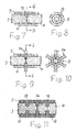
- Fig. 1 schematically a junction between two cables 1 and 2 is described, the conductors 3 and 4 are located in a pipe section 5 made of metal. They are defined in the pipe section 5 by a plurality of locking screws 6 in a position in which their end faces in a plane 7 abut each other, which is perpendicular to the axis of the cables 1 and 2 and the pipe section 5.
- Fig. 1 only four locking screws 6 located. In a practical embodiment are distributed over the entire length of the pipe section 5 and over its circumference locking screws 6, which are designed with advantage as shear screws.
- the pipe section 5 consists for example of an aluminum alloy.
- the two cables 1 and 2 have a conductor designed as a Milliken conductor.
- a conductor is for example in Fig. 2 shown and referred to as the conductor 3 of the cable 1.
- Head 4 of the cable 2 can be made identical.
- the conductor 3 consists of a plurality of wires stranded together of electrically good conductive material, such as copper or a copper alloy.
- the conductor 3 is according to Fig. 2 for example, divided into three sectoral ladder 8, 9 and 10, each extending over an angle of 120 ° and together form the circular conductor 3.
- the conductor 3 may also have more than three sector conductors. For example, six sectoral ladders are used in conventional technology.
- a layer 11 of insulating material is attached in each case.
- the conductor 3 is surrounded by a jacket 12 made of insulating material.
- In the three sector leaders 8, 9 and 10 are in Fig. 2 only a few wires drawn in each case.
- the pipe section 5 has in addition to threaded through holes for receiving the locking screws 6 about in its center at the level of level 7 also provided with a threaded, central through holes 13, of which in the plane 7 more circumferentially distributed in the pipe section 5 are attached. They serve to accommodate from the FIGS. 9 and 10 apparent contact screws 14, which are also designed with advantage as shear screws.
- the contact screws 14 serve the electrically conductive connection of the two conductors 3 and 4. They consist - as already mentioned - with advantage of copper or a copper alloy or of an aluminum alloy.
- the conductors 3 and 4 of the two cables 1 and 2 are inserted from two opposite sides in the pipe section 5 until they accordingly Fig. 3 lie in the plane 7 with their front sides together. In this position, the conductors 3 and 4 are determined by tightening the locking screws 6 in the pipe section 5. The conductors 3 and 4 are freed from the jacket 12 only on a length required for insertion into the pipe section 5. Further measures will not be carried out on ladders 3 and 4. This is especially true for all existing in the same insulating materials.
- drill sleeves 16 are advantageously screwed into the central through-holes 13, through which a drill 17 can be guided.
- the drill 17 has a smaller diameter than the central through holes 13 because of the drill holes 16 screwed into the central through holes 13, so that the holes 15 have a smaller diameter than the central through holes 13.
- the holes 15 should also have a smaller diameter than the through holes 13, if no drilling sleeves are used during drilling.
Landscapes
- Engineering & Computer Science (AREA)
- Manufacturing & Machinery (AREA)
- Connections Effected By Soldering, Adhesion, Or Permanent Deformation (AREA)
- Cable Accessories (AREA)
- Connections By Means Of Piercing Elements, Nuts, Or Screws (AREA)
Claims (2)
- Procédé pour la connexion électriquement conductrice des conducteurs électriques de deux câbles haute tension qui présentent à chaque fois un conducteur réalisé sous forme de conducteur de type Milliken entouré par une gaine en matériau isolant, dans lequel une pièce tubulaire (5) en métal est utilisée, laquelle présente, répartie sur toute sa longueur et sur sa périphérie, une pluralité de trous traversants pourvus d'un filetage, pour recevoir des vis de fixation (6), ainsi qu'approximativement en son milieu, dans un plan (7) s'étendant perpendiculairement à son axe, plusieurs trous traversants centraux (13) pourvus d'un filetage, décalés les uns par rapport aux autres dans la direction périphérique, pour recevoir des vis de contact (14), les conducteurs (3, 4) des deux câbles (1,2) étant d'abord dénudés à leurs extrémités en enlevant la gaine respective (12), caractérisé en ce- que les deux conducteurs (3, 4) sont ensuite enfichés depuis des côtés différents dans la pièce tubulaire (5) de telle sorte qu'ils s'appliquent l'un contre l'autre à la hauteur des trous traversants centraux (13) avec leurs côtés frontaux s'étendant perpendiculairement à leur axe,- que les conducteurs (3, 4) sont ensuite fixés au moyen des vis de fixation (6) dans la pièce tubulaire (5),- que des alésages (15) s'étendant dans la direction radiale à travers les trous traversants centraux (13) sont ensuite produits, lesquels pénètrent dans les deux conducteurs (3, 4) des deux câbles (1, 2) dans la région de leurs côtés frontaux et sont réalisés avec un diamètre inférieur par rapport au diamètre des trous traversants centraux (13), et- que des vis de contact (14) en métal bon conducteur électrique sont ensuite vissées dans les trous traversants centraux (13) et ensuite dans les alésages (15), ces vis, lors de leur montage, mordant avec leur filetage dans les deux conducteurs (3, 4).
- Procédé selon la revendication 1, caractérisé en ce que des trous traversants supplémentaires pourvus d'un filetage sont pratiqués dans l'étendue de la pièce tubulaire (5), à travers lesquels des vis de contact supplémentaires (18) s'engageant dans les deux conducteurs (3, 4) sont vissées.
Priority Applications (5)
| Application Number | Priority Date | Filing Date | Title |
|---|---|---|---|
| EP20120305789 EP2683034B1 (fr) | 2012-07-02 | 2012-07-02 | Procédé de connexion conductrice d'électricité du conducteur électrique de deux câbles de haute tension |
| US13/923,564 US9887508B2 (en) | 2012-07-02 | 2013-06-21 | Method for electrically conductively connecting the electrical conductors of two high voltage cables |
| AU2013206544A AU2013206544B2 (en) | 2012-07-02 | 2013-06-26 | Method for Electrically Conductively Connecting the Electrical Conductors of Two High Voltage Cables |
| BRBR102013016744-4A BR102013016744A2 (pt) | 2012-07-02 | 2013-06-28 | Método para conexão condutora de eletricidade de condutores elétricos de dois cabos de alta-tensão |
| CN201310388257.4A CN103579784B (zh) | 2012-07-02 | 2013-07-02 | 用于导电连接两条高压电缆的电导线的方法 |
Applications Claiming Priority (1)
| Application Number | Priority Date | Filing Date | Title |
|---|---|---|---|
| EP20120305789 EP2683034B1 (fr) | 2012-07-02 | 2012-07-02 | Procédé de connexion conductrice d'électricité du conducteur électrique de deux câbles de haute tension |
Publications (2)
| Publication Number | Publication Date |
|---|---|
| EP2683034A1 EP2683034A1 (fr) | 2014-01-08 |
| EP2683034B1 true EP2683034B1 (fr) | 2015-05-06 |
Family
ID=46598439
Family Applications (1)
| Application Number | Title | Priority Date | Filing Date |
|---|---|---|---|
| EP20120305789 Active EP2683034B1 (fr) | 2012-07-02 | 2012-07-02 | Procédé de connexion conductrice d'électricité du conducteur électrique de deux câbles de haute tension |
Country Status (5)
| Country | Link |
|---|---|
| US (1) | US9887508B2 (fr) |
| EP (1) | EP2683034B1 (fr) |
| CN (1) | CN103579784B (fr) |
| AU (1) | AU2013206544B2 (fr) |
| BR (1) | BR102013016744A2 (fr) |
Families Citing this family (13)
| Publication number | Priority date | Publication date | Assignee | Title |
|---|---|---|---|---|
| US9147967B2 (en) * | 2012-09-11 | 2015-09-29 | Tyco Electronics Canada Ulc | Electrical connectors and methods for using same |
| DE102014008756A1 (de) | 2014-06-12 | 2015-12-17 | Pfisterer Kontaktsysteme Gmbh | Vorrichtung zum Kontaktieren eines elektrischen Leiters sowie Anschluss- oder Verbindungseinrichtung mit einer solchen Vorrichtung |
| EP3001523B1 (fr) * | 2014-09-24 | 2018-11-14 | Tyco Electronics Raychem GmbH | Connecteur électrique pour connexion de bout en bout |
| ES2744334T3 (es) * | 2014-10-01 | 2020-02-24 | Brugg Ag Kabelwerke | Empalme de alta tensión |
| CN104876124B (zh) * | 2015-04-23 | 2017-08-08 | 山东莱钢建设有限公司 | 一种接续滑线导轨的方法、接续型滑线导轨 |
| DE102015005993B3 (de) * | 2015-05-08 | 2016-05-25 | Nkt Cables Gmbh & Co. Kg | Verfahren zum Verbinden von Hochspannungskabeln mit mehrdrähtigen Leitern |
| EP3507865A1 (fr) * | 2016-09-05 | 2019-07-10 | Relibond APS | Procédé de réalisation d'une interface électriquement conductrice de transmission de puissance, dispositif de formation d'interface et utilisation d'un appareil de pulvérisation à froid pour la formation d'une interface de transmission de puissance |
| CN106329457A (zh) * | 2016-10-13 | 2017-01-11 | 成都尚智恒达科技有限公司 | 一种电缆用接线固定设备 |
| NO343038B1 (no) * | 2016-12-27 | 2018-10-08 | Lyse Elnett As | Sikringsanordning for strømkabelende |
| JP7336807B2 (ja) | 2018-03-07 | 2023-09-01 | リライボンド アーペーエス | 電力ケーブル端部処理装置 |
| CN108614679A (zh) * | 2018-05-08 | 2018-10-02 | 南京航空航天大学 | 一种用于密立根油滴实验的数据处理方法 |
| EP4167384A1 (fr) * | 2021-10-14 | 2023-04-19 | TE Connectivity Solutions GmbH | Connecteurs de câble et systèmes et procédés de connecteurs de câble les comprenant |
| KR102543940B1 (ko) * | 2022-08-03 | 2023-06-14 | 나상원 | 부싱용 클램프단자 |
Family Cites Families (24)
| Publication number | Priority date | Publication date | Assignee | Title |
|---|---|---|---|---|
| US2392438A (en) * | 1940-05-02 | 1946-01-08 | Charles E Wade | Electrical connector |
| US3499100A (en) * | 1968-10-03 | 1970-03-03 | Anaconda Wire & Cable Co | Electric cable connectors |
| USRE28877E (en) * | 1971-02-19 | 1976-06-22 | Electric cable connector | |
| IT950146B (it) * | 1972-03-14 | 1973-06-20 | Pirelli | Perfezionamento nella costruzione di accessori per cavi elettrici ad alta tensione |
| US3996081A (en) * | 1974-09-26 | 1976-12-07 | General Electric Company | Method for making a high voltage cable splice |
| IT1112632B (it) * | 1978-05-30 | 1986-01-20 | Pirelli | Giunto perfezionato per cavi di basse e media tensione |
| IT1175762B (it) * | 1984-09-28 | 1987-07-15 | Pirelli Cavi Spa | Giunto per cavi ad isolante estruso |
| DE4036169A1 (de) * | 1990-05-11 | 1991-11-14 | Felten & Guilleaume Energie | Elektrischer leiter vom millikentyp mit verringerten wirbelstromverlusten |
| US5137476A (en) * | 1991-05-09 | 1992-08-11 | Noble John R | Electrical connectors |
| GB9414038D0 (en) * | 1994-07-11 | 1994-08-31 | Raychem Ltd | Electrical interconnection |
| US5630735A (en) * | 1995-07-07 | 1997-05-20 | Eckert; John C. | Electrical connector |
| US5957733A (en) * | 1997-06-25 | 1999-09-28 | Framatome Connectors Usa, Inc. | Electrical terminal connector |
| US6050844A (en) * | 1998-04-22 | 2000-04-18 | Johnson; Dee Lynn | Electrical connector with channels for wires |
| US6280264B1 (en) * | 2000-12-28 | 2001-08-28 | Eaton Corporation | Terminal connector securing wire with a wide range of diameters to a conductor of an electric power switch and an electric power switch incorporating the terminal connector |
| US6529112B1 (en) * | 2001-06-13 | 2003-03-04 | Siemens Energy & Automation, Inc. | Ring tongue lug retainer molded case circuit breaker |
| KR100481172B1 (ko) * | 2002-07-04 | 2005-04-07 | 삼성전자주식회사 | 고용량 터미널 연결고정장치 |
| FR2844101B1 (fr) * | 2002-08-30 | 2004-10-22 | Nexans | Connecteur de deux cables d'energie electrique et connexion comportant un tel connecteur |
| US6914191B2 (en) * | 2002-12-24 | 2005-07-05 | Secure Connect, Llc | Electrical connector for unstripped insulated wire |
| ATE554522T1 (de) * | 2008-02-13 | 2012-05-15 | Nexans | Vorrichtung für eine verbindungsstelle zwischen zwei elektrischen hochspannungskabeln mit unterschiedlichen durchmessern |
| EP2148392A1 (fr) * | 2008-07-25 | 2010-01-27 | Nexans | Vis de serrage |
| US7537467B1 (en) * | 2008-10-07 | 2009-05-26 | Arlington Industries, Inc. | Grounding terminal block assembly for multiple services |
| EP2226899B1 (fr) * | 2009-02-25 | 2011-05-18 | Nexans | Dispositif de liaison de deux conducteurs électriques |
| CA2819928C (fr) * | 2010-12-22 | 2018-01-23 | Prysmian S.P.A. | Procede pour fabriquer un element de jonction pour cables electriques a moyenne ou haute tension et ensemble de jonction pouvant etre obtenu par ledit procede |
| US8602829B2 (en) * | 2012-03-23 | 2013-12-10 | Schneider Electric USA, Inc. | Cable connector with integrated shoe |
-
2012
- 2012-07-02 EP EP20120305789 patent/EP2683034B1/fr active Active
-
2013
- 2013-06-21 US US13/923,564 patent/US9887508B2/en active Active
- 2013-06-26 AU AU2013206544A patent/AU2013206544B2/en not_active Ceased
- 2013-06-28 BR BRBR102013016744-4A patent/BR102013016744A2/pt not_active Application Discontinuation
- 2013-07-02 CN CN201310388257.4A patent/CN103579784B/zh not_active Expired - Fee Related
Also Published As
| Publication number | Publication date |
|---|---|
| BR102013016744A2 (pt) | 2015-07-14 |
| AU2013206544A1 (en) | 2014-01-16 |
| AU2013206544B2 (en) | 2016-11-24 |
| CN103579784B (zh) | 2017-06-06 |
| US20140000110A1 (en) | 2014-01-02 |
| CN103579784A (zh) | 2014-02-12 |
| US9887508B2 (en) | 2018-02-06 |
| EP2683034A1 (fr) | 2014-01-08 |
Similar Documents
| Publication | Publication Date | Title |
|---|---|---|
| EP2683034B1 (fr) | Procédé de connexion conductrice d'électricité du conducteur électrique de deux câbles de haute tension | |
| EP2202758B1 (fr) | Câble pour la mise à terre des équipments dans les chemins de fer | |
| EP2226899B1 (fr) | Dispositif de liaison de deux conducteurs électriques | |
| EP2856566B1 (fr) | Système de raccordement électrique | |
| DE10354284A1 (de) | Abgeschirmter Kabelbaum | |
| DE112008000565T5 (de) | Abschirmschale | |
| DE112014002495T5 (de) | Verbindungsstruktur für Metallklemmenanschlussstücke | |
| DE112013002527T5 (de) | Elektrokabel-Schutzrohr und Kabelstrang | |
| EP2360804A1 (fr) | Agencement destiné à connecter deux câbles d'énergie | |
| DE102013021278B3 (de) | Verfahren zum elektrisch leitenden Verbinden einer Leitung mit einem Kontaktelement | |
| EP2874236B1 (fr) | Dispositif de contact pour la mise en contact d'un blindage de câble | |
| EP3262724B1 (fr) | Faisceau de câbles haute tension | |
| EP3091619B1 (fr) | Procede de raccordement de cables haute tension par des conducteurs multibrins | |
| DE102011077886B4 (de) | Verfahren zur Leitungskonfektionierung | |
| EP2940803B1 (fr) | Connection électrique pour des câbles de courant | |
| EP3121903A1 (fr) | Systeme dote d'un connecteur pour au moins un cable electrique | |
| EP3490074B1 (fr) | Agencement permettant de mettre en contact un blindage d'un câble | |
| WO2019038223A1 (fr) | Pale de rotor d'éolienne et système paratonnerre pour une pale de rotor d'éolienne | |
| EP3496208B1 (fr) | Dispositif de contact et système de contact pour câble coaxial haute tension | |
| EP3627626B1 (fr) | Élement de contact | |
| CH707159B1 (de) | Elektrisches Verbindungselement. | |
| DE2456430A1 (de) | Loetfreie verbindungsbaugruppe | |
| EP3638546B1 (fr) | Ensemble de faisceaux de câbles, véhicule ferroviaire et procédé de fabrication de l'ensemble | |
| DE202016105389U1 (de) | Außenleiterkontakt für koaxiales Kabel | |
| DE102005022190B3 (de) | Energie-Bus-Kabel |
Legal Events
| Date | Code | Title | Description |
|---|---|---|---|
| PUAI | Public reference made under article 153(3) epc to a published international application that has entered the european phase |
Free format text: ORIGINAL CODE: 0009012 |
|
| 17P | Request for examination filed |
Effective date: 20130610 |
|
| AK | Designated contracting states |
Kind code of ref document: A1 Designated state(s): AL AT BE BG CH CY CZ DE DK EE ES FI FR GB GR HR HU IE IS IT LI LT LU LV MC MK MT NL NO PL PT RO RS SE SI SK SM TR |
|
| AX | Request for extension of the european patent |
Extension state: BA ME |
|
| REG | Reference to a national code |
Ref country code: DE Ref legal event code: R079 Ref document number: 502012003046 Country of ref document: DE Free format text: PREVIOUS MAIN CLASS: H01R0004360000 Ipc: H01R0043000000 |
|
| GRAP | Despatch of communication of intention to grant a patent |
Free format text: ORIGINAL CODE: EPIDOSNIGR1 |
|
| RIC1 | Information provided on ipc code assigned before grant |
Ipc: H02G 15/08 20060101ALI20141106BHEP Ipc: H01R 43/00 20060101AFI20141106BHEP Ipc: H01R 4/30 20060101ALI20141106BHEP Ipc: H01R 4/36 20060101ALI20141106BHEP |
|
| INTG | Intention to grant announced |
Effective date: 20141125 |
|
| GRAS | Grant fee paid |
Free format text: ORIGINAL CODE: EPIDOSNIGR3 |
|
| GRAA | (expected) grant |
Free format text: ORIGINAL CODE: 0009210 |
|
| AK | Designated contracting states |
Kind code of ref document: B1 Designated state(s): AL AT BE BG CH CY CZ DE DK EE ES FI FR GB GR HR HU IE IS IT LI LT LU LV MC MK MT NL NO PL PT RO RS SE SI SK SM TR |
|
| REG | Reference to a national code |
Ref country code: GB Ref legal event code: FG4D Free format text: NOT ENGLISH |
|
| REG | Reference to a national code |
Ref country code: CH Ref legal event code: EP |
|
| REG | Reference to a national code |
Ref country code: IE Ref legal event code: FG4D Free format text: LANGUAGE OF EP DOCUMENT: GERMAN |
|
| REG | Reference to a national code |
Ref country code: DE Ref legal event code: R096 Ref document number: 502012003046 Country of ref document: DE Effective date: 20150611 |
|
| REG | Reference to a national code |
Ref country code: AT Ref legal event code: REF Ref document number: 726268 Country of ref document: AT Kind code of ref document: T Effective date: 20150615 |
|
| REG | Reference to a national code |
Ref country code: SE Ref legal event code: TRGR |
|
| REG | Reference to a national code |
Ref country code: FR Ref legal event code: PLFP Year of fee payment: 4 |
|
| REG | Reference to a national code |
Ref country code: NL Ref legal event code: MP Effective date: 20150506 |
|
| REG | Reference to a national code |
Ref country code: LT Ref legal event code: MG4D |
|
| PG25 | Lapsed in a contracting state [announced via postgrant information from national office to epo] |
Ref country code: NO Free format text: LAPSE BECAUSE OF FAILURE TO SUBMIT A TRANSLATION OF THE DESCRIPTION OR TO PAY THE FEE WITHIN THE PRESCRIBED TIME-LIMIT Effective date: 20150806 Ref country code: FI Free format text: LAPSE BECAUSE OF FAILURE TO SUBMIT A TRANSLATION OF THE DESCRIPTION OR TO PAY THE FEE WITHIN THE PRESCRIBED TIME-LIMIT Effective date: 20150506 Ref country code: ES Free format text: LAPSE BECAUSE OF FAILURE TO SUBMIT A TRANSLATION OF THE DESCRIPTION OR TO PAY THE FEE WITHIN THE PRESCRIBED TIME-LIMIT Effective date: 20150506 Ref country code: LT Free format text: LAPSE BECAUSE OF FAILURE TO SUBMIT A TRANSLATION OF THE DESCRIPTION OR TO PAY THE FEE WITHIN THE PRESCRIBED TIME-LIMIT Effective date: 20150506 Ref country code: HR Free format text: LAPSE BECAUSE OF FAILURE TO SUBMIT A TRANSLATION OF THE DESCRIPTION OR TO PAY THE FEE WITHIN THE PRESCRIBED TIME-LIMIT Effective date: 20150506 Ref country code: PT Free format text: LAPSE BECAUSE OF FAILURE TO SUBMIT A TRANSLATION OF THE DESCRIPTION OR TO PAY THE FEE WITHIN THE PRESCRIBED TIME-LIMIT Effective date: 20150907 |
|
| PG25 | Lapsed in a contracting state [announced via postgrant information from national office to epo] |
Ref country code: GR Free format text: LAPSE BECAUSE OF FAILURE TO SUBMIT A TRANSLATION OF THE DESCRIPTION OR TO PAY THE FEE WITHIN THE PRESCRIBED TIME-LIMIT Effective date: 20150807 Ref country code: BG Free format text: LAPSE BECAUSE OF FAILURE TO SUBMIT A TRANSLATION OF THE DESCRIPTION OR TO PAY THE FEE WITHIN THE PRESCRIBED TIME-LIMIT Effective date: 20150806 Ref country code: RS Free format text: LAPSE BECAUSE OF FAILURE TO SUBMIT A TRANSLATION OF THE DESCRIPTION OR TO PAY THE FEE WITHIN THE PRESCRIBED TIME-LIMIT Effective date: 20150506 Ref country code: LV Free format text: LAPSE BECAUSE OF FAILURE TO SUBMIT A TRANSLATION OF THE DESCRIPTION OR TO PAY THE FEE WITHIN THE PRESCRIBED TIME-LIMIT Effective date: 20150506 Ref country code: IS Free format text: LAPSE BECAUSE OF FAILURE TO SUBMIT A TRANSLATION OF THE DESCRIPTION OR TO PAY THE FEE WITHIN THE PRESCRIBED TIME-LIMIT Effective date: 20150906 |
|
| PG25 | Lapsed in a contracting state [announced via postgrant information from national office to epo] |
Ref country code: DK Free format text: LAPSE BECAUSE OF FAILURE TO SUBMIT A TRANSLATION OF THE DESCRIPTION OR TO PAY THE FEE WITHIN THE PRESCRIBED TIME-LIMIT Effective date: 20150506 Ref country code: EE Free format text: LAPSE BECAUSE OF FAILURE TO SUBMIT A TRANSLATION OF THE DESCRIPTION OR TO PAY THE FEE WITHIN THE PRESCRIBED TIME-LIMIT Effective date: 20150506 |
|
| REG | Reference to a national code |
Ref country code: DE Ref legal event code: R097 Ref document number: 502012003046 Country of ref document: DE |
|
| PG25 | Lapsed in a contracting state [announced via postgrant information from national office to epo] |
Ref country code: MC Free format text: LAPSE BECAUSE OF FAILURE TO SUBMIT A TRANSLATION OF THE DESCRIPTION OR TO PAY THE FEE WITHIN THE PRESCRIBED TIME-LIMIT Effective date: 20150506 Ref country code: PL Free format text: LAPSE BECAUSE OF FAILURE TO SUBMIT A TRANSLATION OF THE DESCRIPTION OR TO PAY THE FEE WITHIN THE PRESCRIBED TIME-LIMIT Effective date: 20150506 Ref country code: CZ Free format text: LAPSE BECAUSE OF FAILURE TO SUBMIT A TRANSLATION OF THE DESCRIPTION OR TO PAY THE FEE WITHIN THE PRESCRIBED TIME-LIMIT Effective date: 20150506 Ref country code: SK Free format text: LAPSE BECAUSE OF FAILURE TO SUBMIT A TRANSLATION OF THE DESCRIPTION OR TO PAY THE FEE WITHIN THE PRESCRIBED TIME-LIMIT Effective date: 20150506 Ref country code: RO Free format text: LAPSE BECAUSE OF NON-PAYMENT OF DUE FEES Effective date: 20150506 |
|
| PLBE | No opposition filed within time limit |
Free format text: ORIGINAL CODE: 0009261 |
|
| STAA | Information on the status of an ep patent application or granted ep patent |
Free format text: STATUS: NO OPPOSITION FILED WITHIN TIME LIMIT |
|
| PG25 | Lapsed in a contracting state [announced via postgrant information from national office to epo] |
Ref country code: LU Free format text: LAPSE BECAUSE OF FAILURE TO SUBMIT A TRANSLATION OF THE DESCRIPTION OR TO PAY THE FEE WITHIN THE PRESCRIBED TIME-LIMIT Effective date: 20150702 |
|
| 26N | No opposition filed |
Effective date: 20160209 |
|
| REG | Reference to a national code |
Ref country code: IE Ref legal event code: MM4A |
|
| PG25 | Lapsed in a contracting state [announced via postgrant information from national office to epo] |
Ref country code: SI Free format text: LAPSE BECAUSE OF FAILURE TO SUBMIT A TRANSLATION OF THE DESCRIPTION OR TO PAY THE FEE WITHIN THE PRESCRIBED TIME-LIMIT Effective date: 20150506 |
|
| REG | Reference to a national code |
Ref country code: FR Ref legal event code: PLFP Year of fee payment: 5 |
|
| PG25 | Lapsed in a contracting state [announced via postgrant information from national office to epo] |
Ref country code: IE Free format text: LAPSE BECAUSE OF NON-PAYMENT OF DUE FEES Effective date: 20150702 |
|
| GBPC | Gb: european patent ceased through non-payment of renewal fee |
Effective date: 20160702 |
|
| PG25 | Lapsed in a contracting state [announced via postgrant information from national office to epo] |
Ref country code: MT Free format text: LAPSE BECAUSE OF FAILURE TO SUBMIT A TRANSLATION OF THE DESCRIPTION OR TO PAY THE FEE WITHIN THE PRESCRIBED TIME-LIMIT Effective date: 20150506 |
|
| PG25 | Lapsed in a contracting state [announced via postgrant information from national office to epo] |
Ref country code: SM Free format text: LAPSE BECAUSE OF FAILURE TO SUBMIT A TRANSLATION OF THE DESCRIPTION OR TO PAY THE FEE WITHIN THE PRESCRIBED TIME-LIMIT Effective date: 20150506 Ref country code: HU Free format text: LAPSE BECAUSE OF FAILURE TO SUBMIT A TRANSLATION OF THE DESCRIPTION OR TO PAY THE FEE WITHIN THE PRESCRIBED TIME-LIMIT; INVALID AB INITIO Effective date: 20120702 Ref country code: GB Free format text: LAPSE BECAUSE OF NON-PAYMENT OF DUE FEES Effective date: 20160702 |
|
| PG25 | Lapsed in a contracting state [announced via postgrant information from national office to epo] |
Ref country code: CY Free format text: LAPSE BECAUSE OF FAILURE TO SUBMIT A TRANSLATION OF THE DESCRIPTION OR TO PAY THE FEE WITHIN THE PRESCRIBED TIME-LIMIT Effective date: 20150506 Ref country code: NL Free format text: LAPSE BECAUSE OF FAILURE TO SUBMIT A TRANSLATION OF THE DESCRIPTION OR TO PAY THE FEE WITHIN THE PRESCRIBED TIME-LIMIT Effective date: 20150506 |
|
| REG | Reference to a national code |
Ref country code: FR Ref legal event code: PLFP Year of fee payment: 6 |
|
| PG25 | Lapsed in a contracting state [announced via postgrant information from national office to epo] |
Ref country code: BE Free format text: LAPSE BECAUSE OF NON-PAYMENT OF DUE FEES Effective date: 20150731 |
|
| PG25 | Lapsed in a contracting state [announced via postgrant information from national office to epo] |
Ref country code: MK Free format text: LAPSE BECAUSE OF FAILURE TO SUBMIT A TRANSLATION OF THE DESCRIPTION OR TO PAY THE FEE WITHIN THE PRESCRIBED TIME-LIMIT Effective date: 20150506 Ref country code: TR Free format text: LAPSE BECAUSE OF FAILURE TO SUBMIT A TRANSLATION OF THE DESCRIPTION OR TO PAY THE FEE WITHIN THE PRESCRIBED TIME-LIMIT Effective date: 20150506 |
|
| REG | Reference to a national code |
Ref country code: FR Ref legal event code: PLFP Year of fee payment: 7 |
|
| REG | Reference to a national code |
Ref country code: AT Ref legal event code: MM01 Ref document number: 726268 Country of ref document: AT Kind code of ref document: T Effective date: 20170702 |
|
| PG25 | Lapsed in a contracting state [announced via postgrant information from national office to epo] |
Ref country code: AL Free format text: LAPSE BECAUSE OF FAILURE TO SUBMIT A TRANSLATION OF THE DESCRIPTION OR TO PAY THE FEE WITHIN THE PRESCRIBED TIME-LIMIT Effective date: 20150506 |
|
| PG25 | Lapsed in a contracting state [announced via postgrant information from national office to epo] |
Ref country code: AT Free format text: LAPSE BECAUSE OF NON-PAYMENT OF DUE FEES Effective date: 20170702 |
|
| PGFP | Annual fee paid to national office [announced via postgrant information from national office to epo] |
Ref country code: IT Payment date: 20230724 Year of fee payment: 12 Ref country code: CH Payment date: 20230801 Year of fee payment: 12 |
|
| PGFP | Annual fee paid to national office [announced via postgrant information from national office to epo] |
Ref country code: SE Payment date: 20230719 Year of fee payment: 12 Ref country code: FR Payment date: 20230725 Year of fee payment: 12 Ref country code: DE Payment date: 20230719 Year of fee payment: 12 |