EP2683034B1 - Method for a connection conducting electricity between the electricity conductors of two electrical units - Google Patents
Method for a connection conducting electricity between the electricity conductors of two electrical units Download PDFInfo
- Publication number
- EP2683034B1 EP2683034B1 EP20120305789 EP12305789A EP2683034B1 EP 2683034 B1 EP2683034 B1 EP 2683034B1 EP 20120305789 EP20120305789 EP 20120305789 EP 12305789 A EP12305789 A EP 12305789A EP 2683034 B1 EP2683034 B1 EP 2683034B1
- Authority
- EP
- European Patent Office
- Prior art keywords
- conductors
- throughholes
- pipe piece
- central
- screws
- Prior art date
- Legal status (The legal status is an assumption and is not a legal conclusion. Google has not performed a legal analysis and makes no representation as to the accuracy of the status listed.)
- Active
Links
- 239000004020 conductor Substances 0.000 title claims description 60
- 238000000034 method Methods 0.000 title claims description 10
- 230000005611 electricity Effects 0.000 title 2
- 239000011810 insulating material Substances 0.000 claims description 5
- 229910052751 metal Inorganic materials 0.000 claims description 4
- 239000002184 metal Substances 0.000 claims description 4
- 229910000838 Al alloy Inorganic materials 0.000 description 3
- RYGMFSIKBFXOCR-UHFFFAOYSA-N Copper Chemical compound [Cu] RYGMFSIKBFXOCR-UHFFFAOYSA-N 0.000 description 3
- 229910000881 Cu alloy Inorganic materials 0.000 description 3
- 229910052802 copper Inorganic materials 0.000 description 3
- 239000010949 copper Substances 0.000 description 3
- 230000000694 effects Effects 0.000 description 3
- 238000005553 drilling Methods 0.000 description 2
- 238000009413 insulation Methods 0.000 description 2
- 239000004922 lacquer Substances 0.000 description 2
- FGRBYDKOBBBPOI-UHFFFAOYSA-N 10,10-dioxo-2-[4-(N-phenylanilino)phenyl]thioxanthen-9-one Chemical compound O=C1c2ccccc2S(=O)(=O)c2ccc(cc12)-c1ccc(cc1)N(c1ccccc1)c1ccccc1 FGRBYDKOBBBPOI-UHFFFAOYSA-N 0.000 description 1
- 238000007792 addition Methods 0.000 description 1
- 230000002500 effect on skin Effects 0.000 description 1
- 238000005516 engineering process Methods 0.000 description 1
- 238000003780 insertion Methods 0.000 description 1
- 230000037431 insertion Effects 0.000 description 1
- 239000000463 material Substances 0.000 description 1
- 239000003973 paint Substances 0.000 description 1
Images

Classifications
-
- H—ELECTRICITY
- H01—ELECTRIC ELEMENTS
- H01R—ELECTRICALLY-CONDUCTIVE CONNECTIONS; STRUCTURAL ASSOCIATIONS OF A PLURALITY OF MUTUALLY-INSULATED ELECTRICAL CONNECTING ELEMENTS; COUPLING DEVICES; CURRENT COLLECTORS
- H01R4/00—Electrically-conductive connections between two or more conductive members in direct contact, i.e. touching one another; Means for effecting or maintaining such contact; Electrically-conductive connections having two or more spaced connecting locations for conductors and using contact members penetrating insulation
- H01R4/28—Clamped connections, spring connections
- H01R4/30—Clamped connections, spring connections utilising a screw or nut clamping member
- H01R4/305—Clamped connections, spring connections utilising a screw or nut clamping member having means for facilitating engagement of conductive member or for holding it in position
-
- H—ELECTRICITY
- H01—ELECTRIC ELEMENTS
- H01R—ELECTRICALLY-CONDUCTIVE CONNECTIONS; STRUCTURAL ASSOCIATIONS OF A PLURALITY OF MUTUALLY-INSULATED ELECTRICAL CONNECTING ELEMENTS; COUPLING DEVICES; CURRENT COLLECTORS
- H01R43/00—Apparatus or processes specially adapted for manufacturing, assembling, maintaining, or repairing of line connectors or current collectors or for joining electric conductors
-
- H—ELECTRICITY
- H01—ELECTRIC ELEMENTS
- H01R—ELECTRICALLY-CONDUCTIVE CONNECTIONS; STRUCTURAL ASSOCIATIONS OF A PLURALITY OF MUTUALLY-INSULATED ELECTRICAL CONNECTING ELEMENTS; COUPLING DEVICES; CURRENT COLLECTORS
- H01R11/00—Individual connecting elements providing two or more spaced connecting locations for conductive members which are, or may be, thereby interconnected, e.g. end pieces for wires or cables supported by the wire or cable and having means for facilitating electrical connection to some other wire, terminal, or conductive member, blocks of binding posts
- H01R11/01—Individual connecting elements providing two or more spaced connecting locations for conductive members which are, or may be, thereby interconnected, e.g. end pieces for wires or cables supported by the wire or cable and having means for facilitating electrical connection to some other wire, terminal, or conductive member, blocks of binding posts characterised by the form or arrangement of the conductive interconnection between the connecting locations
-
- H—ELECTRICITY
- H01—ELECTRIC ELEMENTS
- H01R—ELECTRICALLY-CONDUCTIVE CONNECTIONS; STRUCTURAL ASSOCIATIONS OF A PLURALITY OF MUTUALLY-INSULATED ELECTRICAL CONNECTING ELEMENTS; COUPLING DEVICES; CURRENT COLLECTORS
- H01R4/00—Electrically-conductive connections between two or more conductive members in direct contact, i.e. touching one another; Means for effecting or maintaining such contact; Electrically-conductive connections having two or more spaced connecting locations for conductors and using contact members penetrating insulation
- H01R4/28—Clamped connections, spring connections
- H01R4/30—Clamped connections, spring connections utilising a screw or nut clamping member
- H01R4/36—Conductive members located under tip of screw
-
- H—ELECTRICITY
- H02—GENERATION; CONVERSION OR DISTRIBUTION OF ELECTRIC POWER
- H02G—INSTALLATION OF ELECTRIC CABLES OR LINES, OR OF COMBINED OPTICAL AND ELECTRIC CABLES OR LINES
- H02G15/00—Cable fittings
- H02G15/08—Cable junctions
-
- H—ELECTRICITY
- H01—ELECTRIC ELEMENTS
- H01R—ELECTRICALLY-CONDUCTIVE CONNECTIONS; STRUCTURAL ASSOCIATIONS OF A PLURALITY OF MUTUALLY-INSULATED ELECTRICAL CONNECTING ELEMENTS; COUPLING DEVICES; CURRENT COLLECTORS
- H01R4/00—Electrically-conductive connections between two or more conductive members in direct contact, i.e. touching one another; Means for effecting or maintaining such contact; Electrically-conductive connections having two or more spaced connecting locations for conductors and using contact members penetrating insulation
- H01R4/28—Clamped connections, spring connections
- H01R4/30—Clamped connections, spring connections utilising a screw or nut clamping member
- H01R4/308—Conductive members located parallel to axis of screw
-
- Y—GENERAL TAGGING OF NEW TECHNOLOGICAL DEVELOPMENTS; GENERAL TAGGING OF CROSS-SECTIONAL TECHNOLOGIES SPANNING OVER SEVERAL SECTIONS OF THE IPC; TECHNICAL SUBJECTS COVERED BY FORMER USPC CROSS-REFERENCE ART COLLECTIONS [XRACs] AND DIGESTS
- Y10—TECHNICAL SUBJECTS COVERED BY FORMER USPC
- Y10T—TECHNICAL SUBJECTS COVERED BY FORMER US CLASSIFICATION
- Y10T29/00—Metal working
- Y10T29/49—Method of mechanical manufacture
- Y10T29/49002—Electrical device making
- Y10T29/49117—Conductor or circuit manufacturing
- Y10T29/49194—Assembling elongated conductors, e.g., splicing, etc.
- Y10T29/49195—Assembling elongated conductors, e.g., splicing, etc. with end-to-end orienting
Definitions
- the invention relates to a method for electrically conductive connection of the electrical conductors of two high-voltage cables according to the preamble of patent claim 1.
- Such a method is for example from the EP 2 226 899 A1 out.
- Milliken conductors are usually used in single-phase high-voltage cables with large conductor cross-sections, which are for example over 1000 mm 2 . They consist of a plurality of electrically conductive wires, which are stranded together and combined in at least three sector conductors, which together form a circular conductor. Such a Millikenleiter with six sector leaders, for example, from the DE 40 36 169 C2 out. To reduce the skin effect on the one hand and the proximity effect on the other hand, the sector leaders are isolated from each other. To further reduce the effects of these two effects, the individual wires of the Milliken conductor can also be insulated from one another, for example by applying a lacquer layer to each individual wire.
- the invention has for its object to make the initially described method so that the two Millikenleiter can be connected electrically effective with reduced effort.
- contact screws have a relation to the inner diameter of the holes slightly larger diameter so that they cut with their thread in the two conductors.
- the electrically conductive connection between the conductors of the two cables is then completed. If necessary, a current to be transmitted by means of the cable flows directly from conductor to conductor via the contact screws.
- the contact screws advantageously consist of copper or a copper alloy or of an aluminum alloy.
- Fig. 1 schematically a junction between two cables 1 and 2 is described, the conductors 3 and 4 are located in a pipe section 5 made of metal. They are defined in the pipe section 5 by a plurality of locking screws 6 in a position in which their end faces in a plane 7 abut each other, which is perpendicular to the axis of the cables 1 and 2 and the pipe section 5.
- Fig. 1 only four locking screws 6 located. In a practical embodiment are distributed over the entire length of the pipe section 5 and over its circumference locking screws 6, which are designed with advantage as shear screws.
- the pipe section 5 consists for example of an aluminum alloy.
- the two cables 1 and 2 have a conductor designed as a Milliken conductor.
- a conductor is for example in Fig. 2 shown and referred to as the conductor 3 of the cable 1.
- Head 4 of the cable 2 can be made identical.
- the conductor 3 consists of a plurality of wires stranded together of electrically good conductive material, such as copper or a copper alloy.
- the conductor 3 is according to Fig. 2 for example, divided into three sectoral ladder 8, 9 and 10, each extending over an angle of 120 ° and together form the circular conductor 3.
- the conductor 3 may also have more than three sector conductors. For example, six sectoral ladders are used in conventional technology.
- a layer 11 of insulating material is attached in each case.
- the conductor 3 is surrounded by a jacket 12 made of insulating material.
- In the three sector leaders 8, 9 and 10 are in Fig. 2 only a few wires drawn in each case.
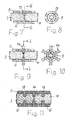
- the pipe section 5 has in addition to threaded through holes for receiving the locking screws 6 about in its center at the level of level 7 also provided with a threaded, central through holes 13, of which in the plane 7 more circumferentially distributed in the pipe section 5 are attached. They serve to accommodate from the FIGS. 9 and 10 apparent contact screws 14, which are also designed with advantage as shear screws.
- the contact screws 14 serve the electrically conductive connection of the two conductors 3 and 4. They consist - as already mentioned - with advantage of copper or a copper alloy or of an aluminum alloy.
- the conductors 3 and 4 of the two cables 1 and 2 are inserted from two opposite sides in the pipe section 5 until they accordingly Fig. 3 lie in the plane 7 with their front sides together. In this position, the conductors 3 and 4 are determined by tightening the locking screws 6 in the pipe section 5. The conductors 3 and 4 are freed from the jacket 12 only on a length required for insertion into the pipe section 5. Further measures will not be carried out on ladders 3 and 4. This is especially true for all existing in the same insulating materials.
- drill sleeves 16 are advantageously screwed into the central through-holes 13, through which a drill 17 can be guided.
- the drill 17 has a smaller diameter than the central through holes 13 because of the drill holes 16 screwed into the central through holes 13, so that the holes 15 have a smaller diameter than the central through holes 13.
- the holes 15 should also have a smaller diameter than the through holes 13, if no drilling sleeves are used during drilling.
Landscapes
- Engineering & Computer Science (AREA)
- Manufacturing & Machinery (AREA)
- Connections Effected By Soldering, Adhesion, Or Permanent Deformation (AREA)
- Cable Accessories (AREA)
- Connections By Means Of Piercing Elements, Nuts, Or Screws (AREA)
Description
Die Erfindung bezieht sich auf ein Verfahren zum elektrisch leitenden Verbinden der elektrischen Leiter von zwei Hochspannungskabeln gemäß dem Oberbegriff des Patentanspruchs 1.The invention relates to a method for electrically conductive connection of the electrical conductors of two high-voltage cables according to the preamble of patent claim 1.
Ein solches Verfahren geht beispielsweise aus der
Millikenleiter werden in der Regel bei Einleiter-Hochspannungskabeln mit großen Leiterquerschnitten eingesetzt, die beispielsweise bei über 1000 mm2 liegen. Sie bestehen aus einer Vielzahl von elektrisch leitenden Drähten, die miteinander verseilt und in mindestens drei Sektorleitern zusammengefaßt sind, welche gemeinsam einen kreisrunden Leiter bilden. Ein solcher Millikenleiter mit sechs Sektorleitern geht beispielsweise aus der
In der eingangs erwähnten
Der Erfindung liegt die Aufgabe zugrunde, das eingangs geschilderte Verfahren so zu gestalten, daß die beiden Millikenleiter mit vermindertem Aufwand elektrisch wirksam durchverbunden werden können.The invention has for its object to make the initially described method so that the two Millikenleiter can be connected electrically effective with reduced effort.
Diese Aufgabe wird entsprechend den kennzeichnenden Merkmalen des Patentanspruchs 1 gelöst.This object is achieved according to the characterizing features of claim 1.
Bei Einsatz dieses Verfahrens brauchen nur die beiden vom Mantel befreiten Leiter der zu verbindenden Kabel in das Rohrstück eingesteckt und in demselben mit aneinander liegenden Stirnseiten festgelegt zu werden. In den Leitern der beiden Kabel vorhandene Isoliermaterialien, wie die gegenseitige Isolierung der Sektorleiter und gegebenenfalls auf den einzelnen Drähten vorhandene Lackschichten, können in denselben verbleiben. Nach Festlegung der beiden Leiter in dem Rohrstück mittels der Feststellschrauben liegen dieselben mit ihren Stirnseiten unverrückbar aneinander. Es werden dann mittels eines durch die zentralen Durchgangslöcher hindurchgeführten Bohrers Bohrungen erzeugt, die radial in das Rohrstück hineinragen und so zwischen den beiden Leitern liegen, daß sie möglichst gleichmäßig in beide Leiter hineinragen. Die abschließend in die zentralen Durchgangslöcher und weiterführend in die Bohrungen einzuschraubenden Kontaktschrauben haben einen gegenüber dem Innendurchmesser der Bohrungen geringfügig größeren Durchmesser, so daß sie mit ihrem Gewinde in die beiden Leiter einschneiden. Die elektrisch leitende Verbindung zwischen den Leitern der beiden Kabel ist dann fertiggestellt. Ein mittels der Kabel zu übertragender Strom fließt gegebenenfalls über die Kontaktschrauben direkt von Leiter zu Leiter. Die Kontaktschrauben bestehen in Abhängigkeit vom Material der Leiter mit Vorteil aus Kupfer oder einer Kupferlegierung bzw. aus einer Aluminiumlegierung.When using this method, only the two freed from the jacket conductor of the cable to be connected need to be inserted into the pipe section and set in the same with adjacent end faces. Insulating materials present in the conductors of the two cables, such as the mutual insulation of the sector conductors and, if appropriate, paint layers present on the individual wires, can remain in them. After fixing the two conductors in the pipe section by means of the locking screws are the same with their front sides immovably together. Then, bores are produced by means of a drill passed through the central through holes, which project radially into the pipe section and lie between the two conductors in such a way that they project as evenly as possible into both conductors. The finally screwed into the central through holes and continue to be drilled in the holes contact screws have a relation to the inner diameter of the holes slightly larger diameter so that they cut with their thread in the two conductors. The electrically conductive connection between the conductors of the two cables is then completed. If necessary, a current to be transmitted by means of the cable flows directly from conductor to conductor via the contact screws. Depending on the material of the conductors, the contact screws advantageously consist of copper or a copper alloy or of an aluminum alloy.
Das Verfahren nach der Erfindung wird anhand der Zeichnungen als Ausführungsbeispiel erläutert.The method according to the invention will be explained with reference to the drawings as an exemplary embodiment.
Es zeigen:
-
Fig. 1 schematisch eine Verbindungsstelle zwischen zwei elektrischen Hochspannungskabeln mit Millikenleitern teilweise im Schnitt. -
Fig. 2 eine Ansicht der Stirnseite eines der Kabel nachFig. 1 . -
Fig. 3 eine gegenüberFig. 1 ergänzte Verbindungsstelle im Schnitt. -
Fig. 4 einen Schnitt durchFig. 3 entlang der Linie IV - IV. -
Fig. 5 und 6 Ergänzungen zur Verbindungsstelle nachFig. 3 . -
Fig. 7 einen Schnitt durch eine ergänzte Verbindungsstelle nachFig. 3 . -
Fig. 8 einen Schnitt durchFig. 7 entlang der Linie VIII - VIII. -
Fig. 9 eine gegenüberFig. 7 weiter ergänzte Verbindungsstelle. -
Fig. 10 einen Schnitt durchFig. 9 entlang der Linie X-X. -
Fig. 11 einen Schnitt durch eine gegenüberFig. 9 weiter ergänzte Verbindungsstelle.
-
Fig. 1 schematically a junction between two high voltage electrical cables with Millikenleitern partially in section. -
Fig. 2 a view of the front side of one of the cables behindFig. 1 , -
Fig. 3 one oppositeFig. 1 supplemented junction on average. -
Fig. 4 a cut throughFig. 3 along the line IV - IV. -
FIGS. 5 and 6 Additions to the connection point according toFig. 3 , -
Fig. 7 a section through a supplemented joint afterFig. 3 , -
Fig. 8 a cut throughFig. 7 along the line VIII - VIII. -
Fig. 9 one oppositeFig. 7 further supplemented connection point. -
Fig. 10 a cut throughFig. 9 along the line XX. -
Fig. 11 a cut through one oppositeFig. 9 further supplemented connection point.
In
Die beiden Kabel 1 und 2 haben einen als Millikenleiter ausgeführten Leiter. Ein solcher Leiter ist beispielsweise in
Das Rohrstück 5 hat neben mit einem Gewinde versehenen Durchgangslöchern zur Aufnahme der Feststellschrauben 6 etwa in seiner Mitte in Höhe der Ebene 7 ebenfalls mit einem Gewinde versehene, zentrale Durchgangslöcher 13, von denen in der Ebene 7 mehrere in Umfangsrichtung verteilt im Rohrstück 5 angebracht sind. Sie dienen zur Aufnahme von aus den
Das Verfahren nach der Erfindung wird beispielsweise wie folgt durchgeführt:
- Zunächst werden die
Leiter 3 und 4 an den Enden der Kabel 1und 2 durch Entfernen der Mäntel 12 freigelegt. Außerdem werden indem Rohrstück 5, das mit einerVielzahl von Feststellschrauben 6 bestückt ist bzw. eine entsprechende Anzahl von mit einem Gewinde versehenen Durchgangslöchern hat, die zentralen, ebenfalls mit einem Gewinde versehenen Durchgangslöcher 13 angebracht. Es werden in derEbene 7 beispielsweise sechs in Umfangsrichtung gegeneinander versetzte zentrale Durchgangslöcher 13im Rohrstück 5 erzeugt.
- First, the
conductors cables 1 and 2 are exposed by removing thesheaths 12. In addition, in thepipe section 5, which is equipped with a plurality of lockingscrews 6 and has a corresponding number of threaded through holes, the central, also threaded throughholes 13 are mounted. For example, in theplane 7, six central through-holes 13 offset in the circumferential direction in the circumferential direction are produced in thepipe section 5.
Danach werden die Leiter 3 und 4 der beiden Kabel 1 und 2 von zwei entgegengesetzten Seiten in das Rohrstück 5 so weit eingesteckt, bis sie entsprechend
Anschließend werden in der Ebene 7 mit den zentralen Durchgangslöchern 13 fluchtende, radial nach innen weisende und in beide Leiter 3 und 4 eingreifende Bohrungen 15 (
Der Bohrer 17 hat wegen der in die zentralen Durchgangslöcher 13 eingeschraubten Bohrhülsen 16 einen kleineren Durchmesser als die zentralen Durchgangslöcher 13, so daß auch die Bohrungen 15 einen kleineren Durchmesser als die zentralen Durchgangslöcher 13 haben. Die Bohrungen 15 sollen auch dann einen kleineren Durchmesser als die Durchgangslöcher 13 haben, wenn beim Bohren derselben keine Bohrhülsen eingesetzt werden.The
Bei richtiger Positionierung der Leiter 3 und 4 im Rohrstück 5, bei welcher ihre Stirnseiten in Höhe der zentralen Durchgangslöcher 13 aneinander liegen, ragen die Bohrungen 15 gleichmäßig in Form von zylindrischen Halbschalen in die beiden Leiter 3 und 4 hinein. Die abschließend in die zentralen Durchgangslöcher 13 und weiterführend in die Bohrungen 15 eingeschraubten Kontaktschrauben 14 haben einen dem Durchmesser der zentralen Durchgangslöcher 13 entsprechenden Durchmesser. Sie schneiden dementsprechend bei ihrer Montage mit ihrem Gewinde zusätzlich in die Leiter 3 und 4 ein, wodurch der Kontakt zwischen den Leitern 3 und 4 und den Kontaktschrauben 14 erhöht wird.With proper positioning of the
Zur weiteren Verbesserung der elektrisch leitenden Verbindung zwischen den beiden Kabeln 1 und 2 können im Rohrstück 5 gemäß
Claims (2)
- Method for electrically conductively connecting the electrical conductors of two high voltage cables, each of which have a conductor constructed as a Milliken conductor which is surrounded by a sheath of insulating material, in which a pipe piece (5) of metal is used, which pipe piece has a plurality of throughholes over its entire length and distributed over its circumference, each throughhole being provided with a thread for receiving securing screws (6), as well as approximately in the middle of the pipe piece in a plane (7) extending perpendicularly to its axis, several central throughholes (13) each provided with thread and offset relative to each other in a circumferential direction for receiving contact screws (14), wherein initially the conductors (3,4) of the two cables (1,2) are exposed at their ends by removing the respective sheath (12), characterized in- that subsequently the two conductors (3,4) are inserted from different sides into the pipe piece (5) in such a way that they abut against each other on the level of the central throughholes with their end faces extending perpendicularly to their axis,- that the conductors (3,4) are then secured by the securing screws (6) within the pipe piece (5),- that bores (15), extending in the radial direction, are subsequently produced through the central throughholes (13) which protrude into both conductors (3,4) of the two cables (1,2) in the area of their end faces and have a diameter which is smaller than the diameter of the central throughholes (13), and- that finally, contact screws (14) of electrically well conductive metal are screwed into the central throughholes (13) and further into the bores, wherein during their assembly, the contact screws cut with their threads into the two conductors (1,2).
- Method according to claim 1, characterized in that along the pipe piece (5) additional throughholes having a thread are provided, through which additional contact screws (18) are screwed which penetrate into the two conductors (3,4).
Priority Applications (5)
| Application Number | Priority Date | Filing Date | Title |
|---|---|---|---|
| EP20120305789 EP2683034B1 (en) | 2012-07-02 | 2012-07-02 | Method for a connection conducting electricity between the electricity conductors of two electrical units |
| US13/923,564 US9887508B2 (en) | 2012-07-02 | 2013-06-21 | Method for electrically conductively connecting the electrical conductors of two high voltage cables |
| AU2013206544A AU2013206544B2 (en) | 2012-07-02 | 2013-06-26 | Method for Electrically Conductively Connecting the Electrical Conductors of Two High Voltage Cables |
| BRBR102013016744-4A BR102013016744A2 (en) | 2012-07-02 | 2013-06-28 | Method for conducting electricity connection of two-wire high-voltage electrical conductors |
| CN201310388257.4A CN103579784B (en) | 2012-07-02 | 2013-07-02 | For being conductively connected two methods of the electric lead of high-tension cable |
Applications Claiming Priority (1)
| Application Number | Priority Date | Filing Date | Title |
|---|---|---|---|
| EP20120305789 EP2683034B1 (en) | 2012-07-02 | 2012-07-02 | Method for a connection conducting electricity between the electricity conductors of two electrical units |
Publications (2)
| Publication Number | Publication Date |
|---|---|
| EP2683034A1 EP2683034A1 (en) | 2014-01-08 |
| EP2683034B1 true EP2683034B1 (en) | 2015-05-06 |
Family
ID=46598439
Family Applications (1)
| Application Number | Title | Priority Date | Filing Date |
|---|---|---|---|
| EP20120305789 Active EP2683034B1 (en) | 2012-07-02 | 2012-07-02 | Method for a connection conducting electricity between the electricity conductors of two electrical units |
Country Status (5)
| Country | Link |
|---|---|
| US (1) | US9887508B2 (en) |
| EP (1) | EP2683034B1 (en) |
| CN (1) | CN103579784B (en) |
| AU (1) | AU2013206544B2 (en) |
| BR (1) | BR102013016744A2 (en) |
Families Citing this family (13)
| Publication number | Priority date | Publication date | Assignee | Title |
|---|---|---|---|---|
| US9147967B2 (en) * | 2012-09-11 | 2015-09-29 | Tyco Electronics Canada Ulc | Electrical connectors and methods for using same |
| DE102014008756A1 (en) | 2014-06-12 | 2015-12-17 | Pfisterer Kontaktsysteme Gmbh | Device for contacting an electrical conductor and connection or connection device with such a device |
| EP3001523B1 (en) * | 2014-09-24 | 2018-11-14 | Tyco Electronics Raychem GmbH | Electrical connector for end-to-end connection |
| EP3002843B1 (en) * | 2014-10-01 | 2019-04-10 | Brugg Kabel AG | High voltage joint |
| CN104876124B (en) * | 2015-04-23 | 2017-08-08 | 山东莱钢建设有限公司 | A kind of method for the slide-wire guide rails that continue, the type that continues slide-wire guide rails |
| DE102015005993B3 (en) | 2015-05-08 | 2016-05-25 | Nkt Cables Gmbh & Co. Kg | Method for connecting high-voltage cables to stranded conductors |
| US11469527B2 (en) * | 2016-09-05 | 2022-10-11 | Relibond Aps | Method for providing an electrically conductive power transmission interface, interface-forming device and use of a cold spraying apparatus for forming a power transmission interface |
| CN106329457A (en) * | 2016-10-13 | 2017-01-11 | 成都尚智恒达科技有限公司 | Wiring fixing device for cable |
| NO343038B1 (en) * | 2016-12-27 | 2018-10-08 | Lyse Elnett As | Power wiring harness |
| US11909161B2 (en) | 2018-03-07 | 2024-02-20 | Relibond Aps | Power cable end treatment device |
| CN108614679A (en) * | 2018-05-08 | 2018-10-02 | 南京航空航天大学 | A kind of data processing method for Millikan oil-drop experiment |
| EP4167384A1 (en) * | 2021-10-14 | 2023-04-19 | TE Connectivity Solutions GmbH | Cable connectors and cable connector systems and methods including same |
| KR102543940B1 (en) * | 2022-08-03 | 2023-06-14 | 나상원 | Bushing clamp terminal |
Family Cites Families (24)
| Publication number | Priority date | Publication date | Assignee | Title |
|---|---|---|---|---|
| US2392438A (en) * | 1940-05-02 | 1946-01-08 | Charles E Wade | Electrical connector |
| US3499100A (en) * | 1968-10-03 | 1970-03-03 | Anaconda Wire & Cable Co | Electric cable connectors |
| USRE28877E (en) * | 1971-02-19 | 1976-06-22 | Electric cable connector | |
| IT950146B (en) * | 1972-03-14 | 1973-06-20 | Pirelli | IMPROVEMENT IN THE CONSTRUCTION OF ACCESSORIES FOR HIGH VOLTAGE ELECTRICAL CABLES |
| US3996081A (en) * | 1974-09-26 | 1976-12-07 | General Electric Company | Method for making a high voltage cable splice |
| IT1112632B (en) * | 1978-05-30 | 1986-01-20 | Pirelli | PERFECTED JOINT FOR LOW AND MEDIUM VOLTAGE CABLES |
| IT1175762B (en) * | 1984-09-28 | 1987-07-15 | Pirelli Cavi Spa | EXTRUDED INSULATION CABLE JOINT |
| DE4036169A1 (en) * | 1990-05-11 | 1991-11-14 | Felten & Guilleaume Energie | Milliken electrical power cable - is formed with segment with cores laid to reduce Eddy current losses |
| US5137476A (en) * | 1991-05-09 | 1992-08-11 | Noble John R | Electrical connectors |
| GB9414038D0 (en) * | 1994-07-11 | 1994-08-31 | Raychem Ltd | Electrical interconnection |
| US5630735A (en) * | 1995-07-07 | 1997-05-20 | Eckert; John C. | Electrical connector |
| US5957733A (en) * | 1997-06-25 | 1999-09-28 | Framatome Connectors Usa, Inc. | Electrical terminal connector |
| US6050844A (en) * | 1998-04-22 | 2000-04-18 | Johnson; Dee Lynn | Electrical connector with channels for wires |
| US6280264B1 (en) * | 2000-12-28 | 2001-08-28 | Eaton Corporation | Terminal connector securing wire with a wide range of diameters to a conductor of an electric power switch and an electric power switch incorporating the terminal connector |
| US6529112B1 (en) * | 2001-06-13 | 2003-03-04 | Siemens Energy & Automation, Inc. | Ring tongue lug retainer molded case circuit breaker |
| KR100481172B1 (en) * | 2002-07-04 | 2005-04-07 | 삼성전자주식회사 | High capacity terminal fixing apparatus |
| FR2844101B1 (en) * | 2002-08-30 | 2004-10-22 | Nexans | CONNECTOR FOR TWO ELECTRIC POWER CABLES AND CONNECTION COMPRISING SUCH A CONNECTOR |
| US6914191B2 (en) * | 2002-12-24 | 2005-07-05 | Secure Connect, Llc | Electrical connector for unstripped insulated wire |
| ATE554522T1 (en) * | 2008-02-13 | 2012-05-15 | Nexans | DEVICE FOR A JOIN BETWEEN TWO HIGH VOLTAGE ELECTRICAL CABLES OF DIFFERENT DIAMETERS |
| EP2148392A1 (en) * | 2008-07-25 | 2010-01-27 | Nexans | Clamping screw |
| US7537467B1 (en) * | 2008-10-07 | 2009-05-26 | Arlington Industries, Inc. | Grounding terminal block assembly for multiple services |
| ATE510326T1 (en) * | 2009-02-25 | 2011-06-15 | Nexans | DEVICE FOR CONNECTING TWO ELECTRICAL CONDUCTORS |
| NZ611632A (en) * | 2010-12-22 | 2015-01-30 | Prysmian Spa | Process for manufacturing a jointing assembly for medium or high voltage electrical cables and jointing assembly obtainable by said process |
| US8602829B2 (en) * | 2012-03-23 | 2013-12-10 | Schneider Electric USA, Inc. | Cable connector with integrated shoe |
-
2012
- 2012-07-02 EP EP20120305789 patent/EP2683034B1/en active Active
-
2013
- 2013-06-21 US US13/923,564 patent/US9887508B2/en active Active
- 2013-06-26 AU AU2013206544A patent/AU2013206544B2/en not_active Ceased
- 2013-06-28 BR BRBR102013016744-4A patent/BR102013016744A2/en not_active Application Discontinuation
- 2013-07-02 CN CN201310388257.4A patent/CN103579784B/en not_active Expired - Fee Related
Also Published As
| Publication number | Publication date |
|---|---|
| EP2683034A1 (en) | 2014-01-08 |
| BR102013016744A2 (en) | 2015-07-14 |
| AU2013206544A1 (en) | 2014-01-16 |
| US9887508B2 (en) | 2018-02-06 |
| US20140000110A1 (en) | 2014-01-02 |
| CN103579784A (en) | 2014-02-12 |
| CN103579784B (en) | 2017-06-06 |
| AU2013206544B2 (en) | 2016-11-24 |
Similar Documents
| Publication | Publication Date | Title |
|---|---|---|
| EP2683034B1 (en) | Method for a connection conducting electricity between the electricity conductors of two electrical units | |
| EP2202758B1 (en) | Grounding cable for the grounding of railways apparatuses | |
| EP2856566B1 (en) | Electric connection system | |
| DE112008000565T5 (en) | shield shell | |
| DE10354284A1 (en) | Shielded wiring harness | |
| DE112014002495T5 (en) | Connection structure for metal terminal fittings | |
| EP2226899A1 (en) | Device for connecting two electrical conductors | |
| DE112013002527T5 (en) | Electric cable protection tube and wiring harness | |
| EP2360804A1 (en) | Assembly for linking two energy cables | |
| DE102013021278B3 (en) | Method for electrically conducting a connection to a contact element | |
| EP2874236B1 (en) | Contacting device for contacting a cable screen | |
| EP3262724B1 (en) | High-voltage cable set | |
| EP3091619B1 (en) | Method for connecting high voltage cables with multi-core conductors | |
| EP3673173B1 (en) | Wind-turbine rotor blade with a lightning protection system | |
| DE102011077886B4 (en) | Method of cable assembly | |
| DE102013017748B4 (en) | Electrical connecting element | |
| EP2940803B1 (en) | Connection for electrical power cables | |
| EP3121903A1 (en) | Assembly with a connector for at least one electrical cable | |
| EP3490074B1 (en) | System for contacting a screen of a cable | |
| EP3496208B1 (en) | Contact device and contact system for coaxial high voltage cable | |
| EP3627626B1 (en) | Contact element | |
| EP3638546B1 (en) | Arrangement of cable bundles, rail vehicle and method for producing the arrangement | |
| DE202024103425U1 (en) | Connector arrangement | |
| DE202016105389U1 (en) | External conductor contact for coaxial cable | |
| DE102015120880A1 (en) | Housing with integrated, electrically conductive layer and system |
Legal Events
| Date | Code | Title | Description |
|---|---|---|---|
| PUAI | Public reference made under article 153(3) epc to a published international application that has entered the european phase |
Free format text: ORIGINAL CODE: 0009012 |
|
| 17P | Request for examination filed |
Effective date: 20130610 |
|
| AK | Designated contracting states |
Kind code of ref document: A1 Designated state(s): AL AT BE BG CH CY CZ DE DK EE ES FI FR GB GR HR HU IE IS IT LI LT LU LV MC MK MT NL NO PL PT RO RS SE SI SK SM TR |
|
| AX | Request for extension of the european patent |
Extension state: BA ME |
|
| REG | Reference to a national code |
Ref country code: DE Ref legal event code: R079 Ref document number: 502012003046 Country of ref document: DE Free format text: PREVIOUS MAIN CLASS: H01R0004360000 Ipc: H01R0043000000 |
|
| GRAP | Despatch of communication of intention to grant a patent |
Free format text: ORIGINAL CODE: EPIDOSNIGR1 |
|
| RIC1 | Information provided on ipc code assigned before grant |
Ipc: H02G 15/08 20060101ALI20141106BHEP Ipc: H01R 43/00 20060101AFI20141106BHEP Ipc: H01R 4/30 20060101ALI20141106BHEP Ipc: H01R 4/36 20060101ALI20141106BHEP |
|
| INTG | Intention to grant announced |
Effective date: 20141125 |
|
| GRAS | Grant fee paid |
Free format text: ORIGINAL CODE: EPIDOSNIGR3 |
|
| GRAA | (expected) grant |
Free format text: ORIGINAL CODE: 0009210 |
|
| AK | Designated contracting states |
Kind code of ref document: B1 Designated state(s): AL AT BE BG CH CY CZ DE DK EE ES FI FR GB GR HR HU IE IS IT LI LT LU LV MC MK MT NL NO PL PT RO RS SE SI SK SM TR |
|
| REG | Reference to a national code |
Ref country code: GB Ref legal event code: FG4D Free format text: NOT ENGLISH |
|
| REG | Reference to a national code |
Ref country code: CH Ref legal event code: EP |
|
| REG | Reference to a national code |
Ref country code: IE Ref legal event code: FG4D Free format text: LANGUAGE OF EP DOCUMENT: GERMAN |
|
| REG | Reference to a national code |
Ref country code: DE Ref legal event code: R096 Ref document number: 502012003046 Country of ref document: DE Effective date: 20150611 |
|
| REG | Reference to a national code |
Ref country code: AT Ref legal event code: REF Ref document number: 726268 Country of ref document: AT Kind code of ref document: T Effective date: 20150615 |
|
| REG | Reference to a national code |
Ref country code: SE Ref legal event code: TRGR |
|
| REG | Reference to a national code |
Ref country code: FR Ref legal event code: PLFP Year of fee payment: 4 |
|
| REG | Reference to a national code |
Ref country code: NL Ref legal event code: MP Effective date: 20150506 |
|
| REG | Reference to a national code |
Ref country code: LT Ref legal event code: MG4D |
|
| PG25 | Lapsed in a contracting state [announced via postgrant information from national office to epo] |
Ref country code: NO Free format text: LAPSE BECAUSE OF FAILURE TO SUBMIT A TRANSLATION OF THE DESCRIPTION OR TO PAY THE FEE WITHIN THE PRESCRIBED TIME-LIMIT Effective date: 20150806 Ref country code: FI Free format text: LAPSE BECAUSE OF FAILURE TO SUBMIT A TRANSLATION OF THE DESCRIPTION OR TO PAY THE FEE WITHIN THE PRESCRIBED TIME-LIMIT Effective date: 20150506 Ref country code: ES Free format text: LAPSE BECAUSE OF FAILURE TO SUBMIT A TRANSLATION OF THE DESCRIPTION OR TO PAY THE FEE WITHIN THE PRESCRIBED TIME-LIMIT Effective date: 20150506 Ref country code: LT Free format text: LAPSE BECAUSE OF FAILURE TO SUBMIT A TRANSLATION OF THE DESCRIPTION OR TO PAY THE FEE WITHIN THE PRESCRIBED TIME-LIMIT Effective date: 20150506 Ref country code: HR Free format text: LAPSE BECAUSE OF FAILURE TO SUBMIT A TRANSLATION OF THE DESCRIPTION OR TO PAY THE FEE WITHIN THE PRESCRIBED TIME-LIMIT Effective date: 20150506 Ref country code: PT Free format text: LAPSE BECAUSE OF FAILURE TO SUBMIT A TRANSLATION OF THE DESCRIPTION OR TO PAY THE FEE WITHIN THE PRESCRIBED TIME-LIMIT Effective date: 20150907 |
|
| PG25 | Lapsed in a contracting state [announced via postgrant information from national office to epo] |
Ref country code: GR Free format text: LAPSE BECAUSE OF FAILURE TO SUBMIT A TRANSLATION OF THE DESCRIPTION OR TO PAY THE FEE WITHIN THE PRESCRIBED TIME-LIMIT Effective date: 20150807 Ref country code: BG Free format text: LAPSE BECAUSE OF FAILURE TO SUBMIT A TRANSLATION OF THE DESCRIPTION OR TO PAY THE FEE WITHIN THE PRESCRIBED TIME-LIMIT Effective date: 20150806 Ref country code: RS Free format text: LAPSE BECAUSE OF FAILURE TO SUBMIT A TRANSLATION OF THE DESCRIPTION OR TO PAY THE FEE WITHIN THE PRESCRIBED TIME-LIMIT Effective date: 20150506 Ref country code: LV Free format text: LAPSE BECAUSE OF FAILURE TO SUBMIT A TRANSLATION OF THE DESCRIPTION OR TO PAY THE FEE WITHIN THE PRESCRIBED TIME-LIMIT Effective date: 20150506 Ref country code: IS Free format text: LAPSE BECAUSE OF FAILURE TO SUBMIT A TRANSLATION OF THE DESCRIPTION OR TO PAY THE FEE WITHIN THE PRESCRIBED TIME-LIMIT Effective date: 20150906 |
|
| PG25 | Lapsed in a contracting state [announced via postgrant information from national office to epo] |
Ref country code: DK Free format text: LAPSE BECAUSE OF FAILURE TO SUBMIT A TRANSLATION OF THE DESCRIPTION OR TO PAY THE FEE WITHIN THE PRESCRIBED TIME-LIMIT Effective date: 20150506 Ref country code: EE Free format text: LAPSE BECAUSE OF FAILURE TO SUBMIT A TRANSLATION OF THE DESCRIPTION OR TO PAY THE FEE WITHIN THE PRESCRIBED TIME-LIMIT Effective date: 20150506 |
|
| REG | Reference to a national code |
Ref country code: DE Ref legal event code: R097 Ref document number: 502012003046 Country of ref document: DE |
|
| PG25 | Lapsed in a contracting state [announced via postgrant information from national office to epo] |
Ref country code: MC Free format text: LAPSE BECAUSE OF FAILURE TO SUBMIT A TRANSLATION OF THE DESCRIPTION OR TO PAY THE FEE WITHIN THE PRESCRIBED TIME-LIMIT Effective date: 20150506 Ref country code: PL Free format text: LAPSE BECAUSE OF FAILURE TO SUBMIT A TRANSLATION OF THE DESCRIPTION OR TO PAY THE FEE WITHIN THE PRESCRIBED TIME-LIMIT Effective date: 20150506 Ref country code: CZ Free format text: LAPSE BECAUSE OF FAILURE TO SUBMIT A TRANSLATION OF THE DESCRIPTION OR TO PAY THE FEE WITHIN THE PRESCRIBED TIME-LIMIT Effective date: 20150506 Ref country code: SK Free format text: LAPSE BECAUSE OF FAILURE TO SUBMIT A TRANSLATION OF THE DESCRIPTION OR TO PAY THE FEE WITHIN THE PRESCRIBED TIME-LIMIT Effective date: 20150506 Ref country code: RO Free format text: LAPSE BECAUSE OF NON-PAYMENT OF DUE FEES Effective date: 20150506 |
|
| PLBE | No opposition filed within time limit |
Free format text: ORIGINAL CODE: 0009261 |
|
| STAA | Information on the status of an ep patent application or granted ep patent |
Free format text: STATUS: NO OPPOSITION FILED WITHIN TIME LIMIT |
|
| PG25 | Lapsed in a contracting state [announced via postgrant information from national office to epo] |
Ref country code: LU Free format text: LAPSE BECAUSE OF FAILURE TO SUBMIT A TRANSLATION OF THE DESCRIPTION OR TO PAY THE FEE WITHIN THE PRESCRIBED TIME-LIMIT Effective date: 20150702 |
|
| 26N | No opposition filed |
Effective date: 20160209 |
|
| REG | Reference to a national code |
Ref country code: IE Ref legal event code: MM4A |
|
| PG25 | Lapsed in a contracting state [announced via postgrant information from national office to epo] |
Ref country code: SI Free format text: LAPSE BECAUSE OF FAILURE TO SUBMIT A TRANSLATION OF THE DESCRIPTION OR TO PAY THE FEE WITHIN THE PRESCRIBED TIME-LIMIT Effective date: 20150506 |
|
| REG | Reference to a national code |
Ref country code: FR Ref legal event code: PLFP Year of fee payment: 5 |
|
| PG25 | Lapsed in a contracting state [announced via postgrant information from national office to epo] |
Ref country code: IE Free format text: LAPSE BECAUSE OF NON-PAYMENT OF DUE FEES Effective date: 20150702 |
|
| GBPC | Gb: european patent ceased through non-payment of renewal fee |
Effective date: 20160702 |
|
| PG25 | Lapsed in a contracting state [announced via postgrant information from national office to epo] |
Ref country code: MT Free format text: LAPSE BECAUSE OF FAILURE TO SUBMIT A TRANSLATION OF THE DESCRIPTION OR TO PAY THE FEE WITHIN THE PRESCRIBED TIME-LIMIT Effective date: 20150506 |
|
| PG25 | Lapsed in a contracting state [announced via postgrant information from national office to epo] |
Ref country code: SM Free format text: LAPSE BECAUSE OF FAILURE TO SUBMIT A TRANSLATION OF THE DESCRIPTION OR TO PAY THE FEE WITHIN THE PRESCRIBED TIME-LIMIT Effective date: 20150506 Ref country code: HU Free format text: LAPSE BECAUSE OF FAILURE TO SUBMIT A TRANSLATION OF THE DESCRIPTION OR TO PAY THE FEE WITHIN THE PRESCRIBED TIME-LIMIT; INVALID AB INITIO Effective date: 20120702 Ref country code: GB Free format text: LAPSE BECAUSE OF NON-PAYMENT OF DUE FEES Effective date: 20160702 |
|
| PG25 | Lapsed in a contracting state [announced via postgrant information from national office to epo] |
Ref country code: CY Free format text: LAPSE BECAUSE OF FAILURE TO SUBMIT A TRANSLATION OF THE DESCRIPTION OR TO PAY THE FEE WITHIN THE PRESCRIBED TIME-LIMIT Effective date: 20150506 Ref country code: NL Free format text: LAPSE BECAUSE OF FAILURE TO SUBMIT A TRANSLATION OF THE DESCRIPTION OR TO PAY THE FEE WITHIN THE PRESCRIBED TIME-LIMIT Effective date: 20150506 |
|
| REG | Reference to a national code |
Ref country code: FR Ref legal event code: PLFP Year of fee payment: 6 |
|
| PG25 | Lapsed in a contracting state [announced via postgrant information from national office to epo] |
Ref country code: BE Free format text: LAPSE BECAUSE OF NON-PAYMENT OF DUE FEES Effective date: 20150731 |
|
| PG25 | Lapsed in a contracting state [announced via postgrant information from national office to epo] |
Ref country code: MK Free format text: LAPSE BECAUSE OF FAILURE TO SUBMIT A TRANSLATION OF THE DESCRIPTION OR TO PAY THE FEE WITHIN THE PRESCRIBED TIME-LIMIT Effective date: 20150506 Ref country code: TR Free format text: LAPSE BECAUSE OF FAILURE TO SUBMIT A TRANSLATION OF THE DESCRIPTION OR TO PAY THE FEE WITHIN THE PRESCRIBED TIME-LIMIT Effective date: 20150506 |
|
| REG | Reference to a national code |
Ref country code: FR Ref legal event code: PLFP Year of fee payment: 7 |
|
| REG | Reference to a national code |
Ref country code: AT Ref legal event code: MM01 Ref document number: 726268 Country of ref document: AT Kind code of ref document: T Effective date: 20170702 |
|
| PG25 | Lapsed in a contracting state [announced via postgrant information from national office to epo] |
Ref country code: AL Free format text: LAPSE BECAUSE OF FAILURE TO SUBMIT A TRANSLATION OF THE DESCRIPTION OR TO PAY THE FEE WITHIN THE PRESCRIBED TIME-LIMIT Effective date: 20150506 |
|
| PG25 | Lapsed in a contracting state [announced via postgrant information from national office to epo] |
Ref country code: AT Free format text: LAPSE BECAUSE OF NON-PAYMENT OF DUE FEES Effective date: 20170702 |
|
| PGFP | Annual fee paid to national office [announced via postgrant information from national office to epo] |
Ref country code: IT Payment date: 20230724 Year of fee payment: 12 Ref country code: CH Payment date: 20230801 Year of fee payment: 12 |
|
| PGFP | Annual fee paid to national office [announced via postgrant information from national office to epo] |
Ref country code: SE Payment date: 20230719 Year of fee payment: 12 Ref country code: FR Payment date: 20230725 Year of fee payment: 12 Ref country code: DE Payment date: 20230719 Year of fee payment: 12 |