EP2856566B1 - Electric connection system - Google Patents
Electric connection system Download PDFInfo
- Publication number
- EP2856566B1 EP2856566B1 EP13717490.0A EP13717490A EP2856566B1 EP 2856566 B1 EP2856566 B1 EP 2856566B1 EP 13717490 A EP13717490 A EP 13717490A EP 2856566 B1 EP2856566 B1 EP 2856566B1
- Authority
- EP
- European Patent Office
- Prior art keywords
- groove
- cable
- projection
- longitudinal axis
- electrical connection
- Prior art date
- Legal status (The legal status is an assumption and is not a legal conclusion. Google has not performed a legal analysis and makes no representation as to the accuracy of the status listed.)
- Not-in-force
Links
Images


Classifications
-
- H—ELECTRICITY
- H01—ELECTRIC ELEMENTS
- H01R—ELECTRICALLY-CONDUCTIVE CONNECTIONS; STRUCTURAL ASSOCIATIONS OF A PLURALITY OF MUTUALLY-INSULATED ELECTRICAL CONNECTING ELEMENTS; COUPLING DEVICES; CURRENT COLLECTORS
- H01R13/00—Details of coupling devices of the kinds covered by groups H01R12/70 or H01R24/00 - H01R33/00
- H01R13/62—Means for facilitating engagement or disengagement of coupling parts or for holding them in engagement
- H01R13/621—Bolt, set screw or screw clamp
-
- H—ELECTRICITY
- H01—ELECTRIC ELEMENTS
- H01R—ELECTRICALLY-CONDUCTIVE CONNECTIONS; STRUCTURAL ASSOCIATIONS OF A PLURALITY OF MUTUALLY-INSULATED ELECTRICAL CONNECTING ELEMENTS; COUPLING DEVICES; CURRENT COLLECTORS
- H01R13/00—Details of coupling devices of the kinds covered by groups H01R12/70 or H01R24/00 - H01R33/00
- H01R13/02—Contact members
- H01R13/28—Contacts for sliding cooperation with identically-shaped contact, e.g. for hermaphroditic coupling devices
-
- F—MECHANICAL ENGINEERING; LIGHTING; HEATING; WEAPONS; BLASTING
- F03—MACHINES OR ENGINES FOR LIQUIDS; WIND, SPRING, OR WEIGHT MOTORS; PRODUCING MECHANICAL POWER OR A REACTIVE PROPULSIVE THRUST, NOT OTHERWISE PROVIDED FOR
- F03D—WIND MOTORS
- F03D80/00—Details, components or accessories not provided for in groups F03D1/00 - F03D17/00
- F03D80/80—Arrangement of components within nacelles or towers
- F03D80/82—Arrangement of components within nacelles or towers of electrical components
- F03D80/85—Cabling
-
- H—ELECTRICITY
- H01—ELECTRIC ELEMENTS
- H01R—ELECTRICALLY-CONDUCTIVE CONNECTIONS; STRUCTURAL ASSOCIATIONS OF A PLURALITY OF MUTUALLY-INSULATED ELECTRICAL CONNECTING ELEMENTS; COUPLING DEVICES; CURRENT COLLECTORS
- H01R13/00—Details of coupling devices of the kinds covered by groups H01R12/70 or H01R24/00 - H01R33/00
- H01R13/02—Contact members
-
- H—ELECTRICITY
- H01—ELECTRIC ELEMENTS
- H01R—ELECTRICALLY-CONDUCTIVE CONNECTIONS; STRUCTURAL ASSOCIATIONS OF A PLURALITY OF MUTUALLY-INSULATED ELECTRICAL CONNECTING ELEMENTS; COUPLING DEVICES; CURRENT COLLECTORS
- H01R2201/00—Connectors or connections adapted for particular applications
- H01R2201/10—Connectors or connections adapted for particular applications for dynamoelectric machines
-
- Y—GENERAL TAGGING OF NEW TECHNOLOGICAL DEVELOPMENTS; GENERAL TAGGING OF CROSS-SECTIONAL TECHNOLOGIES SPANNING OVER SEVERAL SECTIONS OF THE IPC; TECHNICAL SUBJECTS COVERED BY FORMER USPC CROSS-REFERENCE ART COLLECTIONS [XRACs] AND DIGESTS
- Y02—TECHNOLOGIES OR APPLICATIONS FOR MITIGATION OR ADAPTATION AGAINST CLIMATE CHANGE
- Y02E—REDUCTION OF GREENHOUSE GAS [GHG] EMISSIONS, RELATED TO ENERGY GENERATION, TRANSMISSION OR DISTRIBUTION
- Y02E10/00—Energy generation through renewable energy sources
- Y02E10/70—Wind energy
- Y02E10/72—Wind turbines with rotation axis in wind direction
Definitions
- the subject matter relates to an electrical connection system of a device for obtaining electrical energy from regenerative sources, in particular a wind turbine having a first connector which can be arranged at one end of a first cable, and a second connector which can be arranged at one end of a second cable.
- Electric power generation equipment such as wind turbines
- copper or aluminum cables Due to the rising price of copper, however, the assembly of aluminum cables is becoming increasingly popular.
- wind turbines that are between 50m and 200m high, large quantities of cables are needed, so that the potential savings in the use of aluminum cables is significant.
- a crimping of the cables of the respective sections is proposed.
- a crimp barrel is screwed onto the cable.
- the mechanic must climb into the tower, cut the cables to length on the section boundary and strip them. Afterwards, the mechanic must coat the stripped ends of the cables with a conductive paste. This is to prevent aluminum oxide from forming on the surfaces of the aluminum strands. Afterwards, the mechanic has to push the crimp barrel onto the free cable ends and screw it with the cables in a complex process with many screws.
- the so described assembly is time consuming and costly.
- the quality of the electrical connection is not stable, that is, over time the electrical contact resistance increases because the conductive paste can not completely prevent the formation of aluminum oxide.
- connection point In addition, a sufficiently large strain relief at the connection point should be provided. For cable harnesses of several tens of meters in length, enormous tensile forces occur at the connection point. Therefore, in addition to a good electrical connection and a mechanically stable connection is necessary. This is ensured today with the help of massive crimp connections and cable glands.
- the US 2,171,726 discloses a connection system according to the preamble of claim 1.
- the object of the present invention was to provide an electrical connection system available, which is mounted in a particularly simple manner, while ensuring a mechanical strain relief at the junction.
- the connectors have connection surfaces on the sides facing the respective cables.
- the cables can preferably be arranged cohesively.
- the cables can be welded to the connection surfaces.
- friction welding as will be shown below.
- resistance welding methods are also suitable for making connections between the front ends of the cables and the connecting pieces or connecting surfaces of the connecting pieces.
- the first connector extends toward a pad for one end of the first cable. In this extension direction, the first connector forms a longitudinal axis.
- the second connector extends toward a second pad for a second end of the first cable or an end of the second cable. In this extension direction, the second connector also forms a longitudinal axis.
- the first connector has a receptacle for receiving a projection.
- the projection is formed on the second connector.
- the receptacle is formed by a groove extending in a plane perpendicular to the first longitudinal axis, wherein the groove in its direction of extent breaks through the first connector. It may extend in the first connector, a groove which is transverse to the longitudinal axis. This groove extends over the entire connecting piece and breaks through this at the respective sides in their direction of extension.
- the projection extends in a plane perpendicular to the second longitudinal axis.
- the projection is inserted in the groove. Then run groove and projection in the same direction of extent.
- the longitudinal axes are parallel, preferably collinear to each other.
- a first groove wall is inclined in the direction of the first longitudinal axis and a lateral surface of the projection is inclined in the direction of the second longitudinal axis.
- the connecting pieces can be particularly easily connected to each other and at the same time a very good strain relief can be ensured if the first connector and the second connector each have a groove and a projection.
- a projection of a connecting piece in the respective corresponding groove of the other connecting piece engage and provide a strain relief.
- a groove is regularly formed by a groove bottom and two groove walls. It has been recognized that in each case a groove wall can also serve as a projection in that the web forming the groove wall forms the projection. It is particularly advantageous if the on the side facing away from the respective pad the connecting piece arranged web, which forms the groove wall, forms the projection.
- the strain relief in the longitudinal direction is ensured by the abutment of projection and groove between the connectors. In the direction of the longitudinal axis acting forces are guided by the projection on the groove wall or the groove wall forming web and thus in the other connector or cable.
- the projection is secured in the groove by a securing element.
- the securing element is preferably such that it exerts a compressive force on the projection in the direction of the groove bottom. This prevents that the projection can be moved out of the groove.
- the securing element fixes the projection in the groove.
- the securing element pierces the groove base and is secured in the projection. It is also possible that the securing element pierces the projection and is secured in the groove bottom. Characterized in that the securing element pierces either the groove base or the projection and is secured in the respective corresponding projection or groove base, a force acting in the direction of the groove bottom force can be exerted on the projection in a particularly simple manner.
- the securing element is a screw. It has been recognized that when using aluminum or aluminum alloys for the securing elements securing by means of a screw is problematic when the screw is tightened with too high a torque. In this case, it may come to a flow of aluminum and fastened together by means of the screw parts can be separated from each other. Also threads can be sheared off. For this reason, it is proposed that a tear-off screw or a screw fastened with a defined torque is used for fastening the securing elements. Using a torque wrench, a screw can be tightened with a defined torque to prevent it from shearing off the threads on the screw or connectors.
- the projection can be pushed into the groove in a particularly simple manner if the groove wall inclined in the direction of the first longitudinal axis is arranged on the side of the groove facing the cable.
- the corresponding projection on the side facing away from the cable is inclined and thus can be particularly easily slide over the groove wall and engage in the groove.
- the groove wall inclined in the direction of the first longitudinal axis is arranged on the side of the groove facing away from the cable.
- the groove wall of the cable is technological inclined.
- the groove wall is inclined starting from the groove bottom in the direction of the cable.
- the groove wall on the side facing away from the cable of the groove is parallel to the plane perpendicular to the longitudinal axis. It is also possible that the groove wall on the cable side facing the groove parallel to the plane perpendicular to the longitudinal axis.
- the connecting pieces are formed from aluminum or alloys thereof and that the cables are formed from aluminum, copper or alloys.
- the use of aluminum allows a particularly cost-effective wiring of wind turbines, since aluminum is considerably cheaper than copper.
- the use of aluminum results in a significant weight advantage, so that the tensile forces occurring at the connection are lower.
- the connectors are coated with metal.
- a metallic coating may in this case be a nickel-plating and / or a tinning. This prevents the formation of aluminum oxide on the surface of the connectors when formed of aluminum.
- a metallic coating with silver or other metals is also possible, especially if the contact resistance must be kept low.
- the connecting piece is materially connected to the cable by means of butt welding, in particular by means of friction welding.
- butt welding in particular by means of friction welding.
- an assembly is particularly simple if the connecting pieces engage in one another like a wedge, as is also suggested. Due to the wedge-shaped mesh at the same time a electrical connection and a mechanical strain relief allows.
- an insulating sleeve is preferably placed around the connecting pieces.
- this must be applied to the connecting pieces.
- the connecting pieces according to an embodiment in a plane perpendicular to the longitudinal axis extending, at least partially around the connecting pieces circumferential flanges. Ring shoulders of insulating sleeves can rest against these flanges.
- the insulating sleeve prevents environmental influences from acting on the electrical connection at the connecting pieces.
- the insulating sleeve may be configured to seal the electrical connection to the connectors so that moisture can not reach the electrical connection.
- the insulation sleeve bears moisture-tight on the insulation of the cable in the region of the cable end. This can be realized for example by the use of an O-ring. It is also possible that a shrink tube is placed around the insulation sleeve and is shrunk to the insulation of the cable.
- an insulating sleeve acts on the flanges and holds the connecting pieces in the longitudinal direction against each other.
- the insulating sleeve is in two parts, wherein a first part is arranged on the flange of the first connector and a second part is arranged on the flange of the second connector and wherein the parts are captive mechanically connected to one another, such that in Connected state a force exerted by the parts on the connecting pieces parallel to the longitudinal axis force pushes the connecting pieces in the longitudinal axis towards each other. This creates a further strain relief in the longitudinal direction.
- the parts of the insulating sleeve can be screwed together, for example, or are formed as a bayonet closure, so that one part locked in the other part.
- a groove nut for receiving a hook key is arranged on at least one part, wherein by means of the groove nut, the first part with the second part is screwed.
- the insulating housing is surrounded by a metal cage, in particular a sheet steel cage. It has been shown that by using a metal cage on the one hand, an increased mechanical strength against tensile forces can be ensured and on the other hand, the compounds against electromagnetic interference can be made insensitive.
- the metal cage preferably acts on the insulating housing in the region of the flanges, so that tensile forces can also be absorbed via the metal cage.
- a further mechanical fixation of the projection in the groove can be achieved by providing an undercut extending in the longitudinal axis on the groove base.
- the undercut is preferably arranged in the groove wall in the region of the groove base and preferably points away from the cable of the connecting piece.
- a corresponding latching hook can be arranged on a tip of the projection and engage behind the undercut.
- the prefabricated cables are cut to length in the respective sections shortly before the section boundary and provided with one of the connecting pieces. Then, the section boundary can be bridged with a connecting cable, which has in each case complementary to the cable at the section boundaries pre-assembled cables. The mechanic then has to insert only the connecting cable into the groove or the projection of the respective cable ends of the pre-assembled cable and thus receives a mechanical and electrical connection of the cables with each other.
- the width of the groove bottom and / or the inclination of a groove wall may be different for each phase in a multi-phase connection system.
- a projection-groove pair having different widths / angles of inclination may be assigned.
- Especially in wind turbines are three to three per phase seven cables are used, so that nine to 21 cables per section are prefabricated. These cables must be connected in phase with the respective cables of the other sections.
- each phase can be equipped with its own pair of connecting pieces, the connecting pieces of the individual phases being not complementary to each other and not matching one another. The mechanic can then perform the assembly without fear that he will make a phased connection. It is ensured that the associated cables are also contacted with each other electrically.
- the connectors are also made of aluminum. This has the advantage that no contact resistances or contact corrosion occur at the junctions between the cables and the connecting pieces.
- the surface of the connectors be tinned. It is also possible that the surface is first nickel-plated and then tin-plated. The nickel plating achieves a durable coating and tin plating allows low contact resistance to be achieved.
- a stripped cable end be disposed in a sleeve.
- the sleeve may be pressed around the cable ends such that the individual strands or wires of the stripped cable are firmly pressed.
- the front end of the sleeve can be cut off or überfrässt so that the cable ends terminate at the front ends of the sleeve and are free of alumina.
- the connecting piece which may have a terminal surface facing the cable end, can be welded to the sleeve and the cable end along the connecting surface.
- a friction welding in particular a rotary friction welding can be applied. It is also possible that ultrasonic welding or resistance welding is used to weld the connectors to the sleeve and cable ends.
- the sleeve is formed of aluminum.
- the sleeve can also be tinned and / or nickel-plated, as described above.
- a particularly high electrical conductivity is achieved when using aluminum cables, if they have a high purity.
- the use of Al 99.5 has proved to be advantageous.
- the use of higher or lower grade aluminum is possible.
- the aluminum cables which have a large cable cross-section, should be as flexible as possible.
- the aluminum cables are made of soft annealed aluminum. This allows the cables, in particular those arranged at the cable ends Connecting pieces, especially easy to move and thus connect and push together.
- the cables are part of a power line of a wind turbine.
- the electrical connection system is suitable for connecting cables across section boundaries.
- the electrical connection system is also suitable for prefabricating cables arranged in the respective sections.
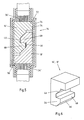
- Fig. 1 shows a wind turbine 2 with a nacelle 2a and a pinwheel 6.
- the nacelle 2a is rotatably mounted on a tower formed of sections 8a, 8b, 8c tower 2b.
- cable strands 10 are arranged, via which the electrical energy from the arranged in the nacelle 2a generator (not shown) to the disposed in the base of the tower 2 inverter 5 is passed.
- the cable strands 10 are shown by way of example.
- a cable harness 10a and a cable harness 10c are arranged in the section 8a.
- Several cable strands 10 can be provided per phase, so that it can definitely happen that in each case three cable strands 10a can be provided in a section 8a per phase.
- the respective cables 10b, 10d are provided in the section 8 c further cable strands 10 are provided.
- the sections 8 are delivered prefabricated with cables 10.
- the cables 10 are already contained in the sections 8 at the beginning of the assembly and must be electrically and mechanically connected to each other at the section boundaries 12.
- the connection of the cable 10 with each other is realized via the connection systems 14, as will be described in more detail below.
- a jumper cable 16 may connect the cables 10a, 10b across the section boundary 12.
- the bridging cable 15 can have complementary connecting pieces to the connecting pieces which are respectively arranged at the ends of the cables.
- first cable 10c to have a first connecting piece 16 and a second cable 10d to have a second connecting piece 18 complementary thereto.
- the cables 10c, 10d may be made up in such a way that they protrude beyond the section boundary 12.
- the connection system 14 can be plugged together at the section boundary 12, so that the cables 10c and 10d are directly mechanically and electrically connected to each other.
- connection systems 14 may be formed of two connecting pieces that are shaped complementary to each other.
- a cable end of a cable 10a to recognize which has a stripped end 20.
- the cable 10a is preferably formed of aluminum strands or wires, which are pressed by the sleeve 22 also formed of aluminum.
- the sleeve 22 can be pressed onto the strands. Subsequently, the sleeve 22 can be abraded, milled off or cut off at the end side together with the strands.
- the end face 24 thus formed can then be connected to the end face of the connecting piece 18 be connected by means of welding, preferably rotational friction welding, cohesively.
- the end face 24 may form a connection surface for the cable 10a.
- the connecting piece 18 is preferably formed of aluminum.
- the sleeve 22 as well as the connector 18 may be nickel plated and tinned.
- the connecting piece 18 When welding the connecting piece 18 with the sleeve 22 and the free ends of the strands 2, the surface coatings are broken.
- a corresponding connection is also possible on the connecting piece 16 on the cable 10b.
- the welded to the cables 10 a, 10 b connecting pieces 16, 18 are in the FIG. 2 shown. It can be seen that the connecting pieces 16, 18 are hooked into one another.
- the connecting pieces 16, 18 each extend parallel to the longitudinal axis 11a, 11b of a respective cable 10a, 10b.
- the connector 16 is connected to the connection surface 32 with the cable 10b.
- the connector 18 is connected to the connection surface 34 with the cable 10 a. Starting from the connecting surfaces 32, 34, the respective connecting pieces 16, 18 extend parallel to the longitudinal axes 11a, 11b, which in the illustrated, connected state of the connection system 14 are collinear with one another.
- Fig. 3 shows a view of the connecting piece 16.
- the connecting piece 16 is integrally formed from a flat part educated. Starting from the connecting surface 32, the connecting piece 16 has a first web 36 and a second web 38, which are interconnected via a groove bottom 40. The webs 36, 38 and the groove bottom 40 form a groove 42. The groove 42 is bounded by the groove bottom 40 and the groove walls 44, 46. As can be seen, the groove wall 46 disposed in the web facing the cable groove 46 is in the direction of Connecting surface 32 inclined. Starting from the groove base 40, the groove 42 opens by the inclination of the groove wall 46th
- FIG. 3 web shown 38 may also serve as a projection for engaging in a groove of a connecting piece 18, as shown in FIG. 2 can be seen.
- the second connecting piece 18 is a flat part and has, starting from the connecting surface 34 in the direction of the longitudinal axis 11 b, a first web 50, a groove bottom 52 and a second web 54.
- the webs 50, 54 and the groove bottom 52 form a groove 60.
- the groove 60 has next to the groove bottom 52 two groove walls 62, 64th
- the web 54 has a lateral surface 66, which is arranged on the side facing away from the connecting surface 34 of the connecting piece 18.
- the lateral surface 66 is inclined in the direction of the longitudinal axis 11a.
- the web 54 forms a projection 68.
- the connecting piece 18 is moved in the direction of the longitudinal axis 11a toward the connecting piece 16.
- the lateral surface 66 comes into contact with the web 38.
- the fact that the lateral surface 66 is inclined, the connector can be 18 lightly push on the bridge 38.
- the web 54 then slides over the web 38 until the web 54 or the projection 68 engages in the groove 40. Parallel to the web 38 engages in the groove 60 a.
- the connecting pieces 16, 18 hook into each other as in the FIG. 2 can be seen.
- grooves 42, 60 extend in a direction parallel to a plane perpendicular to the longitudinal axes 11a, 11b and completely break through the respective connectors 16, 18 and are not bounded by lateral sidewalls.
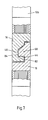
- FIG. 5 shows another example of a connection system 14.
- the connecting pieces 16 ', 18' correspond approximately to the connecting pieces 16, 18.
- the connecting pieces 16 ', 18' congruent and / or complementary to each other.
- FIG. 6 shows a view of these connectors 16 ', 18'. It can be seen that the lateral surface 66 facing away from the connection surface is inclined in the direction of the longitudinal axis 11a, 11b and the web 54 forms the projection 68. Furthermore, it can be seen that the groove surface 46 facing the connection surface 11a, 11b is inclined in the direction of the longitudinal axis. Like in the FIG. 5 can be seen, engages the respective projection 68 of the respective connecting piece 16 ', 18' in the respective groove 40 of the respective other connector 16 ', 18' a.
- the connecting pieces 16 ', 18' have flanges 70, 72. At these flanges 70, 72 is an insulating sleeve 74 at.
- the Insulation sleeve 74 may be formed as a screw cap or bayonet closure.
- a metal cage 76 is slipped, which also bears against the flanges 70, 72. By means of the metal cage 76, an electromagnetic shielding of the connection system 14 is ensured.
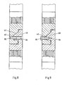
- FIG. 7 shows a connection system with connectors 16, 18 approximately corresponding to FIG. 2 ,
- an undercut 82 is provided in the groove wall 44 of the connecting piece 16.
- the undercut 82 extends in the direction of the groove and extending from the cable 10b pioneering in the groove wall 44.
- a projection 68 arranged on the locking hook 84 engages a projection 68 arranged on the locking hook 84.
- FIG. 8 Another assurance of removal of the connector 18 from the connector 16 and the projection 68 from the groove 42 is in FIG. 8 shown.
- a screw 86 is arranged, which is screwed into a thread 88 in the groove bottom 40 of the groove 42. Also, the screw 86 prevents removal of the projection 68 from the groove 42 normal to the groove bottom 40th
- FIG. 9 shows another way in which, unlike in FIG. 8 the screw 86 does not pierce the projection 68 but the groove bottom 40.
- the screw 86 is screwed in a thread 90 on the projection 68.
Landscapes
- Engineering & Computer Science (AREA)
- Mechanical Engineering (AREA)
- Sustainable Development (AREA)
- Sustainable Energy (AREA)
- Chemical & Material Sciences (AREA)
- Combustion & Propulsion (AREA)
- Life Sciences & Earth Sciences (AREA)
- General Engineering & Computer Science (AREA)
- Connections Effected By Soldering, Adhesion, Or Permanent Deformation (AREA)
- Details Of Connecting Devices For Male And Female Coupling (AREA)
- Cable Accessories (AREA)
- Processing Of Terminals (AREA)
- Installation Of Indoor Wiring (AREA)
Description
Der Gegenstand betrifft ein elektrisches Verbindungssystem einer Einrichtung zur Gewinnung elektrische Energie aus regenerativen Quellen, insbesondere einer Windkraftanlage mit einem an einem Ende eines ersten Kabels anordenbaren ersten Verbindungsstück, und einem an einem Ende eines zweiten Kabels anordenbaren zweiten Verbindungsstück.The subject matter relates to an electrical connection system of a device for obtaining electrical energy from regenerative sources, in particular a wind turbine having a first connector which can be arranged at one end of a first cable, and a second connector which can be arranged at one end of a second cable.
Elektrische Energiegewinnungseinrichtungen, wie beispielsweise Windkraftanlagen, werden heutzutage mit Kupfer- oder Aluminiumkabeln bestückt. Aufgrund des steigenden Kupferpreises setzt sich jedoch die Bestückung mit Aluminiumkabeln immer mehr durch. Insbesondere bei Windkraftanlagen, die zwischen 50m und 200m hoch sind, werden große Mengen Kabel benötigt, so dass das Einsparpotential bei der Verwendung von Aluminiumkabeln erheblich ist.Electric power generation equipment, such as wind turbines, are now equipped with copper or aluminum cables. Due to the rising price of copper, however, the assembly of aluminum cables is becoming increasingly popular. In particular, wind turbines that are between 50m and 200m high, large quantities of cables are needed, so that the potential savings in the use of aluminum cables is significant.
Durch die große Höhe der Windkraftanlagen bedingt ist es jedoch unmöglich, die im Turm der Windkraftanlage angeordneten Generatoren mit einem einzigen Kabel mit dem im Sockel der Anlage angeordneten Umrichter zu verbinden. Daher werden in einzelnen Turmsegmenten jeweils Kabel vormontiert. Um die Kabel der einzelnen Segmente miteinander zu verbinden, müssen diese an den Segmentgrenzen elektrisch leitend verbunden werden. Solange Kupferkabel zum Einsatz kommen, ist ein Vercrimpen oder Verschrauben der Kabel unproblematisch, da sich auf der Kupferoberfläche kein die elektrische Leitfähigkeit negativ beeinflussendes Material ablagert, das während der Dauer des Betriebes der Windkraftanlage zu einer Verminderung der elektrischen Leitfähigkeit der Verbindung führen könnte.Due to the great height of the wind turbines conditioned, however, it is impossible to connect the arranged in the tower of the wind turbine generators with a single cable to the arranged in the base of the system inverter. Therefore, cables are pre-assembled in individual tower segments. In order to connect the cables of the individual segments with each other, they must be electrically connected at the segment boundaries. As long as copper cables are used, crimping or screwing of the cables is unproblematic since no material that negatively influences the electrical conductivity deposits on the copper surface, which during the operation of the Wind turbine could lead to a reduction in the electrical conductivity of the connection.
Bei der Verwendung von Aluminiumkabeln ist dies jedoch anders. Eine Crimpverbindung muss vor Umwelteinflüssen geschützt werden. Ferner muss verhindert werden, dass sich an den Übergangsstellen Aluminiumoxid bildet, welches den Übergangswiderstand erheblich erhöht. Bei Kabeln, die mehrere 10 A oder sogar mehreren 100 A tragen, ist ein elektrischer Übergangswiderstand stets mit hoher Verlustleistung verbunden. Daher muss versucht werden, den elektrischen Übergangswiderstand zwischen den Kabeln an der Verbindungsstelle so gering wie möglich zu gestalten und auf der anderen Seite eine möglichst schnell montierbare Verbindungstechnologie zur Verfügung zu stellen.However, this is different when using aluminum cables. A crimp connection must be protected against environmental influences. Furthermore, it must be prevented that aluminum oxide forms at the transition points, which considerably increases the contact resistance. For cables that carry several 10 A or even several 100 A, an electrical contact resistance is always associated with high power dissipation. Therefore, it must be tried to make the electrical contact resistance between the cables at the connection point as low as possible and to provide on the other side as quickly as possible mountable connection technology.
Heutzutage wird aber an den Sektionsgrenzen ein Vercrimpen der Kabel der jeweiligen Sektionen vorgeschlagen. Hierbei wird eine Crimphülse auf die Kabel aufgeschraubt. Hierzu muss der Mechaniker in den Turm klettern, an der Sektionsgrenze die Kabel ablängen und abisolieren. Anschließend muss der Mechaniker die abisolierten Enden der Kabel mit einer Leitpaste bestreichen. Hierdurch soll verhindert werden, dass sich an den Oberflächen der Aluminiumlitzen Aluminiumoxid bildet. Anschließend muss der Mechaniker die Crimphülse auf die freien Kabelenden aufschieben und in einem aufwendigen Prozess mit vielen Schrauben mit den Kabeln verschrauben. Die so geschilderte Montage ist zeit- und kostenintensiv. Außerdem ist die Güte der elektrischen Verbindung nicht stabil, dass heißt, dass über die Zeit der elektrische Übergangswiderstand steigt, da die Leitpaste nicht vollständig die Bildung von Aluminiumoxid verhindern kann.Today, however, at the section boundaries a crimping of the cables of the respective sections is proposed. Here, a crimp barrel is screwed onto the cable. To do this, the mechanic must climb into the tower, cut the cables to length on the section boundary and strip them. Afterwards, the mechanic must coat the stripped ends of the cables with a conductive paste. This is to prevent aluminum oxide from forming on the surfaces of the aluminum strands. Afterwards, the mechanic has to push the crimp barrel onto the free cable ends and screw it with the cables in a complex process with many screws. The so described assembly is time consuming and costly. In addition, the quality of the electrical connection is not stable, that is, over time the electrical contact resistance increases because the conductive paste can not completely prevent the formation of aluminum oxide.
Außerdem ist eine ausreichend große Zugentlastung an der Verbindungsstelle vorzusehen. Bei Kabelsträngen von mehreren zehn Metern Länge treten enorme Zugkräfte an der Verbindungsstelle auf. Daher ist neben einer elektrisch gut leitenden Verbindung auch eine mechanisch stabile Verbindung notwendig. Dies wird heutzutage mit Hilfe von massiven Crimpverbindungen und Verschraubungen der Kabelseelen sichergestellt.In addition, a sufficiently large strain relief at the connection point should be provided. For cable harnesses of several tens of meters in length, enormous tensile forces occur at the connection point. Therefore, in addition to a good electrical connection and a mechanically stable connection is necessary. This is ensured today with the help of massive crimp connections and cable glands.
Die
Aus diesem Grunde lag dem Gegenstand die Aufgabe zugrunde, ein elektrisches Verbindungssystem zur Verfügung zu stellen, welches in besonders einfacher Weise montierbar ist und dabei gleichzeitig eine mechanische Zugentlastung an der Verbindungsstelle gewährleistet.For this reason, the object of the present invention was to provide an electrical connection system available, which is mounted in a particularly simple manner, while ensuring a mechanical strain relief at the junction.
Diese Aufgabe wird gegenständlich durch ein Verbindungssystem nach Anspruch 1 gelöst.This object is achieved objectively by a connection system according to claim 1.
Es ist erkannt worden, dass das Vercrimpen und Verschrauben der Aluminiumkabel fehlerträchtig ist und sich dabei kein genügend kleiner Übergangswiderstand realisieren lässt. Auch ist erkannt worden, dass das bekannte Montageverfahren zu zeitaufwendig ist. Da die mechanische Sicherung gegenüber Zugkräften in Richtung der Kabellängsachsen gewährleistet sein muss, müssen die Verschraubungen mit Schrauben mit großem Durchmesser durchgeführt werden. Während der Montage ist es notwendig, die Zugkräfte zu kompensieren und die Kabel an der Verbindungsstelle zu fixieren. Hierzu sind aufwändige Sicherungsmaßnahmen vor der Montage notwendig, die zeitintensiv sind. Für den Monteur ist es aufwändig, die Kabel in der zu verbindenden Position zu fixieren. All diese Probleme werden gegenständlich gelöst.It has been recognized that the crimping and screwing of the aluminum cables is error prone and can not realize a sufficiently small contact resistance. It has also been recognized that the known assembly process is too time consuming. Since the mechanical protection must be ensured against tensile forces in the direction of the cable longitudinal axes, the screw connections must be carried out with large diameter screws. During assembly, it is necessary to compensate for the tensile forces and fix the cables at the joint. For this purpose, elaborate security measures before installation are necessary, which are time-consuming. For the mechanic it is complex, the Fix the cable in the position to be connected. All these problems are solved objectively.
Die Verbindungsstücke haben an den jeweiligen Kabeln zugewandten Seiten Anschlussflächen. An den Anschlussflächen der jeweiligen Verbindungsstücke können die Kabel vorzugsweise stoffschlüssig angeordnet werden. Insbesondere in einem vorkonfektionierten Zustand können die Kabel an den Anschlussflächen angeschweißt sein. Hierzu eignen sich insbesondere Reibschweißverfahren, wie nachfolgend noch dargestellt werden wird. Andererseits sind jedoch auch Widerstandschweißverfahren geeignet, um Verbindungen zwischen den stirnseitigen Enden der Kabel und den Verbindungsstücken bzw. den Anschlussflächen der Verbindungsstücke herzustellen.The connectors have connection surfaces on the sides facing the respective cables. At the connecting surfaces of the respective connecting pieces, the cables can preferably be arranged cohesively. In particular, in a prefabricated state, the cables can be welded to the connection surfaces. For this purpose, in particular friction welding, as will be shown below. On the other hand, however, resistance welding methods are also suitable for making connections between the front ends of the cables and the connecting pieces or connecting surfaces of the connecting pieces.
Das erste Verbindungsstück erstreckt sich in Richtung einer Anschlussfläche für ein Ende des ersten Kabels. In dieser Erstreckungsrichtung bildet das erste Verbindungsstück eine Längsachse aus.The first connector extends toward a pad for one end of the first cable. In this extension direction, the first connector forms a longitudinal axis.
Das zweite Verbindungsstück erstreckt sich in Richtung einer zweiten Anschlussfläche für ein zweites Ende des ersten Kabels oder ein Ende des zweiten Kabels. In dieser Erstreckungsrichtung bildet das zweite Verbindungsstück ebenfalls eine Längsachse aus.The second connector extends toward a second pad for a second end of the first cable or an end of the second cable. In this extension direction, the second connector also forms a longitudinal axis.
Das erste Verbindungsstück hat eine Aufnahme zur Aufnahme eines Vorsprungs. Der Vorsprung ist an dem zweiten Verbindungsstück gebildet. Durch Ineinanderschieben des Vorsprungs in die Aufnahme ist es möglich, eine elektrisch leitende Verbindung zwischen den beiden Verbindungsstücken und somit zwischen den an den Verbindungsstücken angeordneten Kabeln herzustellen.The first connector has a receptacle for receiving a projection. The projection is formed on the second connector. By telescoping the projection into the receptacle, it is possible to have an electrically conductive connection between the make two connectors and thus between the arranged on the connectors cables.
Eine besonders leichte Montage ist dann möglich, wenn die Aufnahme durch eine sich in einer Ebene senkrecht zur ersten Längsachse erstreckende Nut gebildet ist, wobei die Nut in ihrer Erstreckungsrichtung das erste Verbindungsstück durchbricht. Es kann sich in dem ersten Verbindungsstück eine Nut erstrecken, die quer zur Längsachse verläuft. Diese Nut erstreckt sich über das gesamte Verbindungsstück und durchbricht dieses an den jeweiligen Seiten in ihrer Erstreckungsrichtung.A particularly easy assembly is possible if the receptacle is formed by a groove extending in a plane perpendicular to the first longitudinal axis, wherein the groove in its direction of extent breaks through the first connector. It may extend in the first connector, a groove which is transverse to the longitudinal axis. This groove extends over the entire connecting piece and breaks through this at the respective sides in their direction of extension.
Der Vorsprung erstreckt sich in einer Ebene senkrecht zur zweiten Längsachse.The projection extends in a plane perpendicular to the second longitudinal axis.
Im verbundenen Zustand ist der Vorsprung in der Nut eingesetzt. Dann verlaufen Nut und Vorsprung in derselben Erstreckungsrichtung. Vorzugsweise sind dann die Längsachsen parallel, vorzugsweise kollinear zueinander.In the connected state, the projection is inserted in the groove. Then run groove and projection in the same direction of extent. Preferably, then the longitudinal axes are parallel, preferably collinear to each other.
Eine erste Nutwand ist in Richtung der ersten Längsachse geneigt ist und eine Mantelfläche des Vorsprungs ist in Richtung der zweiten Längsachse geneigt. Hierdurch wird ein ineinander Haken von Vorsprung und Nut deutlich erleichtert. In der Art eines Schnappverschlusses kann der Vorsprung über eine Nutwand geschoben werden, um dann anschließend in der Nut einzurasten. Durch die Neigung der Nutwand und die Neigung des Vorsprungs ist ein übereinander Schieben der Verbindungsstücke erleichtert, da diese ineinander "gleiten" können. Dies erleichtert dem Monteur das Verbinden der Verbindungsstücke miteinander.A first groove wall is inclined in the direction of the first longitudinal axis and a lateral surface of the projection is inclined in the direction of the second longitudinal axis. As a result, an interlocking hook of projection and groove is much easier. In the manner of a snap closure, the projection can be pushed over a groove wall, in order then subsequently to engage in the groove. Due to the inclination of the groove wall and the inclination of the projection, a superimposition of the connecting pieces is facilitated since they can "slide" into one another. This facilitates the fitter connecting the connectors together.
Es ist erkannt worden, dass ein elektrisches Verbinden der Verbindungsstücke durch Ineinanderstecken von Vorsprung und Aufnahme dann leicht ist, wenn Vorsprung und Aufnahme in einer Ebene senkrecht zur Längsachse der Verbindungsstücke verlaufen. In diesem Fall kann ein Monteur die Kabel an den Sektionsgrenzen besonders einfach miteinander montieren. Es ist lediglich notwendig, die Verbindungsstücke miteinander zu verbinden, wobei dies durch Ineinanderschieben von Vorsprung und Aufnahme geschieht.It has been recognized that electrical connection of the connectors by nesting of projection and receptacle is easy when projection and receptacle are in a plane perpendicular to the longitudinal axis of the connectors. In this case, a fitter can particularly easily mount the cables to each other at the section borders. It is only necessary to connect the connectors together, this being done by telescoping projection and recording.
Dadurch, dass Vorsprung und Aufnahme in einer Ebene senkrecht zur Längsachse verlaufen, ergibt sich eine natürliche Zugentlastung an der Verbindungsstelle. Der Vorsprung liegt an einer Nutwand an. Die Nutwand nimmt die Zugkräfte, die in Richtung der Längsachse wirken, auf, und leitet diese in das mit dem ersten Verbindungsstück verbundene Kabel ein.The fact that projection and receiving in a plane perpendicular to the longitudinal axis, there is a natural strain relief at the junction. The projection abuts a groove wall. The groove wall absorbs the tensile forces acting in the direction of the longitudinal axis, and introduces them into the cable connected to the first connector.
Es hat sich gezeigt, dass die Verbindungsstücke besonders einfach miteinander verbunden werden können und gleichzeitig eine sehr gute Zugentlastung gewährleistet werden kann, wenn das erste Verbindungsstück und das zweite Verbindungsstück jeweils eine Nut und einen Vorsprung aufweisen. Somit kann jeweils ein Vorsprung eines Verbindungsstücks in der jeweils dazu korrespondierenden Nut des anderen Verbindungsstücks verrasten und eine Zugentlastung gewähren. Eine Nut ist regelmäßig durch einen Nutgrund sowie zwei Nutwände gebildet. Es ist erkannt worden, dass jeweils eine Nutwand auch als Vorsprung dienen kann, indem der die Nutwand bildende Steg den Vorsprung bildet. Hierbei ist besonders von Vorteil, wenn der auf der der jeweiligen Anschlussfläche abgewandten Seite des Verbindungsstück angeordnete Steg, der die Nutwand bildet, den Vorsprung bildet.It has been shown that the connecting pieces can be particularly easily connected to each other and at the same time a very good strain relief can be ensured if the first connector and the second connector each have a groove and a projection. Thus, in each case a projection of a connecting piece in the respective corresponding groove of the other connecting piece engage and provide a strain relief. A groove is regularly formed by a groove bottom and two groove walls. It has been recognized that in each case a groove wall can also serve as a projection in that the web forming the groove wall forms the projection. It is particularly advantageous if the on the side facing away from the respective pad the connecting piece arranged web, which forms the groove wall, forms the projection.
Die Zugentlastung in Längsrichtung wird durch das Aneinanderliegen von Vorsprung und Nut zwischen den Verbindungsstücken gewährleistet. In Richtung der Längsachse wirkende Kräfte werden von dem Vorsprung auf die Nutwand bzw. den die Nutwand bildenden Steg geleitet und somit in das jeweils andere Verbindungsstück bzw. Kabel.The strain relief in the longitudinal direction is ensured by the abutment of projection and groove between the connectors. In the direction of the longitudinal axis acting forces are guided by the projection on the groove wall or the groove wall forming web and thus in the other connector or cable.
Um die elektrische Verbindung zwischen den Verbindungsstücken gegenüber Scher- und Querkräften zu sichern, wird gemäß der Erfindung vorgeschlagen, dass im verbunden Zustand der Vorsprung in der Nut durch ein Sicherungselement befestigt ist. Das Sicherungselement ist bevorzugt derart, dass dieses eine Druckkraft auf den Vorsprung in Richtung des Nutgrundes ausübt. Hierdurch wird verhindert, dass der Vorsprung aus der Nut heraus bewegt werden kann. Das Sicherungselement fixiert den Vorsprung in der Nut.In order to secure the electrical connection between the connectors against shear and shear forces, it is proposed according to the invention that in the connected state, the projection is secured in the groove by a securing element. The securing element is preferably such that it exerts a compressive force on the projection in the direction of the groove bottom. This prevents that the projection can be moved out of the groove. The securing element fixes the projection in the groove.
Gemäß der Erfindung wird vorgeschlagen, dass das Sicherungselement den Nutgrund durchstößt und in dem Vorsprung befestigt ist. Auch ist es möglich, dass das Sicherungselement den Vorsprung durchstößt und in dem Nutgrund befestigt ist. Dadurch, dass das Sicherungselement entweder den Nutgrund oder den Vorsprung durchstößt und in dem jeweils korrespondieren Vorsprung bzw. Nutgrund befestigt ist, kann in besonders einfacher Weise eine in Richtung des Nutgrunds wirkende Kraft auf den Vorsprung ausgeübt werden.According to the invention it is proposed that the securing element pierces the groove base and is secured in the projection. It is also possible that the securing element pierces the projection and is secured in the groove bottom. Characterized in that the securing element pierces either the groove base or the projection and is secured in the respective corresponding projection or groove base, a force acting in the direction of the groove bottom force can be exerted on the projection in a particularly simple manner.
Besonders vorteilhaft ist dies möglich, wenn das Sicherungselement eine Schraube ist. Es ist erkannt worden, dass bei der Verwendung von Aluminium oder Aluminiumlegierungen für die Sicherungselemente ein Sichern mittels einer Schraube problematisch ist, wenn die Schraube mit einem zu großen Drehmoment angezogen wird. In diesem Fall kann es zu einem Fließen des Aluminiums kommen und die mittels der Schraube miteinander befestigten Teile können sich voneinander lösen. Auch können Gewinde abgeschert werden. Aus diesem Grunde wird vorgeschlagen, dass eine Abreißschraube oder eine mit einem definierten Drehmoment befestigte Schraube zum Befestigen der Sicherungselemente verwendet wird. Mit Hilfe eines Drehmomentsschlüssels lässt sich eine Schraube mit einem definierten Drehmoment anziehen, so dass verhindert wird, dass das Gewinde an der Schraube oder den Verbindungsstücken abgeschert wird.This is particularly advantageously possible if the securing element is a screw. It has been recognized that when using aluminum or aluminum alloys for the securing elements securing by means of a screw is problematic when the screw is tightened with too high a torque. In this case, it may come to a flow of aluminum and fastened together by means of the screw parts can be separated from each other. Also threads can be sheared off. For this reason, it is proposed that a tear-off screw or a screw fastened with a defined torque is used for fastening the securing elements. Using a torque wrench, a screw can be tightened with a defined torque to prevent it from shearing off the threads on the screw or connectors.
Besonders einfach lässt sich der Vorsprung in die Nut schieben, wenn die in Richtung der ersten Längsachse geneigte Nutwand auf der dem Kabel zugewandten Seite der Nut angeordnet ist. In diesem Fall ist der dazu korrespondierende Vorsprung auf der dem Kabel abgewandten Seite geneigt und lässt sich somit besonders einfach über die Nutwand schieben und in der Nut einrasten. Auch wird vorgeschlagen, dass die in Richtung der ersten Längsachse geneigten Nutwand auf der dem Kabel abgewandten Seite der Nut angeordnet ist.The projection can be pushed into the groove in a particularly simple manner if the groove wall inclined in the direction of the first longitudinal axis is arranged on the side of the groove facing the cable. In this case, the corresponding projection on the side facing away from the cable is inclined and thus can be particularly easily slide over the groove wall and engage in the groove. It is also proposed that the groove wall inclined in the direction of the first longitudinal axis is arranged on the side of the groove facing away from the cable.
In diesem Fall ist die Nutwand von dem Kabel wegweisend geneigt. Im vorherigen Fall ist die Nutwand ausgehend vom Nutgrund in Richtung des Kabels geneigt.In this case, the groove wall of the cable is groundbreaking inclined. In the previous case, the groove wall is inclined starting from the groove bottom in the direction of the cable.
Auch wird vorgeschlagen, dass die Nutwand auf der dem Kabel abgewandten Seite der Nut parallel zur Ebene senkrecht zur Längsachse verläuft. Auch ist es möglich, dass die Nutwand auf der dem Kabel zugewandten Seite der Nut parallel zur Ebene senkrecht zur Längsachse verläuft.It is also proposed that the groove wall on the side facing away from the cable of the groove is parallel to the plane perpendicular to the longitudinal axis. It is also possible that the groove wall on the cable side facing the groove parallel to the plane perpendicular to the longitudinal axis.
Gemäß einem Ausführungsbeispiel wird vorgeschlagen, dass die Verbindungsstücke aus Aluminium oder Legierungen davon gebildet sind und dass die Kabel aus Aluminium, Kupfer oder Legierungen gebildet sind. Die Verwendung von Aluminium erlaubt ein besonders kostengünstiges Verkabeln von Windkraftanlagen, da Aluminium erheblich günstiger als Kupfer ist. Durch die Verwendung von Aluminium ergibt sich darüber hinaus ein erheblicher Gewichtsvorteil, so dass die an der Verbindung auftretenden Zugkräfte geringer sind.According to one embodiment, it is proposed that the connecting pieces are formed from aluminum or alloys thereof and that the cables are formed from aluminum, copper or alloys. The use of aluminum allows a particularly cost-effective wiring of wind turbines, since aluminum is considerably cheaper than copper. In addition, the use of aluminum results in a significant weight advantage, so that the tensile forces occurring at the connection are lower.
Um zu verhindern, dass der Übergangswiderstand an den Verbindungsstücken auf Grund von Aluminiumoxid negativ beeinflusst wird, wird vorgeschlagen, dass die Verbindungsstücke metallisch beschichtet sind. Eine metallische Beschichtung kann hierbei ein Unternickeln und/oder ein Verzinnen sein. Dies verhindert die Bildung von Aluminiumoxid auf der Oberfläche der Verbindungsstücke, wenn diese aus Aluminium gebildet sind. Eine metallische Beschichtung mit Silber oder anderer Metalle ist ebenfalls möglich, insbesondere wenn die Übergangswiderstände gering gehalten werden müssen.In order to prevent the contact resistance at the connectors due to alumina is adversely affected, it is proposed that the connectors are coated with metal. A metallic coating may in this case be a nickel-plating and / or a tinning. This prevents the formation of aluminum oxide on the surface of the connectors when formed of aluminum. A metallic coating with silver or other metals is also possible, especially if the contact resistance must be kept low.
Gemäß einem Ausführungsbeispiel wird vorgeschlagen, dass das Verbindungsstück mit dem Kabel mittels Stumpfschweißen, insbesondere mittels Reibschweißen stoffschlüssig verbunden ist. Wie bereits eingangs erläutert, ist eine Montage besonders einfach, wenn die Verbindungsstücke keilförmig ineinander greifen, wie auch vorgeschlagen wird. Durch das keilförmige Ineinandergreifen werden gleichzeitig eine elektrische Verbindung und eine mechanische Zugentlastung ermöglicht.According to one exemplary embodiment, it is proposed that the connecting piece is materially connected to the cable by means of butt welding, in particular by means of friction welding. As already explained at the beginning, an assembly is particularly simple if the connecting pieces engage in one another like a wedge, as is also suggested. Due to the wedge-shaped mesh at the same time a electrical connection and a mechanical strain relief allows.
Um die Verbindung der Verbindungsstücke zu sichern, wird vorzugsweise eine Isolationshülse um die Verbindungsstücke gelegt. Um der Isolationshülse zu ermöglichen, Zugkräfte in Längsrichtung aufzunehmen, muss diese an den Verbindungsstücken anliegen. Aus diesem Grunde weisen die Verbindungsstücke gemäß einem Ausführungsbeispiel in einer Ebene senkrecht zur Längsachse verlaufende, zumindest teilweise um die Verbindungsstücke umlaufende Flansche auf. An diesen Flanschen können Ringschultern von Isolationshülsen anliegen.In order to secure the connection of the connecting pieces, an insulating sleeve is preferably placed around the connecting pieces. In order to allow the insulating sleeve to absorb tensile forces in the longitudinal direction, this must be applied to the connecting pieces. For this reason, the connecting pieces according to an embodiment in a plane perpendicular to the longitudinal axis extending, at least partially around the connecting pieces circumferential flanges. Ring shoulders of insulating sleeves can rest against these flanges.
Die Isolationshülse verhindert, dass auf die elektrische Verbindung an den Verbindungsstücken Umwelteinflüsse wirken. Die Isolationshülse kann so ausgestaltet sein, dass sie die elektrische Verbindung an den Verbindungsstücken abdichtet, so dass Feuchtigkeit nicht an die elektrische Verbindung heranlangen kann. Hierzu ist es beispielsweise möglich, dass die Isolationshülse feuchtigkeitsdicht an der Isolation des Kabels im Bereich des Kabelendes anliegt. Dies kann beispielsweise durch die Verwendung eines O-Rings realisiert werden. Auch ist es möglich, dass ein Schrumpfschlauch um die Isolationshülse gelegt wird und an die Isolation des Kabels angeschrumpft wird.The insulating sleeve prevents environmental influences from acting on the electrical connection at the connecting pieces. The insulating sleeve may be configured to seal the electrical connection to the connectors so that moisture can not reach the electrical connection. For this purpose, it is possible, for example, that the insulation sleeve bears moisture-tight on the insulation of the cable in the region of the cable end. This can be realized for example by the use of an O-ring. It is also possible that a shrink tube is placed around the insulation sleeve and is shrunk to the insulation of the cable.
Gemäß einem Ausführungsbeispiel wird vorgeschlagen, dass eine Isolationshülse an den Flanschen angreift und die Verbindungsstücke in Längsrichtung aneinander hält.According to one embodiment, it is proposed that an insulating sleeve acts on the flanges and holds the connecting pieces in the longitudinal direction against each other.
Gemäß einem Ausführungsbeispiel wird vorgeschlagen, dass die Isolationshülse zweiteilig ist, wobei ein erster Teil an dem Flansch des ersten Verbindungsstücks angeordnet ist und ein zweiter Teil an dem Flansch des zweiten Verbindungsstücks angeordnet ist und wobei die Teile verliersicher miteinander mechanisch verbindbar sind, derart, dass im verbundenen Zustand eine durch die Teile auf die Verbindungsstücke parallel zur Längsachse ausgeübte Kraft die Verbindungsstücke in Längsachse aufeinander zu drückt. Hierdurch entsteht eine weitere Zugentlastung in Längsrichtung.According to one embodiment, it is proposed that the insulating sleeve is in two parts, wherein a first part is arranged on the flange of the first connector and a second part is arranged on the flange of the second connector and wherein the parts are captive mechanically connected to one another, such that in Connected state a force exerted by the parts on the connecting pieces parallel to the longitudinal axis force pushes the connecting pieces in the longitudinal axis towards each other. This creates a further strain relief in the longitudinal direction.
Die Teile der Isolationshülse lassen sich beispielsweise miteinander verschrauben oder sind als Bajonettverschluss gebildet, so dass ein Teil in dem anderen Teil verrastet.The parts of the insulating sleeve can be screwed together, for example, or are formed as a bayonet closure, so that one part locked in the other part.
Zum Befestigen der Isolationshülse bzw. der Teile miteinander müssen diese, wie beschrieben, vorzugsweise miteinander verschraubt werden. Um dieses Verschrauben zu erleichtern, ist an zumindest einem Teil eine Nutmutter zur Aufnahme eines Hakenschlüssels angeordnet, wobei mittels der Nutmutter das erste Teil mit dem zweiten Teil verschraubbar ist.To secure the insulating sleeve or the parts with each other, they must, as described, preferably be screwed together. In order to facilitate this screwing, a groove nut for receiving a hook key is arranged on at least one part, wherein by means of the groove nut, the first part with the second part is screwed.
Auch wird vorgeschlagen, dass das isolierende Gehäuse durch einen Metallkäfig, insbesondere einen Stahlblechkäfig umgeben ist. Es hat sich gezeigt, dass durch die Verwendung eines Metallkäfigs zum Einen eine erhöhte mechanische Festigkeit gegenüber Zugkräften gewährleistet werden kann und zum Anderen die Verbindungen gegenüber elektromagnetischer Störungen unempfindlicher gemacht werden kann. Der Metallkäfig greift vorzugsweise an dem isolierenden Gehäuse im Bereich der Flansche an, so dass auch über den Metallkäfig Zugkräfte aufgenommen werden können.It is also proposed that the insulating housing is surrounded by a metal cage, in particular a sheet steel cage. It has been shown that by using a metal cage on the one hand, an increased mechanical strength against tensile forces can be ensured and on the other hand, the compounds against electromagnetic interference can be made insensitive. The metal cage preferably acts on the insulating housing in the region of the flanges, so that tensile forces can also be absorbed via the metal cage.
Eine weitere mechanische Fixierung des Vorsprungs in der Nut kann dadurch erreicht werden, dass am Nutgrund ein sich in Längsachse erstreckender Hinterschnitt vorgesehen ist. Der Hinterschnitt ist vorzugsweise in der Nutwand im Bereich des Nutgrunds angeordnet und weist vorzugsweise von dem Kabel des Verbindungsstücks fort.A further mechanical fixation of the projection in the groove can be achieved by providing an undercut extending in the longitudinal axis on the groove base. The undercut is preferably arranged in the groove wall in the region of the groove base and preferably points away from the cable of the connecting piece.
Ein hierzu korrespondierender Rasthaken kann an einer Spitze des Vorsprungs angeordnet sein und den Hinterschnitt hintergreifen. Hierdurch können Zugkräfte normal zur Fläche des Nutgrunds durch den Hinterschnitt und den Rasthaken kompensiert werden. Dies erschwert ein herauslösen des Vorsprungs normal zum Nutgrund aus der Nut.A corresponding latching hook can be arranged on a tip of the projection and engage behind the undercut. As a result, tensile forces normal to the surface of the groove bottom can be compensated by the undercut and the latching hook. This makes it difficult to detach the protrusion normal to the groove base from the groove.
Auch ist es möglich, dass die vorkonfektionierten Kabel in den jeweiligen Sektionen kurz vor der Sektionsgrenze abgelängt und mit einem der Verbindungsstücke versehen sind. Dann kann die Sektionsgrenze mit einem Verbindungskabel überbrückt werden, welches jeweils zu dem an den Sektionsgrenzen vorkonfektionierten Kabel komplementäre Verbindungsstücke aufweist. Der Mechaniker muss dann lediglich das Verbindungskabel in die Nut oder den Vorsprung der jeweiligen Kabelenden der vorkonfektionierten Kabel einschieben und erhält somit eine mechanische und elektrische Verbindung der Kabel untereinander.It is also possible that the prefabricated cables are cut to length in the respective sections shortly before the section boundary and provided with one of the connecting pieces. Then, the section boundary can be bridged with a connecting cable, which has in each case complementary to the cable at the section boundaries pre-assembled cables. The mechanic then has to insert only the connecting cable into the groove or the projection of the respective cable ends of the pre-assembled cable and thus receives a mechanical and electrical connection of the cables with each other.
Die Breite des Nutgrunds und/oder die Neigung einer Nutwand kann bei einem mehrphasigen Verbindungssystem für jede Phase unterschiedlich sein. So kann beispielsweise bei einem 3-Phasensystem jeder Phase ein Vorsprung- Nut Paar mit unterschiedlichen Breiten/Neigungswinkeln zugewiesen sein. Insbesondere bei Windkraftanlagen werden pro Phase drei bis sieben Kabel verwendet, so dass neun bis 21 Kabel pro Sektion vorkonfektioniert sind. Diese Kabel müssen phasenrichtig mit den jeweiligen Kabeln der anderen Sektionen verbunden werden. Um eine Fehlverbindung zu vermeiden, kann jede Phase mit einem eigenen Paar aus Verbindungsstücken ausgestattet sein, wobei die Verbindungsstücke der einzelnen Phasen untereinander nicht komplementär sind und nicht zueinander passen. Der Mechaniker kann dann die Montage durchführen, ohne zu befürchten, dass er eine phasenunrichtige Verbindung herstellt. Es ist sichergestellt, dass die zueinander gehörenden Kabel auch elektrisch miteinander kontaktiert werden.The width of the groove bottom and / or the inclination of a groove wall may be different for each phase in a multi-phase connection system. For example, in a 3-phase system of each phase, a projection-groove pair having different widths / angles of inclination may be assigned. Especially in wind turbines are three to three per phase seven cables are used, so that nine to 21 cables per section are prefabricated. These cables must be connected in phase with the respective cables of the other sections. In order to avoid a misconnection, each phase can be equipped with its own pair of connecting pieces, the connecting pieces of the individual phases being not complementary to each other and not matching one another. The mechanic can then perform the assembly without fear that he will make a phased connection. It is ensured that the associated cables are also contacted with each other electrically.
Bei der Verwendung von Aluminiumkabeln ist zu bevorzugen, dass die Verbindungsstücke ebenfalls aus Aluminium gebildet sind. Dies hat den Vorteil, dass keine Übergangswiderstände oder Kontaktkorrosionen an den Übergängen zwischen den Kabeln und den Verbindungsstücken entstehen. Um zu verhindern, dass sich auf der Oberfläche der Verbindungsstücke Aluminiumoxid bildet, wird vorgeschlagen, dass die Oberfläche der Verbindungsstücke verzinnt ist. Auch ist es möglich, dass.die Oberfläche zunächst vernickelt und anschließend verzinnt ist. Durch die Unternickelung wird eine dauerhafte Beschichtung erreicht und die Verzinnung ermöglicht die Erzielung eines geringen Kontaktwiderstandes.When using aluminum cables, it is preferable that the connectors are also made of aluminum. This has the advantage that no contact resistances or contact corrosion occur at the junctions between the cables and the connecting pieces. In order to prevent alumina from forming on the surface of the connectors, it is proposed that the surface of the connectors be tinned. It is also possible that the surface is first nickel-plated and then tin-plated. The nickel plating achieves a durable coating and tin plating allows low contact resistance to be achieved.
Um die Verbindungsstücke sicher mit den Kabeln zu verbinden, wird vorgeschlagen, dass ein abisoliertes Kabelende in einer Hülse angeordnet ist. Insbesondere wenn die Verbindungsstücke aus Kupfer und die Kabel aus Aluminium gebildet sind, ist eine sichere Verbindungstechnik notwendig. Die Hülse kann so um die Kabelenden gepresst sein, dass die einzelnen Litzen oder Drähte des abisolierten Kabels fest verpresst sind. Anschließend kann das stirnseitige Ende der Hülse abgeschnitten oder überfräßt werden, so dass die Kabelenden an den stirnseitigen Enden der Hülse enden und frei von Aluminiumoxid sind. Anschließend kann das Verbindungsstück, welches eine dem Kabelende zugewandte Anschlussfläche aufweisen kann, mit der Hülse und dem Kabelende entlang der Anschlussfläche verschweißt werden.To securely connect the connectors to the cables, it is proposed that a stripped cable end be disposed in a sleeve. In particular, when the connectors are made of copper and the cables are made of aluminum, a secure connection technique is necessary. The sleeve may be pressed around the cable ends such that the individual strands or wires of the stripped cable are firmly pressed. Subsequently, the front end of the sleeve can be cut off or überfrässt so that the cable ends terminate at the front ends of the sleeve and are free of alumina. Subsequently, the connecting piece, which may have a terminal surface facing the cable end, can be welded to the sleeve and the cable end along the connecting surface.
Hierbei kann beispielsweise ein Reibschweißen, insbesondere ein Rotationsreibschweißen angewandt werden. Auch ist es möglich, dass ein Ultraschallschweißen oder ein Widerstandsschweißen verwendet wird, um die Verbindungsstücke mit der Hülse und den Kabelenden zu verschweißen.Here, for example, a friction welding, in particular a rotary friction welding can be applied. It is also possible that ultrasonic welding or resistance welding is used to weld the connectors to the sleeve and cable ends.
Auch wird vorgeschlagen, dass die Hülse aus Aluminium gebildet ist. Hierbei kann auch die Hülse verzinnt und/oder vernickelt sein, wie zuvor beschrieben wurde.It is also proposed that the sleeve is formed of aluminum. In this case, the sleeve can also be tinned and / or nickel-plated, as described above.
Eine besonders hohe elektrische Leitfähigkeit wird bei der Verwendung von Aluminiumkabeln erreicht, wenn diese eine hohe Reinheit aufweisen. Insbesondere die Verwendung von Al 99,5 hat sich als vorteilhaft erwiesen. Jedoch ist auch die Verwendung von höher- oder geringerwertigem Aluminium möglich.A particularly high electrical conductivity is achieved when using aluminum cables, if they have a high purity. In particular, the use of Al 99.5 has proved to be advantageous. However, the use of higher or lower grade aluminum is possible.
Um die Montage zu erleichtern, sollten die Aluminiumkabel, die einen großen Kabelquerschnitt aufweisen, möglichst flexibel sein. Aus diesem Grunde wird auch vorgeschlagen, dass die Aluminiumkabel aus weichgeglühtem Aluminium hergestellt werden. Hierdurch lassen sich die Kabel, insbesondere die an den Kabelenden angeordneten Verbindungsstücke, besonders leicht bewegen und somit miteinander verbinden und zusammenschieben.In order to facilitate assembly, the aluminum cables, which have a large cable cross-section, should be as flexible as possible. For this reason, it is also proposed that the aluminum cables are made of soft annealed aluminum. This allows the cables, in particular those arranged at the cable ends Connecting pieces, especially easy to move and thus connect and push together.
Gemäß einem Ausführungsbeispiel wird vorgeschlagen, dass die Kabel Teil eines Energieleitungsstrangs einer Windkraftanlage sind. Insbesondere eignet sich das elektrische Verbindungssystem beim Verbinden von Kabeln über Sektionsgrenzen hinweg. Auch eignet sich das elektrische Verbindungssystem zum Vorkonfektionieren von in den jeweiligen Sektionen angeordneten Kabeln.According to one embodiment, it is proposed that the cables are part of a power line of a wind turbine. In particular, the electrical connection system is suitable for connecting cables across section boundaries. The electrical connection system is also suitable for prefabricating cables arranged in the respective sections.
Nachfolgend wird der Gegenstand anhand einer ein Ausführungsbeispiel zeigenden Zeichnung näher erläutert. In der Zeichnung zeigen:
- Fig. 1
- ein Windkraftrad mit gegenständlichen Verbindungen;
- Fig. 2
- eine schematische Schnittansicht eines Verbindungssystems;
- Fig. 3
- eine Ansicht eines ersten Verbindungsstücks;
- Fig. 4
- eine Ansicht eines zweiten Verbindungsstücks;
- Fig. 5
- eine schematische Schnittansicht eines weiteren Verbindungssystems;
- Fig.6
- eine Ansicht eines weiteren Verbindungsstücks
- Fig. 7
- eine schematische Schnittansicht eines weiteren Verbindungssystems;;
- Fig. 8
- eine schematische Schnittansicht eines Verbindungssystems gemäß der Erfindung
- Fig. 9
- eine weitere Schnittansicht eines erfindungsgemäßen Verbindungssystems;
- Fig. 1
- a wind turbine with representational connections;
- Fig. 2
- a schematic sectional view of a connection system;
- Fig. 3
- a view of a first connector;
- Fig. 4
- a view of a second connector;
- Fig. 5
- a schematic sectional view of another connection system;
- Figure 6
- a view of another connector
- Fig. 7
- a schematic sectional view of another connection system;
- Fig. 8
- a schematic sectional view of a connection system according to the invention
- Fig. 9
- a further sectional view of a connection system according to the invention;
Die Kabelstränge 10 sind beispielhaft dargestellt. So ist in der Sektion 8a beispielsweise ein Kabelstrang 10a und ein Kabelstrang 10c angeordnet. Pro Phase können mehrere Kabelstränge 10 vorgesehen sein, so dass es durchaus vorkommen kann, dass in einer Sektion 8a pro Phase jeweils drei Kabelstränge 10a vorgesehen sein können. Auch in einer Sektion 8b sind die jeweiligen Kabel 10b, 10d vorgesehen. In der Sektion 8c sind weitere Kabelstränge 10 vorgesehen.The
Für die Montage einer Windkraftanlage 2 werden die Sektionen 8 vorkonfektioniert mit Kabeln 10 geliefert. Die Kabel 10 sind in den Sektionen 8 bereits zu Beginn der Montage enthalten und müssen an den Sektionsgrenzen 12 elektrisch und mechanisch miteinander verbunden werden. Die Verbindung der Kabel 10 miteinander wird über die Verbindungssysteme 14 realisiert, wie sie nachfolgend noch näher beschrieben werden.For the installation of a
Einerseits ist es möglich, dass vor der Sektionsgrenze 12 die Kabel 10a, 10b abgelängt sind und jeweils mit einem Verbindungsstück verbunden sind. Ein Überbrückungskabel 16 kann die Kabel 10a, 10b über die Sektionsgrenze 12 hinweg verbinden. Das Überbrückungskabel 15 kann zu den jeweils an den Kabelenden angeordneten Verbindungsstücken komplementäre Verbindungsstücke aufweist.On the one hand, it is possible that before the
Andererseits ist es möglich, dass ein erstes Kabel 10c ein erstes Verbindungsstück 16 aufweist und ein zweites Kabel 10d ein hierzu komplementäres zweites Verbindungsstück 18. Die Kabel 10c, 10d können so konfektioniert sein, dass sie über die Sektionsgrenze 12 hinaus ragen. Bei der Montage kann das Verbindungssystem 14 an der Sektionsgrenze 12 zusammengesteckt werden, so dass die Kabel 10c und 10d unmittelbar mechanisch und elektrisch miteinander verbunden werden.On the other hand, it is possible for a first cable 10c to have a first connecting
Die Verbindungssysteme 14 können aus zwei Verbindungsstücken, die komplementär zueinander geformt sind, gebildet sein.The
In der
Das Verbindungsstück 18 ist vorzugsweise aus Aluminium gebildet. Die Hülse 22 als auch das Verbindungsstück 18 können unternickelt und verzinnt sein. Beim Verschweißen des Verbindungsstücks 18 mit der Hülse 22 und den freien Enden der Litzen 2 werden die Oberflächenbeschichtungen aufgebrochen. Ein Aluminiumoxid, welches sich gegebenenfalls auf den Oberflächen gebildet haben kann, wird ebenfalls beim Schweißen aufgebrochen. Es entsteht eine sortenreine Verbindung zwischen den Litzen 2 und dem Verbindungsstück 18.The connecting
Eine entsprechende Verbindung ist auch an dem Verbindungsstück 16 an dem Kabel 10b möglich.A corresponding connection is also possible on the connecting
Die an die Kabel 10a, 10b angeschweißten Verbindungsstücke 16, 18 sind in der
Der in
In der
Die Stege 50, 54 und der Nutgrund 52 bilden eine Nut 60 aus. Die Nut 60 hat neben dem Nutgrund 52 zwei Nutwände 62, 64.The
Der Steg 54 hat eine Mantelfläche 66, die auf der der Verbindungsfläche 34 abgewandten Seite des Verbindungsstücks 18 angeordnet ist. Die Mantelfläche 66 ist in Richtung der Längsache 11a geneigt. Der Steg 54 bildet einen Vorsprung 68 aus. Zum Verbinden der Verbindungsstücke 16, 18 miteinander, wird das Verbindungsstück 18 in Richtung der Längsachse 11a auf das Verbindungsstück 16 zu bewegt. Die Mantelfläche 66 kommt in Kontakt mit dem Steg 38. Dadurch dass die Mantelfläche 66 geneigt ist, lässt sich das Verbindungsstück 18 leicht auf den Steg 38 schieben. Der Steg 54 gleitet dann über den Steg 38 bis der Steg 54 bzw. der Vorsprung 68 in die Nut 40 eingreift. Parallel dazu greift der Steg 38 in die Nut 60 ein. Die Verbindungsstücke 16, 18 verhaken ineinander wie in der
In den
In der
Über die Isolationshülse 74 ist ein Metallkäfig 76 gestülpt, der ebenfalls an den Flanschen 70, 72, anliegt. Mittels des Metallkäfigs 76 wird eine elektromagnetische Schirmung des Verbindungssystems 14 gewährleistet.Over the insulating
Zu erkennen ist, dass in der Nutwand 44 des Verbindungsstücks 16 ein Hinterschnitt 82 vorgesehen ist. Der Hinterschnitt 82 verläuft in Richtung der Nut und erstreckt sich vom Kabel 10b wegweisend in der Nutwand 44. In den Hinterschnitt 82 greift ein an dem Vorsprung 68 angeordneter Rasthaken 84. Durch das Verrasten des Rasthakens 84 in den Hinterschnitt 82 wird verhindert dass das Verbindungsstück 18 aus dem Verbindungsstück 16 normal zum Nutgrund 40 entfernt werden kann.It can be seen that an undercut 82 is provided in the
Eine weitere Sicherung eines Entfernen des Verbindungsstücks 18 aus dem Verbindungsstück 16 bzw. des Vorsprungs 68 aus der Nut 42 ist in
Claims (14)
- Electrical connection system for a means for generating electrical energy from regenerative sources, in particular a wind turbine, comprising- a first connection piece which can be joined to an end of a first cable, a longitudinal axis of the first cable determining a first longitudinal axis and- a second connection piece which can be joined to an end of a second cable or to a second end of the first cable, a longitudinal axis of the first or second cable determining a second longitudinal axis,- wherein the first connection piece has a receptacle, formed for a projection of the second connection piece, and the second connection piece has the projection corresponding to the receptacle, and- wherein the projection can be arranged in the receptacle to form an electrically conductive connection between the connection pieces,- wherein the receptacle is formed by a groove extending in a plane perpendicular to the first longitudinal axis, the groove passing through the first connection piece in its extension direction,- wherein the projection extends in a plane perpendicular to the second longitudinal axis,- wherein a first groove wall is inclined in the direction of the first longitudinal axis and in that a lateral surface of the projection is inclined in the direction of the second longitudinal axis,characterized in that- in the connected state, the projection is fastened in the groove by a securing element, and- the securing element passes through the base of the groove and is fastened in the projection or in that the securing element passes through the projection and is fastened in the base of the groove.
- Electrical connection system according to Claim 1, characterized in that the first connection piece and the second connection piece each have a groove and/or a projection such that a web arranged on the side of the connection piece facing away from the respective cable and forming a groove wall forms the respective projection.
- Electrical connection system according to any of the preceding claims, characterized in that the securing element is a screw, in particular a shear bolt or a screw fastened with a defined torque.
- Electrical connection system according to any of the preceding claims, characterized in that the groove wall inclined in the direction of the first longitudinal axis is arranged on the side of the groove facing away from the cable or in that the groove wall inclined in the direction of the first longitudinal axis is arranged on the side of the groove facing the cable.
- Electrical connection system according to any of the preceding claims, characterized in that the groove wall extends on the side of the groove facing away from the cable parallel to the plane perpendicular to the longitudinal axis or in that the groove wall extends on the side of the groove facing towards the cable parallel to the plane perpendicular to the longitudinal axis.
- Electrical connection system according to any of the preceding claims, characterized in that the connection pieces are formed from aluminium or alloys thereof and in that the cables are formed from aluminium, copper or alloys thereof.
- Electrical connection system according to any of the preceding claims, characterized in that the connection pieces are provided with a metallic coating, in particular are provided with a lower nickel layer and/or are tinplated.
- Electrical connection system according to any of the preceding claims, characterized in that the connection pieces are joined to the cable in a material-uniting manner by butt welding, in particular by friction welding.
- Electrical connection system according to any of the preceding claims, characterized in that the connection pieces engage in one another in a wedge-shaped manner.
- Electrical connection system according to any of the preceding claims, characterized in that the connection pieces are surrounded by an insulating housing.
- Electrical connection system according to any of the preceding claims, characterized in that the insulating housing is arranged on flanges, facing the respective cable, of the connection pieces such that tensile forces acting in the direction of the longitudinal axis can be absorbed by the housing.
- Electrical connection system according to any of the preceding claims, characterized in that the insulating housing is surrounded by a metal cage, in particular by a sheet metal cage.
- Electrical connection system according to any of the preceding claims, characterized in that an undercut extending in the longitudinal axis is provided in the base of the groove.
- Electrical connection system according to any of the preceding claims, characterized in that the projection has on its tip a locking hook corresponding to the undercut.
Applications Claiming Priority (2)
| Application Number | Priority Date | Filing Date | Title |
|---|---|---|---|
| DE102012010277A DE102012010277A1 (en) | 2012-05-25 | 2012-05-25 | Electrical connection system |
| PCT/EP2013/058006 WO2013174581A1 (en) | 2012-05-25 | 2013-04-17 | Electric connection system |
Publications (2)
| Publication Number | Publication Date |
|---|---|
| EP2856566A1 EP2856566A1 (en) | 2015-04-08 |
| EP2856566B1 true EP2856566B1 (en) | 2015-11-18 |
Family
ID=48142772
Family Applications (1)
| Application Number | Title | Priority Date | Filing Date |
|---|---|---|---|
| EP13717490.0A Not-in-force EP2856566B1 (en) | 2012-05-25 | 2013-04-17 | Electric connection system |
Country Status (7)
| Country | Link |
|---|---|
| US (1) | US9203181B2 (en) |
| EP (1) | EP2856566B1 (en) |
| CN (1) | CN104380537B (en) |
| DE (1) | DE102012010277A1 (en) |
| DK (1) | DK2856566T3 (en) |
| ES (1) | ES2560414T3 (en) |
| WO (1) | WO2013174581A1 (en) |
Cited By (1)
| Publication number | Priority date | Publication date | Assignee | Title |
|---|---|---|---|---|
| EP3340390A1 (en) | 2016-12-21 | 2018-06-27 | Nordex Energy GmbH | Cable connector for high current |
Families Citing this family (12)
| Publication number | Priority date | Publication date | Assignee | Title |
|---|---|---|---|---|
| EP2940803B1 (en) * | 2014-04-28 | 2019-09-04 | Nexans | Connection for electrical power cables |
| DE102014112701A1 (en) | 2014-09-03 | 2016-03-03 | Harting Electric Gmbh & Co. Kg | crimp contact |
| DE102015105154A1 (en) * | 2015-04-02 | 2016-10-06 | Auto-Kabel Management Gmbh | Connection of two electrical connection parts |
| CN105048114A (en) * | 2015-06-30 | 2015-11-11 | 张家港金海港电线电缆有限公司 | Cable connector |
| CN107346844B (en) * | 2016-05-06 | 2019-11-05 | 泰科电子(上海)有限公司 | Connection terminal and electric connector |
| CN107275837B (en) * | 2017-06-30 | 2021-09-14 | Oppo广东移动通信有限公司 | Connector assembly and terminal device |
| DE102018107312B3 (en) | 2018-03-27 | 2019-09-05 | Nordex Energy Gmbh | Positioning device for cables in a tower section of a wind turbine and method for inserting cables into a tower section with such a positioning device |
| CN108987996B (en) * | 2018-07-17 | 2024-08-13 | 深圳市通茂电子有限公司 | Replaceable charging socket |
| WO2020065368A1 (en) * | 2018-09-24 | 2020-04-02 | Polytech A/S | Down conductor connection system, wind turbine lightning protection system, and method for arranging a down conductor connection system |
| WO2021040017A1 (en) * | 2019-08-30 | 2021-03-04 | 京セラ株式会社 | Electromagnetic field control member |
| DE102020123612A1 (en) | 2020-09-10 | 2022-03-10 | Auto-Kabel Management Gmbh | Cable connectors for motor vehicles |
| EP4198302A1 (en) * | 2021-12-15 | 2023-06-21 | Siemens Gamesa Renewable Energy A/S | Wind turbine with segmented cable arrangement |
Family Cites Families (12)
| Publication number | Priority date | Publication date | Assignee | Title |
|---|---|---|---|---|
| US2171726A (en) * | 1938-04-12 | 1939-09-05 | Roy C Howell | Detachable coupling for electrical conductors |
| US3784964A (en) * | 1972-03-27 | 1974-01-08 | Empire Prod Inc | Electrical connector with retainer means |
| DE2705798A1 (en) * | 1977-02-11 | 1978-08-17 | Knorr Bremse Gmbh | Coupling for rods or cables - has divided cylindrical elements latched together and clipped inside tube |
| US5118303A (en) * | 1990-04-02 | 1992-06-02 | Amphenol Corporation | Hermaphroditic coupler |
| US5658159A (en) * | 1995-10-27 | 1997-08-19 | Biw Connector Systems, Inc. | Connector system and methods |
| US6808407B1 (en) * | 2003-08-22 | 2004-10-26 | Agilent Technologies, Inc. | Locking precision male BNC connector with latch mechanism allowing cable rotation |
| US7029303B2 (en) * | 2004-05-27 | 2006-04-18 | Amphenol Corporation | Hermaphroditic handle socket assembly and pin assembly |
| US7828573B2 (en) * | 2008-10-28 | 2010-11-09 | S&N Pump Company | Subsea electrical connector and method |
| DE102009033168B4 (en) | 2009-07-13 | 2017-12-14 | Bayerische Motoren Werke Aktiengesellschaft | Contact device for producing a detachable electrical connection between two components |
| US7892042B2 (en) * | 2009-07-15 | 2011-02-22 | Tyco Electronics Corporation | Connector with keying member |
| DE102010045921A1 (en) | 2010-09-21 | 2012-03-22 | Auto-Kabel Managementgesellschaft Mbh | Electrical connection system of an energy recovery device |
| CN102231457B (en) * | 2011-04-19 | 2013-02-13 | 泰兴市航联电连接器有限公司 | Y63-series special-type electric connector for high-speed rails |
-
2012
- 2012-05-25 DE DE102012010277A patent/DE102012010277A1/en not_active Withdrawn
-
2013
- 2013-04-17 US US14/403,314 patent/US9203181B2/en not_active Expired - Fee Related
- 2013-04-17 EP EP13717490.0A patent/EP2856566B1/en not_active Not-in-force
- 2013-04-17 ES ES13717490.0T patent/ES2560414T3/en active Active
- 2013-04-17 DK DK13717490.0T patent/DK2856566T3/en active
- 2013-04-17 CN CN201380027384.XA patent/CN104380537B/en not_active Expired - Fee Related
- 2013-04-17 WO PCT/EP2013/058006 patent/WO2013174581A1/en active Application Filing
Cited By (1)
| Publication number | Priority date | Publication date | Assignee | Title |
|---|---|---|---|---|
| EP3340390A1 (en) | 2016-12-21 | 2018-06-27 | Nordex Energy GmbH | Cable connector for high current |
Also Published As
| Publication number | Publication date |
|---|---|
| US9203181B2 (en) | 2015-12-01 |
| DK2856566T3 (en) | 2016-02-01 |
| WO2013174581A1 (en) | 2013-11-28 |
| ES2560414T3 (en) | 2016-02-18 |
| US20150132986A1 (en) | 2015-05-14 |
| CN104380537B (en) | 2017-05-24 |
| CN104380537A (en) | 2015-02-25 |
| EP2856566A1 (en) | 2015-04-08 |
| DE102012010277A1 (en) | 2013-11-28 |
Similar Documents
| Publication | Publication Date | Title |
|---|---|---|
| EP2856566B1 (en) | Electric connection system | |
| EP2619454B1 (en) | Electrical connection system for an energy generation device | |
| DE112015000538B4 (en) | Cable terminus and structure for connecting the cable terminus to an aluminum cable | |
| DE102014004433B4 (en) | Electrical conduit device, in particular for a motor vehicle | |
| EP2683034B1 (en) | Method for a connection conducting electricity between the electricity conductors of two electrical units | |
| WO2010026038A1 (en) | Busbar and busbar system in flat profile design comprising a plurality of partial conductor rails having recesses at the narrow side for latching of contact spring elements | |
| DE112014002495T5 (en) | Connection structure for metal terminal fittings | |
| DE102014012489A1 (en) | Connector for aluminum pipes | |
| EP2735058B1 (en) | Cable connection component | |
| EP3206258B1 (en) | System for producing an electrical connection, electrical interconnection and method for its production | |
| DE102020100357A1 (en) | Flat ribbon cable as a current-carrying profile | |
| EP1728310A1 (en) | Long stator comprising a ground conductor and maglev railway that is equipped with said stator | |
| DE102012006663B4 (en) | ELECTRICAL CONNECTION SYSTEM OF A DEVICE FOR OBTAINING ELECTRICAL ENERGY FROM REGENERATED SOURCES | |
| WO2010142514A1 (en) | Production of a conductor rail having a plurality of tap contacts from a fully metal-plated and in particular a fully insulated flat profile rail | |
| EP1968161A2 (en) | System for contacting an electric conductor containing aluminium | |
| WO2012068601A1 (en) | Connection assembly | |
| DE102013017748B4 (en) | Electrical connecting element | |
| DE102012006759B4 (en) | Wind turbine power line potential rail system | |
| DE102017125687B3 (en) | DECENTRALIZED SMALL DISTRIBUTOR, LINE SYSTEM AND MANUFACTURING METHOD | |
| DE2144640A1 (en) | Connection of electrical wires or cable cores to electrical busbars | |
| DE102014012873A1 (en) | Connecting element for the electrical connection of flat conductors | |
| EP2940803B1 (en) | Connection for electrical power cables | |
| DE102018110225B4 (en) | Line arrangement for an electrical system of a motor vehicle | |
| LU93316B1 (en) | Current bar for a terminal and terminal with a current bar | |
| DE102020215644A1 (en) | Battery pack and electrical wire connection structure between battery stacks |
Legal Events
| Date | Code | Title | Description |
|---|---|---|---|
| PUAI | Public reference made under article 153(3) epc to a published international application that has entered the european phase |
Free format text: ORIGINAL CODE: 0009012 |
|
| 17P | Request for examination filed |
Effective date: 20141014 |
|
| AK | Designated contracting states |
Kind code of ref document: A1 Designated state(s): AL AT BE BG CH CY CZ DE DK EE ES FI FR GB GR HR HU IE IS IT LI LT LU LV MC MK MT NL NO PL PT RO RS SE SI SK SM TR |
|
| AX | Request for extension of the european patent |
Extension state: BA ME |
|
| GRAP | Despatch of communication of intention to grant a patent |
Free format text: ORIGINAL CODE: EPIDOSNIGR1 |
|
| DAX | Request for extension of the european patent (deleted) | ||
| INTG | Intention to grant announced |
Effective date: 20150714 |
|
| GRAS | Grant fee paid |
Free format text: ORIGINAL CODE: EPIDOSNIGR3 |
|
| GRAA | (expected) grant |
Free format text: ORIGINAL CODE: 0009210 |
|
| AK | Designated contracting states |
Kind code of ref document: B1 Designated state(s): AL AT BE BG CH CY CZ DE DK EE ES FI FR GB GR HR HU IE IS IT LI LT LU LV MC MK MT NL NO PL PT RO RS SE SI SK SM TR |
|
| REG | Reference to a national code |
Ref country code: GB Ref legal event code: FG4D Free format text: NOT ENGLISH |
|
| REG | Reference to a national code |
Ref country code: CH Ref legal event code: EP |
|
| REG | Reference to a national code |
Ref country code: AT Ref legal event code: REF Ref document number: 761965 Country of ref document: AT Kind code of ref document: T Effective date: 20151215 |
|
| REG | Reference to a national code |
Ref country code: IE Ref legal event code: FG4D Free format text: LANGUAGE OF EP DOCUMENT: GERMAN |
|
| REG | Reference to a national code |
Ref country code: DE Ref legal event code: R096 Ref document number: 502013001516 Country of ref document: DE |
|
| REG | Reference to a national code |
Ref country code: DK Ref legal event code: T3 Effective date: 20160125 |
|
| REG | Reference to a national code |
Ref country code: SE Ref legal event code: TRGR |
|
| REG | Reference to a national code |
Ref country code: ES Ref legal event code: FG2A Ref document number: 2560414 Country of ref document: ES Kind code of ref document: T3 Effective date: 20160218 |
|
| REG | Reference to a national code |
Ref country code: NL Ref legal event code: FP |
|
| REG | Reference to a national code |
Ref country code: LT Ref legal event code: MG4D |
|
| PG25 | Lapsed in a contracting state [announced via postgrant information from national office to epo] |
Ref country code: IS Free format text: LAPSE BECAUSE OF FAILURE TO SUBMIT A TRANSLATION OF THE DESCRIPTION OR TO PAY THE FEE WITHIN THE PRESCRIBED TIME-LIMIT Effective date: 20160318 Ref country code: NO Free format text: LAPSE BECAUSE OF FAILURE TO SUBMIT A TRANSLATION OF THE DESCRIPTION OR TO PAY THE FEE WITHIN THE PRESCRIBED TIME-LIMIT Effective date: 20160218 Ref country code: HR Free format text: LAPSE BECAUSE OF FAILURE TO SUBMIT A TRANSLATION OF THE DESCRIPTION OR TO PAY THE FEE WITHIN THE PRESCRIBED TIME-LIMIT Effective date: 20151118 Ref country code: IT Free format text: LAPSE BECAUSE OF FAILURE TO SUBMIT A TRANSLATION OF THE DESCRIPTION OR TO PAY THE FEE WITHIN THE PRESCRIBED TIME-LIMIT Effective date: 20151118 Ref country code: LT Free format text: LAPSE BECAUSE OF FAILURE TO SUBMIT A TRANSLATION OF THE DESCRIPTION OR TO PAY THE FEE WITHIN THE PRESCRIBED TIME-LIMIT Effective date: 20151118 |
|
| REG | Reference to a national code |
Ref country code: FR Ref legal event code: PLFP Year of fee payment: 4 |
|
| PG25 | Lapsed in a contracting state [announced via postgrant information from national office to epo] |
Ref country code: PT Free format text: LAPSE BECAUSE OF FAILURE TO SUBMIT A TRANSLATION OF THE DESCRIPTION OR TO PAY THE FEE WITHIN THE PRESCRIBED TIME-LIMIT Effective date: 20160318 Ref country code: RS Free format text: LAPSE BECAUSE OF FAILURE TO SUBMIT A TRANSLATION OF THE DESCRIPTION OR TO PAY THE FEE WITHIN THE PRESCRIBED TIME-LIMIT Effective date: 20151118 Ref country code: LV Free format text: LAPSE BECAUSE OF FAILURE TO SUBMIT A TRANSLATION OF THE DESCRIPTION OR TO PAY THE FEE WITHIN THE PRESCRIBED TIME-LIMIT Effective date: 20151118 Ref country code: FI Free format text: LAPSE BECAUSE OF FAILURE TO SUBMIT A TRANSLATION OF THE DESCRIPTION OR TO PAY THE FEE WITHIN THE PRESCRIBED TIME-LIMIT Effective date: 20151118 Ref country code: GR Free format text: LAPSE BECAUSE OF FAILURE TO SUBMIT A TRANSLATION OF THE DESCRIPTION OR TO PAY THE FEE WITHIN THE PRESCRIBED TIME-LIMIT Effective date: 20160219 Ref country code: PL Free format text: LAPSE BECAUSE OF FAILURE TO SUBMIT A TRANSLATION OF THE DESCRIPTION OR TO PAY THE FEE WITHIN THE PRESCRIBED TIME-LIMIT Effective date: 20151118 |
|
| PG25 | Lapsed in a contracting state [announced via postgrant information from national office to epo] |
Ref country code: CZ Free format text: LAPSE BECAUSE OF FAILURE TO SUBMIT A TRANSLATION OF THE DESCRIPTION OR TO PAY THE FEE WITHIN THE PRESCRIBED TIME-LIMIT Effective date: 20151118 |
|
| REG | Reference to a national code |
Ref country code: DE Ref legal event code: R097 Ref document number: 502013001516 Country of ref document: DE |
|
| PG25 | Lapsed in a contracting state [announced via postgrant information from national office to epo] |
Ref country code: EE Free format text: LAPSE BECAUSE OF FAILURE TO SUBMIT A TRANSLATION OF THE DESCRIPTION OR TO PAY THE FEE WITHIN THE PRESCRIBED TIME-LIMIT Effective date: 20151118 Ref country code: RO Free format text: LAPSE BECAUSE OF FAILURE TO SUBMIT A TRANSLATION OF THE DESCRIPTION OR TO PAY THE FEE WITHIN THE PRESCRIBED TIME-LIMIT Effective date: 20151118 Ref country code: SM Free format text: LAPSE BECAUSE OF FAILURE TO SUBMIT A TRANSLATION OF THE DESCRIPTION OR TO PAY THE FEE WITHIN THE PRESCRIBED TIME-LIMIT Effective date: 20151118 Ref country code: BE Free format text: LAPSE BECAUSE OF NON-PAYMENT OF DUE FEES Effective date: 20160430 Ref country code: SK Free format text: LAPSE BECAUSE OF FAILURE TO SUBMIT A TRANSLATION OF THE DESCRIPTION OR TO PAY THE FEE WITHIN THE PRESCRIBED TIME-LIMIT Effective date: 20151118 |
|
| PLBE | No opposition filed within time limit |
Free format text: ORIGINAL CODE: 0009261 |
|
| STAA | Information on the status of an ep patent application or granted ep patent |
Free format text: STATUS: NO OPPOSITION FILED WITHIN TIME LIMIT |
|
| 26N | No opposition filed |
Effective date: 20160819 |
|
| PG25 | Lapsed in a contracting state [announced via postgrant information from national office to epo] |
Ref country code: SI Free format text: LAPSE BECAUSE OF FAILURE TO SUBMIT A TRANSLATION OF THE DESCRIPTION OR TO PAY THE FEE WITHIN THE PRESCRIBED TIME-LIMIT Effective date: 20151118 |
|
| REG | Reference to a national code |
Ref country code: CH Ref legal event code: PL |
|
| PG25 | Lapsed in a contracting state [announced via postgrant information from national office to epo] |
Ref country code: LU Free format text: LAPSE BECAUSE OF FAILURE TO SUBMIT A TRANSLATION OF THE DESCRIPTION OR TO PAY THE FEE WITHIN THE PRESCRIBED TIME-LIMIT Effective date: 20160417 |
|
| REG | Reference to a national code |
Ref country code: IE Ref legal event code: MM4A |
|
| PG25 | Lapsed in a contracting state [announced via postgrant information from national office to epo] |
Ref country code: CH Free format text: LAPSE BECAUSE OF NON-PAYMENT OF DUE FEES Effective date: 20160430 Ref country code: LI Free format text: LAPSE BECAUSE OF NON-PAYMENT OF DUE FEES Effective date: 20160430 |
|
| REG | Reference to a national code |
Ref country code: FR Ref legal event code: PLFP Year of fee payment: 5 |
|
| PG25 | Lapsed in a contracting state [announced via postgrant information from national office to epo] |
Ref country code: IE Free format text: LAPSE BECAUSE OF NON-PAYMENT OF DUE FEES Effective date: 20160417 |
|
| GBPC | Gb: european patent ceased through non-payment of renewal fee |
Effective date: 20170417 |
|
| PG25 | Lapsed in a contracting state [announced via postgrant information from national office to epo] |
Ref country code: GB Free format text: LAPSE BECAUSE OF NON-PAYMENT OF DUE FEES Effective date: 20170417 |
|
| REG | Reference to a national code |
Ref country code: FR Ref legal event code: PLFP Year of fee payment: 6 |
|
| PG25 | Lapsed in a contracting state [announced via postgrant information from national office to epo] |
Ref country code: HU Free format text: LAPSE BECAUSE OF FAILURE TO SUBMIT A TRANSLATION OF THE DESCRIPTION OR TO PAY THE FEE WITHIN THE PRESCRIBED TIME-LIMIT; INVALID AB INITIO Effective date: 20130417 |
|
| PG25 | Lapsed in a contracting state [announced via postgrant information from national office to epo] |
Ref country code: MC Free format text: LAPSE BECAUSE OF FAILURE TO SUBMIT A TRANSLATION OF THE DESCRIPTION OR TO PAY THE FEE WITHIN THE PRESCRIBED TIME-LIMIT Effective date: 20151118 Ref country code: MT Free format text: LAPSE BECAUSE OF FAILURE TO SUBMIT A TRANSLATION OF THE DESCRIPTION OR TO PAY THE FEE WITHIN THE PRESCRIBED TIME-LIMIT Effective date: 20151118 Ref country code: MK Free format text: LAPSE BECAUSE OF FAILURE TO SUBMIT A TRANSLATION OF THE DESCRIPTION OR TO PAY THE FEE WITHIN THE PRESCRIBED TIME-LIMIT Effective date: 20151118 Ref country code: CY Free format text: LAPSE BECAUSE OF FAILURE TO SUBMIT A TRANSLATION OF THE DESCRIPTION OR TO PAY THE FEE WITHIN THE PRESCRIBED TIME-LIMIT Effective date: 20151118 |
|
| PG25 | Lapsed in a contracting state [announced via postgrant information from national office to epo] |
Ref country code: BG Free format text: LAPSE BECAUSE OF FAILURE TO SUBMIT A TRANSLATION OF THE DESCRIPTION OR TO PAY THE FEE WITHIN THE PRESCRIBED TIME-LIMIT Effective date: 20151118 |
|
| PG25 | Lapsed in a contracting state [announced via postgrant information from national office to epo] |
Ref country code: AL Free format text: LAPSE BECAUSE OF FAILURE TO SUBMIT A TRANSLATION OF THE DESCRIPTION OR TO PAY THE FEE WITHIN THE PRESCRIBED TIME-LIMIT Effective date: 20151118 Ref country code: TR Free format text: LAPSE BECAUSE OF FAILURE TO SUBMIT A TRANSLATION OF THE DESCRIPTION OR TO PAY THE FEE WITHIN THE PRESCRIBED TIME-LIMIT Effective date: 20151118 |
|
| REG | Reference to a national code |
Ref country code: AT Ref legal event code: MM01 Ref document number: 761965 Country of ref document: AT Kind code of ref document: T Effective date: 20180417 |
|
| PG25 | Lapsed in a contracting state [announced via postgrant information from national office to epo] |
Ref country code: AT Free format text: LAPSE BECAUSE OF NON-PAYMENT OF DUE FEES Effective date: 20180417 |
|
| PGFP | Annual fee paid to national office [announced via postgrant information from national office to epo] |
Ref country code: DE Payment date: 20210420 Year of fee payment: 9 Ref country code: FR Payment date: 20210419 Year of fee payment: 9 |
|
| PGFP | Annual fee paid to national office [announced via postgrant information from national office to epo] |
Ref country code: SE Payment date: 20210420 Year of fee payment: 9 Ref country code: DK Payment date: 20210422 Year of fee payment: 9 Ref country code: ES Payment date: 20210520 Year of fee payment: 9 |
|
| PGFP | Annual fee paid to national office [announced via postgrant information from national office to epo] |
Ref country code: NL Payment date: 20210420 Year of fee payment: 9 |
|
| REG | Reference to a national code |
Ref country code: DE Ref legal event code: R119 Ref document number: 502013001516 Country of ref document: DE |
|
| REG | Reference to a national code |
Ref country code: DK Ref legal event code: EBP Effective date: 20220430 |
|
| REG | Reference to a national code |
Ref country code: SE Ref legal event code: EUG |
|
| REG | Reference to a national code |
Ref country code: NL Ref legal event code: MM Effective date: 20220501 |
|
| PG25 | Lapsed in a contracting state [announced via postgrant information from national office to epo] |
Ref country code: SE Free format text: LAPSE BECAUSE OF NON-PAYMENT OF DUE FEES Effective date: 20220418 Ref country code: NL Free format text: LAPSE BECAUSE OF NON-PAYMENT OF DUE FEES Effective date: 20220501 Ref country code: FR Free format text: LAPSE BECAUSE OF NON-PAYMENT OF DUE FEES Effective date: 20220430 Ref country code: DE Free format text: LAPSE BECAUSE OF NON-PAYMENT OF DUE FEES Effective date: 20221103 |
|
| PG25 | Lapsed in a contracting state [announced via postgrant information from national office to epo] |
Ref country code: DK Free format text: LAPSE BECAUSE OF NON-PAYMENT OF DUE FEES Effective date: 20220430 |
|
| REG | Reference to a national code |
Ref country code: ES Ref legal event code: FD2A Effective date: 20230627 |
|
| PG25 | Lapsed in a contracting state [announced via postgrant information from national office to epo] |
Ref country code: ES Free format text: LAPSE BECAUSE OF NON-PAYMENT OF DUE FEES Effective date: 20220418 |