EP2678535B1 - Verfahren zur herstellung eines formmaterials aus fasermaterialien und vorrichtung hierfür - Google Patents
Verfahren zur herstellung eines formmaterials aus fasermaterialien und vorrichtung hierfür Download PDFInfo
- Publication number
- EP2678535B1 EP2678535B1 EP12706542.3A EP12706542A EP2678535B1 EP 2678535 B1 EP2678535 B1 EP 2678535B1 EP 12706542 A EP12706542 A EP 12706542A EP 2678535 B1 EP2678535 B1 EP 2678535B1
- Authority
- EP
- European Patent Office
- Prior art keywords
- carriers
- molded
- anyone
- fiber
- winding
- Prior art date
- Legal status (The legal status is an assumption and is not a legal conclusion. Google has not performed a legal analysis and makes no representation as to the accuracy of the status listed.)
- Active
Links
Images

Classifications
-
- F—MECHANICAL ENGINEERING; LIGHTING; HEATING; WEAPONS; BLASTING
- F01—MACHINES OR ENGINES IN GENERAL; ENGINE PLANTS IN GENERAL; STEAM ENGINES
- F01N—GAS-FLOW SILENCERS OR EXHAUST APPARATUS FOR MACHINES OR ENGINES IN GENERAL; GAS-FLOW SILENCERS OR EXHAUST APPARATUS FOR INTERNAL-COMBUSTION ENGINES
- F01N13/00—Exhaust or silencing apparatus characterised by constructional features
- F01N13/08—Other arrangements or adaptations of exhaust conduits
-
- B—PERFORMING OPERATIONS; TRANSPORTING
- B29—WORKING OF PLASTICS; WORKING OF SUBSTANCES IN A PLASTIC STATE IN GENERAL
- B29C—SHAPING OR JOINING OF PLASTICS; SHAPING OF MATERIAL IN A PLASTIC STATE, NOT OTHERWISE PROVIDED FOR; AFTER-TREATMENT OF THE SHAPED PRODUCTS, e.g. REPAIRING
- B29C53/00—Shaping by bending, folding, twisting, straightening or flattening; Apparatus therefor
- B29C53/56—Winding and joining, e.g. winding spirally
- B29C53/564—Winding and joining, e.g. winding spirally for making non-tubular articles
-
- F—MECHANICAL ENGINEERING; LIGHTING; HEATING; WEAPONS; BLASTING
- F01—MACHINES OR ENGINES IN GENERAL; ENGINE PLANTS IN GENERAL; STEAM ENGINES
- F01N—GAS-FLOW SILENCERS OR EXHAUST APPARATUS FOR MACHINES OR ENGINES IN GENERAL; GAS-FLOW SILENCERS OR EXHAUST APPARATUS FOR INTERNAL-COMBUSTION ENGINES
- F01N1/00—Silencing apparatus characterised by method of silencing
- F01N1/24—Silencing apparatus characterised by method of silencing by using sound-absorbing materials
-
- B—PERFORMING OPERATIONS; TRANSPORTING
- B29—WORKING OF PLASTICS; WORKING OF SUBSTANCES IN A PLASTIC STATE IN GENERAL
- B29C—SHAPING OR JOINING OF PLASTICS; SHAPING OF MATERIAL IN A PLASTIC STATE, NOT OTHERWISE PROVIDED FOR; AFTER-TREATMENT OF THE SHAPED PRODUCTS, e.g. REPAIRING
- B29C53/00—Shaping by bending, folding, twisting, straightening or flattening; Apparatus therefor
- B29C53/56—Winding and joining, e.g. winding spirally
- B29C53/58—Winding and joining, e.g. winding spirally helically
- B29C53/60—Winding and joining, e.g. winding spirally helically using internal forming surfaces, e.g. mandrels
-
- B—PERFORMING OPERATIONS; TRANSPORTING
- B29—WORKING OF PLASTICS; WORKING OF SUBSTANCES IN A PLASTIC STATE IN GENERAL
- B29C—SHAPING OR JOINING OF PLASTICS; SHAPING OF MATERIAL IN A PLASTIC STATE, NOT OTHERWISE PROVIDED FOR; AFTER-TREATMENT OF THE SHAPED PRODUCTS, e.g. REPAIRING
- B29C65/00—Joining or sealing of preformed parts, e.g. welding of plastics materials; Apparatus therefor
- B29C65/56—Joining or sealing of preformed parts, e.g. welding of plastics materials; Apparatus therefor using mechanical means or mechanical connections, e.g. form-fits
- B29C65/562—Joining or sealing of preformed parts, e.g. welding of plastics materials; Apparatus therefor using mechanical means or mechanical connections, e.g. form-fits using extra joining elements, i.e. which are not integral with the parts to be joined
-
- B—PERFORMING OPERATIONS; TRANSPORTING
- B32—LAYERED PRODUCTS
- B32B—LAYERED PRODUCTS, i.e. PRODUCTS BUILT-UP OF STRATA OF FLAT OR NON-FLAT, e.g. CELLULAR OR HONEYCOMB, FORM
- B32B37/00—Methods or apparatus for laminating, e.g. by curing or by ultrasonic bonding
- B32B37/14—Methods or apparatus for laminating, e.g. by curing or by ultrasonic bonding characterised by the properties of the layers
- B32B37/142—Laminating of sheets, panels or inserts, e.g. stiffeners, by wrapping in at least one outer layer, or inserting into a preformed pocket
-
- D—TEXTILES; PAPER
- D04—BRAIDING; LACE-MAKING; KNITTING; TRIMMINGS; NON-WOVEN FABRICS
- D04H—MAKING TEXTILE FABRICS, e.g. FROM FIBRES OR FILAMENTARY MATERIAL; FABRICS MADE BY SUCH PROCESSES OR APPARATUS, e.g. FELTS, NON-WOVEN FABRICS; COTTON-WOOL; WADDING ; NON-WOVEN FABRICS FROM STAPLE FIBRES, FILAMENTS OR YARNS, BONDED WITH AT LEAST ONE WEB-LIKE MATERIAL DURING THEIR CONSOLIDATION
- D04H5/00—Non woven fabrics formed of mixtures of relatively short fibres and yarns or like filamentary material of substantial length
- D04H5/08—Non woven fabrics formed of mixtures of relatively short fibres and yarns or like filamentary material of substantial length characterised by the method of forming fleeces or layers, e.g. reorientation of fibres or yarns
-
- F—MECHANICAL ENGINEERING; LIGHTING; HEATING; WEAPONS; BLASTING
- F01—MACHINES OR ENGINES IN GENERAL; ENGINE PLANTS IN GENERAL; STEAM ENGINES
- F01N—GAS-FLOW SILENCERS OR EXHAUST APPARATUS FOR MACHINES OR ENGINES IN GENERAL; GAS-FLOW SILENCERS OR EXHAUST APPARATUS FOR INTERNAL-COMBUSTION ENGINES
- F01N2310/00—Selection of sound absorbing or insulating material
- F01N2310/02—Mineral wool, e.g. glass wool, rock wool, asbestos or the like
-
- Y—GENERAL TAGGING OF NEW TECHNOLOGICAL DEVELOPMENTS; GENERAL TAGGING OF CROSS-SECTIONAL TECHNOLOGIES SPANNING OVER SEVERAL SECTIONS OF THE IPC; TECHNICAL SUBJECTS COVERED BY FORMER USPC CROSS-REFERENCE ART COLLECTIONS [XRACs] AND DIGESTS
- Y10—TECHNICAL SUBJECTS COVERED BY FORMER USPC
- Y10T—TECHNICAL SUBJECTS COVERED BY FORMER US CLASSIFICATION
- Y10T442/00—Fabric [woven, knitted, or nonwoven textile or cloth, etc.]
- Y10T442/20—Coated or impregnated woven, knit, or nonwoven fabric which is not [a] associated with another preformed layer or fiber layer or, [b] with respect to woven and knit, characterized, respectively, by a particular or differential weave or knit, wherein the coating or impregnation is neither a foamed material nor a free metal or alloy layer
- Y10T442/25—Coating or impregnation absorbs sound
Definitions
- the present application relates in a first aspect to a method for the production of sound-damping, sound-absorbing and / or insulating molding material. More specifically, the method of the invention relates to one for producing these molding materials, wherein the fiber material is wound around at least two carriers and then the thus obtained winding blank on the carriers in the present case is further solidified permanently in itself to obtain the molding material according to the invention.
- the present application is directed to the molding material thus obtained, in particular in the form of molding mats or moldings. This molding material can be used in particular in silencers.
- the following application is directed to a device for producing these molding materials from fiber material.
- Silencers have sound-absorbing or sound-absorbing and insulating materials. Usually this fiberglass materials are used as fiber materials. These fiber materials can be injected in composite silencers in the intermediate areas as loose fibers. Corresponding methods are for example in the DE 10 2005 009 045 or the EP 953 736 described. Disadvantages of such injection methods lie in the non-optimal distribution of the fiber material, in particular in hard stooddüsenden areas such as angles or other undercuts, as well as in the practical Implementation of the injection process for certain, non-cylindrical silencer contours but also for so-called half-shell silencers.
- Another method of making corresponding fiber material includes mufflers incorporating sound-absorbing or sound-insulating fiber materials during assembly of the muffler.
- the fiber materials are introduced into the muffler before closing the muffler.
- the introduction can be followed by various methods.
- fiber material, especially glass fiber material is currently in bags, i. inserted in plastic bags in the muffler during assembly.
- plastic bags which can also be designed as nets, formed of a plastic or a plastic matrix, which melts at higher temperatures.
- the silencer is put into operation for the first time, with appropriate heating of the silencer, this plastic melts and releases the loose fiberglass material.
- a major disadvantage here is that by melting or charring the plastic material an unpleasant odor occurs and the environment is polluted.
- Another disadvantage of using bagged loose glass fibers is that complex structures in mufflers can not be adequately filled by the fibers. In addition, a blow-out of loose glass fibers can take place.
- mats made of glass fiber materials are inserted as an insert into the muffler. Then the muffler is closed.
- These inserts can be densified by melt threads. These melting threads are designed such that they melt during the first heating of the muffler and so the insert can spread completely in the free spaces of the muffler.
- the material is formed from glass fibers and includes a winding the Glass fiber threads around a pipe or reel winder to obtain a tubular mass of glass fibers.
- the mass is designed such that they correspond with their dimensions to the space to be filled of the muffler.
- the tubular mass is removed after winding from the tube or roller winder and then compressed in a second step in another device, so that there is a flattened tubular mass. This flattened mass is then solidified by irreversibly woven or unified glass fibers and links formed therefrom. Then the muffler is closed. From the US 6,196,351 are known muffler materials made of wound glass fiber.
- EP 0125835 A2 discloses a method and apparatus for making structured composites or non-woven fabrics from fibers or other elongated flexible materials that are wound onto an elongated carrier. In the EP 0125835 It is important that the wound materials are continuously pulled off the supports and then brought into the desired shape by deformation or cutting.
- WO 00/11327 describes a silencer for vehicles which is formed from an inner porous tube and an outer wall. Between the outer wall and the inner tube a loose sound-absorbing fiber material is introduced in the form of a bed, which is arranged unidirectionally or parallel to the exhaust gas flow in the muffler.
- a goal of new molding materials is the need to reduce the amount of material used to promote lightweight construction and thus to reduce fuel consumption.
- the densities within the material of the semifinished product should be variable and the semifinished product itself can easily be introduced into the muffler.
- an application-specific shaping is preferably possible, in particular the production of moldings with cavities.
- the production itself should be ecologically improved and in particular no or only a very small emission of harmful substances should be made in use, as they are for use is described by sacks.
- the method should simplify the production of corresponding molding materials and the resulting molding materials should show improved properties even during operation.
- the invention has for its object to provide a method having the features of the preamble of claim 1, thus available mold material, in particular for mufflers, and a device having the features of the preamble of claim 12 and corresponding muffler.
- the invention should also in complicated geometric shapes of the damper chamber in a silencer uniform filling of Allow damper chamber, the cost of materials but also the emission and environmental impact is minimized.
- the molding material used should also have great dimensional stability during operation and a relative displacement of the fibers in the molding material relative to one another should be minimized in order to retain the thermal and acoustic properties of the material.
- the object of the invention is achieved by a method having the features of claim 1, a device having the features of claim 12 and the mold material and silencer according to claim 10 or 11.
- this molding material comprising fiber material
- the fiber material in a first step the fiber material is wound around at least two supports which are spaced from each other to produce a winding blank.
- the wound blank thus obtained which is still on the supports, is permanently solidified in order to obtain a sound-damping, sound-absorbing and / or insulating molding material.
- the solidification takes place in such a way that the molding material itself remains flexible. Therefore, the molding has no binder for solidification.
- the at least two carriers are designed such that they are preferably displaceable in order to produce winding blanks of different dimensions.
- the fiber material is wound around at least three carriers to produce molding material in the form of bodies, in particular hollow bodies.
- These at least three carriers which are spaced apart from one another, are preferably displaceable in order to allow a different dimensioning of the resulting molding material.
- the carriers can be designed as rods or tubes. Alternatively, the carriers may also be plates or differently dimensioned carriers.
- the carriers can have a discontinuous diameter.
- the supports may further be straight or bent to give the molding material a predetermined shape.
- the carriers, such as corresponding rods, can in this case accordingly be bent and dimensioned discontinuously in their diameter, so that the winding blank is given a correspondingly desired structure and shape.
- the structure or shape is maintained accordingly, since the winding blank still remains on the forming carriers during solidification. Accordingly, it is simply possible to give the winding blank a permanent shape in the form of a molding mat or a shaped body, in particular in the form of a hollow body. This permanent shape is preferred but still flexible.
- the molding material is excellent in dimensional stability.
- the fibers in the molding material due to solidification show good stability relative to each other. That is, a shifting of the fiber material during operation by vibrations or vibrations and thus a change in the acoustic and damping properties is minimized.
- the molding Due to the displaceable design of the carrier, the molding can be made variable. Furthermore, it is possible to influence the properties of the molding material by appropriate selection of fiber materials.
- the carriers may be formed of different materials and different Have surfaces.
- the carrier can be equipped non-slip.
- the method according to the invention also makes it possible to provide molded parts with different densities. Due to the permanent solidification in predetermined areas, it is possible to achieve different densities in the molding material in these areas. Accordingly, it is possible to make the shape material density variable by the configuration of the solidification areas. Furthermore, the dimensional stability but also the reduction of the displacement of the fibers is improved relative to each other.
- molding material in particular molding mats and shaped bodies, which purposefully meet thermal and / or acoustic requirements.
- the aim is to provide the molding material according to the invention in the form of semi-finished products or components, so that they can be introduced by the user without technical aids in the muffler before closing the muffler, according to the mold materials in the form of components or semi-finished must preferably be flexible , These therefore have no binders.
- the carrier By appropriate design of the carrier, it is also possible to achieve an application-specific shaping of the molding material. This shaping is further supported, in which a permanent solidification of the winding blank takes place on the carrier. As a result, a permanent shaping of the winding blank is possible in order to provide correspondingly suitable molding material for, in particular, silencers.
- the solidification in particular an endless consolidation, is permanently designed.
- the term "permanent” is understood in the present case that the solidification persists at least until the corresponding mold material is installed and the corresponding housing, such as the silencer, is closed is present.
- appropriate materials such as melted filament or cotton thread, with low melting or destructive temperature
- at least partial dissolution of the solidification can take place after installation, so that the molding material can completely fill the damper chamber within the housing.
- the solidification is preferably at least partially permanent in operation to ensure dimensional stability and fiber stability relative to one another.
- the fiber material is glass mineral fibers, carbon fibers, silicate glass fibers, aramid. These can be used alone or as mixtures of these fibers.
- the molding material produced according to the invention is one which does not contain binders or adhesives.
- solidification is carried out by known solidification measures, such as by Lucasverwirbelung, stitching, concatenation, knotting, needling, Verlaben, felting or crocheting.
- solidification can also be carried out in such a way that a thread is used for solidification which has a lower melting point than the fiber material used for the winding blank. This makes it possible that after introduction and closing of the muffler, the molding material can increase in volume, in order to completely fill the space in the muffler.
- the solidification of the wound blank allows the formation of a molding mat or of a shaped body, in particular of a hollow body.
- this also takes place a compression of the wound blank.
- the fiber material of the wound blank is helically wound, in particular with a pitch of> 3%.
- the fibers may be guided substantially parallel.
- the fibers may be wound on one or preferably several layers, wherein the winding may also be in opposite directions, as are well known to those skilled in the art.
- the molding material can be produced as an endless molding material.
- the method according to the invention allows the formation of semi-finished products of defined dimension.
- the bodies produced in this way can be rotationally or non-rotationally symmetrical parts.
- the product When producing a continuous molding material, the product can be wound up as a roll or cut by a corresponding device to the desired final contour.
- the cutting can be done at a predetermined angle or with another contour, as shown below.
- the inventive method is also designed for single part production.
- the moldings produced according to the invention have a larger volume compared to existing semi-finished products.
- the degree of volumization density of the part
- the degree of volumization can also be influenced by the winding (type of winding, density of the winding, etc.) and the subsequent solidification due to the production according to the invention by winding on at least two carriers.
- effect-textured materials are used as fiber materials, in which a main thread is tension-free textured around a base thread, this can positively influence the volumization be achieved.
- a reduction of the material used is possible with preferably simultaneous size volume.
- the fiber material used may be a combination of continuous fiber material and short fiber material and / or a combination of different fiber materials and fiber lengths.
- Possible fiber materials may be in the form of open or unopened rovings or as open or unopened yarns, e.g. as a thread.
- the fibers can be monofilaments.
- the fiber materials used may preferably be effect-textured fibers with a base thread and the textured main thread. This makes it possible to achieve a significantly larger fiber volume with a return character.
- the method of the invention may further comprise a further step of lacing the molding material into a desired shape.
- This lacing can be done with different materials. In the case of lacing with a melted thread or cotton thread, it is possible to bring the molding material into a desired shape, which in use, e.g. is lifted again in a muffler.
- a corresponding lacing allows e.g. a simple installation of the molding material in the damper chamber. Lacing can also allow for permanent shaping.
- the lacing of the molding material may take place while it is still on the supports or after the molding material has been removed from the supports.
- the present application is directed to a molding material, in particular a molding mat or a shaped body, such as in particular a hollow shaped body, which is obtainable by the inventive method.
- the molding materials according to the present invention are in particular those suitable for incorporation in silencers. Accordingly, in a further aspect, the present application is directed to muffler equipped with inventive molding material, in particular molding mats and moldings.
- the present application is directed to devices for producing sound-damping, sound-absorbing and / or insulating molding material made of fiber material.
- These devices are particularly suitable for carrying out the method according to the invention.
- This device comprises at least two carriers, which are optionally displaceable. These two carriers are spaced apart and optionally rotatable.
- the carrier itself may be rotatable and / or the carriers are rotatable as a group on a device.
- the device according to the invention comprises a device for wrapping the carrier with the fiber.
- the device according to the invention in particular has a guide element (thread take-up or runner) for guiding the fiber material, in particular through an eyelet.
- the device according to the invention has a device for solidifying the wound blank.
- the winding blank is wound around the carrier.
- the device solidifies the winding blank while it is wrapped around the carrier.
- the device in particular in a device for producing continuous molding material, the device further comprises a device for cutting the continuous molding material.
- the device for solidifying the winding blank present on the carriers is preferably one for solidifying by means of air turbulence, for sewing, for linking, for knotting or needling, in particular rotary needling, for felting or for crocheting.
- the device is one which has at least three spaced-apart carriers, which are optionally displaceable against each other, wherein this device is designed to be rotatable with the carriers.
- the device can be executed with a device rotating around at least two carriers for winding the fiber material.
- These with guide rollers or spiral-shaped carrier bars allow further transport of the continuous molding material for further processing steps such as the additional solidification or for winding to roll goods.
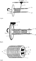
- FIG. 1 various possibilities of winding the fiber material are shown on the carriers.
- the carriers 1a, 1b are arranged displaceably.
- the carriers themselves, which in the present case are designed as rods, can be rotatable as individual rods or the device 2 with the rods can be made rotatable.
- the rods are formed substantially parallel to each other, while in the embodiment according to FIG. 1b the rod 1b is bent, so that the winding blank receives a corresponding shape.
- the carriers are usually formed substantially parallel.
- these rotatable rods may have a spiral surface that allows advancement of the winding blank.
- the wound fiber 3 is wound spirally around the carrier (bobbin).
- a helical winding is shown with a second counter-rotating helical winding, resulting in a multiple crossing of the fibers 3.
- the carriers 1a and 1b are arranged rotatably on the device 2.
- the fiber 3 is helically wound on the rotating carriers by the slidable rotor or fiberizer 4 to form the coil blank.
- the rotor 4 is movably arranged on a moving element to allow the different forms of winding for the winding blank.
- the winding can be helical, for example, with a slope of> 3% or substantially parallel.
- the winding can be formed in one or more layers, with multilayer training, the winding can also represent opposing helical windings, as well as in Figure 1C shown.
- FIG. 2b a similar device is shown.
- the thread take-up 4 is arranged on a disk 29 rotating around the device 2.
- the carriers 1a, 1b remain rigidly on the device 2.
- the carrier 1a and 1b can be designed as rotatable individual rods. They have here a spiral surface, which allow a feed of the winding blank.
- the device 5 for solidifying the winding blank is also shown.
- the device 5 makes it possible to permanently solidify the wound blank present on the supports 1a, 1b, eg by air swirling, sewing, concatenating, knotting, needling, felting or crocheting.
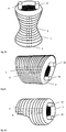
- FIG. 3 shows various molding materials.
- the FIG. 3a shows a hollow body which is present on four supports 1a, 1b, 1c, 1d. Also indicated are the solidification regions 6 of the solidified molding material 7.
- the solidified fiber material can then be further in desired shapes.
- the molding material can be brought into the desired structure.
- FIG. 3b an inventive shaped body 7 is shown, which has been wound on two curved beams 1a and 1b. In area 6, this shaped body was further solidified. As shown in the figure, the solidification of the winding blank can therefore take place only on one side of the winding. Alternatively, a solidification of both sides of the winding can take place, so that a flattened and compressed fiber mat is obtained.
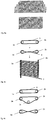
- FIG. 4b shows the individual process steps. In step 1, the fiber 3 is wound around the two beams 1a and 1b.
- this winding blank is further solidified in order to obtain a solidified molding material, in the form of a fiber mat in the present case.
- a solidified molding material in the form of a fiber mat in the present case.
- both sides of the coil were solidified together to obtain a flattened and consolidated mat.
- the lower illustration shows this fiber mat from a different perspective. To recognize are the bars 1a and 1b, the molding material 7 with the fibers 3 and the solidified areas. 6
- FIG. 4a Various types of cutting of the resulting molding material are shown.
- the upper diagram shows a cut executed at both ends at right angles; the middle figure shows a contours running obliquely on both sides.
- the Figure 4c shows the different possibilities of winding with two or three carriers to obtain the winding blank.
- the middle illustration shows a winding with three bars 1a, 1b, 1c.
- the lower diagram shows a further preferred embodiment, wherein the guide of the fiber 3 is crossing between the bars. This embodiment allows a solidification of the resulting molding material without additional measures.
Landscapes
- Engineering & Computer Science (AREA)
- Mechanical Engineering (AREA)
- Chemical & Material Sciences (AREA)
- Combustion & Propulsion (AREA)
- General Engineering & Computer Science (AREA)
- Textile Engineering (AREA)
- Exhaust Silencers (AREA)
- Nonwoven Fabrics (AREA)
- Moulding By Coating Moulds (AREA)
- Soundproofing, Sound Blocking, And Sound Damping (AREA)
- Yarns And Mechanical Finishing Of Yarns Or Ropes (AREA)
- Vehicle Interior And Exterior Ornaments, Soundproofing, And Insulation (AREA)
Applications Claiming Priority (2)
| Application Number | Priority Date | Filing Date | Title |
|---|---|---|---|
| DE201110012156 DE102011012156A1 (de) | 2011-02-23 | 2011-02-23 | Verfahren zur Herstellung eines Formmatrials aus Fasermaterialien und Vorrichtung hierüber |
| PCT/EP2012/053071 WO2012113866A1 (de) | 2011-02-23 | 2012-02-23 | Verfahren zur herstellung eines formmaterials aus fasermaterialien und vorrichtung hierfür |
Publications (2)
| Publication Number | Publication Date |
|---|---|
| EP2678535A1 EP2678535A1 (de) | 2014-01-01 |
| EP2678535B1 true EP2678535B1 (de) | 2018-06-27 |
Family
ID=45774190
Family Applications (1)
| Application Number | Title | Priority Date | Filing Date |
|---|---|---|---|
| EP12706542.3A Active EP2678535B1 (de) | 2011-02-23 | 2012-02-23 | Verfahren zur herstellung eines formmaterials aus fasermaterialien und vorrichtung hierfür |
Country Status (10)
| Country | Link |
|---|---|
| US (1) | US9133754B2 (enExample) |
| EP (1) | EP2678535B1 (enExample) |
| JP (3) | JP5931932B2 (enExample) |
| KR (1) | KR101857317B1 (enExample) |
| CN (1) | CN103492682B (enExample) |
| BR (1) | BR112013021531A2 (enExample) |
| DE (2) | DE102011012156A1 (enExample) |
| MX (1) | MX346370B (enExample) |
| RU (1) | RU2561360C2 (enExample) |
| WO (1) | WO2012113866A1 (enExample) |
Families Citing this family (5)
| Publication number | Priority date | Publication date | Assignee | Title |
|---|---|---|---|---|
| SI2602370T2 (sl) | 2011-12-07 | 2019-02-28 | So.La.Is Societa' Lavorazione Isolanti S.R.L. A Socio Unico | Postopek in naprava za proizvodnjo protihrupnega vložka za dušilec zvoka na izpušnem sistemu motorja z notranjim izgorevanjem |
| ITUA20161725A1 (it) * | 2016-03-16 | 2017-09-16 | So La Is Soc Lavorazione Isolanti S R L Con Unico Socio | Metodo per realizzare un materassino fibroso per isolare acusticamente e/o termicamente un componente di un veicolo a motore |
| EP3336326A1 (en) * | 2016-12-19 | 2018-06-20 | OCV Intellectual Capital, LLC | Systems for and methods of filling mufflers with fibrous material |
| DE102017117867A1 (de) | 2017-08-07 | 2019-02-07 | Dbw Holding Gmbh | Verfahren zur Herstellung von modifizierten Glasfasern und Filamenten daraus sowie Artikel diese enthaltend und ein Reinigungssystem |
| USD995825S1 (en) * | 2021-02-24 | 2023-08-15 | Nam Thanh Ho | Candle with crystal-shaped wax |
Citations (8)
| Publication number | Priority date | Publication date | Assignee | Title |
|---|---|---|---|---|
| US4495680A (en) * | 1982-02-17 | 1985-01-29 | Appleton Mills | Method and apparatus for forming a helical wound substrate composed solely of longitudinal yarns |
| WO1999023367A1 (en) * | 1997-11-04 | 1999-05-14 | Eurotex Thermal Engineering Ltd. | Sound muffling material and method of making thereof |
| US5926954A (en) * | 1997-09-10 | 1999-07-27 | Acoust-A-Fiber Research & Development, Inc. | Method of making a silencer |
| WO2000011327A1 (en) * | 1998-08-19 | 2000-03-02 | Lancaster Glass Fibre Ltd. | Silencer cartridge |
| US6241043B1 (en) * | 1998-05-01 | 2001-06-05 | Johannes Ulrich Goertz | Muffler insert and process for the production thereof |
| US6412596B1 (en) * | 2001-02-01 | 2002-07-02 | Owens Corning Composites Sprl | Process for filling a muffler and muffler filled with fibrous material |
| US6756107B1 (en) * | 1998-12-16 | 2004-06-29 | Asglawo Gmbh-Stoffe Zum Daemmen Und Verstaerken | Mounting mat for mounting an exhaust-gas catalytic converter |
| WO2006095373A1 (en) * | 2005-03-10 | 2006-09-14 | Vale S.R.L. | Small mattress-like glass fibre structure and method for its manufacture |
Family Cites Families (37)
| Publication number | Priority date | Publication date | Assignee | Title |
|---|---|---|---|---|
| GB413414A (en) * | 1933-02-22 | 1934-07-19 | Walter Fred Knebusch | Reel mechanism for simultaneously storing and delivering yarn or thread |
| US2700326A (en) * | 1949-07-29 | 1955-01-25 | Hawley Products Co | Method and apparatus for making accreted fibrous tubular bodies |
| CH409363A (de) * | 1960-11-15 | 1966-03-15 | Plast Anstalt | Verfahren und Einrichtung zur Herstellung durch Einlagen, vorzugsweise aus Faserstoffen, verstärkter, langgestreckter Kunststoff-, insbesondere Kunstharzkörper, die augenartig ausgebildete Teile aufweisen |
| AT256458B (de) * | 1961-08-25 | 1967-08-25 | Plast Anstalt | Verfahren zur Herstellung langgestreckter, Abschnitte augenartiger Ausbildung aufweisender Formkörper, insbesondere von Pleuelstangen |
| NL6512475A (enExample) * | 1965-09-27 | 1967-03-28 | ||
| DE1704768B1 (de) * | 1966-09-29 | 1971-08-26 | Shiro Kanao | Vorrichtung zum herstellen eines kunststoff wickelschlauches |
| FR2041851A5 (en) * | 1969-04-10 | 1971-02-05 | Delerue Dominique | Skein winder for dyeing shrinkable yarns |
| FR2256269B1 (enExample) * | 1973-12-28 | 1977-07-08 | Chevron Res | |
| DE2413315A1 (de) * | 1974-03-20 | 1975-10-02 | Didier Eng | Verfahren und anlage zur herstellung gekraeuselter faeden oder fadenbuendel aus thermoplastischem kunststoff |
| DE2530508C3 (de) * | 1975-04-08 | 1979-10-18 | Robreli Holding S.A., Luxemburg | Verfahren zur fortlaufenden Herstellung eines Garnkörpers |
| US4234054A (en) * | 1978-04-18 | 1980-11-18 | Chapin John S | Multi-duct muffler |
| JPS5620624A (en) * | 1979-07-24 | 1981-02-26 | Teijin Ltd | Composite three layered structure yarn having japanese brocade feeling |
| GB8312203D0 (en) * | 1983-05-04 | 1983-06-08 | Ford R A | Fibre structures |
| US5100047A (en) * | 1988-06-25 | 1992-03-31 | Yukihiro Nakagawa | Spacing ring for tubes in high temperature environment |
| JPH03257039A (ja) * | 1990-03-08 | 1991-11-15 | Honda Motor Co Ltd | ガラス繊維、ガラス繊維強化合成樹脂製品および内燃機関用排気系部品 |
| FR2659669B1 (fr) * | 1990-03-16 | 1992-06-12 | Rhone Poulenc Fibres | Fil a aspect file de fibres a base de polyamide. |
| SE468602B (sv) * | 1990-12-17 | 1993-02-15 | Albany Int Corp | Pressfilt samt saett att framstaella densamma |
| JPH06264711A (ja) * | 1993-03-15 | 1994-09-20 | Toyota Autom Loom Works Ltd | 耐熱性筒状フィルタ |
| JP3207608B2 (ja) * | 1993-04-19 | 2001-09-10 | 三恵技研工業株式会社 | 消音器の製造方法および製造装置 |
| JPH0719021A (ja) * | 1993-06-30 | 1995-01-20 | Sanritsu Kako Kk | 消音器、その製造方法および製造装置 |
| JP2967390B2 (ja) * | 1994-04-21 | 1999-10-25 | 本田技研工業株式会社 | 消音器及びその製造方法 |
| JP2719890B2 (ja) * | 1994-09-16 | 1998-02-25 | 株式会社ユタカ技研 | 消音器 |
| FR2739802B1 (fr) * | 1995-10-12 | 1998-01-02 | Cpl Composites Des Pays De Loi | Pieces de forme a section constante, en materiau composite et leur dispositif de fabrication a partir d'enroulements en echeveaux de fibres continues impregnees de resine thermodurcissable |
| RU2118416C1 (ru) * | 1997-07-22 | 1998-08-27 | Ключников Владимир Петрович | Нетканый волокнистый материал |
| JPH11324641A (ja) * | 1998-03-16 | 1999-11-26 | Nakagawa Sangyo Kk | 消音器用消音材とその製造方法 |
| ATE213793T1 (de) * | 1998-04-02 | 2002-03-15 | Heimbach Gmbh Thomas Josef | Textilbahn, verfahren zur herstellung einer solchen textilbahn sowie vorrichtung zur durchführung dieses verfahrens |
| US6196351B1 (en) | 1999-06-04 | 2001-03-06 | Lancaster Glass Fibre Limited | Silencer cartridge |
| DE60003201T2 (de) * | 2000-12-14 | 2003-12-18 | Nakagawa Sangyo Co., Ltd. | Schallschluckendes Material, Schalldämpfer mit diesem schallschluckenden Material, und Verfahren zur Formung einer schallschluckenden Schicht hierfür |
| US6491794B2 (en) * | 2001-03-29 | 2002-12-10 | Albany International Corp. | Base structure for seamed papermaker's fabrics |
| US7077922B2 (en) * | 2003-07-02 | 2006-07-18 | Owens Corning Composites S.P.R.L. | Technique to fill silencers |
| ITRM20050001A1 (it) | 2005-01-05 | 2006-07-06 | Eltech S R L | Sistema di guida di un raggio laser e di un raggio laser guida associato, e relativo dispositivo laser, in particolare per uso medicale chirurgico e terapeutico. |
| DE102005009045B4 (de) | 2005-01-20 | 2006-12-21 | Dbw Fiber Neuhaus Gmbh | Verfahren und Vorrichtung zum Einbringen von Dämmfasern in einen Schalldämpfer sowie Schalldämpfer mit eingebrachten Dämmfasern |
| JP4624190B2 (ja) * | 2005-06-20 | 2011-02-02 | トヨタ自動車株式会社 | バサルト繊維の製造方法 |
| ATE447095T1 (de) * | 2006-05-10 | 2009-11-15 | Metal Textiles Corp | Isolierhülse mit drahtgeflecht und drahtgewebe |
| DE202008005112U1 (de) * | 2008-04-12 | 2009-05-20 | Porextherm-Dämmstoffe Gmbh | Wärmedämmformkörper und damit ausgestattete Abgasreinigungsanlage |
| JP4973745B2 (ja) * | 2010-02-01 | 2012-07-11 | トヨタ自動車株式会社 | 連続繊維プリプレグの成形方法 |
| US8505203B2 (en) * | 2010-09-30 | 2013-08-13 | Tenneco Automotive Operating Company Inc. | Method of installing a longitudinally offset multi-layer mat in an exhaust gas aftertreatment or acoustic device |
-
2011
- 2011-02-23 DE DE201110012156 patent/DE102011012156A1/de not_active Ceased
-
2012
- 2012-02-23 DE DE201220012979 patent/DE202012012979U1/de not_active Expired - Lifetime
- 2012-02-23 KR KR1020137024975A patent/KR101857317B1/ko active Active
- 2012-02-23 EP EP12706542.3A patent/EP2678535B1/de active Active
- 2012-02-23 CN CN201280019868.5A patent/CN103492682B/zh active Active
- 2012-02-23 BR BR112013021531-3A patent/BR112013021531A2/pt not_active Application Discontinuation
- 2012-02-23 JP JP2013554893A patent/JP5931932B2/ja active Active
- 2012-02-23 MX MX2013009681A patent/MX346370B/es active IP Right Grant
- 2012-02-23 WO PCT/EP2012/053071 patent/WO2012113866A1/de not_active Ceased
- 2012-02-23 RU RU2013142829/06A patent/RU2561360C2/ru active
- 2012-02-23 US US14/001,186 patent/US9133754B2/en active Active
-
2016
- 2016-03-08 JP JP2016044449A patent/JP6239662B2/ja active Active
- 2016-07-05 JP JP2016133345A patent/JP2016196890A/ja active Pending
Patent Citations (8)
| Publication number | Priority date | Publication date | Assignee | Title |
|---|---|---|---|---|
| US4495680A (en) * | 1982-02-17 | 1985-01-29 | Appleton Mills | Method and apparatus for forming a helical wound substrate composed solely of longitudinal yarns |
| US5926954A (en) * | 1997-09-10 | 1999-07-27 | Acoust-A-Fiber Research & Development, Inc. | Method of making a silencer |
| WO1999023367A1 (en) * | 1997-11-04 | 1999-05-14 | Eurotex Thermal Engineering Ltd. | Sound muffling material and method of making thereof |
| US6241043B1 (en) * | 1998-05-01 | 2001-06-05 | Johannes Ulrich Goertz | Muffler insert and process for the production thereof |
| WO2000011327A1 (en) * | 1998-08-19 | 2000-03-02 | Lancaster Glass Fibre Ltd. | Silencer cartridge |
| US6756107B1 (en) * | 1998-12-16 | 2004-06-29 | Asglawo Gmbh-Stoffe Zum Daemmen Und Verstaerken | Mounting mat for mounting an exhaust-gas catalytic converter |
| US6412596B1 (en) * | 2001-02-01 | 2002-07-02 | Owens Corning Composites Sprl | Process for filling a muffler and muffler filled with fibrous material |
| WO2006095373A1 (en) * | 2005-03-10 | 2006-09-14 | Vale S.R.L. | Small mattress-like glass fibre structure and method for its manufacture |
Also Published As
| Publication number | Publication date |
|---|---|
| JP2016184161A (ja) | 2016-10-20 |
| KR101857317B1 (ko) | 2018-05-11 |
| RU2013142829A (ru) | 2015-03-27 |
| WO2012113866A1 (de) | 2012-08-30 |
| US20140054106A1 (en) | 2014-02-27 |
| JP2014511440A (ja) | 2014-05-15 |
| KR20140053863A (ko) | 2014-05-08 |
| JP6239662B2 (ja) | 2017-11-29 |
| JP2016196890A (ja) | 2016-11-24 |
| JP5931932B2 (ja) | 2016-06-08 |
| DE202012012979U1 (de) | 2014-06-02 |
| MX346370B (es) | 2017-03-16 |
| US9133754B2 (en) | 2015-09-15 |
| MX2013009681A (es) | 2014-03-05 |
| DE102011012156A1 (de) | 2012-08-23 |
| BR112013021531A2 (pt) | 2020-09-29 |
| RU2561360C2 (ru) | 2015-08-27 |
| CN103492682B (zh) | 2017-03-15 |
| CN103492682A (zh) | 2014-01-01 |
| EP2678535A1 (de) | 2014-01-01 |
Similar Documents
| Publication | Publication Date | Title |
|---|---|---|
| EP2678535B1 (de) | Verfahren zur herstellung eines formmaterials aus fasermaterialien und vorrichtung hierfür | |
| WO2012072405A1 (de) | Unidirektionale faserbänder aufweisender faservorformling aus verstärkungsfaserbündeln und verbundwerkstoff-bauteil | |
| DE102011080507A1 (de) | Bauteil aus einem Faserverbundwerkstoff | |
| EP2678534B1 (de) | Schalldämpfereinsatz für kraftfahrzeuge und verfahren zur herstellung hiervon | |
| EP0953736B1 (de) | Schalldämpfereinsatz und Verfahren zu dessen Herstellung | |
| DE102011077287A1 (de) | Faserverbundbauteil | |
| DE3806131C2 (enExample) | ||
| WO2008107060A1 (de) | Schalldämpfer-dämmelement, schalldämpfer sowie verfahren zur herstellung eines schalldämpfers | |
| WO2017186471A1 (de) | Verfahren zum herstellen eines flüssigkeitsbehälters, flüssigkeitsbehälter für ein kraftfahrzeug und struktur zur verringerung von schwappgeräuschen | |
| DE3205185A1 (de) | Verfahren zum herstellen einer schalldaempf-fuellung fuer einen auspufftopf sowie nach diesem verfahren hergestellte schalldaempf-fuellung | |
| DE102010012416A1 (de) | Bauteil und Formteil sowie Herstellungsverfahren hierfür | |
| EP2898196B1 (de) | Schalldämpfer und verfahren zu dessen herstellung | |
| WO2015144612A2 (de) | Faserverbundbauteil und verfahren zum herstellen eines faserverbundbauteils | |
| AT273771B (de) | Filterstöpsel für Tabakwaren, insbesondere für Zigaretten | |
| DE102010064446A1 (de) | Verfahren zum Herstellen eines textilen Halbzeugs, textiles Halbzeug, Verfahren zum Herstellen eines Faserverbundwerkstoffes und Faserverbundwerkstoff | |
| DE202012103599U1 (de) | Beutel zum Einsetzen in einen zur Schalldämpfungbestimmten Hohlraum eines Schalldämpfers | |
| DE102012018371A1 (de) | Beutel zum Einsetzen in einen zur Schalldämpfung bestimmten Hohlraum eines Schalldämpfers | |
| EP2990623B1 (de) | Schallabsorber | |
| DE102013101144A1 (de) | Verfahren zur Herstellung von Vliesstoffen aus Mineralfasern | |
| EP3124444A1 (de) | Endlosfaserformteil | |
| DE102015216253A1 (de) | Verfahren zur Herstellung einer Faserbandanordnung mit einer Mehrzahl von weitgehend parallel zueinander angeordneten Multifilamentgarnen |
Legal Events
| Date | Code | Title | Description |
|---|---|---|---|
| PUAI | Public reference made under article 153(3) epc to a published international application that has entered the european phase |
Free format text: ORIGINAL CODE: 0009012 |
|
| 17P | Request for examination filed |
Effective date: 20130923 |
|
| AK | Designated contracting states |
Kind code of ref document: A1 Designated state(s): AL AT BE BG CH CY CZ DE DK EE ES FI FR GB GR HR HU IE IS IT LI LT LU LV MC MK MT NL NO PL PT RO RS SE SI SK SM TR |
|
| DAX | Request for extension of the european patent (deleted) | ||
| 17Q | First examination report despatched |
Effective date: 20151221 |
|
| TPAC | Observations filed by third parties |
Free format text: ORIGINAL CODE: EPIDOSNTIPA |
|
| STAA | Information on the status of an ep patent application or granted ep patent |
Free format text: STATUS: EXAMINATION IS IN PROGRESS |
|
| RIC1 | Information provided on ipc code assigned before grant |
Ipc: D04H 3/015 20120101ALI20171110BHEP Ipc: B29C 53/60 20060101ALI20171110BHEP Ipc: B32B 37/14 20060101ALI20171110BHEP Ipc: B29C 65/56 20060101ALI20171110BHEP Ipc: D04H 5/08 20120101ALI20171110BHEP Ipc: D04H 3/004 20120101ALI20171110BHEP Ipc: D04H 1/4382 20120101ALI20171110BHEP Ipc: F01N 1/24 20060101AFI20171110BHEP Ipc: F01N 13/08 20100101ALI20171110BHEP Ipc: D04H 3/073 20120101ALI20171110BHEP Ipc: D04H 3/002 20120101ALI20171110BHEP Ipc: B29C 53/56 20060101ALI20171110BHEP |
|
| GRAP | Despatch of communication of intention to grant a patent |
Free format text: ORIGINAL CODE: EPIDOSNIGR1 |
|
| STAA | Information on the status of an ep patent application or granted ep patent |
Free format text: STATUS: GRANT OF PATENT IS INTENDED |
|
| INTG | Intention to grant announced |
Effective date: 20180115 |
|
| GRAS | Grant fee paid |
Free format text: ORIGINAL CODE: EPIDOSNIGR3 |
|
| GRAA | (expected) grant |
Free format text: ORIGINAL CODE: 0009210 |
|
| STAA | Information on the status of an ep patent application or granted ep patent |
Free format text: STATUS: THE PATENT HAS BEEN GRANTED |
|
| AK | Designated contracting states |
Kind code of ref document: B1 Designated state(s): AL AT BE BG CH CY CZ DE DK EE ES FI FR GB GR HR HU IE IS IT LI LT LU LV MC MK MT NL NO PL PT RO RS SE SI SK SM TR |
|
| REG | Reference to a national code |
Ref country code: GB Ref legal event code: FG4D Free format text: NOT ENGLISH |
|
| REG | Reference to a national code |
Ref country code: AT Ref legal event code: REF Ref document number: 1012547 Country of ref document: AT Kind code of ref document: T Effective date: 20180715 |
|
| REG | Reference to a national code |
Ref country code: IE Ref legal event code: FG4D Free format text: LANGUAGE OF EP DOCUMENT: GERMAN |
|
| REG | Reference to a national code |
Ref country code: DE Ref legal event code: R096 Ref document number: 502012012941 Country of ref document: DE |
|
| PG25 | Lapsed in a contracting state [announced via postgrant information from national office to epo] |
Ref country code: SE Free format text: LAPSE BECAUSE OF FAILURE TO SUBMIT A TRANSLATION OF THE DESCRIPTION OR TO PAY THE FEE WITHIN THE PRESCRIBED TIME-LIMIT Effective date: 20180627 Ref country code: BG Free format text: LAPSE BECAUSE OF FAILURE TO SUBMIT A TRANSLATION OF THE DESCRIPTION OR TO PAY THE FEE WITHIN THE PRESCRIBED TIME-LIMIT Effective date: 20180927 Ref country code: NO Free format text: LAPSE BECAUSE OF FAILURE TO SUBMIT A TRANSLATION OF THE DESCRIPTION OR TO PAY THE FEE WITHIN THE PRESCRIBED TIME-LIMIT Effective date: 20180927 Ref country code: FI Free format text: LAPSE BECAUSE OF FAILURE TO SUBMIT A TRANSLATION OF THE DESCRIPTION OR TO PAY THE FEE WITHIN THE PRESCRIBED TIME-LIMIT Effective date: 20180627 Ref country code: LT Free format text: LAPSE BECAUSE OF FAILURE TO SUBMIT A TRANSLATION OF THE DESCRIPTION OR TO PAY THE FEE WITHIN THE PRESCRIBED TIME-LIMIT Effective date: 20180627 |
|
| REG | Reference to a national code |
Ref country code: NL Ref legal event code: MP Effective date: 20180627 |
|
| REG | Reference to a national code |
Ref country code: LT Ref legal event code: MG4D |
|
| PG25 | Lapsed in a contracting state [announced via postgrant information from national office to epo] |
Ref country code: GR Free format text: LAPSE BECAUSE OF FAILURE TO SUBMIT A TRANSLATION OF THE DESCRIPTION OR TO PAY THE FEE WITHIN THE PRESCRIBED TIME-LIMIT Effective date: 20180928 Ref country code: HR Free format text: LAPSE BECAUSE OF FAILURE TO SUBMIT A TRANSLATION OF THE DESCRIPTION OR TO PAY THE FEE WITHIN THE PRESCRIBED TIME-LIMIT Effective date: 20180627 Ref country code: LV Free format text: LAPSE BECAUSE OF FAILURE TO SUBMIT A TRANSLATION OF THE DESCRIPTION OR TO PAY THE FEE WITHIN THE PRESCRIBED TIME-LIMIT Effective date: 20180627 Ref country code: RS Free format text: LAPSE BECAUSE OF FAILURE TO SUBMIT A TRANSLATION OF THE DESCRIPTION OR TO PAY THE FEE WITHIN THE PRESCRIBED TIME-LIMIT Effective date: 20180627 |
|
| PG25 | Lapsed in a contracting state [announced via postgrant information from national office to epo] |
Ref country code: NL Free format text: LAPSE BECAUSE OF FAILURE TO SUBMIT A TRANSLATION OF THE DESCRIPTION OR TO PAY THE FEE WITHIN THE PRESCRIBED TIME-LIMIT Effective date: 20180627 |
|
| PG25 | Lapsed in a contracting state [announced via postgrant information from national office to epo] |
Ref country code: RO Free format text: LAPSE BECAUSE OF FAILURE TO SUBMIT A TRANSLATION OF THE DESCRIPTION OR TO PAY THE FEE WITHIN THE PRESCRIBED TIME-LIMIT Effective date: 20180627 Ref country code: CZ Free format text: LAPSE BECAUSE OF FAILURE TO SUBMIT A TRANSLATION OF THE DESCRIPTION OR TO PAY THE FEE WITHIN THE PRESCRIBED TIME-LIMIT Effective date: 20180627 Ref country code: IS Free format text: LAPSE BECAUSE OF FAILURE TO SUBMIT A TRANSLATION OF THE DESCRIPTION OR TO PAY THE FEE WITHIN THE PRESCRIBED TIME-LIMIT Effective date: 20181027 Ref country code: EE Free format text: LAPSE BECAUSE OF FAILURE TO SUBMIT A TRANSLATION OF THE DESCRIPTION OR TO PAY THE FEE WITHIN THE PRESCRIBED TIME-LIMIT Effective date: 20180627 Ref country code: PL Free format text: LAPSE BECAUSE OF FAILURE TO SUBMIT A TRANSLATION OF THE DESCRIPTION OR TO PAY THE FEE WITHIN THE PRESCRIBED TIME-LIMIT Effective date: 20180627 Ref country code: SK Free format text: LAPSE BECAUSE OF FAILURE TO SUBMIT A TRANSLATION OF THE DESCRIPTION OR TO PAY THE FEE WITHIN THE PRESCRIBED TIME-LIMIT Effective date: 20180627 |
|
| PG25 | Lapsed in a contracting state [announced via postgrant information from national office to epo] |
Ref country code: IT Free format text: LAPSE BECAUSE OF FAILURE TO SUBMIT A TRANSLATION OF THE DESCRIPTION OR TO PAY THE FEE WITHIN THE PRESCRIBED TIME-LIMIT Effective date: 20180627 Ref country code: SM Free format text: LAPSE BECAUSE OF FAILURE TO SUBMIT A TRANSLATION OF THE DESCRIPTION OR TO PAY THE FEE WITHIN THE PRESCRIBED TIME-LIMIT Effective date: 20180627 Ref country code: ES Free format text: LAPSE BECAUSE OF FAILURE TO SUBMIT A TRANSLATION OF THE DESCRIPTION OR TO PAY THE FEE WITHIN THE PRESCRIBED TIME-LIMIT Effective date: 20180627 |
|
| REG | Reference to a national code |
Ref country code: DE Ref legal event code: R097 Ref document number: 502012012941 Country of ref document: DE |
|
| PLBE | No opposition filed within time limit |
Free format text: ORIGINAL CODE: 0009261 |
|
| STAA | Information on the status of an ep patent application or granted ep patent |
Free format text: STATUS: NO OPPOSITION FILED WITHIN TIME LIMIT |
|
| PG25 | Lapsed in a contracting state [announced via postgrant information from national office to epo] |
Ref country code: DK Free format text: LAPSE BECAUSE OF FAILURE TO SUBMIT A TRANSLATION OF THE DESCRIPTION OR TO PAY THE FEE WITHIN THE PRESCRIBED TIME-LIMIT Effective date: 20180627 |
|
| 26N | No opposition filed |
Effective date: 20190328 |
|
| PG25 | Lapsed in a contracting state [announced via postgrant information from national office to epo] |
Ref country code: SI Free format text: LAPSE BECAUSE OF FAILURE TO SUBMIT A TRANSLATION OF THE DESCRIPTION OR TO PAY THE FEE WITHIN THE PRESCRIBED TIME-LIMIT Effective date: 20180627 |
|
| REG | Reference to a national code |
Ref country code: CH Ref legal event code: PL |
|
| PG25 | Lapsed in a contracting state [announced via postgrant information from national office to epo] |
Ref country code: MC Free format text: LAPSE BECAUSE OF FAILURE TO SUBMIT A TRANSLATION OF THE DESCRIPTION OR TO PAY THE FEE WITHIN THE PRESCRIBED TIME-LIMIT Effective date: 20180627 Ref country code: LU Free format text: LAPSE BECAUSE OF NON-PAYMENT OF DUE FEES Effective date: 20190223 |
|
| REG | Reference to a national code |
Ref country code: BE Ref legal event code: MM Effective date: 20190228 |
|
| REG | Reference to a national code |
Ref country code: IE Ref legal event code: MM4A |
|
| PG25 | Lapsed in a contracting state [announced via postgrant information from national office to epo] |
Ref country code: AL Free format text: LAPSE BECAUSE OF FAILURE TO SUBMIT A TRANSLATION OF THE DESCRIPTION OR TO PAY THE FEE WITHIN THE PRESCRIBED TIME-LIMIT Effective date: 20180627 |
|
| PG25 | Lapsed in a contracting state [announced via postgrant information from national office to epo] |
Ref country code: CH Free format text: LAPSE BECAUSE OF NON-PAYMENT OF DUE FEES Effective date: 20190228 Ref country code: LI Free format text: LAPSE BECAUSE OF NON-PAYMENT OF DUE FEES Effective date: 20190228 |
|
| REG | Reference to a national code |
Ref country code: DE Ref legal event code: R082 Ref document number: 502012012941 Country of ref document: DE Representative=s name: MEISSNER BOLTE PATENTANWAELTE RECHTSANWAELTE P, DE Ref country code: DE Ref legal event code: R082 Ref document number: 502012012941 Country of ref document: DE Representative=s name: GRAMM, LINS & PARTNER PATENT- UND RECHTSANWAEL, DE Ref country code: DE Ref legal event code: R081 Ref document number: 502012012941 Country of ref document: DE Owner name: DBW ADVANCED FIBER TECHNOLOGIES GMBH, DE Free format text: FORMER OWNER: DBW HOLDING GMBH, 37120 BOVENDEN, DE |
|
| PG25 | Lapsed in a contracting state [announced via postgrant information from national office to epo] |
Ref country code: IE Free format text: LAPSE BECAUSE OF NON-PAYMENT OF DUE FEES Effective date: 20190223 |
|
| PG25 | Lapsed in a contracting state [announced via postgrant information from national office to epo] |
Ref country code: BE Free format text: LAPSE BECAUSE OF NON-PAYMENT OF DUE FEES Effective date: 20190228 |
|
| PG25 | Lapsed in a contracting state [announced via postgrant information from national office to epo] |
Ref country code: TR Free format text: LAPSE BECAUSE OF FAILURE TO SUBMIT A TRANSLATION OF THE DESCRIPTION OR TO PAY THE FEE WITHIN THE PRESCRIBED TIME-LIMIT Effective date: 20180627 |
|
| REG | Reference to a national code |
Ref country code: AT Ref legal event code: MM01 Ref document number: 1012547 Country of ref document: AT Kind code of ref document: T Effective date: 20190223 |
|
| PG25 | Lapsed in a contracting state [announced via postgrant information from national office to epo] |
Ref country code: AT Free format text: LAPSE BECAUSE OF NON-PAYMENT OF DUE FEES Effective date: 20190223 |
|
| PG25 | Lapsed in a contracting state [announced via postgrant information from national office to epo] |
Ref country code: MT Free format text: LAPSE BECAUSE OF FAILURE TO SUBMIT A TRANSLATION OF THE DESCRIPTION OR TO PAY THE FEE WITHIN THE PRESCRIBED TIME-LIMIT Effective date: 20180627 Ref country code: PT Free format text: LAPSE BECAUSE OF FAILURE TO SUBMIT A TRANSLATION OF THE DESCRIPTION OR TO PAY THE FEE WITHIN THE PRESCRIBED TIME-LIMIT Effective date: 20181029 |
|
| PG25 | Lapsed in a contracting state [announced via postgrant information from national office to epo] |
Ref country code: CY Free format text: LAPSE BECAUSE OF FAILURE TO SUBMIT A TRANSLATION OF THE DESCRIPTION OR TO PAY THE FEE WITHIN THE PRESCRIBED TIME-LIMIT Effective date: 20180627 |
|
| PG25 | Lapsed in a contracting state [announced via postgrant information from national office to epo] |
Ref country code: MK Free format text: LAPSE BECAUSE OF FAILURE TO SUBMIT A TRANSLATION OF THE DESCRIPTION OR TO PAY THE FEE WITHIN THE PRESCRIBED TIME-LIMIT Effective date: 20180627 |
|
| REG | Reference to a national code |
Ref country code: DE Ref legal event code: R082 Ref document number: 502012012941 Country of ref document: DE Representative=s name: MEISSNER BOLTE PATENTANWAELTE RECHTSANWAELTE P, DE |
|
| PGFP | Annual fee paid to national office [announced via postgrant information from national office to epo] |
Ref country code: HU Payment date: 20250218 Year of fee payment: 14 |
|
| PGFP | Annual fee paid to national office [announced via postgrant information from national office to epo] |
Ref country code: DE Payment date: 20250228 Year of fee payment: 14 |
|
| PGFP | Annual fee paid to national office [announced via postgrant information from national office to epo] |
Ref country code: FR Payment date: 20250221 Year of fee payment: 14 |
|
| PGFP | Annual fee paid to national office [announced via postgrant information from national office to epo] |
Ref country code: GB Payment date: 20250218 Year of fee payment: 14 |