EP2677211B1 - Speed change control device and control method for continuously variable transmission - Google Patents
Speed change control device and control method for continuously variable transmission Download PDFInfo
- Publication number
- EP2677211B1 EP2677211B1 EP11858893.8A EP11858893A EP2677211B1 EP 2677211 B1 EP2677211 B1 EP 2677211B1 EP 11858893 A EP11858893 A EP 11858893A EP 2677211 B1 EP2677211 B1 EP 2677211B1
- Authority
- EP
- European Patent Office
- Prior art keywords
- pulley
- thrust
- chain
- slip limit
- primary
- Prior art date
- Legal status (The legal status is an assumption and is not a legal conclusion. Google has not performed a legal analysis and makes no representation as to the accuracy of the status listed.)
- Not-in-force
Links
Images


Classifications
-
- F—MECHANICAL ENGINEERING; LIGHTING; HEATING; WEAPONS; BLASTING
- F16—ENGINEERING ELEMENTS AND UNITS; GENERAL MEASURES FOR PRODUCING AND MAINTAINING EFFECTIVE FUNCTIONING OF MACHINES OR INSTALLATIONS; THERMAL INSULATION IN GENERAL
- F16H—GEARING
- F16H61/00—Control functions within control units of change-speed- or reversing-gearings for conveying rotary motion ; Control of exclusively fluid gearing, friction gearing, gearings with endless flexible members or other particular types of gearing
- F16H61/66—Control functions within control units of change-speed- or reversing-gearings for conveying rotary motion ; Control of exclusively fluid gearing, friction gearing, gearings with endless flexible members or other particular types of gearing specially adapted for continuously variable gearings
- F16H61/662—Control functions within control units of change-speed- or reversing-gearings for conveying rotary motion ; Control of exclusively fluid gearing, friction gearing, gearings with endless flexible members or other particular types of gearing specially adapted for continuously variable gearings with endless flexible members
- F16H61/66272—Control functions within control units of change-speed- or reversing-gearings for conveying rotary motion ; Control of exclusively fluid gearing, friction gearing, gearings with endless flexible members or other particular types of gearing specially adapted for continuously variable gearings with endless flexible members characterised by means for controlling the torque transmitting capability of the gearing
-
- F—MECHANICAL ENGINEERING; LIGHTING; HEATING; WEAPONS; BLASTING
- F16—ENGINEERING ELEMENTS AND UNITS; GENERAL MEASURES FOR PRODUCING AND MAINTAINING EFFECTIVE FUNCTIONING OF MACHINES OR INSTALLATIONS; THERMAL INSULATION IN GENERAL
- F16H—GEARING
- F16H59/00—Control inputs to control units of change-speed-, or reversing-gearings for conveying rotary motion
- F16H59/68—Inputs being a function of gearing status
- F16H59/70—Inputs being a function of gearing status dependent on the ratio established
- F16H2059/704—Monitoring gear ratio in CVT's
-
- F—MECHANICAL ENGINEERING; LIGHTING; HEATING; WEAPONS; BLASTING
- F16—ENGINEERING ELEMENTS AND UNITS; GENERAL MEASURES FOR PRODUCING AND MAINTAINING EFFECTIVE FUNCTIONING OF MACHINES OR INSTALLATIONS; THERMAL INSULATION IN GENERAL
- F16H—GEARING
- F16H61/00—Control functions within control units of change-speed- or reversing-gearings for conveying rotary motion ; Control of exclusively fluid gearing, friction gearing, gearings with endless flexible members or other particular types of gearing
- F16H61/66—Control functions within control units of change-speed- or reversing-gearings for conveying rotary motion ; Control of exclusively fluid gearing, friction gearing, gearings with endless flexible members or other particular types of gearing specially adapted for continuously variable gearings
- F16H61/662—Control functions within control units of change-speed- or reversing-gearings for conveying rotary motion ; Control of exclusively fluid gearing, friction gearing, gearings with endless flexible members or other particular types of gearing specially adapted for continuously variable gearings with endless flexible members
- F16H61/66272—Control functions within control units of change-speed- or reversing-gearings for conveying rotary motion ; Control of exclusively fluid gearing, friction gearing, gearings with endless flexible members or other particular types of gearing specially adapted for continuously variable gearings with endless flexible members characterised by means for controlling the torque transmitting capability of the gearing
- F16H2061/66277—Control functions within control units of change-speed- or reversing-gearings for conveying rotary motion ; Control of exclusively fluid gearing, friction gearing, gearings with endless flexible members or other particular types of gearing specially adapted for continuously variable gearings with endless flexible members characterised by means for controlling the torque transmitting capability of the gearing by optimising the clamping force exerted on the endless flexible member
Definitions
- This invention relates to control of a pulley thrust of a continuously variable transmission using an endless torque transmission member such as a V-chain and a pair of pulleys.
- JP 2009-144751 A published by the Japan Patent Office in 2009, proposes that, in a continuously variable transmission (CVT) for a vehicle, in which an endless torque transmission member such as a V-chain is looped around a pair of pulleys including a primary pulley and a secondary pulley, a speed change response is enhanced by appropriately setting a rigidity of the pulleys.
- CVT continuously variable transmission
- Each of the primary pulley and the secondary pulley changes a width of a V-shaped groove in accordance with a pulley thrust applied in a direction of a rotation axis to change a winding radius of the V-chain. In this manner, a ratio between rotation speeds of the pulleys, that is, a speed ratio is changed.
- the pulley thrusts are obtained by a hydraulic pressure of a hydraulic pump using an internal combustion engine mounted in a vehicle as a power source.
- a predetermined thrust is required to be applied to the pulleys.
- the predetermined thrust is hereinafter referred to as a slip limit thrust.
- the slip limit thrust is a value common to the primary pulley and the secondary pulley, and is determined depending on the winding radius of the V-chain around the primary pulley.
- the slip limit thrust is calculated by the following Expression (1).
- the sheave angle ⁇ is a constant that is determined in advance by shapes and sizes of the primary pulley, the secondary pulley, and the V-chain.
- the friction coefficient ⁇ is a constant, which is determined in advance by materials of the primary pulley, the secondary pulley, and the V-chain.
- the pulley thrusts are controlled based on the slip limit thrust that is calculated without taking the stretch of the V-chain into consideration, the pulley thrusts become excessively large in the case where the V-chain stretches. As a result, a loss in hydraulic pressure or a friction loss increases, which leads to an increase in fuel consumption of the internal combustion engine, which drives the hydraulic pump.
- a speed ratio control device is applied to a continuously variable transmission comprising an endless torque transmission member looped around a pair of pulleys.
- One of the pulleys has a movable sheave configured to displace in an axial direction in accordance with an applied pulley thrust to change a winding radius of the endless torque transmission member.
- the speed ratio control device comprises a sensor that detects an operating state of the continuously variable transmission and a programmable controller.
- the programmable controller is programmed to calculate a stretch amount of the endless torque transmission member based on the operating state of the continuously variable transmission, and a slip limit thrust in accordance with the stretch amount, and control the pulley thrust of the one of pulleys based on the slip limit thrust.
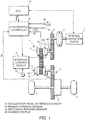
- a vehicle driving system comprises an internal combustion engine 1 as a running power source. Rotation of the internal combustion engine 1 is output to drive wheels 7 via a torque converter 2, a first gear train 3, a continuously variable transmission (hereinafter referred to as "CVT") 4, a second gear train 5, and a final reduction gear 6.
- CVT continuously variable transmission
- the CVT 4 is constituted by a chain-type continuously variable transmission mechanism.
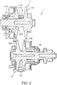
- the CVT 4 comprises a primary pulley 11, a secondary pulley 12, and a V-chain 13 as an endless torque transmission member looped around the pulleys 11 and 12.
- the V-chain 13 has a V-shaped cross section having a width gradually decreasing toward the center of the V-chain 13.
- the primary pulley 11 of the CVT 4 includes a fixed sheave 11A and a movable sheave 11B.
- the fixed sheave 11A includes a pulley shaft 11C.
- the movable sheave 11B is supported on an outer circumference of the pulley shaft 11C so as to be slidable in an axial direction.
- the movable sheave 11B changes a distance from the fixed sheave 11A on the pulley shaft 11C by a pulley thrust applied by a hydraulic cylinder 15 in the axial direction, thereby changing a winding radius of the V-chain 13.
- the secondary pulley 12 includes a fixed sheave 12A and a movable sheave 12B.
- the fixed sheave 12A includes a pulley shaft 12C.
- the movable sheave 12B is supported on an outer circumference of the pulley shaft 12C so as to be slidable in the axial direction.
- the movable sheave 12B changes a distance from the fixed sheave 12A on the pulley shaft 12C by a pulley thrust applied by a hydraulic cylinder 16 in the axial direction, thereby changing a winding radius of the V-chain 13.
- the CVT 4 changes the winding radii of the V-chain 13 around the primary pulley 11 and the secondary pulley 12 in the above-mentioned manner to continuously change a speed ratio.
- the "speed ratio" is a value obtained by dividing an input rotation speed of the CVT 4 by an output rotation speed of the CVT 4.
- the primary pulley 11 is provided with pulley stoppers 21A and 21B.
- a portion of the movable sheave 11B that comes into abutment against the V-chain 13 is referred to as a "distal end", whereas an end portion on the opposite side is referred to as a "rear end”.
- the pulley stopper 21A is provided inside the hydraulic cylinder 15 and comes into abutment against the rear end of the movable sheave 11B so as to limit a displacement of the movable sheave 11B away from the fixed sheave 11A.
- the pulley stopper 21B is formed in a step-like shape on the outer circumference of the pulley shaft 12C of the fixed sheave 11A.
- a corresponding step is formed on an inner circumference of the movable sheave 11B.
- the step of the movable sheave 11B comes into abutment against the pulley stopper 12B, which limits a displacement of the movable sheave 11B towards the fixed sheave 11A.
- the pulley stoppers 21A and 21B may be provided to the secondary pulley 12.
- the pulley stoppers 21A and 21B have the following functions. Specifically,
- the function (1) is required in the vicinity of a maximum speed ratio in the case of the primary pulley 11 and in the vicinity of a minimum speed ratio in the case of the secondary pulley 12.
- the function (2) is required in the vicinity of the minimum speed ratio in the case of the primary pulley 11 and in the vicinity of the maximum speed ratio in the case of the secondary pulley 12.
- the rear end of the movable sheave 11B comes into abutment against the pulley stopper 21A to define a minimum value of the winding radius of the V-chain 13 around the primary pulley 11.
- the position of the pulley stopper 21A is set so that a width of a portion having the shortest groove width formed by the fixed sheave 11A and the movable sheave 11B becomes smaller than a width of an inner circumference of the V-chain 13 in a state in which the rear end of the movable sheave 11B abuts against the pulley stopper 21A, thereby preventing the V-chain 13 from coming into contact with the pulley shaft 11C.
- the step formed on the inner circumference of the movable sheave 12B comes into abutment against the step-like pulley stopper 21B formed on the outer circumference of the pulley shaft 11C to define a maximum value of the winding radius of the V-chain 13 around the primary pulley 11.
- the radius of a sheave surface is designed in advance in consideration of the stretch of the V-chain 13 so that the V-chain 13 does not come off from the groove formed by the fixed sheave 11A and the movable sheave 11B even if the V-chain 13 stretches.
- the rear end of the movable sheave 12B comes into abutment against the pulley stopper 21A to define a minimum value of the winding radius of the V-chain 13 around the secondary pulley 12.
- the position of the pulley stopper 21A is set so that a width of a portion having the shortest groove width formed by the fixed sheave 12A and the movable sheave 12B becomes smaller than a width of the inner circumference of the V-chain 13 in a state in which the rear end of the movable sheave 12B abuts against the pulley stopper 21A, thereby preventing the V-chain 13 from coming into contact with the pulley shaft 12C.
- the step formed on the inner circumference of the movable sheave 12B comes into abutment against the step-like pulley stopper 21B formed on the outer circumference of the pulley shaft 11C to define a maximum value of the winding radius of the V-chain 13 around the primary pulley 12.
- the radius of a sheave surface is designed in advance in consideration of the stretch of the V-chain 13 so that the V-chain 13 does not come off from the groove formed by the fixed sheave 12A and the movable sheave 12B even if the V-chain 13 stretches.
- the pulley stoppers 21A and 21B may be provided to any one of the primary pulley 11 and the secondary pulley 12. In this embodiment, the pulley stoppers 21A and 21B are provided to the primary pulley 11, whereas a pulley stopper is not provided to the secondary pulley 12.
- the transmission control of the CVT 4 is performed by a hydraulic pump 10 driven by using a part of power of the internal combustion engine 1, a hydraulic control circuit 21 for supplying hydraulic pressures to the hydraulic cylinders 15 and 16 of the continuously variable transmission 4 after regulating a hydraulic pressure from the hydraulic pump 10, and a transmission controller 22 for controlling the hydraulic control circuit 21.
- the transmission controller 22 is constituted by a microcomputer including a central processing unit (CPU), a read-only memory (ROM), a random-access memory (RAM), and an input/output interface (I/O interface).
- the controller may be constituted by a plurality of microcomputers.
- detection data is input as signals from an accelerator-pedal depression sensor 41 for detecting an opening degree APO of an accelerator pedal provided to the vehicle as a load of the internal combustion engine 1, an inhibitor switch 45 for detecting a selected position of a selector lever provided to the vehicle, a primary rotation sensor 42 for detecting a rotation speed Np of the primary pulley 11, and a secondary rotation sensor 43 for detecting a rotation speed Ns of the secondary pulley 12.
- the routine is repeatedly executed at constant intervals of, for example, ten milliseconds, during the rotation of the primary pulley 11.
- the transmission controller 22 calculates a target speed ratio Dip by a known method based on the load of the internal combustion engine 1 and a vehicle speed VSP.
- the accelerator-pedal opening degree APO detected by the accelerator-pedal depression sensor 41 is used as the load of the internal combustion engine 1.
- the vehicle speed VSP is calculated from the rotation speed Ns of the secondary pulley 12 and a gear ratio of the second gear train 5 and the final reduction gear 6.
- a pulley thrust Fp for the primary pulley 11 and a pulley thrust Fs for the secondary pulley 12 are calculated.
- a step S3 the transmission controller 22 calculates a slip limit thrust Fmin. This processing is subsequently described in detail.
- the movable sheave 11B changes the distance from the fixed sheave 11A on the pulley shaft 11C by the pulley thrust applied by the hydraulic cylinder 15 to the movable sheave 11B, thereby changing a winding radius Rp of the V-chain 13.
- the movable sheave 12B changes the distance from the fixed sheave 12A on the pulley shaft 12C by the pulley thrust applied by the hydraulic cylinder 16 to the movable sheave 12B, thereby changing a winding radius Rs of the V-chain 13.
- the hydraulic pressures of the hydraulic cylinders 15 and 16, which apply the pulley thrusts to the pulleys 11 and 12, may be increased.
- a discharge pressure of the hydraulic pump 10 for supplying the hydraulic pressures to the hydraulic cylinders 15 and 16 is required to be increased.
- a loss in hydraulic pressure or a friction loss in a hydraulic-pressure supply system increases, which leads to an increase in fuel consumption of the internal combustion engine 1 which drives the hydraulic pump 10.
- the transmission controller 22 calculates a minimum value of the pulley thrust, which does not cause the substantial slip of the V-chain 13 with respect to the actual speed ratio ip, as the slip limit thrust Fmin.
- the slip limit thrust Fmin is a value common to the primary pulley 11 and the secondary pulley 12.
- the transmission controller 22 minimizes energy consumption caused by a transmission operation of the CVT 4 by calculating the slip limit thrust Fmin in consideration of the stretch of the V-chain 13.
- a thrust equal to or greater than the slip limit thrust is required to be applied to each of the pulleys.
- the winding radius Rp of the V-chain 13 around the primary pulley 11 can be geometrically calculated with respect to the actual speed ratio ip. Therefore, if the stretch of the V-chain 13 is not taken into consideration, the slip limit thrust Fmin can be directly calculated by Expression (1) using the value of the winding radius.
- the pulley thrust Fs for the secondary pulley 12 is set by using the slip limit thrust Fmin calculated without taking the stretch of the V-chain 13 into consideration, the pulley thrust Fs becomes excessively large. As a result, a loss in hydraulic pressure or a friction loss increases, which leads to an increase in fuel consumption of the internal combustion engine 1 that drives the hydraulic pump 10.
- the slip limit thrust Fmin is calculated in consideration of the stretch of the V-chain 13.
- the winding radius Rp of the V-chain 13 around the primary pulley 11 increases.
- the slip limit thrust Fmin decreases.
- the decrease of the slip limit thrust Fmin lowers a tension of the V-chain 13. Consequently, a stretch amount of the V-chain 13 is decreased.
- the slip limit thrust Fmin cannot be calculated without a convergence calculation.
- the transmission controller 22 performs the convergence calculation of the slip limit thrust Fmin by a calculation logic illustrated in FIG. 4 .
- the transmission controller 22 comprises a chain-tension calculating unit B11, a chain-length calculating unit B12, a primary-pulley winding radius-calculating unit B13, and a slip-limit-thrust calculating unit B14. All of the blocks shown in FIG. 4 are virtual units illustrating the function of the transmission controller 22 for calculating the slip limit thrust Fmin, and do not exist as physical entities.]
- an input torque Tp to the primary pulley 11, the actual speed ratio ip, the rotation speed Np of the primary pulley 11, and the slip limit thrust Fmin are input.
- the input torque Tp to the primary torque 11 is calculated by a known method, for example, disclosed in JP 08-200461 A and JP 2002-106705 A , based on an engine torque Teng input from an engine control unit (ECU) 51 illustrated in FIG. 1 , a lock-up state of the torque converter 2, and an inertia torque of power transmission members from the internal combustion engine 1 to the primary pulley 11.
- ECU engine control unit
- the rotation speed Np of the primary pulley 11 is a value detected by the primary rotation sensor 42.
- the actual speed ratio ip is calculated as a ratio of the rotation speed Np of the primary pulley 11, which is detected by the primary rotation sensor 42, and the rotation speed Ns of the secondary pulley 12, which is detected by the secondary rotation sensor 43.
- the slip limit thrust Fmin is a value calculated by the slip-limit-thrust calculating unit B14.
- the transmission controller 22 performs the convergence calculation by inputting the slip limit thrust Fmin calculated by the slip-limit-thrust calculating unit B14 to the chain-tension calculating unit B11 again.
- An initial value of the slip limit thrust Fmin is set, for example, as follows. Specifically, a winding radius Rp0 around the primary pulley 11 is calculated from a chain length L0 without stretch and the speed ratio of the primary pulley 11 and the secondary pulley 12. Then, a slip limit thrust calculated from the winding radius Rp0 and the input torque Tp to the primary pulley 11 is used as an initial value of the slip limit thrust Fmin.
- the initial value of the slip limit thrust Fmin can also be set by another method.
- the chain-tension calculating unit B11 calculates a chain tension Tn from the input torque Tp to the primary pulley 11, the slip limit thrust Fmin, the pulley thrust Fp for the primary pulley 11, the rotation speed Np of the primary pulley 11, and the actual speed ratio ip.
- the chain tension Tn of the V-chain 13 has a characteristic of gently increasing as the input torque Tp of the primary pulley 11 increases when the actual speed ratio ip of the primary pulley 11 and the secondary pulley 12, the pulley thrust for the secondary pulley 12, and the rotation speed Np of the primary pulley 11 are constant.
- the thrust Fs for the secondary pulley 12 and the thrust Fp for the primary pulley 11 have a constant relationship based on the actual speed ratio ip.
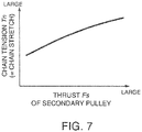
- the chain tension Tn of the V-chain 13 increases as the pulley thrust Fs for the secondary pulley 12 increases, when the input torque Tp to the primary pulley 11, the rotation speed Np thereof, and the actual speed ratio ip of the primary pulley 11 and the secondary pulley 12 are constant.
- the chain tension Tn of the V-chain 13 increases as the rotation speed Np of the primary pulley 11 becomes higher, when the input torque Tp to the primary pulley 11, the pulley thrust Fs for the secondary pulley 12, and the actual speed ratio ip are constant.
- the chain tension Tn of the V-chain 13 tends to slightly decrease as the actual speed ratio ip of the primary pulley 11 and the secondary pulley 12 increases, when the pulley thrust Fs for the secondary pulley 12, the input torque to the primary pulley 11, and the rotation speed Np of the primary pulley 11 are constant.
- a four-dimensional map of the chain tension Tn which has the input torque Tp to the primary pulley 11, the pulley thrust Fs for the secondary pulley 12, the actual speed ratio ip, and the rotation speed Np of the primary pulley 11 as parameters indicating an operating state of the CVT 4, can be created.
- the thus created four-dimensional map of the chain tension Tn is stored in advance.
- the chain-tension calculating unit B11 obtains the chain tension Tn based on the input data by referring to the four-dimensional map of the chain tension Tn stored in the ROM.
- the chain-length calculating unit B12 obtains a chain stretch amount from the chain tension Tn and then adds the chain stretch amount to the chain length without stretch to calculate a chain length L .
- the relationship between the chain tension Tn and the chain stretch amount is determined experimentally in advance.
- the chain length without stretch is a known value.
- the primary-pulley winding radius calculating unit B13 calculates the winding radius Rp of the V-chain 13 around the primary pulley 11 (hereinafter referred to as "primary-pulley winding radius Rp ”) from the chain length L , a distance dis between the pulley shafts, and the actual speed ratio ip.
- the distance dis between the pulley shafts is a fixed value indicating a distance between the rotation axis of the primary pulley 11 and the rotation axis of the secondary pulley 12.
- the primary-pulley winding radius calculating unit B13 calculates the primary-pulley winding radius Rp by a geometrical calculation.
- a map of the primary-pulley winding radius Rp which has the chain length L and the actual speed ratio ip as parameters, is stored in advance in the ROM of the transmission controller 22. A search is made through the map using the chain length L and the target speed ratio Dip to calculate the primary-pulley winding radius Rp.
- the primary-pulley winding radius Rp in the vicinity of the maximum speed ratio does not become smaller than a minimum value corresponding to the position of the pulley stopper 21A.
- the primary-pulley winding radius calculating unit B13 corrects the primary-pulley winding radius Rp to the minimum value.
- the primary-pulley winding radius calculating unit B13 prevents the winding radius Rp around the primary pulley 11 from becoming smaller than the minimum value in terms of prevention of the value of the slip limit thrust Fmin from being calculated to be excessively large.
- the winding radius Rp around the primary pulley 11 in the vicinity of the minimum speed ratio does not become greater than a maximum value corresponding to the position of the pulley stopper 21B.
- the primary-pulley winding radius calculating unit B13 corrects the winding radius Rp around the primary pulley 11 to the maximum value.
- the primary-pulley winding radius calculating unit B13 restrict the primary-pulley winding radius Rp to the maximum value or smaller in terms of prevention of the value of the slip limit thrust Fmin from being calculated to be excessively small.
- the limitation of the winding radius Rp around the primary pulley 11 to the minimum value and the maximum value can also be realized by limiting a map value of the map of the primary-pulley winding radius Rp in advance.
- the slip-limit-thrust calculating unit B14 calculates the slip limit thrust Fmin by using Expression (1) based on the input torque Tp to the primary pulley 11, the primary-pulley winding radius Rp calculated by the primary-pulley winding radius calculating unit B13, and a friction coefficient ⁇ and a sheave angle ⁇ , which are fixed values.
- the slip limit thrust Fmin calculated by the slip-limit-thrust calculating unit B14 is input again to the chain-tension calculating unit B11 so that the chain tension Tn is recalculated. Further, the chain length L , the primary-pulley winding radius Rp , and the slip limit thrust Fmin are respectively recalculated in the chain-length calculating unit B12, the primary-pulley winding radius calculating unit B13, and the slip-limit-thrust calculating unit B14.
- the transmission controller 22 repeats the processing of the blocks B11 to B14 to perform the convergence calculation. As a result of the convergence calculation, the slip limit thrust Fmin corresponding to the actual speed ratio ip is obtained.
- the transmission controller 22 imposes a limitation with the slip limit thrust Fmin to the pulley thrust Fp for the primary pulley 11 and the pulley thrust Fs for the secondary pulley 12, which are calculated in the step S2. Further, the hydraulic pressures to be supplied to the hydraulic cylinders 15 and 16, which correspond to the limited value, are instructed to the hydraulic control circuit 21.
- the slip limit thrust Fmin calculated by Expression (1) increases as indicated by a solid line in FIG. 10D .
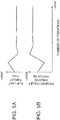
- the chain tension Tn of the v-chain 13 also increases as illustrated in FIG. 6 .
- the increase in the chain tension Tn increases the chain length L as illustrated in FIG. 10C .
- the primary-pulley winding radius Rp also increases.
- the increase in the primary-pulley winding radius Rp brings about a decrease in the slip limit thrust Fmin, as expressed by Expression (1).
- the slip limit thrust Fmin maintains a constant value, as indicated by the solid line in FIG. 10D .
- the chain tension Tn of the V-chain 13 also increases as illustrated in FIG. 8 .
- the increase in the chain tension Tn further increases the chain length L , as illustrated in FIG. 10C .
- the further increase in the chain length L further increases the primary-pulley winding radius Rp .
- the further increase in the primary-pulley winding radius Rp brings about a further decrease in the slip limit thrust Fmin, as expressed by Expression (1).
- the slip limit thrust Fmin maintains a constant value also after time t2 , as indicated by the solid line in FIG. 10D .
- the pulley thrust Fs for the secondary pulley 12 is set equal to the slip limit thrust Fmin. Based on the pulley thrust, the thrust Fp of the primary pulley 11 is calculated. After time t1, the slip limit thrust Fmin calculated in consideration of the stretch of the V-chain 13 is smaller than the slip limit thrust Fmin calculated without taking the stretch of the V-chain into consideration. Therefore, the thrust F s of the secondary pulley determined based on the slip limit thrust Fmin is a value in consideration of the stretch of the V-chain 13 and is reduced to be smaller than that in the case where the stretch of the V-chain 13 is not taken into consideration.
- the hydraulic pressure supplied to the hydraulic cylinder 16, which applies the pulley thrust to the secondary pulley 12, can be reduced.
- the primary thrust Fp calculated based on the secondary thrust Fs is also reduced to be smaller than that in the case where the stretch of the V-chain 13 is not taken into consideration. Therefore, the hydraulic pressure supplied to the hydraulic cylinder 15, which applies the pulley thrust to the primary pulley 11, can also be reduced. As a result, the loss in hydraulic pressure or the friction loss caused by the supply of the hydraulic pressures becomes small. Thus, the fuel consumption of the internal combustion engine 1 which drives the hydraulic pump 10 can be reduced.
- FIGS. 10A to 10D for convenience of the description, the input torque Tp to the primary pulley 11 and the rotation speed Np of the primary pulley 11 are depicted as increasing in a stepwise manner. In practice, however, the above-mentioned values do not increase instantaneously but increase within a certain time frame.
- the chain length L is calculated from the parameters indicating the operating state of the CVT 4, and the primary-pulley winding radius Rp is calculated from the chain length L .
- a map which defines the relationship between the parameters indicating the operating state of the CVT 4 and the primary-pulley winding radius Rp can be stored in the ROM of the transmission controller 22 so that the primary-pulley winding radius Rp is directly calculated from the parameters.
- the transmission controller 22 performs the convergence calculation by iterating the process of calculating the chain length L again by using the decreased slip limit thrust Fmin and further calculating the slip limit thrust Fmin based on a new chain length L .
- a primary-pulley winding radius R' can be calculated in advance for the combination of the input torque Tp to the primary pulley 11, the actual speed ratio ip, and the rotation speed Np of the primary pulley 11 by the iterative calculation illustrated in FIG. 4 so that the result of calculation is stored as a map in the ROM of the transmission controller 22.
- the chain-tension calculating unit B11, the chain-length calculating unit B12, and the primary-pulley winding radius calculating unit B13 of the transmission controller 22 illustrated in FIG. 4 can be replaced by a single primary-pulley winding radius calculating unit B21 as illustrated in FIG. 12 .
- the slip-limit-thrust calculating unit B14 uses the primary-pulley winding radius R' and the input torque Tp to the primary pulley 11 searched from the map as in the case of FIG. 4 to calculate the slip limit thrust Fmin.
- the convergence calculation can be omitted. Therefore, the computation load of the transmission controller 22 can be reduced.
- the transmission controller 22 restricts the pulley thrust Fp for the primary pulley 11 with the slip limit thrust Fmin.
- the slip limit thrust Fmin decreases.
Landscapes
- Engineering & Computer Science (AREA)
- General Engineering & Computer Science (AREA)
- Mechanical Engineering (AREA)
- Control Of Transmission Device (AREA)
Applications Claiming Priority (2)
| Application Number | Priority Date | Filing Date | Title |
|---|---|---|---|
| JP2011030066A JP5691602B2 (ja) | 2011-02-15 | 2011-02-15 | 無段変速機の変速制御装置及び制御方法 |
| PCT/JP2011/077899 WO2012111216A1 (ja) | 2011-02-15 | 2011-12-02 | 無段変速機の変速制御装置及び制御方法 |
Publications (3)
| Publication Number | Publication Date |
|---|---|
| EP2677211A1 EP2677211A1 (en) | 2013-12-25 |
| EP2677211A4 EP2677211A4 (en) | 2018-04-18 |
| EP2677211B1 true EP2677211B1 (en) | 2018-10-24 |
Family
ID=46672166
Family Applications (1)
| Application Number | Title | Priority Date | Filing Date |
|---|---|---|---|
| EP11858893.8A Not-in-force EP2677211B1 (en) | 2011-02-15 | 2011-12-02 | Speed change control device and control method for continuously variable transmission |
Country Status (8)
| Country | Link |
|---|---|
| US (1) | US8903615B2 (es) |
| EP (1) | EP2677211B1 (es) |
| JP (1) | JP5691602B2 (es) |
| CN (1) | CN103339416B (es) |
| BR (1) | BR112013020882A2 (es) |
| MX (1) | MX2013008983A (es) |
| RU (1) | RU2551407C2 (es) |
| WO (1) | WO2012111216A1 (es) |
Families Citing this family (8)
| Publication number | Priority date | Publication date | Assignee | Title |
|---|---|---|---|---|
| JP2012149659A (ja) * | 2011-01-17 | 2012-08-09 | Nissan Motor Co Ltd | 無段変速機の変速制御装置及び制御方法 |
| CN105346665B (zh) * | 2014-08-18 | 2019-08-02 | 韩培洲 | 带有直接档传动和皮带无极变速传动的变速系统 |
| EP3276216B1 (en) * | 2015-03-23 | 2019-01-02 | JATCO Ltd | Vehicle and vehicle control method |
| JP2018003952A (ja) * | 2016-07-01 | 2018-01-11 | 本田技研工業株式会社 | ベルト式無段変速機 |
| JP6414151B2 (ja) * | 2016-07-07 | 2018-10-31 | トヨタ自動車株式会社 | ベルト式無段変速機の制御装置 |
| CN108223779B (zh) * | 2017-06-28 | 2019-09-06 | 长城汽车股份有限公司 | 变速器最高挡速比的确定方法和装置 |
| CN109185445B (zh) * | 2017-06-30 | 2020-02-07 | 上海汽车集团股份有限公司 | 一种速比的计算方法、装置及无级变速控制器 |
| JP7132790B2 (ja) * | 2018-08-09 | 2022-09-07 | ジヤトコ株式会社 | 無段変速機及び無段変速機の制御方法 |
Family Cites Families (12)
| Publication number | Priority date | Publication date | Assignee | Title |
|---|---|---|---|---|
| JP2656501B2 (ja) * | 1987-08-28 | 1997-09-24 | アイシン・エィ・ダブリュ株式会社 | ベルト式無段変速装置 |
| JP3422227B2 (ja) * | 1997-07-16 | 2003-06-30 | 日産自動車株式会社 | 無段変速機の制御装置 |
| EP0931959B1 (en) * | 1998-01-21 | 2001-11-07 | Van Doorne's Transmissie B.V. | Continuously variable transmission |
| DE69925283T2 (de) * | 1999-12-20 | 2006-01-19 | Van Doorne's Transmissie B.V. | Treibriemen für ein stufenlos regelbares Getriebe, endloses Band dafür und Herstellungsverfahren solch eines Bandes |
| JP2004076906A (ja) * | 2002-08-21 | 2004-03-11 | Toyota Motor Corp | ベルト式無段変速機の制御装置 |
| US7261672B2 (en) * | 2003-03-19 | 2007-08-28 | The Regents Of The University Of California | Method and system for controlling rate of change of ratio in a continuously variable transmission |
| JP4167929B2 (ja) * | 2003-04-24 | 2008-10-22 | ジヤトコ株式会社 | ベルト式無段変速機の変速制御装置 |
| JP2006189079A (ja) * | 2005-01-05 | 2006-07-20 | Fuji Heavy Ind Ltd | 無段変速機の変速制御装置 |
| JP2009144751A (ja) | 2007-12-11 | 2009-07-02 | Jtekt Corp | 無段変速機 |
| JP5347539B2 (ja) * | 2008-03-26 | 2013-11-20 | 日産自動車株式会社 | 無段変速装置 |
| JP4923080B2 (ja) * | 2009-03-27 | 2012-04-25 | ジヤトコ株式会社 | 無段変速機及びその制御方法 |
| JP2012149659A (ja) * | 2011-01-17 | 2012-08-09 | Nissan Motor Co Ltd | 無段変速機の変速制御装置及び制御方法 |
-
2011
- 2011-02-15 JP JP2011030066A patent/JP5691602B2/ja not_active Expired - Fee Related
- 2011-12-02 WO PCT/JP2011/077899 patent/WO2012111216A1/ja active Application Filing
- 2011-12-02 US US13/984,932 patent/US8903615B2/en not_active Expired - Fee Related
- 2011-12-02 RU RU2013142149/11A patent/RU2551407C2/ru not_active IP Right Cessation
- 2011-12-02 MX MX2013008983A patent/MX2013008983A/es active IP Right Grant
- 2011-12-02 BR BR112013020882A patent/BR112013020882A2/pt active Search and Examination
- 2011-12-02 EP EP11858893.8A patent/EP2677211B1/en not_active Not-in-force
- 2011-12-02 CN CN201180066835.1A patent/CN103339416B/zh not_active Expired - Fee Related
Non-Patent Citations (1)
| Title |
|---|
| None * |
Also Published As
| Publication number | Publication date |
|---|---|
| BR112013020882A2 (pt) | 2016-09-27 |
| EP2677211A1 (en) | 2013-12-25 |
| JP5691602B2 (ja) | 2015-04-01 |
| CN103339416B (zh) | 2016-01-06 |
| CN103339416A (zh) | 2013-10-02 |
| WO2012111216A1 (ja) | 2012-08-23 |
| US20130317713A1 (en) | 2013-11-28 |
| RU2551407C2 (ru) | 2015-05-20 |
| US8903615B2 (en) | 2014-12-02 |
| MX2013008983A (es) | 2013-11-01 |
| EP2677211A4 (en) | 2018-04-18 |
| RU2013142149A (ru) | 2015-03-27 |
| JP2012167763A (ja) | 2012-09-06 |
Similar Documents
| Publication | Publication Date | Title |
|---|---|---|
| EP2677211B1 (en) | Speed change control device and control method for continuously variable transmission | |
| EP2233792B1 (en) | Belt type continuously variable transmission and control method thereof | |
| US8352134B2 (en) | Controller for vehicle continuously variable transmission | |
| JP4641852B2 (ja) | ベルト式無段変速機の変速制御装置 | |
| JP6262052B2 (ja) | 無段変速機の制御装置 | |
| JP2016145583A (ja) | 車両駆動装置 | |
| EP2667057A1 (en) | Transmission control device for continuously variable transmission, and control method | |
| WO2018043052A1 (ja) | 無段変速機の制御方法及び制御装置 | |
| US9527513B2 (en) | Control apparatus for vehicle | |
| JP5316692B2 (ja) | 無段変速機の制御装置 | |
| JP5429361B2 (ja) | 無段変速機の制御装置 | |
| JP6213502B2 (ja) | 車両の制御装置 | |
| JP5783055B2 (ja) | 変速機の異常判定装置 | |
| EP3306144A1 (en) | Control device for continuously variable transmission | |
| JP2021148275A (ja) | 車両 | |
| JP6131965B2 (ja) | 無段変速機の制御装置 | |
| JP5669941B2 (ja) | 車両の制御装置 | |
| EP1818576A2 (en) | Hydraulic pressure control device for vehicle continuously variable transmisison | |
| JP5751158B2 (ja) | 無段変速機の制御装置 | |
| JP6907949B2 (ja) | 無段変速機の制御装置 | |
| JP6907950B2 (ja) | 無段変速機の制御装置 | |
| EP1452779A2 (en) | Shift control apparatus of continuously variable transmission | |
| JP5581252B2 (ja) | 無段変速機の変速制御装置及びその変速制御方法 | |
| JP2012149660A (ja) | 無段変速機の変速制御装置 | |
| JP2013160278A (ja) | 車両の制御装置 |
Legal Events
| Date | Code | Title | Description |
|---|---|---|---|
| PUAI | Public reference made under article 153(3) epc to a published international application that has entered the european phase |
Free format text: ORIGINAL CODE: 0009012 |
|
| 17P | Request for examination filed |
Effective date: 20130801 |
|
| AK | Designated contracting states |
Kind code of ref document: A1 Designated state(s): AL AT BE BG CH CY CZ DE DK EE ES FI FR GB GR HR HU IE IS IT LI LT LU LV MC MK MT NL NO PL PT RO RS SE SI SK SM TR |
|
| DAX | Request for extension of the european patent (deleted) | ||
| RA4 | Supplementary search report drawn up and despatched (corrected) |
Effective date: 20180321 |
|
| RIC1 | Information provided on ipc code assigned before grant |
Ipc: F16H 61/662 20060101AFI20180315BHEP |
|
| REG | Reference to a national code |
Ref country code: DE Ref legal event code: R079 Ref document number: 602011053315 Country of ref document: DE Free format text: PREVIOUS MAIN CLASS: F16H0061020000 Ipc: F16H0061662000 |
|
| GRAP | Despatch of communication of intention to grant a patent |
Free format text: ORIGINAL CODE: EPIDOSNIGR1 |
|
| RIC1 | Information provided on ipc code assigned before grant |
Ipc: F16H 61/662 20060101AFI20180605BHEP |
|
| INTG | Intention to grant announced |
Effective date: 20180627 |
|
| GRAJ | Information related to disapproval of communication of intention to grant by the applicant or resumption of examination proceedings by the epo deleted |
Free format text: ORIGINAL CODE: EPIDOSDIGR1 |
|
| GRAR | Information related to intention to grant a patent recorded |
Free format text: ORIGINAL CODE: EPIDOSNIGR71 |
|
| GRAS | Grant fee paid |
Free format text: ORIGINAL CODE: EPIDOSNIGR3 |
|
| INTC | Intention to grant announced (deleted) | ||
| RIN1 | Information on inventor provided before grant (corrected) |
Inventor name: OKUDAIRA, KEITA Inventor name: KOGA,MASATO |
|
| GRAA | (expected) grant |
Free format text: ORIGINAL CODE: 0009210 |
|
| AK | Designated contracting states |
Kind code of ref document: B1 Designated state(s): AL AT BE BG CH CY CZ DE DK EE ES FI FR GB GR HR HU IE IS IT LI LT LU LV MC MK MT NL NO PL PT RO RS SE SI SK SM TR |
|
| INTG | Intention to grant announced |
Effective date: 20180918 |
|
| REG | Reference to a national code |
Ref country code: GB Ref legal event code: FG4D |
|
| REG | Reference to a national code |
Ref country code: CH Ref legal event code: EP |
|
| REG | Reference to a national code |
Ref country code: IE Ref legal event code: FG4D |
|
| REG | Reference to a national code |
Ref country code: AT Ref legal event code: REF Ref document number: 1057053 Country of ref document: AT Kind code of ref document: T Effective date: 20181115 |
|
| REG | Reference to a national code |
Ref country code: DE Ref legal event code: R096 Ref document number: 602011053315 Country of ref document: DE |
|
| REG | Reference to a national code |
Ref country code: NL Ref legal event code: MP Effective date: 20181024 |
|
| REG | Reference to a national code |
Ref country code: LT Ref legal event code: MG4D |
|
| REG | Reference to a national code |
Ref country code: AT Ref legal event code: MK05 Ref document number: 1057053 Country of ref document: AT Kind code of ref document: T Effective date: 20181024 |
|
| PG25 | Lapsed in a contracting state [announced via postgrant information from national office to epo] |
Ref country code: NL Free format text: LAPSE BECAUSE OF FAILURE TO SUBMIT A TRANSLATION OF THE DESCRIPTION OR TO PAY THE FEE WITHIN THE PRESCRIBED TIME-LIMIT Effective date: 20181024 |
|
| PG25 | Lapsed in a contracting state [announced via postgrant information from national office to epo] |
Ref country code: BG Free format text: LAPSE BECAUSE OF FAILURE TO SUBMIT A TRANSLATION OF THE DESCRIPTION OR TO PAY THE FEE WITHIN THE PRESCRIBED TIME-LIMIT Effective date: 20190124 Ref country code: FI Free format text: LAPSE BECAUSE OF FAILURE TO SUBMIT A TRANSLATION OF THE DESCRIPTION OR TO PAY THE FEE WITHIN THE PRESCRIBED TIME-LIMIT Effective date: 20181024 Ref country code: IS Free format text: LAPSE BECAUSE OF FAILURE TO SUBMIT A TRANSLATION OF THE DESCRIPTION OR TO PAY THE FEE WITHIN THE PRESCRIBED TIME-LIMIT Effective date: 20190224 Ref country code: NO Free format text: LAPSE BECAUSE OF FAILURE TO SUBMIT A TRANSLATION OF THE DESCRIPTION OR TO PAY THE FEE WITHIN THE PRESCRIBED TIME-LIMIT Effective date: 20190124 Ref country code: HR Free format text: LAPSE BECAUSE OF FAILURE TO SUBMIT A TRANSLATION OF THE DESCRIPTION OR TO PAY THE FEE WITHIN THE PRESCRIBED TIME-LIMIT Effective date: 20181024 Ref country code: PL Free format text: LAPSE BECAUSE OF FAILURE TO SUBMIT A TRANSLATION OF THE DESCRIPTION OR TO PAY THE FEE WITHIN THE PRESCRIBED TIME-LIMIT Effective date: 20181024 Ref country code: LT Free format text: LAPSE BECAUSE OF FAILURE TO SUBMIT A TRANSLATION OF THE DESCRIPTION OR TO PAY THE FEE WITHIN THE PRESCRIBED TIME-LIMIT Effective date: 20181024 Ref country code: ES Free format text: LAPSE BECAUSE OF FAILURE TO SUBMIT A TRANSLATION OF THE DESCRIPTION OR TO PAY THE FEE WITHIN THE PRESCRIBED TIME-LIMIT Effective date: 20181024 Ref country code: LV Free format text: LAPSE BECAUSE OF FAILURE TO SUBMIT A TRANSLATION OF THE DESCRIPTION OR TO PAY THE FEE WITHIN THE PRESCRIBED TIME-LIMIT Effective date: 20181024 Ref country code: AT Free format text: LAPSE BECAUSE OF FAILURE TO SUBMIT A TRANSLATION OF THE DESCRIPTION OR TO PAY THE FEE WITHIN THE PRESCRIBED TIME-LIMIT Effective date: 20181024 |
|
| PG25 | Lapsed in a contracting state [announced via postgrant information from national office to epo] |
Ref country code: AL Free format text: LAPSE BECAUSE OF FAILURE TO SUBMIT A TRANSLATION OF THE DESCRIPTION OR TO PAY THE FEE WITHIN THE PRESCRIBED TIME-LIMIT Effective date: 20181024 Ref country code: RS Free format text: LAPSE BECAUSE OF FAILURE TO SUBMIT A TRANSLATION OF THE DESCRIPTION OR TO PAY THE FEE WITHIN THE PRESCRIBED TIME-LIMIT Effective date: 20181024 Ref country code: SE Free format text: LAPSE BECAUSE OF FAILURE TO SUBMIT A TRANSLATION OF THE DESCRIPTION OR TO PAY THE FEE WITHIN THE PRESCRIBED TIME-LIMIT Effective date: 20181024 Ref country code: GR Free format text: LAPSE BECAUSE OF FAILURE TO SUBMIT A TRANSLATION OF THE DESCRIPTION OR TO PAY THE FEE WITHIN THE PRESCRIBED TIME-LIMIT Effective date: 20190125 Ref country code: PT Free format text: LAPSE BECAUSE OF FAILURE TO SUBMIT A TRANSLATION OF THE DESCRIPTION OR TO PAY THE FEE WITHIN THE PRESCRIBED TIME-LIMIT Effective date: 20190224 |
|
| REG | Reference to a national code |
Ref country code: DE Ref legal event code: R097 Ref document number: 602011053315 Country of ref document: DE |
|
| PG25 | Lapsed in a contracting state [announced via postgrant information from national office to epo] |
Ref country code: IT Free format text: LAPSE BECAUSE OF FAILURE TO SUBMIT A TRANSLATION OF THE DESCRIPTION OR TO PAY THE FEE WITHIN THE PRESCRIBED TIME-LIMIT Effective date: 20181024 Ref country code: DK Free format text: LAPSE BECAUSE OF FAILURE TO SUBMIT A TRANSLATION OF THE DESCRIPTION OR TO PAY THE FEE WITHIN THE PRESCRIBED TIME-LIMIT Effective date: 20181024 Ref country code: CZ Free format text: LAPSE BECAUSE OF FAILURE TO SUBMIT A TRANSLATION OF THE DESCRIPTION OR TO PAY THE FEE WITHIN THE PRESCRIBED TIME-LIMIT Effective date: 20181024 |
|
| REG | Reference to a national code |
Ref country code: CH Ref legal event code: PL |
|
| PG25 | Lapsed in a contracting state [announced via postgrant information from national office to epo] |
Ref country code: MC Free format text: LAPSE BECAUSE OF FAILURE TO SUBMIT A TRANSLATION OF THE DESCRIPTION OR TO PAY THE FEE WITHIN THE PRESCRIBED TIME-LIMIT Effective date: 20181024 Ref country code: LU Free format text: LAPSE BECAUSE OF NON-PAYMENT OF DUE FEES Effective date: 20181202 Ref country code: SK Free format text: LAPSE BECAUSE OF FAILURE TO SUBMIT A TRANSLATION OF THE DESCRIPTION OR TO PAY THE FEE WITHIN THE PRESCRIBED TIME-LIMIT Effective date: 20181024 Ref country code: RO Free format text: LAPSE BECAUSE OF FAILURE TO SUBMIT A TRANSLATION OF THE DESCRIPTION OR TO PAY THE FEE WITHIN THE PRESCRIBED TIME-LIMIT Effective date: 20181024 Ref country code: EE Free format text: LAPSE BECAUSE OF FAILURE TO SUBMIT A TRANSLATION OF THE DESCRIPTION OR TO PAY THE FEE WITHIN THE PRESCRIBED TIME-LIMIT Effective date: 20181024 Ref country code: SM Free format text: LAPSE BECAUSE OF FAILURE TO SUBMIT A TRANSLATION OF THE DESCRIPTION OR TO PAY THE FEE WITHIN THE PRESCRIBED TIME-LIMIT Effective date: 20181024 |
|
| PLBE | No opposition filed within time limit |
Free format text: ORIGINAL CODE: 0009261 |
|
| STAA | Information on the status of an ep patent application or granted ep patent |
Free format text: STATUS: NO OPPOSITION FILED WITHIN TIME LIMIT |
|
| REG | Reference to a national code |
Ref country code: IE Ref legal event code: MM4A |
|
| 26N | No opposition filed |
Effective date: 20190725 |
|
| REG | Reference to a national code |
Ref country code: BE Ref legal event code: MM Effective date: 20181231 |
|
| PG25 | Lapsed in a contracting state [announced via postgrant information from national office to epo] |
Ref country code: SI Free format text: LAPSE BECAUSE OF FAILURE TO SUBMIT A TRANSLATION OF THE DESCRIPTION OR TO PAY THE FEE WITHIN THE PRESCRIBED TIME-LIMIT Effective date: 20181024 Ref country code: IE Free format text: LAPSE BECAUSE OF NON-PAYMENT OF DUE FEES Effective date: 20181202 |
|
| PG25 | Lapsed in a contracting state [announced via postgrant information from national office to epo] |
Ref country code: BE Free format text: LAPSE BECAUSE OF NON-PAYMENT OF DUE FEES Effective date: 20181231 |
|
| PG25 | Lapsed in a contracting state [announced via postgrant information from national office to epo] |
Ref country code: LI Free format text: LAPSE BECAUSE OF NON-PAYMENT OF DUE FEES Effective date: 20181231 Ref country code: CH Free format text: LAPSE BECAUSE OF NON-PAYMENT OF DUE FEES Effective date: 20181231 |
|
| PG25 | Lapsed in a contracting state [announced via postgrant information from national office to epo] |
Ref country code: MT Free format text: LAPSE BECAUSE OF NON-PAYMENT OF DUE FEES Effective date: 20181202 |
|
| PGFP | Annual fee paid to national office [announced via postgrant information from national office to epo] |
Ref country code: DE Payment date: 20191119 Year of fee payment: 9 |
|
| PGFP | Annual fee paid to national office [announced via postgrant information from national office to epo] |
Ref country code: FR Payment date: 20191014 Year of fee payment: 9 |
|
| PG25 | Lapsed in a contracting state [announced via postgrant information from national office to epo] |
Ref country code: TR Free format text: LAPSE BECAUSE OF FAILURE TO SUBMIT A TRANSLATION OF THE DESCRIPTION OR TO PAY THE FEE WITHIN THE PRESCRIBED TIME-LIMIT Effective date: 20181024 |
|
| PGFP | Annual fee paid to national office [announced via postgrant information from national office to epo] |
Ref country code: GB Payment date: 20191129 Year of fee payment: 9 |
|
| PG25 | Lapsed in a contracting state [announced via postgrant information from national office to epo] |
Ref country code: CY Free format text: LAPSE BECAUSE OF FAILURE TO SUBMIT A TRANSLATION OF THE DESCRIPTION OR TO PAY THE FEE WITHIN THE PRESCRIBED TIME-LIMIT Effective date: 20181024 Ref country code: HU Free format text: LAPSE BECAUSE OF FAILURE TO SUBMIT A TRANSLATION OF THE DESCRIPTION OR TO PAY THE FEE WITHIN THE PRESCRIBED TIME-LIMIT; INVALID AB INITIO Effective date: 20111202 Ref country code: MK Free format text: LAPSE BECAUSE OF NON-PAYMENT OF DUE FEES Effective date: 20181024 |
|
| REG | Reference to a national code |
Ref country code: DE Ref legal event code: R119 Ref document number: 602011053315 Country of ref document: DE |
|
| GBPC | Gb: european patent ceased through non-payment of renewal fee |
Effective date: 20201202 |
|
| PG25 | Lapsed in a contracting state [announced via postgrant information from national office to epo] |
Ref country code: FR Free format text: LAPSE BECAUSE OF NON-PAYMENT OF DUE FEES Effective date: 20201231 |
|
| PG25 | Lapsed in a contracting state [announced via postgrant information from national office to epo] |
Ref country code: GB Free format text: LAPSE BECAUSE OF NON-PAYMENT OF DUE FEES Effective date: 20201202 Ref country code: DE Free format text: LAPSE BECAUSE OF NON-PAYMENT OF DUE FEES Effective date: 20210701 |