EP2675976B1 - Serrure pour un panneau mobile ou une porte - Google Patents
Serrure pour un panneau mobile ou une porte Download PDFInfo
- Publication number
- EP2675976B1 EP2675976B1 EP12718565.0A EP12718565A EP2675976B1 EP 2675976 B1 EP2675976 B1 EP 2675976B1 EP 12718565 A EP12718565 A EP 12718565A EP 2675976 B1 EP2675976 B1 EP 2675976B1
- Authority
- EP
- European Patent Office
- Prior art keywords
- lock
- spring
- pawl
- catch
- rotary latch
- Prior art date
- Legal status (The legal status is an assumption and is not a legal conclusion. Google has not performed a legal analysis and makes no representation as to the accuracy of the status listed.)
- Active
Links
Images


Classifications
-
- E—FIXED CONSTRUCTIONS
- E05—LOCKS; KEYS; WINDOW OR DOOR FITTINGS; SAFES
- E05B—LOCKS; ACCESSORIES THEREFOR; HANDCUFFS
- E05B15/00—Other details of locks; Parts for engagement by bolts of fastening devices
- E05B15/04—Spring arrangements in locks
-
- E—FIXED CONSTRUCTIONS
- E05—LOCKS; KEYS; WINDOW OR DOOR FITTINGS; SAFES
- E05B—LOCKS; ACCESSORIES THEREFOR; HANDCUFFS
- E05B77/00—Vehicle locks characterised by special functions or purposes
- E05B77/36—Noise prevention; Anti-rattling means
-
- E—FIXED CONSTRUCTIONS
- E05—LOCKS; KEYS; WINDOW OR DOOR FITTINGS; SAFES
- E05B—LOCKS; ACCESSORIES THEREFOR; HANDCUFFS
- E05B85/00—Details of vehicle locks not provided for in groups E05B77/00 - E05B83/00
- E05B85/20—Bolts or detents
- E05B85/24—Bolts rotating about an axis
-
- E—FIXED CONSTRUCTIONS
- E05—LOCKS; KEYS; WINDOW OR DOOR FITTINGS; SAFES
- E05B—LOCKS; ACCESSORIES THEREFOR; HANDCUFFS
- E05B85/00—Details of vehicle locks not provided for in groups E05B77/00 - E05B83/00
- E05B85/20—Bolts or detents
- E05B85/24—Bolts rotating about an axis
- E05B85/26—Cooperation between bolts and detents
-
- E—FIXED CONSTRUCTIONS
- E05—LOCKS; KEYS; WINDOW OR DOOR FITTINGS; SAFES
- E05C—BOLTS OR FASTENING DEVICES FOR WINGS, SPECIALLY FOR DOORS OR WINDOWS
- E05C3/00—Fastening devices with bolts moving pivotally or rotatively
- E05C3/12—Fastening devices with bolts moving pivotally or rotatively with latching action
- E05C3/124—Fastening devices with bolts moving pivotally or rotatively with latching action with latch under compression force between its pivot and the striker
-
- E—FIXED CONSTRUCTIONS
- E05—LOCKS; KEYS; WINDOW OR DOOR FITTINGS; SAFES
- E05C—BOLTS OR FASTENING DEVICES FOR WINGS, SPECIALLY FOR DOORS OR WINDOWS
- E05C5/00—Fastening devices with bolts moving otherwise than only rectilinearly and only pivotally or rotatively
-
- E—FIXED CONSTRUCTIONS
- E05—LOCKS; KEYS; WINDOW OR DOOR FITTINGS; SAFES
- E05B—LOCKS; ACCESSORIES THEREFOR; HANDCUFFS
- E05B15/00—Other details of locks; Parts for engagement by bolts of fastening devices
- E05B15/04—Spring arrangements in locks
- E05B2015/0431—Modifying spring characteristic or tension
-
- Y—GENERAL TAGGING OF NEW TECHNOLOGICAL DEVELOPMENTS; GENERAL TAGGING OF CROSS-SECTIONAL TECHNOLOGIES SPANNING OVER SEVERAL SECTIONS OF THE IPC; TECHNICAL SUBJECTS COVERED BY FORMER USPC CROSS-REFERENCE ART COLLECTIONS [XRACs] AND DIGESTS
- Y10—TECHNICAL SUBJECTS COVERED BY FORMER USPC
- Y10T—TECHNICAL SUBJECTS COVERED BY FORMER US CLASSIFICATION
- Y10T292/00—Closure fasteners
- Y10T292/08—Bolts
- Y10T292/1043—Swinging
- Y10T292/1051—Spring projected
- Y10T292/1052—Operating means
Definitions
- the invention relates to a lock for a flap or a door having the features of the preamble of claim 1.
- the door or flap may be a door or flap of a motor vehicle or a building.
- the aforementioned lock comprises a locking mechanism with a catch and at least one pawl, with which the catch can be locked in a closed position.
- the locking mechanism is attached to a usually made of metal lock plate or a usually metal lock case.
- a lock also includes a lock housing, which is usually made of plastic and which is able to shield components of the castle to the outside.
- the invention particularly relates to a lock with a pawl for the position of the main catch of the catch (hereinafter called “main catch pawl”), a pawl for the position Vorrast the catch (hereinafter called “pre-locking pawl”) and a blocking lever for said main catch - pawl.
- main catch pawl a pawl for the position of the main catch of the catch
- pre-locking pawl a pawl for the position Vorrast the catch
- blocking lever for said main catch - pawl Such a lock is from the document DE 10 2007 003 948 A1 known.
- the catch of the out of the DE 10 2007 003 948 A1 known motor vehicle lock has a fork-shaped inlet slot into which a locking bolt of a vehicle door or a vehicle door, when the vehicle door or vehicle door is closed.
- the locking pin then rotates the catch from an open position to a closed position. If the catch has reached a closed position, so the locking pin can not leave the inlet slot of the catch. In the closed position, the pawl locks the catch, so that it can not be rotated back into the open position. The lock is then in a locked position or position.
- A1 known lock comprises two grate positions, which can be taken in succession during the closing of the rotary latch, namely the so-called pre-locking position of the rotary latch and the so-called main catch position of the rotary latch.
- a blocking lever may be provided which blocks such movement when the catch is locked.
- a blocking lever is in the from the publication DE 10 2007 003 948 A1 known lock for the main catch pawl required because the catch and the main catch pawl are designed so that in the position of the main catch, the catch in the main catch pawl is able to initiate an opening moment.
- a prestressed spring is capable, for example, of moving a pawl into its detent position, of moving a blocking lever into its blocking position or of turning a catch into its open position DE 10 2007 003 948 A1 a spring-loaded rotary latch known So a catch that can be pivoted by means of spring force of the associated spring.
- a lock for a door or flap is provided with a catch of rotary latch and at least one pawl and a spring.
- the spring can pivot a pivotable component of the lock by spring force from a starting position in the direction of an end position. In the end position, however, no spring force acts on the pivotable component. The pivotable component thus falls without the pressure of the spring in the end position. As a result, a significant reduction in noise is achieved in comparison to the case that the pressure of the spring acts on the pivotable component up to the end position.
- the spring load of the pivotable component preferably ends shortly before reaching the end position. It is thus ensured in a particularly reliable manner that the pivotable component reaches its end position.
- the pivotable component from reaching a no longer spring-loaded position only has to be rotated by a few degrees in order to reach the end position.
- the component then only has to travel a short distance without the assistance of the spring force.
- the component must be rotated by not more than 5 °, preferably not more than 3 °, more preferably not more than 1 ° to reach the end position without acting spring force.
- the lock advantageously comprises a stop for the spring.
- the stop causes in the end position and preferably also shortly before no spring force of the spring acts on the pivotable component.
- the bias of the spring can thus be chosen so that the pivotable component is pivoted at a desired speed and / or with a sufficient force.
- the pivotable component is therefore not spring-loaded in the end position, even if the spring was relatively strongly biased, inter alia, in the starting position.
- the stop is expediently attached to a lock housing, a lock case or a lock plate of the lock.
- the stopper is part of the lock housing, part of the lock case or part of the lock plate.
- the stop is then made in one piece with the lock housing, the lock case or the lock plate. This minimizes the number of parts to be produced.
- the pivotable component may be a pawl and / or a blocking lever.
- the respective component is then spring loaded in the initial position, but not in the end position. In the end position, therefore, the spring force does not affect the pivotable component. If the pivotable component is a pawl, then opening forces that have to be expended in order to move the pawl out of its rest position are reduced. It is thus achieved in this case, in addition to a significant noise reduction, another advantage.
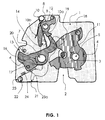
- FIG. 1 is a plan view of a wall 1 of a vehicle lock shown.
- the wall 1 may be a lock plate or part of a lock case.
- the wall 1 is preferably made of metal.
- the wall 1 is provided with an inlet slot 2 into which a locking bolt 3 of a vehicle door or a vehicle door enters when the associated vehicle door or vehicle door is closed.
- a rotary latch 4 is pivotally mounted on the wall 1 and can be rotated about its mounting axis 5.
- FIG. 1 the position of the main catch of the rotary latch is shown, in which the locking pin 3 located in the wall inlet slot 2 is enclosed by the inlet slot of the rotary latch so that the locking pin 3 can not be moved out of the wall inlet slot 2.
- the corresponding door or the flap of the vehicle is thus closed by the latching of the pawl in the main catch position of the catch. Shown is the position main rest, because a turning back of the catch according to the arrow direction shown 11 in the open position by the pivotally mounted main locking - pawl 6 is prevented as shown.
- the main catch pawl 6 is also on the wall 1 attached and can be rotated about its mounting axis 7.
- the catch is preferably by a in the FIG. 1 spring not shown biased towards the open position. Due to this bias the rotary latch presses against a stop of the main catch - pawl with an oblique course. This oblique course presses the main catch - pawl 6 out of the detent position. It is thus introduced such an opening moment in the main catch pawl 6.
- the rotary latch 4 is not biased by a spring, at least the locking bolt 3 causes a rotary movement of the rotary latch 4 in the direction of the open position according to arrow 11 when an associated vehicle door or vehicle door is opened. The associated torque then pushes the main catch pawl 6 out of the detent position.
- a pivotally mounted blocking lever 8 as shown.
- the blocking lever 8 is also pivotally mounted on the wall 1 and can be rotated about its mounting axis 9.
- an arm 10b of a spring 10 At a lateral contour region of the blocking lever 8 is an arm 10b of a spring 10 at.
- the spring 10 is biased so that the arm 10b of the spring 10 pushes the blocking lever 8 in the direction of the blockage position shown.
- the rotational movement of the blocking lever caused thereby is limited, as shown, by a stop 12, which is fastened to the wall 1 in the form of a protruding bolt.
- a pivotable pre - locking pawl 13 is disposed above the main catch pawl 6, which is shown transparent to allow the view of the underlying components.
- the pre-locking pawl 13 is also rotatably mounted on the axis 7 and thus can be rotated about this axis 7.
- the outline of the pre-locking pawl 13 is shown in dotted.
- the Vorrast - Pawl 13 includes one in the case of FIG. 1 also transparent daretseten bolt 14, which extends from the pre-locking pawl 13 in the direction of the wall 1 down. At this bolt 14, which is attached to the pre-locking pawl, the other arm 10a of the spring 10 abuts.
- the bolt 14 In the position of the main catch of the rotary latch, the bolt 14 also bears against a lateral contour area of the blocking lever 8. If the pre-locking pawl 13 is rotated by operating the lever arm 21 in the direction of the arrow 16, the bolt 14 causes the blocking lever 8 is rotated out of the blocking position. If the blocking lever 8 is moved out of the blocking position, the main locking pawl 6 is pushed out of its shown locking position by the rotary catch 4. Additionally or alternatively detects a lateral contour portion of the pre-locking pawl 13 as a result of said rotational movement a protruding serving as a stop pin 17 which is mounted on the main catch pawl 6. This has the consequence that the main catch pawl 6 is rotated out of the detent position shown and releases the catch. This then pivots in the direction of the arrow 11 in the direction of the open position and finally releases the locking pin 3. The associated door or flap can then be opened.
- the pre-locking pawl 13 can also lock the catch 4 when a protruding pin 18 of the catch 2 impinges on the lateral locking surface 19 of the pre-locking pawl 13 and thus prevents rotation of the pawl in the open position according to arrow 11.
- the pre-locking pawl 13 is preferably biased by a spring, not shown, in the direction of its detent position, ie as the blocking lever spring-loaded.
- the castle according to the FIG. 1 comprises a prestressed spring 23, with which the main-locking pawl 6 from its non-latching position, So from their initial position towards the end position, ie in the direction of their in the FIG. 1 shown detent position can be moved.
- the main catch pawl 6 is in the in FIG. 1 shown locking position, but in its end position, however, not spring-loaded, as this is prevented by the stop 24 for the spring arm 23a of the spring 23.
- the spring 23, the stop 24 and a stop for the other arm of the spring 23 are preferably attached to a particular plastic housing lock housing, which is not shown in the figure 1, since this would then hide the view of the components shown.
- the invention also includes the case that the pivotable component which is not spring-loaded in its end position, so in the present case, the main catch pawl 6 can be pivoted in addition by other components.
- such supplementary pivoting can be assisted, for example, by a rotational movement of the blocking lever 8 into the blocking position.
- additional pivoting is not absolutely necessary.
- the kinetic energy generated by the pivoting by means of spring force is sufficient to move the pivotable component to the end position, although the pivotable component is no longer spring-loaded in its end position.
- the spring 23 is preferably held by a mandrel 22, which is part of a plastic housing of the lock housing, that is, has been made in one piece with the lock housing.
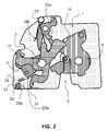
- FIG. 3 is the position of the rotary latch 4, the main latch pawl 6, the blocking lever 8, the spring 23, the spring 10 and the locking bolt 3 illustrated in the open position.
- the position of the pre-locking pawl 13 is sketched by a transparent representation.
- the locking pin 3 can now be moved out of the inlet slot 2 and the associated door or flap to be opened.
- the spring arm 23a has now been moved by the pivoting of the main-locking pawl 6 away from the stop 24 in the direction of the other spring arm 23b.
- the bias of the spring 23 has been increased.
- the spring 23 can now rotate by spring force the main catch - pawl 6 in the detent position.
- the main catch - pawl 6 is spring loaded by the spring 23.
- FIG. 4 an intermediate position between the open position and the main catch position of the rotary latch 4 is shown. If the rotary latch 4 is further rotated by the bolt 3 in the direction of the main catch position, the pre-locking pawl 13, which is shown transparently, can first latch into its locking position. In this in the FIG. 4 shown intermediate position, the main catch pawl 6 is still spring loaded by the spring 23.
- the main catch pawl 6 is still spring loaded even when the position is reached Vorrast. If the rotary latch 4 is rotated from the position Vorrast in the position of the main load, so this spring load is sufficient to move the main catch - pawl 6 in its locked position into it.
- FIG. 5 shows an enlarged view of the castle in the open position fragmentary and although seen in contrast to the preceding figures of the lock plate or the lock case of the castle.
- the FIG. 5 illustrates that the bearing mandrel 22 is integrally connected to the lock housing 25.
- the bearing mandrel 22 comprises two projecting lugs 22 a, which prevent the spring 23 from slipping out of the bearing mandrel 22.
- the projecting lugs 22 a are designed in such a ramp shape that the spring 23 through Touching and pressing can get into the mounted position shown.
- a lateral wall of the lock housing 25 has a projection 25a, which helps to keep the spring 23 in the desired position.
- the corresponding lateral wall also serves as a stop for the spring arm 23b, so that it remains permanently in the position shown.
- the stop 24 has a boom 24a, which is always above the spring arm 23a from the viewpoint of the lock case or the lock housing.
- the boom 24a also ensures that the spring arm 23a is held in the desired plane.
- the prestressed arm 23a of the spring 23 abuts against the main catch pawl 6.
- the main catch - pawl 6 is therefore spring loaded in this initial position.
Claims (10)
- Serrure destinée à une porte ou à un abattant, comprenant un mécanisme d'encliquetage composé d'un pêne tournant (4) et d'au moins un cliquet de blocage (6) et d'au moins un ressort (23) qui peut pivoter une composante pivotante de la serrure d'une position d'origine dans la direction d'une position finale par moyen de force de ressort, caractérisé en ce que dans la position finale aucune force de ressort n'agit sur la composante pivotante.
- Serrure selon la revendication précédente, caractérisée par une butée (24) destinée au ressort (23) laquelle a pour effet que le ressort (23) n'exerce aucune force de ressort sur la composante pivotante dans la position finale.
- Serrure selon la revendication précédente, caractérisée en ce que la butée (24) est montée sur un boîtier de serrure (25), une boîte de serrure ou une plaque de serrure ou qu'elle fait partie du boîtier de serrure (25), de la boîte de serrure ou de la plaque de serrure.
- Serrure selon l'une des revendications précédentes, caractérisée en ce que la composante pivotante est un cliquet de blocage (6, 13) et/ou un levier de blocage (8).
- Serrure selon l'une des revendications précédentes, caractérisée en ce que la serrure comprend une position de premier cran du pêne tournant et une position de deuxième cran du pêne tournant (4), la composante pivotante étant un cliquet de blocage (6) de deuxième cran.
- Serrure selon la revendication précédente, caractérisée en ce que le cliquet de blocage (6) de deuxième cran est sollicité par ressort dans la position de premier cran du pêne tournant (4) et/ou est sollicité par le ressort (23) dans la position ouverte du mécanisme d'encliquetage.
- Serrure selon l'une des revendications précédentes, caractérisée en ce que le ressort (23) est retenu par un mandrin de support (22) qui est relié d'une seule pièce au boîtier de serrure (25) de la serrure.
- Serrure selon l'une des revendications précédentes, caractérisée en ce que la serrure comprend un cliquet de blocage de deuxième cran (6) et un cliquet de blocage de premier cran (13).
- Serrure selon l'une des revendications précédentes, caractérisée en ce que le pêne tournant (4) peut entamer un mouvement ouvrant dans le cliquet de blocage (6) dans la position de deuxième cran du pêne tournant (4).
- Serrure selon l'une des revendications précédentes, caractérisée en ce qu'un bras (23a, 23b) du ressort est retenu ou guidé par un avant-bras (24a) d'une butée (24) destinée au ressort ou par une saillie (25a) d'un boîtier de serrure (25) de la serrure.
Applications Claiming Priority (2)
| Application Number | Priority Date | Filing Date | Title |
|---|---|---|---|
| DE102011004170A DE102011004170B4 (de) | 2011-02-15 | 2011-02-15 | Schloss für eine Klappe oder Tür |
| PCT/DE2012/000135 WO2012110025A2 (fr) | 2011-02-15 | 2012-02-14 | Serrure pour un panneau mobile ou une porte |
Publications (2)
| Publication Number | Publication Date |
|---|---|
| EP2675976A2 EP2675976A2 (fr) | 2013-12-25 |
| EP2675976B1 true EP2675976B1 (fr) | 2015-01-21 |
Family
ID=46026577
Family Applications (1)
| Application Number | Title | Priority Date | Filing Date |
|---|---|---|---|
| EP12718565.0A Active EP2675976B1 (fr) | 2011-02-15 | 2012-02-14 | Serrure pour un panneau mobile ou une porte |
Country Status (8)
| Country | Link |
|---|---|
| US (1) | US20150204121A1 (fr) |
| EP (1) | EP2675976B1 (fr) |
| JP (1) | JP6186604B2 (fr) |
| KR (1) | KR101985554B1 (fr) |
| CN (1) | CN103477009B (fr) |
| DE (1) | DE102011004170B4 (fr) |
| RU (1) | RU2633254C2 (fr) |
| WO (1) | WO2012110025A2 (fr) |
Families Citing this family (6)
| Publication number | Priority date | Publication date | Assignee | Title |
|---|---|---|---|---|
| DE102013213934A1 (de) | 2013-07-16 | 2015-01-22 | Kiekert Ag | Kraftfahrzeugschloss mit Positionssicherung nebst Herstellung |
| DE102014201799A1 (de) * | 2014-01-31 | 2015-08-06 | Kiekert Ag | Schließvorrichtung für eine Kraftfahrzeughaube und Verfahren |
| DE102014109111A1 (de) * | 2014-06-30 | 2015-12-31 | Kiekert Ag | Haubenschloss mit Steuerscheibe |
| DE102014115490A1 (de) * | 2014-10-24 | 2016-04-28 | Kiekert Ag | Kraftfahrzeugschloss mit Bremsklinke und Mitnehmermechanik |
| JP6535919B2 (ja) * | 2014-10-29 | 2019-07-03 | 三井金属アクト株式会社 | 車両用ドアラッチ装置および車両用ドアラッチ装置の組立方法 |
| RU184070U1 (ru) * | 2018-04-24 | 2018-10-15 | Акционерное общество "Ульяновский механический завод" | Замок для створок |
Family Cites Families (10)
| Publication number | Priority date | Publication date | Assignee | Title |
|---|---|---|---|---|
| JPS5532874B2 (fr) | 1973-01-25 | 1980-08-27 | ||
| CA1324726C (fr) * | 1988-09-26 | 1993-11-30 | Yoshikazu Hamada | Dispositif insonorisant pour mecanisme de verrouillage de vehicule |
| JPH0742818B2 (ja) * | 1988-09-26 | 1995-05-10 | 三井金属鉱業株式会社 | 車両用扉における開扉音防止装置 |
| DE19624640C1 (de) * | 1996-06-20 | 1998-01-08 | Kiekert Ag | Kraftfahrzeugtürverschluß mit Drehfalle, Sperrklinke und Blockiervorrichtung |
| DE102004040157B3 (de) * | 2004-08-19 | 2006-07-13 | Huf Hülsbeck & Fürst Gmbh & Co. Kg | Schloss für Türen oder Klappen an Fahrzeugen |
| DE102004052599A1 (de) * | 2004-10-29 | 2006-05-04 | Bayerische Motoren Werke Ag | Schloss an einer Tür oder Klappe, mit einer Öffnungshilfe, insbesondere für Fahrzeugtüren |
| DE102007003948A1 (de) | 2006-11-22 | 2008-05-29 | Kiekert Ag | Schlosseinheit mit mehrteiliger Sperrklinke |
| DE102008048712A1 (de) * | 2008-09-24 | 2010-03-25 | Kiekert Ag | Schlosseinheit mit Mehrklinken-Gesperre |
| US20100127512A1 (en) * | 2008-11-26 | 2010-05-27 | Inteva Products Llp | Vehicle door latch |
| US8235428B2 (en) * | 2009-07-14 | 2012-08-07 | Kiekert Ag | Lock unit having a slotted pawl |
-
2011
- 2011-02-15 DE DE102011004170A patent/DE102011004170B4/de not_active Expired - Fee Related
-
2012
- 2012-02-14 JP JP2013553789A patent/JP6186604B2/ja active Active
- 2012-02-14 RU RU2013140477A patent/RU2633254C2/ru not_active IP Right Cessation
- 2012-02-14 KR KR1020137023349A patent/KR101985554B1/ko active IP Right Grant
- 2012-02-14 EP EP12718565.0A patent/EP2675976B1/fr active Active
- 2012-02-14 CN CN201280018469.7A patent/CN103477009B/zh active Active
- 2012-02-14 WO PCT/DE2012/000135 patent/WO2012110025A2/fr active Application Filing
- 2012-02-14 US US13/985,607 patent/US20150204121A1/en not_active Abandoned
Also Published As
| Publication number | Publication date |
|---|---|
| US20150204121A1 (en) | 2015-07-23 |
| RU2633254C2 (ru) | 2017-10-11 |
| JP6186604B2 (ja) | 2017-08-30 |
| CN103477009B (zh) | 2016-08-10 |
| DE102011004170A1 (de) | 2012-08-16 |
| WO2012110025A3 (fr) | 2012-11-08 |
| EP2675976A2 (fr) | 2013-12-25 |
| WO2012110025A2 (fr) | 2012-08-23 |
| CN103477009A (zh) | 2013-12-25 |
| DE102011004170B4 (de) | 2012-09-13 |
| KR101985554B1 (ko) | 2019-06-03 |
| KR20140048846A (ko) | 2014-04-24 |
| RU2013140477A (ru) | 2015-03-27 |
| JP2014510206A (ja) | 2014-04-24 |
Similar Documents
| Publication | Publication Date | Title |
|---|---|---|
| EP2675975B1 (fr) | Serrure pour un panneau mobile ou une porte | |
| EP2304139B1 (fr) | Serrure a levier de blocage et centre de gravite reequilibre | |
| EP2440730B1 (fr) | Serrure avec guidage forcé du cliquet | |
| EP2440729B1 (fr) | Serrure de véhicule automobile avec système d'assistance à la fermeture | |
| EP2675976B1 (fr) | Serrure pour un panneau mobile ou une porte | |
| EP1617023B1 (fr) | Serrure pour ouvrants ou portes d'un véhicule | |
| EP2929112B1 (fr) | Serrure pour un coffre ou une porte | |
| EP2823120B1 (fr) | Serrure pour hayon ou porte | |
| DE102009029023A1 (de) | Kraftfahrzeugschloss | |
| EP2929114B1 (fr) | Serrure pour une trappe ou une porte | |
| DE2839070B2 (de) | Verschluß, insbesondere für Türen o.dgl. von Kraftfahrzeugen | |
| DE102012017677A1 (de) | Kraftfahrzeugtürschloss | |
| DE102011076704A1 (de) | Schloss für eine Klappe oder Tür | |
| DE102009029041A1 (de) | Kraftfahrzeugschloss | |
| EP2094924B1 (fr) | Serrure pour portes d'aéronefs, en particulier d'hélicoptères | |
| DE102009046880A1 (de) | Kraftfahrzeugschloss | |
| DE102009029674B4 (de) | Kraftfahrzeugschloss | |
| DE102009026919A1 (de) | Schloss mit steuerbarer Vorspannung | |
| EP2545234A2 (fr) | Serrure de véhicule à moteur présentant une transmission de force sur le palastre | |
| DE102012207440A1 (de) | Schloss für eine Klappe oder Tür | |
| DE102009026452B4 (de) | Auslösehebel mit einer ein öffnendes Moment für die Drehfalle erzeugenden Kontur bei Mehrklinken-Gesperre | |
| DE102005015515A1 (de) | Drehfallenverschluss | |
| WO2012016554A2 (fr) | Serrure pour véhicule automobile ou bâtiment | |
| DE102013103479A1 (de) | Türöffner |
Legal Events
| Date | Code | Title | Description |
|---|---|---|---|
| PUAI | Public reference made under article 153(3) epc to a published international application that has entered the european phase |
Free format text: ORIGINAL CODE: 0009012 |
|
| 17P | Request for examination filed |
Effective date: 20130829 |
|
| AK | Designated contracting states |
Kind code of ref document: A2 Designated state(s): AL AT BE BG CH CY CZ DE DK EE ES FI FR GB GR HR HU IE IS IT LI LT LU LV MC MK MT NL NO PL PT RO RS SE SI SK SM TR |
|
| DAX | Request for extension of the european patent (deleted) | ||
| REG | Reference to a national code |
Ref country code: DE Ref legal event code: R079 Ref document number: 502012002184 Country of ref document: DE Free format text: PREVIOUS MAIN CLASS: E05B0065320000 Ipc: E05B0085260000 |
|
| GRAP | Despatch of communication of intention to grant a patent |
Free format text: ORIGINAL CODE: EPIDOSNIGR1 |
|
| RIC1 | Information provided on ipc code assigned before grant |
Ipc: E05B 15/04 20060101ALI20140923BHEP Ipc: E05B 85/26 20140101AFI20140923BHEP |
|
| INTG | Intention to grant announced |
Effective date: 20141008 |
|
| GRAS | Grant fee paid |
Free format text: ORIGINAL CODE: EPIDOSNIGR3 |
|
| GRAA | (expected) grant |
Free format text: ORIGINAL CODE: 0009210 |
|
| AK | Designated contracting states |
Kind code of ref document: B1 Designated state(s): AL AT BE BG CH CY CZ DE DK EE ES FI FR GB GR HR HU IE IS IT LI LT LU LV MC MK MT NL NO PL PT RO RS SE SI SK SM TR |
|
| REG | Reference to a national code |
Ref country code: GB Ref legal event code: FG4D Free format text: NOT ENGLISH |
|
| REG | Reference to a national code |
Ref country code: CH Ref legal event code: EP |
|
| REG | Reference to a national code |
Ref country code: IE Ref legal event code: FG4D Free format text: LANGUAGE OF EP DOCUMENT: GERMAN |
|
| REG | Reference to a national code |
Ref country code: DE Ref legal event code: R096 Ref document number: 502012002184 Country of ref document: DE Effective date: 20150305 |
|
| REG | Reference to a national code |
Ref country code: AT Ref legal event code: REF Ref document number: 709283 Country of ref document: AT Kind code of ref document: T Effective date: 20150315 |
|
| REG | Reference to a national code |
Ref country code: NL Ref legal event code: VDEP Effective date: 20150121 |
|
| REG | Reference to a national code |
Ref country code: LT Ref legal event code: MG4D |
|
| PG25 | Lapsed in a contracting state [announced via postgrant information from national office to epo] |
Ref country code: BE Free format text: LAPSE BECAUSE OF NON-PAYMENT OF DUE FEES Effective date: 20150228 |
|
| PG25 | Lapsed in a contracting state [announced via postgrant information from national office to epo] |
Ref country code: FI Free format text: LAPSE BECAUSE OF FAILURE TO SUBMIT A TRANSLATION OF THE DESCRIPTION OR TO PAY THE FEE WITHIN THE PRESCRIBED TIME-LIMIT Effective date: 20150121 Ref country code: ES Free format text: LAPSE BECAUSE OF FAILURE TO SUBMIT A TRANSLATION OF THE DESCRIPTION OR TO PAY THE FEE WITHIN THE PRESCRIBED TIME-LIMIT Effective date: 20150121 Ref country code: LT Free format text: LAPSE BECAUSE OF FAILURE TO SUBMIT A TRANSLATION OF THE DESCRIPTION OR TO PAY THE FEE WITHIN THE PRESCRIBED TIME-LIMIT Effective date: 20150121 Ref country code: NO Free format text: LAPSE BECAUSE OF FAILURE TO SUBMIT A TRANSLATION OF THE DESCRIPTION OR TO PAY THE FEE WITHIN THE PRESCRIBED TIME-LIMIT Effective date: 20150421 Ref country code: SE Free format text: LAPSE BECAUSE OF FAILURE TO SUBMIT A TRANSLATION OF THE DESCRIPTION OR TO PAY THE FEE WITHIN THE PRESCRIBED TIME-LIMIT Effective date: 20150121 Ref country code: BG Free format text: LAPSE BECAUSE OF FAILURE TO SUBMIT A TRANSLATION OF THE DESCRIPTION OR TO PAY THE FEE WITHIN THE PRESCRIBED TIME-LIMIT Effective date: 20150421 Ref country code: HR Free format text: LAPSE BECAUSE OF FAILURE TO SUBMIT A TRANSLATION OF THE DESCRIPTION OR TO PAY THE FEE WITHIN THE PRESCRIBED TIME-LIMIT Effective date: 20150121 |
|
| PG25 | Lapsed in a contracting state [announced via postgrant information from national office to epo] |
Ref country code: RS Free format text: LAPSE BECAUSE OF FAILURE TO SUBMIT A TRANSLATION OF THE DESCRIPTION OR TO PAY THE FEE WITHIN THE PRESCRIBED TIME-LIMIT Effective date: 20150121 Ref country code: PL Free format text: LAPSE BECAUSE OF FAILURE TO SUBMIT A TRANSLATION OF THE DESCRIPTION OR TO PAY THE FEE WITHIN THE PRESCRIBED TIME-LIMIT Effective date: 20150121 Ref country code: GR Free format text: LAPSE BECAUSE OF FAILURE TO SUBMIT A TRANSLATION OF THE DESCRIPTION OR TO PAY THE FEE WITHIN THE PRESCRIBED TIME-LIMIT Effective date: 20150422 Ref country code: NL Free format text: LAPSE BECAUSE OF FAILURE TO SUBMIT A TRANSLATION OF THE DESCRIPTION OR TO PAY THE FEE WITHIN THE PRESCRIBED TIME-LIMIT Effective date: 20150121 Ref country code: IS Free format text: LAPSE BECAUSE OF FAILURE TO SUBMIT A TRANSLATION OF THE DESCRIPTION OR TO PAY THE FEE WITHIN THE PRESCRIBED TIME-LIMIT Effective date: 20150521 Ref country code: LV Free format text: LAPSE BECAUSE OF FAILURE TO SUBMIT A TRANSLATION OF THE DESCRIPTION OR TO PAY THE FEE WITHIN THE PRESCRIBED TIME-LIMIT Effective date: 20150121 |
|
| REG | Reference to a national code |
Ref country code: CH Ref legal event code: PL |
|
| REG | Reference to a national code |
Ref country code: DE Ref legal event code: R097 Ref document number: 502012002184 Country of ref document: DE |
|
| PG25 | Lapsed in a contracting state [announced via postgrant information from national office to epo] |
Ref country code: MC Free format text: LAPSE BECAUSE OF FAILURE TO SUBMIT A TRANSLATION OF THE DESCRIPTION OR TO PAY THE FEE WITHIN THE PRESCRIBED TIME-LIMIT Effective date: 20150121 Ref country code: DK Free format text: LAPSE BECAUSE OF FAILURE TO SUBMIT A TRANSLATION OF THE DESCRIPTION OR TO PAY THE FEE WITHIN THE PRESCRIBED TIME-LIMIT Effective date: 20150121 Ref country code: CH Free format text: LAPSE BECAUSE OF NON-PAYMENT OF DUE FEES Effective date: 20150228 Ref country code: RO Free format text: LAPSE BECAUSE OF FAILURE TO SUBMIT A TRANSLATION OF THE DESCRIPTION OR TO PAY THE FEE WITHIN THE PRESCRIBED TIME-LIMIT Effective date: 20150121 Ref country code: SK Free format text: LAPSE BECAUSE OF FAILURE TO SUBMIT A TRANSLATION OF THE DESCRIPTION OR TO PAY THE FEE WITHIN THE PRESCRIBED TIME-LIMIT Effective date: 20150121 Ref country code: LI Free format text: LAPSE BECAUSE OF NON-PAYMENT OF DUE FEES Effective date: 20150228 Ref country code: EE Free format text: LAPSE BECAUSE OF FAILURE TO SUBMIT A TRANSLATION OF THE DESCRIPTION OR TO PAY THE FEE WITHIN THE PRESCRIBED TIME-LIMIT Effective date: 20150121 |
|
| REG | Reference to a national code |
Ref country code: IE Ref legal event code: MM4A |
|
| PLBE | No opposition filed within time limit |
Free format text: ORIGINAL CODE: 0009261 |
|
| STAA | Information on the status of an ep patent application or granted ep patent |
Free format text: STATUS: NO OPPOSITION FILED WITHIN TIME LIMIT |
|
| 26N | No opposition filed |
Effective date: 20151022 |
|
| PG25 | Lapsed in a contracting state [announced via postgrant information from national office to epo] |
Ref country code: IT Free format text: LAPSE BECAUSE OF FAILURE TO SUBMIT A TRANSLATION OF THE DESCRIPTION OR TO PAY THE FEE WITHIN THE PRESCRIBED TIME-LIMIT Effective date: 20150121 |
|
| PG25 | Lapsed in a contracting state [announced via postgrant information from national office to epo] |
Ref country code: IE Free format text: LAPSE BECAUSE OF NON-PAYMENT OF DUE FEES Effective date: 20150214 |
|
| REG | Reference to a national code |
Ref country code: FR Ref legal event code: PLFP Year of fee payment: 5 |
|
| PG25 | Lapsed in a contracting state [announced via postgrant information from national office to epo] |
Ref country code: SI Free format text: LAPSE BECAUSE OF FAILURE TO SUBMIT A TRANSLATION OF THE DESCRIPTION OR TO PAY THE FEE WITHIN THE PRESCRIBED TIME-LIMIT Effective date: 20150121 |
|
| GBPC | Gb: european patent ceased through non-payment of renewal fee |
Effective date: 20160214 |
|
| PG25 | Lapsed in a contracting state [announced via postgrant information from national office to epo] |
Ref country code: MT Free format text: LAPSE BECAUSE OF FAILURE TO SUBMIT A TRANSLATION OF THE DESCRIPTION OR TO PAY THE FEE WITHIN THE PRESCRIBED TIME-LIMIT Effective date: 20150121 |
|
| PG25 | Lapsed in a contracting state [announced via postgrant information from national office to epo] |
Ref country code: GB Free format text: LAPSE BECAUSE OF NON-PAYMENT OF DUE FEES Effective date: 20160214 |
|
| REG | Reference to a national code |
Ref country code: FR Ref legal event code: PLFP Year of fee payment: 6 |
|
| PG25 | Lapsed in a contracting state [announced via postgrant information from national office to epo] |
Ref country code: HU Free format text: LAPSE BECAUSE OF FAILURE TO SUBMIT A TRANSLATION OF THE DESCRIPTION OR TO PAY THE FEE WITHIN THE PRESCRIBED TIME-LIMIT; INVALID AB INITIO Effective date: 20120214 Ref country code: SM Free format text: LAPSE BECAUSE OF FAILURE TO SUBMIT A TRANSLATION OF THE DESCRIPTION OR TO PAY THE FEE WITHIN THE PRESCRIBED TIME-LIMIT Effective date: 20150121 |
|
| PG25 | Lapsed in a contracting state [announced via postgrant information from national office to epo] |
Ref country code: CY Free format text: LAPSE BECAUSE OF FAILURE TO SUBMIT A TRANSLATION OF THE DESCRIPTION OR TO PAY THE FEE WITHIN THE PRESCRIBED TIME-LIMIT Effective date: 20150121 |
|
| PG25 | Lapsed in a contracting state [announced via postgrant information from national office to epo] |
Ref country code: PT Free format text: LAPSE BECAUSE OF FAILURE TO SUBMIT A TRANSLATION OF THE DESCRIPTION OR TO PAY THE FEE WITHIN THE PRESCRIBED TIME-LIMIT Effective date: 20150521 |
|
| PG25 | Lapsed in a contracting state [announced via postgrant information from national office to epo] |
Ref country code: TR Free format text: LAPSE BECAUSE OF FAILURE TO SUBMIT A TRANSLATION OF THE DESCRIPTION OR TO PAY THE FEE WITHIN THE PRESCRIBED TIME-LIMIT Effective date: 20150121 |
|
| PG25 | Lapsed in a contracting state [announced via postgrant information from national office to epo] |
Ref country code: LU Free format text: LAPSE BECAUSE OF NON-PAYMENT OF DUE FEES Effective date: 20150214 |
|
| REG | Reference to a national code |
Ref country code: FR Ref legal event code: PLFP Year of fee payment: 7 |
|
| REG | Reference to a national code |
Ref country code: AT Ref legal event code: MM01 Ref document number: 709283 Country of ref document: AT Kind code of ref document: T Effective date: 20170214 |
|
| PG25 | Lapsed in a contracting state [announced via postgrant information from national office to epo] |
Ref country code: AT Free format text: LAPSE BECAUSE OF NON-PAYMENT OF DUE FEES Effective date: 20170214 |
|
| PG25 | Lapsed in a contracting state [announced via postgrant information from national office to epo] |
Ref country code: MK Free format text: LAPSE BECAUSE OF FAILURE TO SUBMIT A TRANSLATION OF THE DESCRIPTION OR TO PAY THE FEE WITHIN THE PRESCRIBED TIME-LIMIT Effective date: 20150121 |
|
| PG25 | Lapsed in a contracting state [announced via postgrant information from national office to epo] |
Ref country code: AL Free format text: LAPSE BECAUSE OF FAILURE TO SUBMIT A TRANSLATION OF THE DESCRIPTION OR TO PAY THE FEE WITHIN THE PRESCRIBED TIME-LIMIT Effective date: 20150121 |
|
| PGFP | Annual fee paid to national office [announced via postgrant information from national office to epo] |
Ref country code: FR Payment date: 20230220 Year of fee payment: 12 Ref country code: CZ Payment date: 20230202 Year of fee payment: 12 |
|
| PGFP | Annual fee paid to national office [announced via postgrant information from national office to epo] |
Ref country code: DE Payment date: 20230216 Year of fee payment: 12 |
|
| P01 | Opt-out of the competence of the unified patent court (upc) registered |
Effective date: 20230529 |