EP2675976B1 - Lock for a flap or door - Google Patents
Lock for a flap or door Download PDFInfo
- Publication number
- EP2675976B1 EP2675976B1 EP12718565.0A EP12718565A EP2675976B1 EP 2675976 B1 EP2675976 B1 EP 2675976B1 EP 12718565 A EP12718565 A EP 12718565A EP 2675976 B1 EP2675976 B1 EP 2675976B1
- Authority
- EP
- European Patent Office
- Prior art keywords
- lock
- spring
- pawl
- catch
- rotary latch
- Prior art date
- Legal status (The legal status is an assumption and is not a legal conclusion. Google has not performed a legal analysis and makes no representation as to the accuracy of the status listed.)
- Active
Links
Images


Classifications
-
- E—FIXED CONSTRUCTIONS
- E05—LOCKS; KEYS; WINDOW OR DOOR FITTINGS; SAFES
- E05B—LOCKS; ACCESSORIES THEREFOR; HANDCUFFS
- E05B15/00—Other details of locks; Parts for engagement by bolts of fastening devices
- E05B15/04—Spring arrangements in locks
-
- E—FIXED CONSTRUCTIONS
- E05—LOCKS; KEYS; WINDOW OR DOOR FITTINGS; SAFES
- E05B—LOCKS; ACCESSORIES THEREFOR; HANDCUFFS
- E05B77/00—Vehicle locks characterised by special functions or purposes
- E05B77/36—Noise prevention; Anti-rattling means
-
- E—FIXED CONSTRUCTIONS
- E05—LOCKS; KEYS; WINDOW OR DOOR FITTINGS; SAFES
- E05B—LOCKS; ACCESSORIES THEREFOR; HANDCUFFS
- E05B85/00—Details of vehicle locks not provided for in groups E05B77/00 - E05B83/00
- E05B85/20—Bolts or detents
- E05B85/24—Bolts rotating about an axis
-
- E—FIXED CONSTRUCTIONS
- E05—LOCKS; KEYS; WINDOW OR DOOR FITTINGS; SAFES
- E05B—LOCKS; ACCESSORIES THEREFOR; HANDCUFFS
- E05B85/00—Details of vehicle locks not provided for in groups E05B77/00 - E05B83/00
- E05B85/20—Bolts or detents
- E05B85/24—Bolts rotating about an axis
- E05B85/26—Cooperation between bolts and detents
-
- E—FIXED CONSTRUCTIONS
- E05—LOCKS; KEYS; WINDOW OR DOOR FITTINGS; SAFES
- E05C—BOLTS OR FASTENING DEVICES FOR WINGS, SPECIALLY FOR DOORS OR WINDOWS
- E05C3/00—Fastening devices with bolts moving pivotally or rotatively
- E05C3/12—Fastening devices with bolts moving pivotally or rotatively with latching action
- E05C3/124—Fastening devices with bolts moving pivotally or rotatively with latching action with latch under compression force between its pivot and the striker
-
- E—FIXED CONSTRUCTIONS
- E05—LOCKS; KEYS; WINDOW OR DOOR FITTINGS; SAFES
- E05C—BOLTS OR FASTENING DEVICES FOR WINGS, SPECIALLY FOR DOORS OR WINDOWS
- E05C5/00—Fastening devices with bolts moving otherwise than only rectilinearly and only pivotally or rotatively
-
- E—FIXED CONSTRUCTIONS
- E05—LOCKS; KEYS; WINDOW OR DOOR FITTINGS; SAFES
- E05B—LOCKS; ACCESSORIES THEREFOR; HANDCUFFS
- E05B15/00—Other details of locks; Parts for engagement by bolts of fastening devices
- E05B15/04—Spring arrangements in locks
- E05B2015/0431—Modifying spring characteristic or tension
-
- Y—GENERAL TAGGING OF NEW TECHNOLOGICAL DEVELOPMENTS; GENERAL TAGGING OF CROSS-SECTIONAL TECHNOLOGIES SPANNING OVER SEVERAL SECTIONS OF THE IPC; TECHNICAL SUBJECTS COVERED BY FORMER USPC CROSS-REFERENCE ART COLLECTIONS [XRACs] AND DIGESTS
- Y10—TECHNICAL SUBJECTS COVERED BY FORMER USPC
- Y10T—TECHNICAL SUBJECTS COVERED BY FORMER US CLASSIFICATION
- Y10T292/00—Closure fasteners
- Y10T292/08—Bolts
- Y10T292/1043—Swinging
- Y10T292/1051—Spring projected
- Y10T292/1052—Operating means
Definitions
- the invention relates to a lock for a flap or a door having the features of the preamble of claim 1.
- the door or flap may be a door or flap of a motor vehicle or a building.
- the aforementioned lock comprises a locking mechanism with a catch and at least one pawl, with which the catch can be locked in a closed position.
- the locking mechanism is attached to a usually made of metal lock plate or a usually metal lock case.
- a lock also includes a lock housing, which is usually made of plastic and which is able to shield components of the castle to the outside.
- the invention particularly relates to a lock with a pawl for the position of the main catch of the catch (hereinafter called “main catch pawl”), a pawl for the position Vorrast the catch (hereinafter called “pre-locking pawl”) and a blocking lever for said main catch - pawl.
- main catch pawl a pawl for the position of the main catch of the catch
- pre-locking pawl a pawl for the position Vorrast the catch
- blocking lever for said main catch - pawl Such a lock is from the document DE 10 2007 003 948 A1 known.
- the catch of the out of the DE 10 2007 003 948 A1 known motor vehicle lock has a fork-shaped inlet slot into which a locking bolt of a vehicle door or a vehicle door, when the vehicle door or vehicle door is closed.
- the locking pin then rotates the catch from an open position to a closed position. If the catch has reached a closed position, so the locking pin can not leave the inlet slot of the catch. In the closed position, the pawl locks the catch, so that it can not be rotated back into the open position. The lock is then in a locked position or position.
- A1 known lock comprises two grate positions, which can be taken in succession during the closing of the rotary latch, namely the so-called pre-locking position of the rotary latch and the so-called main catch position of the rotary latch.
- a blocking lever may be provided which blocks such movement when the catch is locked.
- a blocking lever is in the from the publication DE 10 2007 003 948 A1 known lock for the main catch pawl required because the catch and the main catch pawl are designed so that in the position of the main catch, the catch in the main catch pawl is able to initiate an opening moment.
- a prestressed spring is capable, for example, of moving a pawl into its detent position, of moving a blocking lever into its blocking position or of turning a catch into its open position DE 10 2007 003 948 A1 a spring-loaded rotary latch known So a catch that can be pivoted by means of spring force of the associated spring.
- a lock for a door or flap is provided with a catch of rotary latch and at least one pawl and a spring.
- the spring can pivot a pivotable component of the lock by spring force from a starting position in the direction of an end position. In the end position, however, no spring force acts on the pivotable component. The pivotable component thus falls without the pressure of the spring in the end position. As a result, a significant reduction in noise is achieved in comparison to the case that the pressure of the spring acts on the pivotable component up to the end position.
- the spring load of the pivotable component preferably ends shortly before reaching the end position. It is thus ensured in a particularly reliable manner that the pivotable component reaches its end position.
- the pivotable component from reaching a no longer spring-loaded position only has to be rotated by a few degrees in order to reach the end position.
- the component then only has to travel a short distance without the assistance of the spring force.
- the component must be rotated by not more than 5 °, preferably not more than 3 °, more preferably not more than 1 ° to reach the end position without acting spring force.
- the lock advantageously comprises a stop for the spring.
- the stop causes in the end position and preferably also shortly before no spring force of the spring acts on the pivotable component.
- the bias of the spring can thus be chosen so that the pivotable component is pivoted at a desired speed and / or with a sufficient force.
- the pivotable component is therefore not spring-loaded in the end position, even if the spring was relatively strongly biased, inter alia, in the starting position.
- the stop is expediently attached to a lock housing, a lock case or a lock plate of the lock.
- the stopper is part of the lock housing, part of the lock case or part of the lock plate.
- the stop is then made in one piece with the lock housing, the lock case or the lock plate. This minimizes the number of parts to be produced.
- the pivotable component may be a pawl and / or a blocking lever.
- the respective component is then spring loaded in the initial position, but not in the end position. In the end position, therefore, the spring force does not affect the pivotable component. If the pivotable component is a pawl, then opening forces that have to be expended in order to move the pawl out of its rest position are reduced. It is thus achieved in this case, in addition to a significant noise reduction, another advantage.
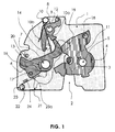
- FIG. 1 is a plan view of a wall 1 of a vehicle lock shown.
- the wall 1 may be a lock plate or part of a lock case.
- the wall 1 is preferably made of metal.
- the wall 1 is provided with an inlet slot 2 into which a locking bolt 3 of a vehicle door or a vehicle door enters when the associated vehicle door or vehicle door is closed.
- a rotary latch 4 is pivotally mounted on the wall 1 and can be rotated about its mounting axis 5.
- FIG. 1 the position of the main catch of the rotary latch is shown, in which the locking pin 3 located in the wall inlet slot 2 is enclosed by the inlet slot of the rotary latch so that the locking pin 3 can not be moved out of the wall inlet slot 2.
- the corresponding door or the flap of the vehicle is thus closed by the latching of the pawl in the main catch position of the catch. Shown is the position main rest, because a turning back of the catch according to the arrow direction shown 11 in the open position by the pivotally mounted main locking - pawl 6 is prevented as shown.
- the main catch pawl 6 is also on the wall 1 attached and can be rotated about its mounting axis 7.
- the catch is preferably by a in the FIG. 1 spring not shown biased towards the open position. Due to this bias the rotary latch presses against a stop of the main catch - pawl with an oblique course. This oblique course presses the main catch - pawl 6 out of the detent position. It is thus introduced such an opening moment in the main catch pawl 6.
- the rotary latch 4 is not biased by a spring, at least the locking bolt 3 causes a rotary movement of the rotary latch 4 in the direction of the open position according to arrow 11 when an associated vehicle door or vehicle door is opened. The associated torque then pushes the main catch pawl 6 out of the detent position.
- a pivotally mounted blocking lever 8 as shown.
- the blocking lever 8 is also pivotally mounted on the wall 1 and can be rotated about its mounting axis 9.
- an arm 10b of a spring 10 At a lateral contour region of the blocking lever 8 is an arm 10b of a spring 10 at.
- the spring 10 is biased so that the arm 10b of the spring 10 pushes the blocking lever 8 in the direction of the blockage position shown.
- the rotational movement of the blocking lever caused thereby is limited, as shown, by a stop 12, which is fastened to the wall 1 in the form of a protruding bolt.
- a pivotable pre - locking pawl 13 is disposed above the main catch pawl 6, which is shown transparent to allow the view of the underlying components.
- the pre-locking pawl 13 is also rotatably mounted on the axis 7 and thus can be rotated about this axis 7.
- the outline of the pre-locking pawl 13 is shown in dotted.
- the Vorrast - Pawl 13 includes one in the case of FIG. 1 also transparent daretseten bolt 14, which extends from the pre-locking pawl 13 in the direction of the wall 1 down. At this bolt 14, which is attached to the pre-locking pawl, the other arm 10a of the spring 10 abuts.
- the bolt 14 In the position of the main catch of the rotary latch, the bolt 14 also bears against a lateral contour area of the blocking lever 8. If the pre-locking pawl 13 is rotated by operating the lever arm 21 in the direction of the arrow 16, the bolt 14 causes the blocking lever 8 is rotated out of the blocking position. If the blocking lever 8 is moved out of the blocking position, the main locking pawl 6 is pushed out of its shown locking position by the rotary catch 4. Additionally or alternatively detects a lateral contour portion of the pre-locking pawl 13 as a result of said rotational movement a protruding serving as a stop pin 17 which is mounted on the main catch pawl 6. This has the consequence that the main catch pawl 6 is rotated out of the detent position shown and releases the catch. This then pivots in the direction of the arrow 11 in the direction of the open position and finally releases the locking pin 3. The associated door or flap can then be opened.
- the pre-locking pawl 13 can also lock the catch 4 when a protruding pin 18 of the catch 2 impinges on the lateral locking surface 19 of the pre-locking pawl 13 and thus prevents rotation of the pawl in the open position according to arrow 11.
- the pre-locking pawl 13 is preferably biased by a spring, not shown, in the direction of its detent position, ie as the blocking lever spring-loaded.
- the castle according to the FIG. 1 comprises a prestressed spring 23, with which the main-locking pawl 6 from its non-latching position, So from their initial position towards the end position, ie in the direction of their in the FIG. 1 shown detent position can be moved.
- the main catch pawl 6 is in the in FIG. 1 shown locking position, but in its end position, however, not spring-loaded, as this is prevented by the stop 24 for the spring arm 23a of the spring 23.
- the spring 23, the stop 24 and a stop for the other arm of the spring 23 are preferably attached to a particular plastic housing lock housing, which is not shown in the figure 1, since this would then hide the view of the components shown.
- the invention also includes the case that the pivotable component which is not spring-loaded in its end position, so in the present case, the main catch pawl 6 can be pivoted in addition by other components.
- such supplementary pivoting can be assisted, for example, by a rotational movement of the blocking lever 8 into the blocking position.
- additional pivoting is not absolutely necessary.
- the kinetic energy generated by the pivoting by means of spring force is sufficient to move the pivotable component to the end position, although the pivotable component is no longer spring-loaded in its end position.
- the spring 23 is preferably held by a mandrel 22, which is part of a plastic housing of the lock housing, that is, has been made in one piece with the lock housing.
- FIG. 3 is the position of the rotary latch 4, the main latch pawl 6, the blocking lever 8, the spring 23, the spring 10 and the locking bolt 3 illustrated in the open position.
- the position of the pre-locking pawl 13 is sketched by a transparent representation.
- the locking pin 3 can now be moved out of the inlet slot 2 and the associated door or flap to be opened.
- the spring arm 23a has now been moved by the pivoting of the main-locking pawl 6 away from the stop 24 in the direction of the other spring arm 23b.
- the bias of the spring 23 has been increased.
- the spring 23 can now rotate by spring force the main catch - pawl 6 in the detent position.
- the main catch - pawl 6 is spring loaded by the spring 23.
- FIG. 4 an intermediate position between the open position and the main catch position of the rotary latch 4 is shown. If the rotary latch 4 is further rotated by the bolt 3 in the direction of the main catch position, the pre-locking pawl 13, which is shown transparently, can first latch into its locking position. In this in the FIG. 4 shown intermediate position, the main catch pawl 6 is still spring loaded by the spring 23.
- the main catch pawl 6 is still spring loaded even when the position is reached Vorrast. If the rotary latch 4 is rotated from the position Vorrast in the position of the main load, so this spring load is sufficient to move the main catch - pawl 6 in its locked position into it.
- FIG. 5 shows an enlarged view of the castle in the open position fragmentary and although seen in contrast to the preceding figures of the lock plate or the lock case of the castle.
- the FIG. 5 illustrates that the bearing mandrel 22 is integrally connected to the lock housing 25.
- the bearing mandrel 22 comprises two projecting lugs 22 a, which prevent the spring 23 from slipping out of the bearing mandrel 22.
- the projecting lugs 22 a are designed in such a ramp shape that the spring 23 through Touching and pressing can get into the mounted position shown.
- a lateral wall of the lock housing 25 has a projection 25a, which helps to keep the spring 23 in the desired position.
- the corresponding lateral wall also serves as a stop for the spring arm 23b, so that it remains permanently in the position shown.
- the stop 24 has a boom 24a, which is always above the spring arm 23a from the viewpoint of the lock case or the lock housing.
- the boom 24a also ensures that the spring arm 23a is held in the desired plane.
- the prestressed arm 23a of the spring 23 abuts against the main catch pawl 6.
- the main catch - pawl 6 is therefore spring loaded in this initial position.
Description
Die Erfindung betrifft ein Schloss für eine Klappe oder eine Tür mit den Merkmalen des Oberbegriffs des Anspruchs 1. Bei der Tür oder Klappe kann es sich um eine Tür oder Klappe eines Kraftfahrzeugs oder eines Gebäudes handeln.The invention relates to a lock for a flap or a door having the features of the preamble of
Das eingangs genannte Schloss umfasst ein Gesperre mit einer Drehfalle und mindestens einer Sperrklinke, mit der die Drehfalle in einer Schließstellung verrastet werden kann. Das Gesperre wird an einer in der Regel aus Metall bestehenden Schlossplatte oder einem in der Regel aus Metall bestehenden Schlosskasten angebracht. Üblicherweise umfasst ein solches Schloss darüber hinaus ein Schlossgehäuse, welches in der Regel aus Kunststoff besteht und welches Komponenten des Schlosses nach außen abzuschirmen vermag. Darüber hinaus kann es einen insbesondere aus Kunststoff bestehenden Schlossdeckel und/ oder einen insbesondere aus Kunststoff bestehenden Deckel für eine Zentralverriegelung geben, die ebenfalls der Abschirmung dienen.The aforementioned lock comprises a locking mechanism with a catch and at least one pawl, with which the catch can be locked in a closed position. The locking mechanism is attached to a usually made of metal lock plate or a usually metal lock case. Usually, such a lock also includes a lock housing, which is usually made of plastic and which is able to shield components of the castle to the outside. In addition, there may be a particular existing plastic lock cover and / or a particular existing plastic cover for a central locking, which also serve the shield.
Die Erfindung betrifft insbesondere ein Schloss mit einer Sperrklinke für die Position Hauptrast der Drehfalle (nachfolgend "Hauptrast-Sperrklinke" genannt), einer Sperrklinke für die Position Vorrast der Drehfalle (nachfolgend "Vorrast-Sperrklinke" genannt) und einem Blockadehebel für die genannte Hauptrast - Sperrklinke. Ein solches Schloss ist aus der Druckschrift
Die Drehfalle des aus der
Das aus der
Um zu vermeiden, dass eine Sperrklinke nicht unplanmäßig aus seiner Raststellung heraus bewegt wird, kann ein Blockadehebel vorgesehen sein, der eine solche Bewegung blockiert, wenn die Drehfalle verrastet ist. Ein solcher Blockadehebel ist bei dem aus der Druckschrift
Die vorgenannten, aus dem Stand der Technik bereits bekannten Merkmale können einzeln oder in beliebiger Kombination mit dem Gegenstand der vorliegenden Erfindung kombiniert werden.The aforementioned features already known from the prior art can be combined individually or in any combination with the subject matter of the present invention.
Aus der Druckschrift
Bei einem Schloss der eingangs genannten Art gibt es also Komponenten wie Sperrklinke, Blockadehebel oder Drehfalle, die verschwenkt werden können und sollen. Regelmäßig gibt es zumindest eine vorgespannte Feder, mit der eine gewünschte Schwenkbewegung einer solchen Komponente durch Federkraft bewirkt wird. Eine solche vorgespannte Feder vermag beispielsweise eine Sperrklinke in ihre Raststellung hinein zu bewegen, einen Blockadehebel in seine blockierende Stellung hinein oder aber eine Drehfalle in ihre geöffnete Stellung, So ist aus der
Es ist Aufgabe der Erfindung, ein Schloss der eingangs genannten Art weiter zu entwickeln.It is an object of the invention to further develop a lock of the type mentioned.
Die Aufgabe der Erfindung wird durch ein Schloss mit den Merkmalen des ersten Anspruchs gelöst. Vorteilhafte Ausgestaltungen ergeben sich aus den Unteransprüchen.The object of the invention is achieved by a lock with the features of the first claim. Advantageous embodiments emerge from the subclaims.
Zur Lösung der Aufgabe wird ein Schloss für eine Tür oder Klappe mit einem Gesperre aus Drehfalle und mindestens einer Sperrklinke und einer Feder bereitgestellt. Die Feder kann eine verschwenkbare Komponente des Schlosses durch Federkraft von einer Ausgangsstellung in Richtung einer Endstellung verschwenken. In der Endstellung wirkt allerdings keine Federkraft auf die verschwenkbare Komponente ein. Die verschwenkbare Komponente fällt damit ohne den Druck der Feder in die Endstellung ein. Hierdurch wird eine erhebliche Geräuschminderung im Vergleich zu dem Fall erzielt, dass der Druck der Feder bis in die Endstellung hinein auf die verschwenkbare Komponente einwirkt.To achieve the object, a lock for a door or flap is provided with a catch of rotary latch and at least one pawl and a spring. The spring can pivot a pivotable component of the lock by spring force from a starting position in the direction of an end position. In the end position, however, no spring force acts on the pivotable component. The pivotable component thus falls without the pressure of the spring in the end position. As a result, a significant reduction in noise is achieved in comparison to the case that the pressure of the spring acts on the pivotable component up to the end position.
Die Federbelastung der verschwenkbaren Komponente endet vorzugsweise kurz vor dem Erreichen der Endstellung. Besonders zuverlässig wird so sichergestellt, dass die verschwenkbare Komponente ihre Endstellung erreicht. Hierunter ist zu verstehen, dass die verschwenkbare Komponente ab Erreichen einer nicht mehr federbelasteten Stellung lediglich um wenige Grad gedreht werden muss, um die Endstellung zu erreichen. Insbesondere muss die Komponente dann nur einen geringen Weg ohne Unterstützung durch die Federkraft zurücklegen. In einer Ausführungsform muss dann die Komponente um nicht mehr als 5°, vorzugsweise um nicht mehr als 3°, besonders bevorzugt um nicht mehr als 1° gedreht werden, um ohne einwirkende Federkraft die Endstellung zu erreichen.The spring load of the pivotable component preferably ends shortly before reaching the end position. It is thus ensured in a particularly reliable manner that the pivotable component reaches its end position. This is to be understood that the pivotable component from reaching a no longer spring-loaded position only has to be rotated by a few degrees in order to reach the end position. In particular, the component then only has to travel a short distance without the assistance of the spring force. In one embodiment, then the component must be rotated by not more than 5 °, preferably not more than 3 °, more preferably not more than 1 ° to reach the end position without acting spring force.
Damit in der Endstellung keine Federkraft mehr auf die verschwenkbare Komponente einwirkt, kann die Feder entsprechend schwach in der Ausgangsstellung vor gespannt sein. In einer Ausführungsform umfasst das Schloss jedoch vorteilhaft einen Anschlag für die Feder. Der Anschlag bewirkt, dass in der Endstellung sowie vorzugsweise auch kurz davor keine Federkraft der Feder auf die verschwenkbare Komponente einwirkt. Bei dieser Ausführungsform ist es möglich, die Feder in frei wählbarer Weise vorzuspannen. Die Vorspannung der Feder kann also so gewählt werden, dass die verschwenkbare Komponente mit einer gewünschten Geschwindigkeit und/ oder mit einer hinreichenden Kraft verschwenkt wird. Außerdem kann durch den Anschlag sichergestellt werden, dass keinesfalls eine Federkraft in der Endstellung auf die verschwenkbare Komponente einwirkt. Die verschwenkbare Komponente ist in der Endstellung also mit Sicherheit nicht federbelastet, selbst wenn die Feder unter anderem in der Ausgangsstellung relativ stark vorgespannt war.So that no spring force acts more on the pivotable component in the end position, the spring may be correspondingly weak in the starting position before tensioned. In one embodiment, however, the lock advantageously comprises a stop for the spring. The stop causes in the end position and preferably also shortly before no spring force of the spring acts on the pivotable component. In this embodiment, it is possible to bias the spring in a freely selectable manner. The bias of the spring can thus be chosen so that the pivotable component is pivoted at a desired speed and / or with a sufficient force. In addition, it can be ensured by the stop that under no circumstances acts a spring force in the end position on the pivotable component. The pivotable component is therefore not spring-loaded in the end position, even if the spring was relatively strongly biased, inter alia, in the starting position.
Der Anschlag ist zweckmäßiger Weise an einem Schlossgehäuse, einem Schlosskasten oder einer Schlossplatte des Schlosses angebracht. Bevorzugt ist der Anschlag Teil des Schlossgehäuses, Teil des Schlosskastens oder Teil der Schlossplatte. Der Anschlag ist dann einstückig mit dem Schlossgehäuse, dem Schlosskasten oder der Schlossplatte gefertigt. Dies minimiert die Zahl der herzustellenden Teile.The stop is expediently attached to a lock housing, a lock case or a lock plate of the lock. Preferably, the stopper is part of the lock housing, part of the lock case or part of the lock plate. The stop is then made in one piece with the lock housing, the lock case or the lock plate. This minimizes the number of parts to be produced.
Die verschwenkbare Komponente kann eine Sperrklinke und/ oder ein Blockadehebel sein. Die jeweilige Komponente ist dann zwar in der Ausgangsstellung federbelastet, nicht aber in der Endstellung. In der Endstellung wirkt also die Federkraft nicht auf die verschwenkbare Komponente ein. Ist die verschwenkbare Komponente eine Sperrklinke, so verringern sich Öffnungskräfte, die aufgewendet werden müssen, um die Sperrklinke aus ihrer Raststellung heraus zu bewegen. Es wird also in diesem Fall neben einer deutlichen Geräuschminderung ein weiterer Vorteil erzielt.The pivotable component may be a pawl and / or a blocking lever. The respective component is then spring loaded in the initial position, but not in the end position. In the end position, therefore, the spring force does not affect the pivotable component. If the pivotable component is a pawl, then opening forces that have to be expended in order to move the pawl out of its rest position are reduced. It is thus achieved in this case, in addition to a significant noise reduction, another advantage.
Nachfolgend wird ein in den Figuren dargestelltes bevorzugtes Ausführungsbeispiel der Erfindung näher erläutert. Anhand des Ausführungsbeispiels werden Vorteile von weiteren Ausführungsformen der Erfindung verdeutlicht.Hereinafter, a preferred embodiment of the invention shown in the figures will be explained in more detail. On the basis of the embodiment advantages of further embodiments of the invention are illustrated.
Es zeigen:
-
Fig. 1 : Gesperre in der Position Hauptrast der Drehfalle -
Fig. 2 : Gesperre in der Position Hauptrast der Drehfalle -
Fig. 3 : Gesperre in der geöffneten Stellung -
Fig. 4 : Gesperre in einer Zwischenstellung -
Fig. 5 : Ausschnitt in geöffneter Stellung -
Fig. 6 : Ausschnitt in Position Hauptrast der Drehfalle
-
Fig. 1 : Ratchet in the position of the main catch of the rotary latch -
Fig. 2 : Ratchet in the position of the main catch of the rotary latch -
Fig. 3 : Lock in the open position -
Fig. 4 : Lock in an intermediate position -
Fig. 5 : Cutout in open position -
Fig. 6 : Cutting in position of main catch of rotary latch
In der
Ist die Drehfalle 4 nicht durch eine Feder vorgespannt, so bewirkt zumindest der Schließbolzen 3 eine Drehbewegung der Drehfalle 4 in Richtung geöffnete Stellung gemäß Pfeil 11, wenn eine zugehörige Fahrzeugtür oder Fahrzeugklappe geöffnet wird. Das damit einhergehende Drehmoment drückt dann die Hauptrast-Sperrklinke 6 aus der Raststellung heraus.If the
Dies wird allerdings in der Position Hauptrast der Drehfalle bei verschlossener Fahrzeugtür oder Fahrzeugklappe durch einen verschwenkbar angebrachten Blockadehebel 8 wie gezeigt verhindert. Der Blockadehebel 8 ist ebenfalls auf der Wand 1 verschwenkbar befestigt und kann um seine Befestigungsachse 9 gedreht werden. An einem seitlichen Konturbereich des Blockadehebels 8 liegt ein Arm 10b einer Feder 10 an. Die Feder 10 ist so vorgespannt, dass der Arm 10b der Feder 10 den Blockadehebel 8 in Richtung der gezeigten Blockadestellung drückt. Begrenzt wird die dadurch verursachte Drehbewegung des Blockadehebels wie gezeigt durch einen Anschlag 12, der in Form eines vorstehenden Bolzens an der Wand 1 befestigt ist.However, this is prevented in the position of the main catch of the rotary latch when the vehicle door or vehicle door is closed by a pivotally mounted blocking
Im Fall der
Die Vorrast-Sperrklinke 13 kann die Drehfalle 4 ebenfalls verrasten, wenn ein vorstehender Bolzen 18 der Drehfalle 2 auf die seitliche Sperrfläche 19 der Vorrast-Sperrklinke 13 auftrifft und so ein Drehen der Sperrklinke in Richtung geöffnete Stellung gemäß Pfeil 11 verhindert. Die Vorrast-Sperrklinke 13 ist vorzugsweise durch eine nicht gezeigte Feder in Richtung ihrer Raststellung vorgespannt, also wie der Blockadehebel federbelastet. Ein als Anschlag dienender vorstehender Bolzen 20, der auf der Wand 1 befestigt ist, verhindert das weitere Drehen der Vorrast-Sperrklinke über ihre Raststellung hinaus.The
Das Schloss gemäß der
Zur Erfindung gehört auch der Fall, dass die verschwenkbare Komponente, die in ihrer Endstellung nicht federbelastet ist, also im vorliegenden Fall die Hauptrast-Sperrklinke 6 ergänzend durch andere Bauteile verschwenkt werden kann. Im vorliegenden Fall kann ein solches ergänzendes Verschwenken beispielsweise durch eine Drehbewegung des Blockadehebels 8 in die blockierende Stellung hinein unterstützt werden. Ein solches ergänzendes Verschwenken ist aber nicht zwingend erforderlich. Die durch das Verschwenken mittels Federkraft erzeugte kinetische Energie genügt regelmäßig, um die verschwenkbare Komponente bis zur Endstellung zu bewegen, obwohl die verschwenkbare Komponente in ihrer Endstellung nicht mehr federbelastet ist. Die Feder 23 wird vorzugsweise durch einen Dorn 22 gehalten, der Teil eines aus Kunststoff bestehendes Schlossgehäuses ist, also einstückig mit dem Schlossgehäuse hergestellt worden ist.The invention also includes the case that the pivotable component which is not spring-loaded in its end position, so in the present case, the
In der
In der
In der
Vorzugsweise ist die Hauptrast-Sperrklinke 6 auch dann noch federbelastet, wenn die Position Vorrast erreicht ist. Wird die Drehfalle 4 von der Position Vorrast in die Position Hauptrast hineingedreht, so genügt diese Federbelastung, um die Hauptrast - Sperrklinke 6 in ihre Raststellung hinein zu bewegen.Preferably, the
Die
In der
- 1: Wand einer Schlossplatte oder eines Schlosskastens1: Wall of a lock plate or a lock case
- 2: Einlaufschlitz2: inlet slot
- 3: Schließbolzen3: locking bolt
- 4: Drehfalle4: catch
- 5: Befestigungsachse5: fixing axis
- 6: Hauptrast - Sperrklinke6: Main ratchet pawl
- 7: Befestigungsachse7: fixing axis
- 8: Blockadehebel8: Blockage lever
- 9: Befestigungsachse9: fixing axis
- 10: Feder10: spring
- 10b: Federarm10b: spring arm
- 10b: Federarm10b: spring arm
- 11: Öffnungsrichtung11: opening direction
- 12: Anschlag12: stop
- 13: Vorrast - Sperrklinke13: Pre-ratchet pawl
- 14: Bolzen14: bolts
- 16: Drehrichtung16: direction of rotation
- 17: Bolzen17: bolts
- 18: Bolzen18: bolts
- 19: Sperrfläche der Vorrast-Sperrklinke19: Locking surface of the pre-locking pawl
- 21: Hebelarm der Vorrast-Sperrklinke21: Lever arm of the pre-locking pawl
- 20: Bolzen20: bolts
- 22: Dorn22: thorn
- 22a: Nase22a: nose
- 23: vorgespannte Feder23: preloaded spring
- 23a: Federarm23a: spring arm
- 23b: Federarm23b: spring arm
- 24: Anschlag24: stop
- 24a: Ausleger24a: boom
- 25: Schlossgehäuse25: lock housing
Claims (10)
- A lock for a door or a flap, comprising a locking mechanism composed of a rotary latch (4) and at least one pawl (6) and at least one spring (23) which can swivel a pivoting component of the lock from an initial position into the direction of an end position by means of spring force, characterized in that no spring force acts upon the pivoting component in the end position.
- A lock according to the preceding claim, characterized by a stop (24) for the spring (23), which stop has the effect that no spring force of the spring (23) acts upon the pivoting component in the end position.
- A lock according to the preceding claim, characterized in that the stop (24) is mounted on a lock housing (25), a lock case or a lock plate of the lock or is part of the lock housing (25), part of the lock case or part of the lock plate.
- A lock according to one of the preceding claims, characterized in that the pivoting component is a pawl (6, 13) and/or a blocking lever (8).
- A lock according to one of the preceding claims, characterized in that the lock comprises a pre-detent position of the rotary latch and a main detent position of the rotary latch (4), wherein the pivoting component is a main detent pawl (6).
- A lock according to the preceding claim, characterized in that the main detent pawl (6) is spring-loaded in the pre-detent position of the rotary latch (4) and/or spring-loaded by the spring (23) in the open position of the locking mechanism.
- A lock according to one of the preceding claims, characterized in that the spring (23) is held by a bearing mandrel (22) which is connected in one piece to the lock housing (25) of the lock.
- A lock according to one of the preceding claims, characterized in that the lock comprises a main detent pawl (6) and a pre-detent pawl (13).
- A lock according to one of the preceding claims, characterized in that the rotary latch (4) can initiate an opening momentum in the pawl (6) in the main detent position of the rotary latch (4).
- A lock according to one of the preceding claims, characterized in that one arm (23a, 23b) of the spring (23) is held or guided by an extension arm (24a) of a stop (24) for the spring (23) or by a projection (25a) of a lock housing (25) of the lock.
Applications Claiming Priority (2)
| Application Number | Priority Date | Filing Date | Title |
|---|---|---|---|
| DE102011004170A DE102011004170B4 (en) | 2011-02-15 | 2011-02-15 | Lock for a flap or door |
| PCT/DE2012/000135 WO2012110025A2 (en) | 2011-02-15 | 2012-02-14 | Lock for a flap or door |
Publications (2)
| Publication Number | Publication Date |
|---|---|
| EP2675976A2 EP2675976A2 (en) | 2013-12-25 |
| EP2675976B1 true EP2675976B1 (en) | 2015-01-21 |
Family
ID=46026577
Family Applications (1)
| Application Number | Title | Priority Date | Filing Date |
|---|---|---|---|
| EP12718565.0A Active EP2675976B1 (en) | 2011-02-15 | 2012-02-14 | Lock for a flap or door |
Country Status (8)
| Country | Link |
|---|---|
| US (1) | US20150204121A1 (en) |
| EP (1) | EP2675976B1 (en) |
| JP (1) | JP6186604B2 (en) |
| KR (1) | KR101985554B1 (en) |
| CN (1) | CN103477009B (en) |
| DE (1) | DE102011004170B4 (en) |
| RU (1) | RU2633254C2 (en) |
| WO (1) | WO2012110025A2 (en) |
Families Citing this family (6)
| Publication number | Priority date | Publication date | Assignee | Title |
|---|---|---|---|---|
| DE102013213934A1 (en) | 2013-07-16 | 2015-01-22 | Kiekert Ag | Motor vehicle lock with position assurance and production |
| DE102014201799A1 (en) * | 2014-01-31 | 2015-08-06 | Kiekert Ag | Closing device for a motor vehicle hood and method |
| DE102014109111A1 (en) * | 2014-06-30 | 2015-12-31 | Kiekert Ag | Hood lock with control disc |
| DE102014115490A1 (en) * | 2014-10-24 | 2016-04-28 | Kiekert Ag | Motor vehicle lock with brake pawl and driving mechanism |
| JP6535919B2 (en) * | 2014-10-29 | 2019-07-03 | 三井金属アクト株式会社 | Vehicle door latch device and method of assembling vehicle door latch device |
| RU184070U1 (en) * | 2018-04-24 | 2018-10-15 | Акционерное общество "Ульяновский механический завод" | Casement lock |
Family Cites Families (10)
| Publication number | Priority date | Publication date | Assignee | Title |
|---|---|---|---|---|
| JPS5532874B2 (en) * | 1973-01-25 | 1980-08-27 | ||
| CA1324726C (en) * | 1988-09-26 | 1993-11-30 | Yoshikazu Hamada | Noise suppressing device in lock device for vehicle |
| JPH0742818B2 (en) * | 1988-09-26 | 1995-05-10 | 三井金属鉱業株式会社 | Door opening noise prevention device for vehicle doors |
| DE19624640C1 (en) * | 1996-06-20 | 1998-01-08 | Kiekert Ag | Vehicle doorlock with pivoting latch |
| DE102004040157B3 (en) * | 2004-08-19 | 2006-07-13 | Huf Hülsbeck & Fürst Gmbh & Co. Kg | Lock for doors or flaps on vehicles |
| DE102004052599A1 (en) * | 2004-10-29 | 2006-05-04 | Bayerische Motoren Werke Ag | Lock for motor vehicle door, has opening aid to produce torsional moment in closing direction of latch and activated by opening signal or movement of hand, handgrips or switches until pin is adjusted from opening adjustable range of latch |
| DE102007003948A1 (en) * | 2006-11-22 | 2008-05-29 | Kiekert Ag | Locking unit with multipart pawl |
| DE102008048712A1 (en) * | 2008-09-24 | 2010-03-25 | Kiekert Ag | Locking unit with multi-ratchet lock |
| US20100127512A1 (en) * | 2008-11-26 | 2010-05-27 | Inteva Products Llp | Vehicle door latch |
| US8235428B2 (en) * | 2009-07-14 | 2012-08-07 | Kiekert Ag | Lock unit having a slotted pawl |
-
2011
- 2011-02-15 DE DE102011004170A patent/DE102011004170B4/en not_active Expired - Fee Related
-
2012
- 2012-02-14 RU RU2013140477A patent/RU2633254C2/en not_active IP Right Cessation
- 2012-02-14 US US13/985,607 patent/US20150204121A1/en not_active Abandoned
- 2012-02-14 EP EP12718565.0A patent/EP2675976B1/en active Active
- 2012-02-14 WO PCT/DE2012/000135 patent/WO2012110025A2/en active Application Filing
- 2012-02-14 CN CN201280018469.7A patent/CN103477009B/en active Active
- 2012-02-14 KR KR1020137023349A patent/KR101985554B1/en active IP Right Grant
- 2012-02-14 JP JP2013553789A patent/JP6186604B2/en active Active
Also Published As
| Publication number | Publication date |
|---|---|
| JP6186604B2 (en) | 2017-08-30 |
| CN103477009B (en) | 2016-08-10 |
| WO2012110025A2 (en) | 2012-08-23 |
| RU2013140477A (en) | 2015-03-27 |
| JP2014510206A (en) | 2014-04-24 |
| EP2675976A2 (en) | 2013-12-25 |
| DE102011004170A1 (en) | 2012-08-16 |
| KR101985554B1 (en) | 2019-06-03 |
| US20150204121A1 (en) | 2015-07-23 |
| RU2633254C2 (en) | 2017-10-11 |
| WO2012110025A3 (en) | 2012-11-08 |
| KR20140048846A (en) | 2014-04-24 |
| DE102011004170B4 (en) | 2012-09-13 |
| CN103477009A (en) | 2013-12-25 |
Similar Documents
| Publication | Publication Date | Title |
|---|---|---|
| EP2675975B1 (en) | Lock for a flap or door | |
| EP2304139B1 (en) | Lock comprising a blocking lever in addition to a counterbalanced center of gravity | |
| EP2440730B1 (en) | Lock with forced guidance for retaining pawl | |
| EP2440729B1 (en) | Motor vehicle lock comprising a mechanism assisting closing of the wing | |
| EP2675976B1 (en) | Lock for a flap or door | |
| EP1617023B1 (en) | Lock on wings or doors of a vehicle | |
| EP2929112B1 (en) | Lock for a hatch or a door | |
| EP2823120B1 (en) | Lock for a panel or door | |
| DE102009029023A1 (en) | Lock for motor vehicle, has locking gear comprising rotary latch for retaining closing pin and ratchet pawl, where ratchet pawl is provided with rotatably mounted carrier handle and closing handle that is connected by joint | |
| EP2929114B1 (en) | Lock for a flap or door | |
| DE2839070B2 (en) | Closure, especially for doors or the like. of motor vehicles | |
| DE102012017677A1 (en) | Motor vehicle door lock | |
| DE102011076704A1 (en) | Lock for door or flap, is provided with locking mechanism of rotary latch and locking pawl for locking of rotary latch, where actuating lever is provided for opening of locking mechanism | |
| DE102009029041A1 (en) | Lock for motor vehicle, has ratchet pawl whose contour is designed such that ratchet pawl exhibits opening moment, and locking gear pushing ratchet pawl into rest position in preliminary latching position | |
| EP2094924B1 (en) | Door lock for doors of aircraft, especially of helicopters | |
| DE102009046880A1 (en) | Lock for locking door or flap of motor vehicle, has driving lever serving as locking lever for blocking locking gear during crash, acting together with spring, and rotating catch from preliminary locking position into main locking position | |
| DE102009029674B4 (en) | Motor vehicle lock | |
| DE102009026919A1 (en) | Lock for motor vehicle, has blocking lever blocking pawl when pawl locks rotary latch in closing position, where blocking lever moves pawl into locking position by pre-loading that is controlled by moving preliminary pawl | |
| EP2545234A2 (en) | Motor vehicle lock having force transmission onto the lock case | |
| DE102012207440A1 (en) | Lock for a flap or door | |
| DE102009026452B4 (en) | Release lever with an opening moment for the rotary latch generating contour with multi-ratchet lock | |
| DE102005015515A1 (en) | Turning lock catch e.g. for catch, has lock housing arranged in rotary housing and pawl which is lockable in locking position and into release position and housing moves from closing position into open position | |
| WO2012016554A2 (en) | Lock for motor vehicle or a building | |
| DE102013103479A1 (en) | Door Opener |
Legal Events
| Date | Code | Title | Description |
|---|---|---|---|
| PUAI | Public reference made under article 153(3) epc to a published international application that has entered the european phase |
Free format text: ORIGINAL CODE: 0009012 |
|
| 17P | Request for examination filed |
Effective date: 20130829 |
|
| AK | Designated contracting states |
Kind code of ref document: A2 Designated state(s): AL AT BE BG CH CY CZ DE DK EE ES FI FR GB GR HR HU IE IS IT LI LT LU LV MC MK MT NL NO PL PT RO RS SE SI SK SM TR |
|
| DAX | Request for extension of the european patent (deleted) | ||
| REG | Reference to a national code |
Ref country code: DE Ref legal event code: R079 Ref document number: 502012002184 Country of ref document: DE Free format text: PREVIOUS MAIN CLASS: E05B0065320000 Ipc: E05B0085260000 |
|
| GRAP | Despatch of communication of intention to grant a patent |
Free format text: ORIGINAL CODE: EPIDOSNIGR1 |
|
| RIC1 | Information provided on ipc code assigned before grant |
Ipc: E05B 15/04 20060101ALI20140923BHEP Ipc: E05B 85/26 20140101AFI20140923BHEP |
|
| INTG | Intention to grant announced |
Effective date: 20141008 |
|
| GRAS | Grant fee paid |
Free format text: ORIGINAL CODE: EPIDOSNIGR3 |
|
| GRAA | (expected) grant |
Free format text: ORIGINAL CODE: 0009210 |
|
| AK | Designated contracting states |
Kind code of ref document: B1 Designated state(s): AL AT BE BG CH CY CZ DE DK EE ES FI FR GB GR HR HU IE IS IT LI LT LU LV MC MK MT NL NO PL PT RO RS SE SI SK SM TR |
|
| REG | Reference to a national code |
Ref country code: GB Ref legal event code: FG4D Free format text: NOT ENGLISH |
|
| REG | Reference to a national code |
Ref country code: CH Ref legal event code: EP |
|
| REG | Reference to a national code |
Ref country code: IE Ref legal event code: FG4D Free format text: LANGUAGE OF EP DOCUMENT: GERMAN |
|
| REG | Reference to a national code |
Ref country code: DE Ref legal event code: R096 Ref document number: 502012002184 Country of ref document: DE Effective date: 20150305 |
|
| REG | Reference to a national code |
Ref country code: AT Ref legal event code: REF Ref document number: 709283 Country of ref document: AT Kind code of ref document: T Effective date: 20150315 |
|
| REG | Reference to a national code |
Ref country code: NL Ref legal event code: VDEP Effective date: 20150121 |
|
| REG | Reference to a national code |
Ref country code: LT Ref legal event code: MG4D |
|
| PG25 | Lapsed in a contracting state [announced via postgrant information from national office to epo] |
Ref country code: BE Free format text: LAPSE BECAUSE OF NON-PAYMENT OF DUE FEES Effective date: 20150228 |
|
| PG25 | Lapsed in a contracting state [announced via postgrant information from national office to epo] |
Ref country code: FI Free format text: LAPSE BECAUSE OF FAILURE TO SUBMIT A TRANSLATION OF THE DESCRIPTION OR TO PAY THE FEE WITHIN THE PRESCRIBED TIME-LIMIT Effective date: 20150121 Ref country code: ES Free format text: LAPSE BECAUSE OF FAILURE TO SUBMIT A TRANSLATION OF THE DESCRIPTION OR TO PAY THE FEE WITHIN THE PRESCRIBED TIME-LIMIT Effective date: 20150121 Ref country code: LT Free format text: LAPSE BECAUSE OF FAILURE TO SUBMIT A TRANSLATION OF THE DESCRIPTION OR TO PAY THE FEE WITHIN THE PRESCRIBED TIME-LIMIT Effective date: 20150121 Ref country code: NO Free format text: LAPSE BECAUSE OF FAILURE TO SUBMIT A TRANSLATION OF THE DESCRIPTION OR TO PAY THE FEE WITHIN THE PRESCRIBED TIME-LIMIT Effective date: 20150421 Ref country code: SE Free format text: LAPSE BECAUSE OF FAILURE TO SUBMIT A TRANSLATION OF THE DESCRIPTION OR TO PAY THE FEE WITHIN THE PRESCRIBED TIME-LIMIT Effective date: 20150121 Ref country code: BG Free format text: LAPSE BECAUSE OF FAILURE TO SUBMIT A TRANSLATION OF THE DESCRIPTION OR TO PAY THE FEE WITHIN THE PRESCRIBED TIME-LIMIT Effective date: 20150421 Ref country code: HR Free format text: LAPSE BECAUSE OF FAILURE TO SUBMIT A TRANSLATION OF THE DESCRIPTION OR TO PAY THE FEE WITHIN THE PRESCRIBED TIME-LIMIT Effective date: 20150121 |
|
| PG25 | Lapsed in a contracting state [announced via postgrant information from national office to epo] |
Ref country code: RS Free format text: LAPSE BECAUSE OF FAILURE TO SUBMIT A TRANSLATION OF THE DESCRIPTION OR TO PAY THE FEE WITHIN THE PRESCRIBED TIME-LIMIT Effective date: 20150121 Ref country code: PL Free format text: LAPSE BECAUSE OF FAILURE TO SUBMIT A TRANSLATION OF THE DESCRIPTION OR TO PAY THE FEE WITHIN THE PRESCRIBED TIME-LIMIT Effective date: 20150121 Ref country code: GR Free format text: LAPSE BECAUSE OF FAILURE TO SUBMIT A TRANSLATION OF THE DESCRIPTION OR TO PAY THE FEE WITHIN THE PRESCRIBED TIME-LIMIT Effective date: 20150422 Ref country code: NL Free format text: LAPSE BECAUSE OF FAILURE TO SUBMIT A TRANSLATION OF THE DESCRIPTION OR TO PAY THE FEE WITHIN THE PRESCRIBED TIME-LIMIT Effective date: 20150121 Ref country code: IS Free format text: LAPSE BECAUSE OF FAILURE TO SUBMIT A TRANSLATION OF THE DESCRIPTION OR TO PAY THE FEE WITHIN THE PRESCRIBED TIME-LIMIT Effective date: 20150521 Ref country code: LV Free format text: LAPSE BECAUSE OF FAILURE TO SUBMIT A TRANSLATION OF THE DESCRIPTION OR TO PAY THE FEE WITHIN THE PRESCRIBED TIME-LIMIT Effective date: 20150121 |
|
| REG | Reference to a national code |
Ref country code: CH Ref legal event code: PL |
|
| REG | Reference to a national code |
Ref country code: DE Ref legal event code: R097 Ref document number: 502012002184 Country of ref document: DE |
|
| PG25 | Lapsed in a contracting state [announced via postgrant information from national office to epo] |
Ref country code: MC Free format text: LAPSE BECAUSE OF FAILURE TO SUBMIT A TRANSLATION OF THE DESCRIPTION OR TO PAY THE FEE WITHIN THE PRESCRIBED TIME-LIMIT Effective date: 20150121 Ref country code: DK Free format text: LAPSE BECAUSE OF FAILURE TO SUBMIT A TRANSLATION OF THE DESCRIPTION OR TO PAY THE FEE WITHIN THE PRESCRIBED TIME-LIMIT Effective date: 20150121 Ref country code: CH Free format text: LAPSE BECAUSE OF NON-PAYMENT OF DUE FEES Effective date: 20150228 Ref country code: RO Free format text: LAPSE BECAUSE OF FAILURE TO SUBMIT A TRANSLATION OF THE DESCRIPTION OR TO PAY THE FEE WITHIN THE PRESCRIBED TIME-LIMIT Effective date: 20150121 Ref country code: SK Free format text: LAPSE BECAUSE OF FAILURE TO SUBMIT A TRANSLATION OF THE DESCRIPTION OR TO PAY THE FEE WITHIN THE PRESCRIBED TIME-LIMIT Effective date: 20150121 Ref country code: LI Free format text: LAPSE BECAUSE OF NON-PAYMENT OF DUE FEES Effective date: 20150228 Ref country code: EE Free format text: LAPSE BECAUSE OF FAILURE TO SUBMIT A TRANSLATION OF THE DESCRIPTION OR TO PAY THE FEE WITHIN THE PRESCRIBED TIME-LIMIT Effective date: 20150121 |
|
| REG | Reference to a national code |
Ref country code: IE Ref legal event code: MM4A |
|
| PLBE | No opposition filed within time limit |
Free format text: ORIGINAL CODE: 0009261 |
|
| STAA | Information on the status of an ep patent application or granted ep patent |
Free format text: STATUS: NO OPPOSITION FILED WITHIN TIME LIMIT |
|
| 26N | No opposition filed |
Effective date: 20151022 |
|
| PG25 | Lapsed in a contracting state [announced via postgrant information from national office to epo] |
Ref country code: IT Free format text: LAPSE BECAUSE OF FAILURE TO SUBMIT A TRANSLATION OF THE DESCRIPTION OR TO PAY THE FEE WITHIN THE PRESCRIBED TIME-LIMIT Effective date: 20150121 |
|
| PG25 | Lapsed in a contracting state [announced via postgrant information from national office to epo] |
Ref country code: IE Free format text: LAPSE BECAUSE OF NON-PAYMENT OF DUE FEES Effective date: 20150214 |
|
| REG | Reference to a national code |
Ref country code: FR Ref legal event code: PLFP Year of fee payment: 5 |
|
| PG25 | Lapsed in a contracting state [announced via postgrant information from national office to epo] |
Ref country code: SI Free format text: LAPSE BECAUSE OF FAILURE TO SUBMIT A TRANSLATION OF THE DESCRIPTION OR TO PAY THE FEE WITHIN THE PRESCRIBED TIME-LIMIT Effective date: 20150121 |
|
| GBPC | Gb: european patent ceased through non-payment of renewal fee |
Effective date: 20160214 |
|
| PG25 | Lapsed in a contracting state [announced via postgrant information from national office to epo] |
Ref country code: MT Free format text: LAPSE BECAUSE OF FAILURE TO SUBMIT A TRANSLATION OF THE DESCRIPTION OR TO PAY THE FEE WITHIN THE PRESCRIBED TIME-LIMIT Effective date: 20150121 |
|
| PG25 | Lapsed in a contracting state [announced via postgrant information from national office to epo] |
Ref country code: GB Free format text: LAPSE BECAUSE OF NON-PAYMENT OF DUE FEES Effective date: 20160214 |
|
| REG | Reference to a national code |
Ref country code: FR Ref legal event code: PLFP Year of fee payment: 6 |
|
| PG25 | Lapsed in a contracting state [announced via postgrant information from national office to epo] |
Ref country code: HU Free format text: LAPSE BECAUSE OF FAILURE TO SUBMIT A TRANSLATION OF THE DESCRIPTION OR TO PAY THE FEE WITHIN THE PRESCRIBED TIME-LIMIT; INVALID AB INITIO Effective date: 20120214 Ref country code: SM Free format text: LAPSE BECAUSE OF FAILURE TO SUBMIT A TRANSLATION OF THE DESCRIPTION OR TO PAY THE FEE WITHIN THE PRESCRIBED TIME-LIMIT Effective date: 20150121 |
|
| PG25 | Lapsed in a contracting state [announced via postgrant information from national office to epo] |
Ref country code: CY Free format text: LAPSE BECAUSE OF FAILURE TO SUBMIT A TRANSLATION OF THE DESCRIPTION OR TO PAY THE FEE WITHIN THE PRESCRIBED TIME-LIMIT Effective date: 20150121 |
|
| PG25 | Lapsed in a contracting state [announced via postgrant information from national office to epo] |
Ref country code: PT Free format text: LAPSE BECAUSE OF FAILURE TO SUBMIT A TRANSLATION OF THE DESCRIPTION OR TO PAY THE FEE WITHIN THE PRESCRIBED TIME-LIMIT Effective date: 20150521 |
|
| PG25 | Lapsed in a contracting state [announced via postgrant information from national office to epo] |
Ref country code: TR Free format text: LAPSE BECAUSE OF FAILURE TO SUBMIT A TRANSLATION OF THE DESCRIPTION OR TO PAY THE FEE WITHIN THE PRESCRIBED TIME-LIMIT Effective date: 20150121 |
|
| PG25 | Lapsed in a contracting state [announced via postgrant information from national office to epo] |
Ref country code: LU Free format text: LAPSE BECAUSE OF NON-PAYMENT OF DUE FEES Effective date: 20150214 |
|
| REG | Reference to a national code |
Ref country code: FR Ref legal event code: PLFP Year of fee payment: 7 |
|
| REG | Reference to a national code |
Ref country code: AT Ref legal event code: MM01 Ref document number: 709283 Country of ref document: AT Kind code of ref document: T Effective date: 20170214 |
|
| PG25 | Lapsed in a contracting state [announced via postgrant information from national office to epo] |
Ref country code: AT Free format text: LAPSE BECAUSE OF NON-PAYMENT OF DUE FEES Effective date: 20170214 |
|
| PG25 | Lapsed in a contracting state [announced via postgrant information from national office to epo] |
Ref country code: MK Free format text: LAPSE BECAUSE OF FAILURE TO SUBMIT A TRANSLATION OF THE DESCRIPTION OR TO PAY THE FEE WITHIN THE PRESCRIBED TIME-LIMIT Effective date: 20150121 |
|
| PG25 | Lapsed in a contracting state [announced via postgrant information from national office to epo] |
Ref country code: AL Free format text: LAPSE BECAUSE OF FAILURE TO SUBMIT A TRANSLATION OF THE DESCRIPTION OR TO PAY THE FEE WITHIN THE PRESCRIBED TIME-LIMIT Effective date: 20150121 |
|
| PGFP | Annual fee paid to national office [announced via postgrant information from national office to epo] |
Ref country code: FR Payment date: 20230220 Year of fee payment: 12 Ref country code: CZ Payment date: 20230202 Year of fee payment: 12 |
|
| PGFP | Annual fee paid to national office [announced via postgrant information from national office to epo] |
Ref country code: DE Payment date: 20230216 Year of fee payment: 12 |
|
| P01 | Opt-out of the competence of the unified patent court (upc) registered |
Effective date: 20230529 |