EP2671963B1 - Grosse Stahlschmieden mit hoher festigkeit - Google Patents
Grosse Stahlschmieden mit hoher festigkeit Download PDFInfo
- Publication number
- EP2671963B1 EP2671963B1 EP13002083.7A EP13002083A EP2671963B1 EP 2671963 B1 EP2671963 B1 EP 2671963B1 EP 13002083 A EP13002083 A EP 13002083A EP 2671963 B1 EP2671963 B1 EP 2671963B1
- Authority
- EP
- European Patent Office
- Prior art keywords
- mass
- less
- forging
- strength
- content
- Prior art date
- Legal status (The legal status is an assumption and is not a legal conclusion. Google has not performed a legal analysis and makes no representation as to the accuracy of the status listed.)
- Active
Links
Images


Classifications
-
- C—CHEMISTRY; METALLURGY
- C22—METALLURGY; FERROUS OR NON-FERROUS ALLOYS; TREATMENT OF ALLOYS OR NON-FERROUS METALS
- C22C—ALLOYS
- C22C38/00—Ferrous alloys, e.g. steel alloys
- C22C38/08—Ferrous alloys, e.g. steel alloys containing nickel
-
- C—CHEMISTRY; METALLURGY
- C22—METALLURGY; FERROUS OR NON-FERROUS ALLOYS; TREATMENT OF ALLOYS OR NON-FERROUS METALS
- C22C—ALLOYS
- C22C38/00—Ferrous alloys, e.g. steel alloys
- C22C38/18—Ferrous alloys, e.g. steel alloys containing chromium
- C22C38/40—Ferrous alloys, e.g. steel alloys containing chromium with nickel
- C22C38/44—Ferrous alloys, e.g. steel alloys containing chromium with nickel with molybdenum or tungsten
-
- C—CHEMISTRY; METALLURGY
- C22—METALLURGY; FERROUS OR NON-FERROUS ALLOYS; TREATMENT OF ALLOYS OR NON-FERROUS METALS
- C22C—ALLOYS
- C22C38/00—Ferrous alloys, e.g. steel alloys
- C22C38/18—Ferrous alloys, e.g. steel alloys containing chromium
- C22C38/40—Ferrous alloys, e.g. steel alloys containing chromium with nickel
- C22C38/46—Ferrous alloys, e.g. steel alloys containing chromium with nickel with vanadium
-
- C—CHEMISTRY; METALLURGY
- C21—METALLURGY OF IRON
- C21D—MODIFYING THE PHYSICAL STRUCTURE OF FERROUS METALS; GENERAL DEVICES FOR HEAT TREATMENT OF FERROUS OR NON-FERROUS METALS OR ALLOYS; MAKING METAL MALLEABLE, e.g. BY DECARBURISATION OR TEMPERING
- C21D2211/00—Microstructure comprising significant phases
- C21D2211/002—Bainite
-
- C—CHEMISTRY; METALLURGY
- C21—METALLURGY OF IRON
- C21D—MODIFYING THE PHYSICAL STRUCTURE OF FERROUS METALS; GENERAL DEVICES FOR HEAT TREATMENT OF FERROUS OR NON-FERROUS METALS OR ALLOYS; MAKING METAL MALLEABLE, e.g. BY DECARBURISATION OR TEMPERING
- C21D2211/00—Microstructure comprising significant phases
- C21D2211/008—Martensite
Definitions
- the present invention relates to a high strength large steel forging.
- High strength is required for large size crankshafts and intermediate shafts used for ships or power generators.
- these shafts are produced by steel forgings.
- excellent toughness which usually has a trade-off relationship with strength, is also required for these large steel forgings.
- the steels (1) to (3) described above cannot demonstrate sufficient strength because a block size and a grain size of the formed structure may be not adequate, and therefore, toughness and fatigue strength cannot be improved in a balanced manner.
- the aluminum content in the steel (4) described above is high, and thus, nonmetallic inclusions and intermetallic compounds may be generated to deteriorate toughness and fatigue strength.
- the steel (5) is said to improve strength.
- the steel (5) is not intended to improve toughness.
- the steel forging (6) is said to have high strength and high toughness.
- existence of the predetermined amount of sulfur generates nonmetallic inclusions such as MnS, and, as a result, fatigue strength deteriorates.
- none of the conventional steel forgings have improved strength, toughness and fatigue strength in a balanced manner.
- the present invention is achieved in view of the above-described problems and the object of the present invention is to provide a high strength large steel forging having highly balanced strength and toughness and having high fatigue strength.
- the invention for solving the problem described above is a high strength large steel forging including:
- the high strength large steel forging has excellent strength and toughness in a balanced manner and, in addition, provides high fatigue strength by limiting the above-described compositions and structure as described above and setting the prior austenite grain size and the block size within the range described above.
- large in the high strength large steel forging means a steel forging having a spherical part or a cylindrical part whose diameter is 150 mm or more, a steel forging having a plate-like part whose thickness is 150 mm or more, and a steel forging having a similar size or larger size.
- the high strength large steel forging of the present invention has excellent strength and toughness in a balanced manner and, in addition, has high fatigue strength.
- the high strength large steel forging can preferably be used for large size crankshafts, intermediate shafts, and the like used for ships, power generators, or the like.
- the high strength large steel forging is constituted by basic components including: C: 0.31% by mass or more and 0.5% by mass or less, Si: 0.02% by mass or more and 0.2% by mass or less, Mn: 0.1% by mass or more and 0.6% by mass or less, Ni: 2.6% by mass or more and 3.4% by mass or less, Cr: 0.8% by mass or more and 1.9% by mass or less, Mo: 0.25% by mass or more and 0.8% by mass or less, V: 0.05% by mass or more and 0.2% by mass or less, and Al: 0.005% by mass or more and 0.1% by mass or less, and a remainder including Fe and unavoidable impurities.
- C 0.31% by mass or more and 0.5% by mass or less
- Si 0.02% by mass or more and 0.2% by mass or less
- Mn 0.1% by mass or more and 0.6% by mass or less
- Ni 2.6% by mass or more and 3.4% by mass or less
- Cr 0.8% by mass or more and 1.9% by mass or less
- Mo 0.25%
- the lower limit of the carbon (C) content is 0.31% by mass and the lower content is preferably 0.33% by mass.
- the upper limit of the carbon (C) content is 0.5% by mass and the upper content is preferably 0.4% by mass.
- Carbon (C) contributes to improving hardenability and strength. A carbon content being less than the lower limit described above causes difficulty in obtaining sufficient hardenability and strength. Conversely, a carbon content being more than the upper limit described above causes extreme deterioration in toughness and promotes generation of "A" segregation in a large ingot.
- the lower limit of the silicon (Si) content is 0.02% by mass and the lower content is preferably 0.06% by mass.
- the upper limit of the silicon (Si) content is 0.2% by mass and the upper content is preferably 0.16% by mass.
- Silicon (Si) contributes to deoxidation and improvement of strength. A silicon content being less than the lower limit described above cannot provide sufficient demonstration of this effect. Conversely, a silicon content being more than the upper limit described above causes significant "A" segregation, and thus, a pure ingot is difficult to be obtained.
- the lower limit of the manganese (Mn) content is 0.1% by mass and the lower content is preferably 0.3% by mass.
- the upper limit of the manganese (Mn) content is 0.6% by mass and the upper content is preferably 0.45% by mass.
- Manganese (Mn) improves hardenability and strength. A manganese content being less than the lower limit described above causes difficulty in demonstration of the effect described above. Conversely, a manganese content being more than the upper limit described above promotes temper embrittlement.
- the lower limit of the nickel (Ni) content is 2.6% by mass and the lower content is preferably 2.8% by mass.
- the upper limit of the nickel (Ni) content is 3.4% by mass.
- Nickel (Ni) improves hardenability, strength, and toughness. A nickel content being less than the lower limit described above cannot provide sufficient demonstration of this effect. A nickel content being more than the upper limit causes difficulty in obtaining adequate size of prior austenite grains.
- an amount of used Ni which is high price, can be reduced, and production cost can be reduced by setting the nickel content less than the upper limit described above.
- the lower limit of the chromium (Cr) content is 0.8% by mass and the lower content is preferably 1.4% by mass.
- the upper limit of the chromium (Cr) content is 1.9% by mass and the upper content is preferably 1.65% by mass.
- Chromium (Cr) improves hardenability and toughness. A chromium content being less than the lower limit described above cannot provide sufficient demonstration of the effect described above. Conversely, a chromium content being more than the upper limit described above promotes "A" segregation.
- the lower limit of the molybdenum (Mo) content is 0.25% by mass and the lower content is preferably 0.4% by mass.
- the upper limit of the molybdenum (Mo) content is 0.8% by mass and the upper content is preferably 0.6% by mass.
- Molybdenum (Mo) improves hardenability, strength and toughness. A molybdenum content being less than the lower limit described above cannot provide sufficient demonstration of the effect described above and promotes "A" segregation. Conversely, a molybdenum content being more than the upper limit described above promotes micro-segregation and tends to generate gravity segregation.
- the lower limit of the vanadium (V) content is 0.05% by mass and the lower content is preferably 0.07% by mass.
- the upper limit of the vanadium (V) content is 0.2% by mass and the upper content is preferably 0.13% by mass.
- Addition of a small amount of vanadium (V) extremely improves hardenability and strength.
- vanadium has a small equilibrium distribution coefficient, and thus, tends to generate micro-segregation.
- a vanadium content being less than the lower limit described above cannot ensure sufficient strength.
- a vanadium content being more than the upper limit described above promotes generation of micro-segregation.
- the lower limit of the aluminum (Al) content is 0.005% by mass and the lower content is preferably 0.008% by mass.
- the upper limit of the aluminum (Al) content is 0.1% by mass and the upper content is preferably 0.03% by mass.
- Aluminum (Al) is used as a deoxidation agent. In addition, aluminum generates fine compounds such as AlN, and this AlN terminates growth of grains and can form fine grains. An aluminum content being less than the lower limit described above cannot provide sufficient demonstration of this effect. Conversely, an aluminum content being more than the upper limit described above may generate oxides and intermetallic compounds and may deteriorate toughness and fatigue strength because aluminum forms bonds to other elements such as oxygen.
- the basic components of the high strength large steel forging are described above.
- the remainder components are substantially iron (Fe).
- trace amounts of unavoidable impurities for example, S, O, P, Cu, Sn, N, and the like
- other elements may be positively included in a range as long as the elements do not provide adverse effect to the operation and effect of the high strength large steel forging. Examples of these other elements may include Ti, Ca, and Mg. From the viewpoint of reduction in generation of coarse inclusions, a total amount of the unavoidable impurities is preferably controlled to 0.5% by mass or less.
- the sulfur (S) content is 0.008% by mass or less and preferably 0.003% by mass or less.
- Sulfur (S) which forms MnS in the steel forging, deteriorates fatigue strength when the content exceeds the upper limit described above. However, industrially, the content never becomes 0% by mass.
- Contents of the other unavoidable impurities are preferably as follows.
- the oxygen (O) content is preferably 0.0025% by mass or less and more preferably 0.002% by mass or less. Oxygen (O) bonds with various elements to form nonmetallic inclusions, and as a result, deteriorates fatigue strength. Consequently, the oxygen content is preferably the upper limit described above or less. However, industrially, the content never becomes 0% by mass.
- the upper limit of the phosphorus (P) content is preferably 0.02% by mass or less and more preferably 0.01% by mass or less.
- a phosphorus (P) content being more than the upper limit described above causes deterioration in hot ductility and tends to generate cracks and other defects during forging.
- the upper limit of the copper (Cu) content is preferably 0.1% by mass or less and more preferably 0.05% by mass or less.
- a copper (Cu) content being more than the upper limit described above tends to generate cracks and other defects during forging.
- the upper limit of the tin (Sn) content is preferably 0.03% by mass or less and more preferably 0.01% by mass or less.
- a tin (Sn) content being more than the upper limit described above may causes deterioration in toughness.
- the upper limit of a nitrogen (N) content is preferably 0.02% by mass or less and more preferably 0.01% by mass or less.
- a nitrogen (N) content being more than the upper limit described above causes deterioration in hot ductility and tends to generate cracks and other defects during forging.
- the high strength large steel forging consists of a martensitic structure or a mixed structure of martensite and bainite. Both strength and toughness can be simultaneously satisfied in a balanced manner by forming the high strength large steel forging consisting of only those two types of structures. Existence of other structures such as ferrite and perlite in the high strength large steel forging cannot simultaneously satisfy both strength and toughness.
- a grain size of prior austenite in the high strength large steel forging is 19 ⁇ m or more and 70 ⁇ m or less.
- the grain size of prior austenite affects a block size.
- a coarse grain size of prior austenite enlarges the block size and does not provide sufficient toughness.
- the upper limit of the grain size of prior austenite is determined to be 70 ⁇ m.
- too fine grain size being less than 19 ⁇ m causes deterioration in hardenability and causes contamination with proeutectoid ferrite, and thus, balance between strength and toughness deteriorates.
- the grain size of prior austenite can be measured by a method described in Examples.
- a maximum block size thereof is 15 ⁇ m or less and a minimum block size thereof is 0.5 ⁇ m or more.
- the martensitic block size being determined to be the range described above allows the steel forging to improve strength, toughness, and fatiguing strength in a balanced manner. Particularly, reduction in this maximum block size to 15 ⁇ m or less allows the steel forging to demonstrate stable toughness. On the other hand, too much reduction in the block size increases grain boundary density and increases in a crack growth rate. Consequently, the minimum block size is determined to be 0.5 ⁇ m or more.
- a remainder structure is a bainitic structure.
- This fraction of the martensitic structure can be measured by using a method described in Examples, that is, a rule of mixtures derived from measurement results of hardness.
- the "center part" of the high strength large steel forging means the deepest position from each position of the surface.
- the center part means the center point of the spherical part;
- the center part means the center axis of the cylindrical part; and
- the center part means the center plane that is located at the equal distance from both surfaces.
- a "distance from the surface to the center part” means a vertical distance from each part of the surface to the center part.
- the distance from the surface to the center part means a radius of the spherical part or the cylindrical part
- the distance from the surface to the center part means a half of the plate thickness
- Control of the fraction of martensitic structure f m (x) in the high strength large steel forging as described above enables to reduce generation of whole internal stress from the surface to the center. As a result, the balance between strength, toughness, and fatigue strength can be further improved.
- the high strength large steel forging is preferably used for a crankshaft and the like. Bending stress is repeatedly applied to a fillet part of a crankshaft, and thus, high fatigue strength is particularly required for the surface of the fillet part.
- the crankshaft is finished by machine processing after heat treatment, so that the surface layer is ground.
- Reduction in the residual tensile stress in the range of a certain depth from the surface (around 0 ⁇ x ⁇ 0.3) can provide higher fatigue strength when the high strength large steel forging is used for the crankshaft and the like.
- a fraction of the martensitic structure including a depth region exceeding the range described above may cause increase in internal transformation stress caused by quenching, and thus quenching cracks may tend to be generated.
- Setting the fraction of the martensitic structure to the lower limit value described above or more can further reduce generation of tensile stress close to the surface.
- setting the fraction of martensitic structure to the upper limit value described above or less can reduce internal tensile stress, and thus, risk of quenching crack can be further reduced.
- the high strength large steel forging which has the compositions and the structure described above, has both excellent strength and toughness and has high fatigue strength.
- This strength (tensile strength) is preferably 1,050 MPa or more, and more preferably 1,080 MPa or more.
- the tensile strength means a value measured in accordance with JIS-Z2241 (1998).
- the high strength large steel forging has excellent strength, toughness, and fatigue strength as described above, and therefore, can be preferably used for large size crankshafts and intermediate shafts used for ships or power generators. Particularly, in order to achieve improvement of output power and formation of smaller engines of diesel engines for ships or diesel engines for land-based power generation, for example, further fatigue strength and tensile strength (for example, a tensile strength of 950 MPa or more) are required for large size crankshafts.
- the high strength large steel forging can sufficiently satisfy these requirements.
- a method for manufacturing the high strength large steel forging is not particularly limited.
- the high strength large steel forging can be obtained by forging and thermally treating the steel adjusted in the compositions described above.
- the method for manufacturing the high strength large steel forging that is a solid type crankshaft having a diameter of 150 mm or more will be described.
- steel in which predetermined component compositions described above are adjusted is melted by using an electric furnace, a high frequency induction furnace, a steel converter, and the like. Thereafter, impurities (sulfur, oxygen, and the like) are removed (reduced) by vacuum refining and the like. After the impurities are removed, an ingot is formed from this steel by casting. As a method for casting, ingot casting is mainly used. A continuous casting may also be used when relatively small steel forging is formed.
- a temperature in this operation is preferably 1,150°C or more, and more preferably 1,200°C or more.
- Lower heating temperature causes increase in flow stress and reduction in manufacturing efficiency.
- a heating period is preferably 3 hours or more. This heating period is essential for equalizing the temperatures between the surface and the inside of the ingot. Generally, this heating period is proportional to square of a diameter of a processed object. For example, the heating period is determined to be 3 hours or more at the time of manufacturing the large size crankshaft described above.
- the round-bar material is forged in a shape of the solid type crankshaft.
- This forging is preferably performed by a Continuous Grain Flow (CGF) forging method.
- the CGF forging method is a method in which an ingot is forged and processed so that an axle center of the ingot becomes a center of axle part of the solid type crankshaft and the ingot is forged in an integrated manner and processed so that a part that tends to deteriorate properties by centerline segregation is included in the whole of an axle center part of the solid type crankshaft.
- Examples of the CGF forging method described above may include an RR forging method and a TR forging method. These methods are preferable because high purity parts occupy the surface side of the solid type crankshaft, and therefore, the solid type crankshaft having excellent strength and fatigue property tends to be obtained.
- the obtained forged material is heated at 1,150°C or more for 3 hours or more to hot-form each crank throw.
- the round-bar material obtained by the procedure described above is processed by a machine to form a material for RR forging.
- pin shafts, a pair of block parts, and journal shafts, which are corresponding to forming one cylinder are partially heated and vertical force of a press is converted into force in the lateral direction by a wedge mechanism, and thereby one cylinder is forged by simultaneously applying compression force in the lateral direction and eccentric force to the RR material.
- a single crankshaft is formed.
- a temperature in this operation is preferably 1,150°C or more, and more preferably 1,200°C or more.
- Lower heating temperature causes increase in flow stress and reduction in manufacturing efficiency.
- This heating period is essential for equalizing the temperatures between the surface and the inside of the ingot. The heating period is determined to be 3 hours or more at the time of manufacturing the large size crankshaft described above.
- retained austenite ( ⁇ ) contained in the forging may be decomposed before thermal refining treatment (quenching and tempering treatment) is performed.
- thermal refining treatment quenching and tempering treatment
- phase transformation during the thermal refining treatment is used.
- the retained ⁇ continues to exist during heating in the thermal refining treatment until a temperature exceeds the Ac1 transformation point, when the retained ⁇ existing after forging is stable.
- This retained ⁇ is ⁇ that remains during the forging and the heat treatment and originally has the same orientation in the prior austenite after forging. Consequently, an interface between the retained ⁇ does not form grain boundary, when ⁇ transformation proceeds and retained ⁇ are brought in contact with each other.
- a grain size of ⁇ after completion of ⁇ transformation is a coarse grain size that is similar to the original grain size of ⁇ . Consequently, treatment of decomposing the retained ⁇ is performed.
- An example of the method for decomposing the retained austenite includes a method for aging treatment in which the forging is maintained under heating at the Ac1 transformation point or less (600°C to 680°C). In this treatment, the maintained heating time is 5 hours or more and preferably 20 hours or more. By such aging treatment, the retained austenite is decomposed and can be reduced to 1% by volume or less. For another example of the method for decomposing retained austenite, sub-zero treatment can be used.
- the thermal refining treatment (quenching and tempering treatment) is performed.
- the forging is slowly heated (a heating rate of 30°C/hour to 70°C/hour) to the Ac3 transformation point or more (840°C to 940°C) and maintained for a certain period (3 hours to 9 hours) before quenching.
- the quenching is preferably preformed at relatively low temperature (840°C to 940°C) that is the Ac3 transformation point or more as described above.
- a large product which generates temperature difference between an outer part and an inner part of the material during heating, is slowly heated to a heating temperature before quenching and maintained for a certain period in order to equalize the temperature between the surface and the inner part of the steel.
- Required maintaining time depends on a diameter of a steel product. The larger the product, the longer the maintaining time becomes. Consequently, the following quenching is performed after sufficient maintaining time is taken and the temperature is equalized to the inner part of the steel product.
- the quenching is performed using a cooling agent such as oil and polymer solution and the martensitic structure or the structure made of martensite and bainite is obtained.
- a cooling agent such as oil and polymer solution
- the quenching is performed in an average cooling rate of 3°C/minute or more. This cooling rate is more preferably 5°C/minute or more and 100°C/minute or less, and further preferably 10°C/minute or more and 60°C/minute or less.
- oil quenching and polymer quenching are commonly used for quenching of a large size crankshaft.
- the cooling rate at the time of quenching depends on a size of a steel forging.
- An average cooling rate between 800°C and 500°C of a crankshaft having a diameter of about 500 mm is about 20°C/minute in oil quenching and about 50°C/minute in polymer quenching.
- a crankshaft having a larger diameter (for example, 1,000 mm) requires much slower cooling rate.
- the steel forging In quenching, the steel forging is cooled to 200°C or less. By cooling to 200°C or less as described above, the transformation can be fully completed. Insufficient cooling causes non-transformed retained austenite to remain, and this causes fluctuation in properties. After quenching, the steel forging is preferably tempered.
- annealing In annealing, the steel forging is slowly heated (a heating rate 30°C/hour to 70°C/hour) to the predetermined temperature (550°C to 620°C) and maintained for a certain period (5 hours to 20 hours). In order to adjust the balance between strength and toughness and to remove internal stress (residual stress) during quenching, this annealing is performed at 550°C or more. However, too high temperature of the annealing results in softening caused by formation of coarse carbides and recovery of dislocation structures, and thereby sufficient strength cannot be ensured. Consequently, the annealing temperature is determined to be 620°C or less.
- the high strength large steel forging can be obtained from the forging treated with thermal refining as described above by further performing finish machine processing including grinding of at least a part of the surface, if necessary.
- the method for manufacturing the high strength large steel forging of the present invention is not limited to the method for manufacturing described above.
- the high strength large steel forging can also be manufactured by, for example, free forging.
- the high strength large steel forging other than large size crankshafts can be obtained by a similar method for manufacturing.
- the grain size number was determined by the comparative method with the following procedure, and thereafter, a grain size (a nominal grain size) of a prior austenite grain was calculated.
- the grain size of the prior austenite was measured in 10 places (10 microscopic fields), and each average grain size was calculated.
- a group of laths, which is a substructure of martensite, having almost the same orientation is referred to as a block (a martensitic block).
- a misorientation between blocks is 15° or more (high angle grain boundary). Consequently, by the following method, a martensitic block size ( ⁇ m) was calculated from an inverse pole figure map obtained by the FESEM-EBSP method.
- the block size of martensite was measured in 10 places (10 microscopic fields), and a maximum size and a minimum size were determined in each microscopic field, and then each average size (an average of maximum size and an average of minimum size) was determined.
- a shape of the specimen was the shape of No. 14 specimen illustrated in JIS-Z2201 (1998), and its demission was set to ⁇ 6 ⁇ G.L. 30 mm.
- Charpy absorbed energy was measured in accordance with JIS-Z2242 (2005).
- a shape of the specimen was the shape having 2 mm V-notch illustrated in JIS-Z2242 (2005). Three specimens were tested in each sample and the average value was determined as the absorbed energy.
- a rotating bending fatigue strength test was performed in accordance with the following test method, and the fatigue strength was evaluated.
- Steel types a to q having compositions shown in Table 1 were produced through melting.
- "-" in Table 1 represents below measurable limits.
- a seventy-ton ingot of the steel type a was casted by melting in an electric furnace and refining in a ladle.
- Forty-kilogram ingots of each of the steel types b to q were casted by melting in a high frequency induction furnace.
- the ingot (70 ton) of the steel type a was hot forged to form round-bar-shaped forgings having a diameter of 500 mm.
- Steel types b to q were forged to a size of 90 mm ⁇ 90 mm ⁇ 600 mm, and thereafter cooled in the atmosphere.
- Each forging of the steel types a to q was cooled to room temperature, and thereafter a small piece having a size of 20 mm ⁇ 20 mm ⁇ 180 mm was cut out from each forging.
- Each small piece was thermally treated in the conditions shown in Table 2 that simulated a forging process of a crankshaft, and each of the treated small pieces was cooled in the furnace to prepare specimens.
- thermal refining treatment quenching and tempering treatment
- the quenching treatment was performed in quenching conditions that simulated a heating and cooling rate of a crankshaft having a diameter of 500 mm.
- the quenching treatment was performed in a manner that, using a small simulating furnace, the temperature was raised to 870°C to 940°C in a heating rate of 40°C/hour and this temperature was maintained for 3 hours to 8 hours, and thereafter the specimens were cooled so that an average cooling rate in a temperature range of 870°C to 500°C was 20°C/minute to 50°C/minute.
- the specimens were maintained at a temperature of 560°C to 610°C for 13 hours and cooled in the furnace (treatment conditions for each specimen are shown in Table 2).
- the specimens (steel forgings) of Examples 1 to 13 and Comparative Examples 1 to 14 were obtained by the methods as described above.
- Example 1 a 1280 9 870 3 20 560 13 Exarnple 2 a 1280 9 870 3 20 580 13 Example 3 a 1280 3 870 8 50 590 13 Example 4 a 1310 3 870 8 50 580 13 Example 5 a 1280 9 870 3 50 580 13 Example 6 a 1280 9 870 3 50 600 13 Example 7 a 1280 9 870 3 50 610 13 Example 8 a 1280 9 920 3 50 590 13 Example 9 a 1280 9 940 3 50 580 13 Example 10 b 1280 3 870 3 20 580 13 Example 11 c 1280 3 870 3 20 580 13 Example 12 d 1280 3 870 3 20 580 13 Example 13 e 1280 3 870 3 20 580 13 Compar
- Example 1 to 13 and Comparative Example 1 to 14 Each state of the micro-structures (martensitic structures (M) or bainitic structures (B)) of the specimens in Example 1 to 13 and Comparative Example 1 to 14 was observed.
- the prior austenite grain size, the martensitic block size, the tensile properties, the Charpy absorbed energy, and the fatigue properties (the fatigue strength FS and the endurance limit) were evaluated by the measurement method described above. The measurement result is shown in Table 3.
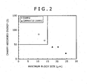
- Fig. 2 illustrates a relationship between a maximum size of the martensitic block and the Charpy absorbed energy measured by using the specimens of Examples and Comparative Examples.
- Fig. 3 illustrates a relationship between the tensile strength and the Charpy absorbed energy measured by using the specimens of Examples and Comparative Examples.
- Fig. 4 illustrates a relationship between the tensile strength and the fatigue strength measured by using the specimens of Examples and Comparative Examples.
- a maximum block size of martensite of 15 ⁇ m or less provides excellent toughness (Charpy absorbed energy).
- Fig. 3 it is found that the high strength steel for the large steel forging has excellent toughness (an impact property) even when the high strength steel for the large steel forging has higher strength (a strength of 1,050 MPa or more) than the strength of conventional steel. Generally, a material having higher strength has lower toughness.
- a high strength large steel forging having excellent strength and toughness in a balanced manner for example, a strength of 1,050 MPa or more
- Fig. 4 illustrates a relationship between the tensile strength and the fatigue strength.
- the fatigue strength of the steel forging of the present invention increases about 10% or more compared with that of the conventional steel.
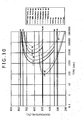
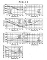
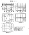
- a heat transfer and thermal stress analysis for the transformation stress in a steel by quenching was performed using general-purpose software FORGE 2009. Specific conditions are as follows. Assuming a round-bar shape, modeling was performed by using a two-dimensional axisymmetric model. In an axis direction, the modeling was performed in only a unit length, and the upper surface and the lower surface were determined to be an adiabatic state. The heat transfer and thermal stress analysis was performed in conditions that the initial temperature was uniformly set to 870°C and the temperature was cooled to around room temperature. Each material property used in the analysis is illustrated in Figs. 10 to 12 . The following analysis conditions A and B were used in the analysis.
- the analysis results in the analysis conditions A and B are illustrated in Fig. 13B .
- the analysis conditions A result in larger internal transformation stress.
- the analysis conditions B cause residual stress at a position in a ratio of depth of about 0.2.
- a structure fraction between the analysis conditions A and B enables to control whole internal stress from the surface to the center in low stress.
- a seventy-ton ingot of the steel type a having component compositions shown in Table 1 described above was casted by melting in an electric furnace and refining in a ladle.
- the ingot (70 ton) of the steel type a was hot forged by a free forging press to form round-bar-shaped forgings having a diameter of 500 mm (a radius of 250 mm), and thereafter, the round bar was cooled in the atmosphere.
- the round-bar forgings were treated with heat of 1,280°C for 3 hours, which simulated heating before RR forging.
- aging treatment for the round-bar forgings was performed (maintaining at a temperature of 650°C for 20 hours), and the round-bar-shaped forgings were cooled to room temperature.
- the quenching conditions were as follows. The round-bar forgings were heated in a heating rate of 40°C/hour and maintained at 870°C for 8 hours, and thereafter, polymer quenching was performed. Thereafter, the round-bar forgings were maintained at 580°C for 15 hours as the tempering treatment and cooled in the furnace to 350°C, and thereafter, the round-bar forgings were air-cooled to room temperature to obtain a high strength large steel forging of Reference Example 1.
- the obtained high strength large steel forging was ground so that a part of each depth in a direction from the surface to the center (25 mm, 40 mm, 70 mm, 100 mm, 130 mm, 160 mm, 190 mm, 220 mm and 250 mm) forms a surface.
- Brinell hardness HB, tensile strength (MPa), structure fraction (%), and prior austenite ( ⁇ ) grain size ( ⁇ m) at each depth were measured.
- the tensile strength of the high strength large steel forging in Reference Example 1 is a converted value calculated from the measured Brinell hardness HB in accordance with the hardness conversion table (SAE J 417). Methods for measuring and calculating Brinell hardness and a fraction of a martensitic structure are as follows. The measurement result is shown in Table 4 together with heating treatment conditions at the time of manufacture.
- the Brinell hardness was measured in accordance with JIS-Z2243 (2008).
- the fraction of martensitic structure was calculated from the measurement result of the hardness (Brinell hardness: HB) using the following formula derived from the rule of mixtures. Structures other than the martensitic structure were determined as the bainitic structure, and a bainitic structure fraction (%) was also calculated.
- HB HB M ⁇ f m x / 100 + HB B ⁇ 1 - f m x / 100
- FIG. 14A A relationship between each depth and Brinell hardness of the high strength large steel forging in the reference Example 1 is illustrated in Fig. 14A and a relationship between each depth and a fraction of a martensitic structure is illustrated in Fig. 14B .
- a high strength large steel forging of the present invention has both excellent strength and toughness, and has high fatigue strength. Consequently, the high strength large steel forging can preferably be used for large size crankshafts and intermediate shafts used for ships or power generators.
Landscapes
- Chemical & Material Sciences (AREA)
- Engineering & Computer Science (AREA)
- Materials Engineering (AREA)
- Mechanical Engineering (AREA)
- Metallurgy (AREA)
- Organic Chemistry (AREA)
- Forging (AREA)
- Heat Treatment Of Steel (AREA)
- Shafts, Cranks, Connecting Bars, And Related Bearings (AREA)
- Heat Treatment Of Articles (AREA)
Claims (2)
- Große Stahlschmiede mit hoher Festigkeit, umfassend:Zusammensetzungen, umfassend Grundzusammensetzungen, umfassend:C: 0,31 Masse-Prozent oder mehr und 0,5 Masse-Prozent oder weniger,Si: 0,02 Masse-Prozent oder mehr und 0,2 Masse-Prozent oder weniger,Mn: 0,1 Masse-Prozent oder mehr und 0,6 Masse-Prozent oder weniger,Ni: 2,6 Masse-Prozent oder mehr und 3,4 Masse-Prozent oder weniger,Cr: 0,8 Masse-Prozent oder mehr und 1,9 Masse-Prozent oder weniger,Mo: 0,25 Masse-Prozent oder mehr und 0,8 Masse-Prozent oder weniger,V: 0,05 Masse-Prozent oder mehr und 0,2 Masse-Prozent oder weniger, undAl: 0,005 Masse-Prozent oder mehr und 0,1 Masse-Prozent oder weniger, undwobei der Rest Fe und unvermeidbare Verunreinigungen umfaßt,wobei ein Gehalt an S als die unvermeidbare Verunreinigung 0,008 Masse-Prozent oder weniger beträgt, undwobei die großen Stahlschmiede mit hoher Festigkeit aus einer martensitischen Struktur oder einer gemischten Struktur von Martensit und Bainit besteht,eine Voraustenitkorngröße 19 µm oder mehr und 70 µm oder weniger beträgt, undeine Maximalblockgröße an Martensit 15 µm oder weniger beträgt und eine Minimalblockgröße an Martensit 0,5 µm oder mehr beträgt.
- Große Stahlschmiede mit hoher Festigkeit gemäß Anspruch 1, wobei eine Fraktion der martensitischen Struktur fm(x) (%), worin ein Verhältnis einer Tiefe zu einem Abstand von einer Oberfläche zu einem Zentrum als x (0 ≤ x ≤ 1) definiert ist, istfm(x) = 100, worin 0 ≤ x ≤ 0,1;104-40x ≤ fm(x) ≤ 100, worin 0,1 < x ≤ 0,15,122-160 x ≤ 100, worin 0,15 < x ≤ 0,2,230-700 x ≤ fm(x) ≤ 100, worin 0,2 < x ≤ 0,3;110-300 x ≤ fm(x) ≤ 112-40x, worin 0,3 < x ≤ 0,35;(22-20x)3 ≤ fm(x) ≤ 105-20x, worin 0,35 < x ≤0,5;(32-40x)/3 ≤ fm(x) ≤ 95, worin 0,5 < x ≤ 0,8; und0 ≤ fm(x) ≤ 95, worin 0,8 < x ≤1.
Priority Applications (1)
| Application Number | Priority Date | Filing Date | Title |
|---|---|---|---|
| PL13002083T PL2671963T3 (pl) | 2012-06-06 | 2013-04-19 | Duża odkuwka stalowa o wysokiej wytrzymałości |
Applications Claiming Priority (1)
| Application Number | Priority Date | Filing Date | Title |
|---|---|---|---|
| JP2012129381A JP5859384B2 (ja) | 2012-06-06 | 2012-06-06 | 大型高強度鍛鋼品 |
Publications (2)
| Publication Number | Publication Date |
|---|---|
| EP2671963A1 EP2671963A1 (de) | 2013-12-11 |
| EP2671963B1 true EP2671963B1 (de) | 2014-10-08 |
Family
ID=48142610
Family Applications (1)
| Application Number | Title | Priority Date | Filing Date |
|---|---|---|---|
| EP13002083.7A Active EP2671963B1 (de) | 2012-06-06 | 2013-04-19 | Grosse Stahlschmieden mit hoher festigkeit |
Country Status (5)
| Country | Link |
|---|---|
| EP (1) | EP2671963B1 (de) |
| JP (1) | JP5859384B2 (de) |
| KR (1) | KR101547015B1 (de) |
| ES (1) | ES2517523T3 (de) |
| PL (1) | PL2671963T3 (de) |
Families Citing this family (6)
| Publication number | Priority date | Publication date | Assignee | Title |
|---|---|---|---|---|
| JP6179977B2 (ja) * | 2013-05-22 | 2017-08-16 | 株式会社日本製鋼所 | 耐高圧水素環境脆化特性に優れた高強度鋼およびその製造方法 |
| JP6100156B2 (ja) * | 2013-12-19 | 2017-03-22 | 株式会社神戸製鋼所 | 鍛鋼品用高強度鋼及び鍛鋼品 |
| WO2015133470A1 (ja) * | 2014-03-05 | 2015-09-11 | 大同特殊鋼株式会社 | 時効硬化型ベイナイト非調質鋼 |
| JP2015190040A (ja) * | 2014-03-28 | 2015-11-02 | 株式会社神戸製鋼所 | 鍛鋼品用低合金鋼及びクランク軸 |
| JP2017128761A (ja) * | 2016-01-19 | 2017-07-27 | 株式会社神戸製鋼所 | 高強度鍛鋼及び大型鍛造部品 |
| JP7455112B2 (ja) * | 2019-03-25 | 2024-03-25 | 日本製鉄株式会社 | ホットスタンプ成形体 |
Family Cites Families (11)
| Publication number | Priority date | Publication date | Assignee | Title |
|---|---|---|---|---|
| JP2000212705A (ja) | 1999-01-21 | 2000-08-02 | Nippon Steel Corp | 耐焼き戻し脆性及び耐水素脆性に優れたNi系調質鋼及びその製造方法 |
| JP3896365B2 (ja) | 2000-11-22 | 2007-03-22 | 株式会社神戸製鋼所 | 高強度鍛造用鋼およびこれを用いた大型クランク軸 |
| JP3750737B2 (ja) | 2001-11-14 | 2006-03-01 | 新日本製鐵株式会社 | 非調質高強度・高靭性鍛造品の製造方法 |
| WO2005121384A2 (en) * | 2003-12-04 | 2005-12-22 | Chamberlian Manufacturing Corporation | High strength steel alloy |
| JP4332070B2 (ja) * | 2004-06-01 | 2009-09-16 | 株式会社神戸製鋼所 | 大型鍛鋼品用高強度鋼およびクランク軸 |
| JP4150054B2 (ja) * | 2006-06-21 | 2008-09-17 | 株式会社神戸製鋼所 | 鍛造用鋼およびその製造方法並びに鍛造品 |
| JP2008111146A (ja) * | 2006-10-30 | 2008-05-15 | Jfe Steel Kk | 掘削工具刃用鋼または削岩工具刃用鋼、およびその製造方法 |
| PL2141254T3 (pl) * | 2007-03-29 | 2016-10-31 | Wlewek stalowy do kucia oraz integralny wał korbowy | |
| JP2009173961A (ja) | 2008-01-22 | 2009-08-06 | Kobe Steel Ltd | 鍛造用鋼およびこれを用いて得られる鍛造品 |
| JP5262740B2 (ja) * | 2009-01-16 | 2013-08-14 | 新日鐵住金株式会社 | 浸炭時の粗大粒防止特性と疲労特性に優れた肌焼鋼とその製造方法 |
| JP5319374B2 (ja) * | 2009-04-10 | 2013-10-16 | 株式会社神戸製鋼所 | 一体型クランク軸およびその製造方法 |
-
2012
- 2012-06-06 JP JP2012129381A patent/JP5859384B2/ja active Active
-
2013
- 2013-04-19 ES ES13002083.7T patent/ES2517523T3/es active Active
- 2013-04-19 EP EP13002083.7A patent/EP2671963B1/de active Active
- 2013-04-19 PL PL13002083T patent/PL2671963T3/pl unknown
- 2013-06-05 KR KR1020130064894A patent/KR101547015B1/ko active Active
Also Published As
| Publication number | Publication date |
|---|---|
| ES2517523T3 (es) | 2014-11-03 |
| EP2671963A1 (de) | 2013-12-11 |
| KR101547015B1 (ko) | 2015-08-24 |
| JP2013253287A (ja) | 2013-12-19 |
| JP5859384B2 (ja) | 2016-02-10 |
| KR20130137101A (ko) | 2013-12-16 |
| PL2671963T3 (pl) | 2015-02-27 |
Similar Documents
| Publication | Publication Date | Title |
|---|---|---|
| JP5486634B2 (ja) | 冷間加工用機械構造用鋼及びその製造方法 | |
| TWI396755B (zh) | 高強度截斷分割用非調質鋼及截斷分割用鋼零件 | |
| EP1602742B1 (de) | Hochfester Stahl für die Herstellung von großen Schmiedestücken, insbesondere von Kurbelwellen | |
| EP2671963B1 (de) | Grosse Stahlschmieden mit hoher festigkeit | |
| EP2357262A1 (de) | Kurbelwelle und Herstellungsverfahren dafür | |
| JP5419820B2 (ja) | 熱間鍛造用圧延棒鋼または線材 | |
| WO2015050152A9 (ja) | 時効硬化性鋼 | |
| CN113348256A (zh) | 冷加工用机械结构用钢及其制造方法 | |
| KR20190028757A (ko) | 고주파 담금질용 강 | |
| JP6614393B2 (ja) | 非調質棒鋼 | |
| JP2017128795A (ja) | 鍛造用鋼及び大型鍛鋼品 | |
| EP3272896B1 (de) | Aushärtbarer stahl und verfahren zur herstellung von komponenten mit aushärtbarem stahl | |
| JP2010229475A (ja) | 高強度高靱性熱間鍛造品の製造方法 | |
| JPWO2020004060A1 (ja) | 高周波焼入れクランクシャフト及び高周波焼入れクランクシャフト用素形材の製造方法 | |
| JP6555345B2 (ja) | 熱間鍛造用鋼材 | |
| JP6390685B2 (ja) | 非調質鋼およびその製造方法 | |
| JP7270420B2 (ja) | 熱間鍛造非調質部品とその製造方法、および熱間鍛造非調質部品用鋼材 | |
| JP2013108130A (ja) | 熱間鍛造用圧延棒鋼 | |
| JP4263946B2 (ja) | 超高温熱間鍛造非調質部品とその製造方法 | |
| JP5916553B2 (ja) | コネクティングロッド用鋼及びコネクティングロッド | |
| EP3040438A1 (de) | Hochfester stahl und mit diesem hochfester stahl hergestellte kurbelwelle | |
| JP2022130746A (ja) | 非調質鍛造部品および非調質鍛造用鋼 | |
| JP5030695B2 (ja) | 破断分離性に優れる高炭素鋼およびその製造方法 | |
| JP5755965B2 (ja) | コネクティングロッド用鋼及びコネクティングロッド | |
| JP4095924B2 (ja) | 超高温熱間鍛造非調質部品とその製造方法 |
Legal Events
| Date | Code | Title | Description |
|---|---|---|---|
| PUAI | Public reference made under article 153(3) epc to a published international application that has entered the european phase |
Free format text: ORIGINAL CODE: 0009012 |
|
| AK | Designated contracting states |
Kind code of ref document: A1 Designated state(s): AL AT BE BG CH CY CZ DE DK EE ES FI FR GB GR HR HU IE IS IT LI LT LU LV MC MK MT NL NO PL PT RO RS SE SI SK SM TR |
|
| AX | Request for extension of the european patent |
Extension state: BA ME |
|
| 17P | Request for examination filed |
Effective date: 20140116 |
|
| GRAP | Despatch of communication of intention to grant a patent |
Free format text: ORIGINAL CODE: EPIDOSNIGR1 |
|
| RBV | Designated contracting states (corrected) |
Designated state(s): AL AT BE BG CH CY CZ DE DK EE ES FI FR GB GR HR HU IE IS IT LI LT LU LV MC MK MT NL NO PL PT RO RS SE SI SK SM TR |
|
| INTG | Intention to grant announced |
Effective date: 20140306 |
|
| GRAS | Grant fee paid |
Free format text: ORIGINAL CODE: EPIDOSNIGR3 |
|
| GRAA | (expected) grant |
Free format text: ORIGINAL CODE: 0009210 |
|
| AK | Designated contracting states |
Kind code of ref document: B1 Designated state(s): AL AT BE BG CH CY CZ DE DK EE ES FI FR GB GR HR HU IE IS IT LI LT LU LV MC MK MT NL NO PL PT RO RS SE SI SK SM TR |
|
| REG | Reference to a national code |
Ref country code: GB Ref legal event code: FG4D |
|
| REG | Reference to a national code |
Ref country code: CH Ref legal event code: EP Ref country code: AT Ref legal event code: REF Ref document number: 690677 Country of ref document: AT Kind code of ref document: T Effective date: 20141015 |
|
| REG | Reference to a national code |
Ref country code: ES Ref legal event code: FG2A Ref document number: 2517523 Country of ref document: ES Kind code of ref document: T3 Effective date: 20141103 |
|
| REG | Reference to a national code |
Ref country code: IE Ref legal event code: FG4D |
|
| REG | Reference to a national code |
Ref country code: DE Ref legal event code: R096 Ref document number: 602013000309 Country of ref document: DE Effective date: 20141120 |
|
| REG | Reference to a national code |
Ref country code: NO Ref legal event code: T2 Effective date: 20141008 |
|
| REG | Reference to a national code |
Ref country code: PL Ref legal event code: T3 |
|
| REG | Reference to a national code |
Ref country code: NL Ref legal event code: VDEP Effective date: 20141008 |
|
| REG | Reference to a national code |
Ref country code: AT Ref legal event code: MK05 Ref document number: 690677 Country of ref document: AT Kind code of ref document: T Effective date: 20141008 |
|
| REG | Reference to a national code |
Ref country code: LT Ref legal event code: MG4D |
|
| PG25 | Lapsed in a contracting state [announced via postgrant information from national office to epo] |
Ref country code: NL Free format text: LAPSE BECAUSE OF FAILURE TO SUBMIT A TRANSLATION OF THE DESCRIPTION OR TO PAY THE FEE WITHIN THE PRESCRIBED TIME-LIMIT Effective date: 20141008 |
|
| PG25 | Lapsed in a contracting state [announced via postgrant information from national office to epo] |
Ref country code: IS Free format text: LAPSE BECAUSE OF FAILURE TO SUBMIT A TRANSLATION OF THE DESCRIPTION OR TO PAY THE FEE WITHIN THE PRESCRIBED TIME-LIMIT Effective date: 20150208 Ref country code: LT Free format text: LAPSE BECAUSE OF FAILURE TO SUBMIT A TRANSLATION OF THE DESCRIPTION OR TO PAY THE FEE WITHIN THE PRESCRIBED TIME-LIMIT Effective date: 20141008 Ref country code: PT Free format text: LAPSE BECAUSE OF FAILURE TO SUBMIT A TRANSLATION OF THE DESCRIPTION OR TO PAY THE FEE WITHIN THE PRESCRIBED TIME-LIMIT Effective date: 20150209 |
|
| PG25 | Lapsed in a contracting state [announced via postgrant information from national office to epo] |
Ref country code: RS Free format text: LAPSE BECAUSE OF FAILURE TO SUBMIT A TRANSLATION OF THE DESCRIPTION OR TO PAY THE FEE WITHIN THE PRESCRIBED TIME-LIMIT Effective date: 20141008 Ref country code: AT Free format text: LAPSE BECAUSE OF FAILURE TO SUBMIT A TRANSLATION OF THE DESCRIPTION OR TO PAY THE FEE WITHIN THE PRESCRIBED TIME-LIMIT Effective date: 20141008 Ref country code: LV Free format text: LAPSE BECAUSE OF FAILURE TO SUBMIT A TRANSLATION OF THE DESCRIPTION OR TO PAY THE FEE WITHIN THE PRESCRIBED TIME-LIMIT Effective date: 20141008 Ref country code: CY Free format text: LAPSE BECAUSE OF FAILURE TO SUBMIT A TRANSLATION OF THE DESCRIPTION OR TO PAY THE FEE WITHIN THE PRESCRIBED TIME-LIMIT Effective date: 20141008 Ref country code: HR Free format text: LAPSE BECAUSE OF FAILURE TO SUBMIT A TRANSLATION OF THE DESCRIPTION OR TO PAY THE FEE WITHIN THE PRESCRIBED TIME-LIMIT Effective date: 20141008 Ref country code: GR Free format text: LAPSE BECAUSE OF FAILURE TO SUBMIT A TRANSLATION OF THE DESCRIPTION OR TO PAY THE FEE WITHIN THE PRESCRIBED TIME-LIMIT Effective date: 20150109 Ref country code: SE Free format text: LAPSE BECAUSE OF FAILURE TO SUBMIT A TRANSLATION OF THE DESCRIPTION OR TO PAY THE FEE WITHIN THE PRESCRIBED TIME-LIMIT Effective date: 20141008 |
|
| REG | Reference to a national code |
Ref country code: DE Ref legal event code: R097 Ref document number: 602013000309 Country of ref document: DE |
|
| PG25 | Lapsed in a contracting state [announced via postgrant information from national office to epo] |
Ref country code: DK Free format text: LAPSE BECAUSE OF FAILURE TO SUBMIT A TRANSLATION OF THE DESCRIPTION OR TO PAY THE FEE WITHIN THE PRESCRIBED TIME-LIMIT Effective date: 20141008 Ref country code: EE Free format text: LAPSE BECAUSE OF FAILURE TO SUBMIT A TRANSLATION OF THE DESCRIPTION OR TO PAY THE FEE WITHIN THE PRESCRIBED TIME-LIMIT Effective date: 20141008 Ref country code: RO Free format text: LAPSE BECAUSE OF FAILURE TO SUBMIT A TRANSLATION OF THE DESCRIPTION OR TO PAY THE FEE WITHIN THE PRESCRIBED TIME-LIMIT Effective date: 20141008 Ref country code: SK Free format text: LAPSE BECAUSE OF FAILURE TO SUBMIT A TRANSLATION OF THE DESCRIPTION OR TO PAY THE FEE WITHIN THE PRESCRIBED TIME-LIMIT Effective date: 20141008 |
|
| PLBE | No opposition filed within time limit |
Free format text: ORIGINAL CODE: 0009261 |
|
| STAA | Information on the status of an ep patent application or granted ep patent |
Free format text: STATUS: NO OPPOSITION FILED WITHIN TIME LIMIT |
|
| PG25 | Lapsed in a contracting state [announced via postgrant information from national office to epo] |
Ref country code: IT Free format text: LAPSE BECAUSE OF FAILURE TO SUBMIT A TRANSLATION OF THE DESCRIPTION OR TO PAY THE FEE WITHIN THE PRESCRIBED TIME-LIMIT Effective date: 20141008 |
|
| 26N | No opposition filed |
Effective date: 20150709 |
|
| PG25 | Lapsed in a contracting state [announced via postgrant information from national office to epo] |
Ref country code: LU Free format text: LAPSE BECAUSE OF FAILURE TO SUBMIT A TRANSLATION OF THE DESCRIPTION OR TO PAY THE FEE WITHIN THE PRESCRIBED TIME-LIMIT Effective date: 20150419 Ref country code: MC Free format text: LAPSE BECAUSE OF FAILURE TO SUBMIT A TRANSLATION OF THE DESCRIPTION OR TO PAY THE FEE WITHIN THE PRESCRIBED TIME-LIMIT Effective date: 20141008 |
|
| REG | Reference to a national code |
Ref country code: IE Ref legal event code: MM4A |
|
| REG | Reference to a national code |
Ref country code: FR Ref legal event code: ST Effective date: 20151231 |
|
| PG25 | Lapsed in a contracting state [announced via postgrant information from national office to epo] |
Ref country code: FR Free format text: LAPSE BECAUSE OF NON-PAYMENT OF DUE FEES Effective date: 20150430 Ref country code: SI Free format text: LAPSE BECAUSE OF FAILURE TO SUBMIT A TRANSLATION OF THE DESCRIPTION OR TO PAY THE FEE WITHIN THE PRESCRIBED TIME-LIMIT Effective date: 20141008 |
|
| PG25 | Lapsed in a contracting state [announced via postgrant information from national office to epo] |
Ref country code: IE Free format text: LAPSE BECAUSE OF NON-PAYMENT OF DUE FEES Effective date: 20150419 |
|
| REG | Reference to a national code |
Ref country code: CH Ref legal event code: PL |
|
| PG25 | Lapsed in a contracting state [announced via postgrant information from national office to epo] |
Ref country code: MT Free format text: LAPSE BECAUSE OF FAILURE TO SUBMIT A TRANSLATION OF THE DESCRIPTION OR TO PAY THE FEE WITHIN THE PRESCRIBED TIME-LIMIT Effective date: 20141008 |
|
| PG25 | Lapsed in a contracting state [announced via postgrant information from national office to epo] |
Ref country code: CH Free format text: LAPSE BECAUSE OF NON-PAYMENT OF DUE FEES Effective date: 20160430 Ref country code: LI Free format text: LAPSE BECAUSE OF NON-PAYMENT OF DUE FEES Effective date: 20160430 |
|
| PG25 | Lapsed in a contracting state [announced via postgrant information from national office to epo] |
Ref country code: HU Free format text: LAPSE BECAUSE OF FAILURE TO SUBMIT A TRANSLATION OF THE DESCRIPTION OR TO PAY THE FEE WITHIN THE PRESCRIBED TIME-LIMIT; INVALID AB INITIO Effective date: 20130419 Ref country code: BG Free format text: LAPSE BECAUSE OF FAILURE TO SUBMIT A TRANSLATION OF THE DESCRIPTION OR TO PAY THE FEE WITHIN THE PRESCRIBED TIME-LIMIT Effective date: 20141008 |
|
| PG25 | Lapsed in a contracting state [announced via postgrant information from national office to epo] |
Ref country code: TR Free format text: LAPSE BECAUSE OF FAILURE TO SUBMIT A TRANSLATION OF THE DESCRIPTION OR TO PAY THE FEE WITHIN THE PRESCRIBED TIME-LIMIT Effective date: 20141008 |
|
| PG25 | Lapsed in a contracting state [announced via postgrant information from national office to epo] |
Ref country code: BE Free format text: LAPSE BECAUSE OF FAILURE TO SUBMIT A TRANSLATION OF THE DESCRIPTION OR TO PAY THE FEE WITHIN THE PRESCRIBED TIME-LIMIT Effective date: 20141008 |
|
| GBPC | Gb: european patent ceased through non-payment of renewal fee |
Effective date: 20170419 |
|
| PG25 | Lapsed in a contracting state [announced via postgrant information from national office to epo] |
Ref country code: GB Free format text: LAPSE BECAUSE OF NON-PAYMENT OF DUE FEES Effective date: 20170419 |
|
| PG25 | Lapsed in a contracting state [announced via postgrant information from national office to epo] |
Ref country code: SM Free format text: LAPSE BECAUSE OF FAILURE TO SUBMIT A TRANSLATION OF THE DESCRIPTION OR TO PAY THE FEE WITHIN THE PRESCRIBED TIME-LIMIT Effective date: 20141008 |
|
| PG25 | Lapsed in a contracting state [announced via postgrant information from national office to epo] |
Ref country code: MK Free format text: LAPSE BECAUSE OF FAILURE TO SUBMIT A TRANSLATION OF THE DESCRIPTION OR TO PAY THE FEE WITHIN THE PRESCRIBED TIME-LIMIT Effective date: 20141008 |
|
| PG25 | Lapsed in a contracting state [announced via postgrant information from national office to epo] |
Ref country code: AL Free format text: LAPSE BECAUSE OF FAILURE TO SUBMIT A TRANSLATION OF THE DESCRIPTION OR TO PAY THE FEE WITHIN THE PRESCRIBED TIME-LIMIT Effective date: 20141008 |
|
| PGFP | Annual fee paid to national office [announced via postgrant information from national office to epo] |
Ref country code: CZ Payment date: 20230329 Year of fee payment: 11 |
|
| P01 | Opt-out of the competence of the unified patent court (upc) registered |
Effective date: 20230523 |
|
| PG25 | Lapsed in a contracting state [announced via postgrant information from national office to epo] |
Ref country code: CZ Free format text: LAPSE BECAUSE OF NON-PAYMENT OF DUE FEES Effective date: 20240419 |
|
| PG25 | Lapsed in a contracting state [announced via postgrant information from national office to epo] |
Ref country code: CZ Free format text: LAPSE BECAUSE OF NON-PAYMENT OF DUE FEES Effective date: 20240419 |
|
| PGFP | Annual fee paid to national office [announced via postgrant information from national office to epo] |
Ref country code: PL Payment date: 20250314 Year of fee payment: 13 |
|
| PGFP | Annual fee paid to national office [announced via postgrant information from national office to epo] |
Ref country code: FI Payment date: 20250421 Year of fee payment: 13 |
|
| PGFP | Annual fee paid to national office [announced via postgrant information from national office to epo] |
Ref country code: DE Payment date: 20250305 Year of fee payment: 13 |
|
| PGFP | Annual fee paid to national office [announced via postgrant information from national office to epo] |
Ref country code: ES Payment date: 20250507 Year of fee payment: 13 |
|
| PGFP | Annual fee paid to national office [announced via postgrant information from national office to epo] |
Ref country code: NO Payment date: 20250409 Year of fee payment: 13 |