EP2670587B1 - Tablettenpresse - Google Patents
Tablettenpresse Download PDFInfo
- Publication number
- EP2670587B1 EP2670587B1 EP12702311.7A EP12702311A EP2670587B1 EP 2670587 B1 EP2670587 B1 EP 2670587B1 EP 12702311 A EP12702311 A EP 12702311A EP 2670587 B1 EP2670587 B1 EP 2670587B1
- Authority
- EP
- European Patent Office
- Prior art keywords
- die
- tablet
- press
- tablet press
- actuator
- Prior art date
- Legal status (The legal status is an assumption and is not a legal conclusion. Google has not performed a legal analysis and makes no representation as to the accuracy of the status listed.)
- Active
Links
Images

Classifications
-
- B—PERFORMING OPERATIONS; TRANSPORTING
- B30—PRESSES
- B30B—PRESSES IN GENERAL
- B30B11/00—Presses specially adapted for forming shaped articles from material in particulate or plastic state, e.g. briquetting presses, tabletting presses
-
- A—HUMAN NECESSITIES
- A61—MEDICAL OR VETERINARY SCIENCE; HYGIENE
- A61J—CONTAINERS SPECIALLY ADAPTED FOR MEDICAL OR PHARMACEUTICAL PURPOSES; DEVICES OR METHODS SPECIALLY ADAPTED FOR BRINGING PHARMACEUTICAL PRODUCTS INTO PARTICULAR PHYSICAL OR ADMINISTERING FORMS; DEVICES FOR ADMINISTERING FOOD OR MEDICINES ORALLY; BABY COMFORTERS; DEVICES FOR RECEIVING SPITTLE
- A61J3/00—Devices or methods specially adapted for bringing pharmaceutical products into particular physical or administering forms
- A61J3/06—Devices or methods specially adapted for bringing pharmaceutical products into particular physical or administering forms into the form of pills, lozenges or dragees
-
- B—PERFORMING OPERATIONS; TRANSPORTING
- B30—PRESSES
- B30B—PRESSES IN GENERAL
- B30B11/00—Presses specially adapted for forming shaped articles from material in particulate or plastic state, e.g. briquetting presses, tabletting presses
- B30B11/02—Presses specially adapted for forming shaped articles from material in particulate or plastic state, e.g. briquetting presses, tabletting presses using a ram exerting pressure on the material in a moulding space
- B30B11/04—Presses specially adapted for forming shaped articles from material in particulate or plastic state, e.g. briquetting presses, tabletting presses using a ram exerting pressure on the material in a moulding space co-operating with a fixed mould
-
- A—HUMAN NECESSITIES
- A61—MEDICAL OR VETERINARY SCIENCE; HYGIENE
- A61K—PREPARATIONS FOR MEDICAL, DENTAL OR TOILETRY PURPOSES
- A61K9/00—Medicinal preparations characterised by special physical form
- A61K9/20—Pills, tablets, discs, rods
- A61K9/2095—Tabletting processes
-
- B—PERFORMING OPERATIONS; TRANSPORTING
- B30—PRESSES
- B30B—PRESSES IN GENERAL
- B30B11/00—Presses specially adapted for forming shaped articles from material in particulate or plastic state, e.g. briquetting presses, tabletting presses
- B30B11/005—Control arrangements
-
- B—PERFORMING OPERATIONS; TRANSPORTING
- B30—PRESSES
- B30B—PRESSES IN GENERAL
- B30B11/00—Presses specially adapted for forming shaped articles from material in particulate or plastic state, e.g. briquetting presses, tabletting presses
- B30B11/02—Presses specially adapted for forming shaped articles from material in particulate or plastic state, e.g. briquetting presses, tabletting presses using a ram exerting pressure on the material in a moulding space
- B30B11/025—Presses specially adapted for forming shaped articles from material in particulate or plastic state, e.g. briquetting presses, tabletting presses using a ram exerting pressure on the material in a moulding space whereby the material is transferred into the press chamber by relative movement between a ram and the press chamber
-
- B—PERFORMING OPERATIONS; TRANSPORTING
- B30—PRESSES
- B30B—PRESSES IN GENERAL
- B30B15/00—Details of, or accessories for, presses; Auxiliary measures in connection with pressing
-
- B—PERFORMING OPERATIONS; TRANSPORTING
- B30—PRESSES
- B30B—PRESSES IN GENERAL
- B30B15/00—Details of, or accessories for, presses; Auxiliary measures in connection with pressing
- B30B15/02—Dies; Inserts therefor; Mounting thereof; Moulds
- B30B15/028—Loading or unloading of dies, platens or press rams
-
- B—PERFORMING OPERATIONS; TRANSPORTING
- B30—PRESSES
- B30B—PRESSES IN GENERAL
- B30B15/00—Details of, or accessories for, presses; Auxiliary measures in connection with pressing
- B30B15/26—Program-control arrangements
-
- B—PERFORMING OPERATIONS; TRANSPORTING
- B30—PRESSES
- B30B—PRESSES IN GENERAL
- B30B15/00—Details of, or accessories for, presses; Auxiliary measures in connection with pressing
- B30B15/30—Feeding material to presses
-
- B—PERFORMING OPERATIONS; TRANSPORTING
- B30—PRESSES
- B30B—PRESSES IN GENERAL
- B30B15/00—Details of, or accessories for, presses; Auxiliary measures in connection with pressing
- B30B15/32—Discharging presses
-
- G—PHYSICS
- G01—MEASURING; TESTING
- G01N—INVESTIGATING OR ANALYSING MATERIALS BY DETERMINING THEIR CHEMICAL OR PHYSICAL PROPERTIES
- G01N1/00—Sampling; Preparing specimens for investigation
- G01N1/28—Preparing specimens for investigation including physical details of (bio-)chemical methods covered elsewhere, e.g. G01N33/50, C12Q
-
- G—PHYSICS
- G01—MEASURING; TESTING
- G01N—INVESTIGATING OR ANALYSING MATERIALS BY DETERMINING THEIR CHEMICAL OR PHYSICAL PROPERTIES
- G01N3/00—Investigating strength properties of solid materials by application of mechanical stress
- G01N3/08—Investigating strength properties of solid materials by application of mechanical stress by applying steady tensile or compressive forces
-
- G—PHYSICS
- G01—MEASURING; TESTING
- G01N—INVESTIGATING OR ANALYSING MATERIALS BY DETERMINING THEIR CHEMICAL OR PHYSICAL PROPERTIES
- G01N2203/00—Investigating strength properties of solid materials by application of mechanical stress
- G01N2203/02—Details not specific for a particular testing method
- G01N2203/026—Specifications of the specimen
- G01N2203/0284—Bulk material, e.g. powders
Definitions
- the present invention relates to a tablet press and more particularly, although not exclusively, to a press for use in producing pharmaceutical tablets.
- the large-scale production of tablets typically involves the use of tablet punches which operate to compact a volume of powder located in a die.
- the powder in the die is held between opposing punches which move together by a predetermined distance of travel to produce a tablet of controlled thickness within a die of known geometry. This is such that the formed tablet has a known or determinable density according to the die geometry and volume of powder used but there is no direct control of the force applied to the tablet during the compaction process.
- a conventional machine comprises a rotary press/punch configuration and a settable gearing mechanism so as to apply compaction pressure in a generally sinusoidal profile.
- Tabletting machines may be configured for either batch runs or continuous operation according to the above principles. In either case, the desire for repeatability in the compression process generally dictates that a rotary punch actuation configuration is used for large scale manufacturing.
- DE296 08 808 U1 describes a press for making tablets from a powdered substance.
- the press has a base plate for receiving a mold, a pneumatic cylinder whose piston rod engages an upper part of the mold and an electronic control unit to control the pressing process.
- CN 2480148 Y discloses an automatic tablet press machine where powdered cement is transported into a device to test via an electric motor and automatic control device.
- JP S64 27795 discloses an electric motor screw press device for powder material according to the preamble of claim 1.
- a motor rotates two ball shafts and a sliding plate is descended along the ball shafts via ball nuts such that an upper die compresses powder material inside a lower die.
- the reaction force against the pressure of the upper die acts on pistons inside hydraulic cylinders so that the reaction force on each ball screw can be displayed.
- the present invention may be considered to derive from the general principle of providing a relatively small and low cost tablet press that offers improved user control over individual or relatively small batch production of tablets.
- the arrangement of the present invention may provide for a compact and lightweight machine which can be used to manufacture individual or small numbers of tablets.
- the tablet press is portable.
- the tablet press may weigh less than, for example, 50 kg and preferably less than 30 kg.
- the tablet press may be of a size and shape such that it can be moved or carried by one person.
- the actuator comprises an electric motor, which may comprise a DC motor.
- the motor may comprise a brushed motor.
- the actuator comprises an electrical or electronic controller, such as a microcontroller, which is able to determine and/or modify pressing cycle parameters in accordance with a desired tablet characteristic.
- the controller may allow for digital control of the motor, which may be achieved using one or more of a number of control parameters such as force or displacement.
- the actuator may be controlled by the controller based upon a desired value of an operation variable input by a user.
- the combination of an electronic, or digital, controller and an electric actuator is particularly beneficial in providing for a highly configurable/controllable and portable, desktop press.
- the controller may control the motor to undergo a single pressing cycle, or a small number of pressing cycles, in response to a user input.
- the user input may comprise a desired applied load to the powder and/or a desired tablet thickness.
- the desired tablet characteristic may be input by an operator.
- the pressing cycle or actuation parameter determined by the controller may comprise any, or any combination, of a pressing load, a distance of travel or end position of the press member, a duration of pressing and/or a speed of travel of the press member.
- The, or each, pressing cycle may comprise a pressing stage, during which a tablet is formed, and a tablet ejection stage.
- the pressing stage may comprise movement of the press member into the actuated condition followed by retraction there-from. The retraction may be to a return or at-rest condition.
- the ejection stage may comprise actuation of the press member into the die such that it contacts the tablet formed therein so as to dislodge the tablet from the die.
- the ejection stage may comprise opening a floor portion of the die for ejection of the tablet.
- the actuator may drive the press member at a variable speed.
- the speed of press member actuation may be controlled by the controller, for example by application of a constant speed or fixed acceleration/deceleration profile, or else by dynamic speed control, for example based upon one or more sensed operational parameters, such as the load applied by the press member.
- the press member may move at a first speed during a first portion of the pressing cycle, which portion typically comprises a pre- or post-compaction movement of the press member, and a second speed at a second portion of the pressing cycle, which typically comprises a compaction phase of the pressing cycle, wherein the first and second speeds may be different.
- the press member may be spaced from the die and/or powder in the first portion.
- the second portion may comprise a compaction phase of the press cycle, during which the press member enters the die and/or contacts the powder.
- the controller may control actuation of the press member at the second speed upon determination that the press member is at or adjacent the die opening.
- the actuator may be arranged to drive the press member in a first, or compaction, direction and a second, or reverse, direction.
- the actuator may drive the press member in the first direction up to a predetermined condition.
- the condition may be a stop condition and may be determined by the location of the press member and/or load applied by, or to, the press member. The location of the press member may be determined relative to a datum point and/or the position of the die.
- the controller may control the actuator to cease actuation of the press member in the first direction.
- the actuator may cease actuation for a predetermined time and/or enter a reverse operation mode in which the press member is moved in a reverse direction.
- the tablet press may comprise a load sensor.
- the load sensor may comprise a load cell.
- the load sensor may be arranged in the force path between the actuator and press member.
- the load sensor may be located in the force path between the spacer and the press member.
- the controller may record the maximum load on the press member in the actuation condition or during a compaction cycle.
- the controller may log the load on the press member at a plurality of times during a compaction cycle.
- a pair of spaced, generally parallel spacers may be provided, typically with the press member being arranged there-between.
- the controller may receive or determine the location or travel distance of the press member.
- the controller may receive or determine the load on the press member.
- the controller may record data for the press member position and/or load at predetermined time intervals or positions. The recorded data or a part thereof may be output on a graphic display, for example on a screen and/or on a printout. Recorded data may be plotted as a graphical output.
- the controller may also determine the ejection load required to dislodge or eject the tablet from the die once formed.
- the base and/or die comprises a guide member, such as, for example, a funnel or chute.
- the guide member may depend from an open end of the die.
- the die may comprise a die floor portion and an intermediate member having a recess or bore therein for reception of powder in use.
- the intermediate member may comprise an upstanding, typically tubular, member or portion of the die.
- the die floor and intermediate member may cooperate to define a die formation having a closed end.
- the die floor portion and intermediate member may be arranged for selective relative movement.
- the die floor may comprise a slider member arranged for movement relative to the intermediate member between a compaction condition and a tablet ejection condition.
- the die floor may comprise an opening which is offset from the intermediate member recess in the compaction condition and which is aligned with the intermediate member recess in the ejection condition.
- the controller may comprise one or more processors in the base.
- the controller may comprise machine readable code in the form of one or more modules.
- the machine readable code may comprise software or firmware instructions for control of the actuator.
- the tablet press may comprise one or more ports or electrical connectors for connection with a separate control or processing means, which may comprise a personal computer or other conventional processing device.
- the tablet press itself comprises a controller for controlling basic operation of the press and further functionality and/or control is provided by connection to an external processing means running bespoke machine readable code.
- the further functionality may comprise reporting or control tools.
- the tablet press may comprise a user interface.
- the user interface may have one or more user input keys and/or a display screen.
- the controller may operate under an open or closed loop in dependence on the sensed operating conditions, such as the load or position of the press member.
- the press member is arranged such that its free end in use defines a surface of the produced tablet.
- the tablet may be formed according to a shape defined by the die floor, the intermediate member recess and the press member.
- the present invention is particularly useful for research work or other small scale manufacture since it allows tablets to be produced individually or in small numbers, wherein the compaction load and/or dimensions of each tablet are known upon production. This is particularly useful when testing or evaluating different tablet formulations and compaction loads to determine a setup required to achieve a tablet having suitable mechanical properties. Such properties can affect the mechanical strength or hardness of the tablet as well as the tablet uniformity and the rate at which a tablet can disintegrate/dissolve in use.
- Embodiments of the present invention described below allow for the provision of a tablet press which is portable.
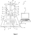
- FIG 1 there is shown a tablet press 10 having a base 12, which comprises a base housing 14.
- a lower region of the base 12 has feet 16 arranged to support the weight of the tablet press 10 on a suitable surface 18 for use.
- the pillars 20 have a lower end which is located within the base housing 14 and an opposing upper end which protrudes above the base housing 14.
- the pillars 20 are arranged generally vertically when the feet 16 are on a horizontal surface 18.
- a support member 22 which extends between the pillars and which is arranged generally perpendicular to the longitudinal axes of the pillars.
- a press member which is referred to herein as punch 24.
- the punch 24 depends from the support member 22 at a location between, and typically equidistant from, the pillars 20.
- the punch 24 is elongate in form and extends towards the base 12 in a direction which is generally parallel with the pillars 20.
- the punch is generally cylindrical in shape although other shapes are possible including oval, square or other shapes to which tablets are conventionally formed.
- the punch has a free end 25 which is blunt.
- the free end 25 defines in part the shape of a tablet formed by the tablet press 10 in use. Accordingly the free end may be flat or curved in a desired tablet profile. In this regard, it may be possible to provide the punch with interchangeable end sections to suit different tablet shapes. In such embodiments, the die shape will typically be interchangeable to correspond with the punch shape.
- the support member 22 comprises a load sensor in the form of a load cell 26 arranged intermediate the punch 24 and the remainder of the support member.
- the punch 24, at its fixed end, may be mounted at or on the load cell 26, which may itself be mounted in a correspondingly shaped recess or formation in the support member.
- the load sensor may be located in an alternative position, such as, for example, in the base 12 or elsewhere in the force path between the motor and base.
- the support pillars 20 terminate at their lower ends within the base housing 14.
- an electric motor assembly 28 which, in this embodiment, comprises a conventional brushed DC motor.
- motor may be used, such as, for example, brushless DC motors, including stepper motors.
- An electric motor is a suitable drive means for the tablet press due to the range of travel required by the pillars 20.
- electromechanical drive or actuator could be considered provided they can allow for suitable linear displacement of the pillars 20 in use.
- feedback to the motor is provided, for example using a linear variable displacement transformer (LVDT)
- the motor assembly 28 is shown schematically in Figure 1 in cooperation with the pillars 20.
- Various configurations for uniformly driving the pillars 20 by the motor assembly 28 may be employed.
- the lower ends of the pillars 20 may be connected to a common cross member (not shown) and the motor 28 may be arranged to actuate the cross member such that the pillars are simultaneously driven by a single motor.
- the motor assembly 28 further comprises a linear servo amplifier which powers the motor.
- a digital encoder is also provided for the control of the motor.
- the encoder is an integral part of the motor assembly 28 within the base housing 14.
- a user interface 30 is provided, for example on a panel of the base housing 14, and comprises a display screen 32 and a plurality of keys 32 in the form of a keypad.
- the keys allow for alphanumeric character entry by a user in a conventional manner.
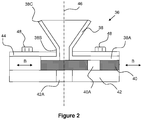
- a die assembly 36 comprising a die member 38 and a die floor or base 40.
- the die member and die floor are held in position against a plate 42 on the base 12 by retaining formations 44.
- the members 40-44 are elongate in form and sectional profile of those members is generally constant. That is to say, the end profile shown in Figure 1 extends in a direction into the page.
- the die assembly and the pillars and punch 24 are generally symmetrical about axis 46 which is also the direction of travel of the punch 24 in use. In the orientation shown, the axis 46 is generally vertically aligned.
- a force path can be defined between the motor assembly 28, the pillars 20, the support member 22, including the load cell 26, and punch 24. Accordingly a load applied by the motor can be communicated to the punch 24 such that the punch applies a load to powder in the die. Any reaction to the applied load experience by the punch 24 can be recorded by the load cell 26.
- the motor 28 and load cell 26 are typically arranged to allow for a load of up to approximately 500 kg or 4900 N.
- the die member 38 has a first portion 38A which is shaped for location of the die member 38 relative to the die floor 40 and base housing 14.
- the first portion 38A in cross section generally takes the form of an inverted channel or U-shaped formation.
- the channel side walls rest on the plate 42 or the base housing 14 directly so as to define an open ended channel.
- the die floor 40 is insertable in the channel of the first portion between the channel side walls.
- a second portion 38B of the die member depends upwardly from the first portion 38A and is shaped to define the die in which a tablet is formed in use.
- the second portion has an upstanding wall which is generally tubular or toroidal in shape and has a central bore aligned with axis 46, into which powder can be inserted.
- a third portion 38C of the die member depends upwardly from the second member and comprises an open ended funnel formation which is aligned with the common axis 46.
- the funnel 38C has an upwardly facing open mouth which tapers towards a narrow opening which leads into the bore of the die section 38B.
- the first portion 38A When assembled for use, the first portion 38A is positioned relative to plate 42 and beneath the retaining formations 44 such that the die 38B is aligned with the axis 46.
- the die floor member 40 is inserted into the channel of the first portion 38A such that it closes the die at its lower end.
- the die floor member may be considered to act as a closure.
- the die floor 40 is elongate in form and has an opening 40A part way along its length.
- the opening 40A takes the form of a through hole.
- the opening 40A has a width or diameter which is slightly larger than that of the die 38B.
- the opening 40 A is offset from the die such that the die is closed at its lower end.
- the lower plate 42 also has an opening or recess 42A therein.
- the recess 42A is the same or slightly wider than the opening 40A in the die floor 40.
- the recess 42A is aligned with the die axis 46 but isolated there-from by the die floor 40 in the condition shown in Figure 2 .
- One of more fixing members such as for example through bolts or screws 48 pass through some or all of the components of the die assembly 36 in order to hold the assembly securely in place for use.
- the fixing members may be received in a corresponding formation within the base housing 14, such as, for example, a threaded bore (not shown).
- a powder is poured or otherwise inserted into the funnel 38C such that it falls into the die 38B and rests on the die floor member 40.
- conventional means such as a powder pipette may be used to insert a measured amount of powder into the die.
- the pillars are then actuated by the motor 28 to displace the punch 24 downward towards the die member 38 in the direction of the common axis 46.
- the punch end 25 enters the die and applies a load to the powder therein so as to compact the powder into a tablet.
- the use of spaced pillars helps to ensure accurate axial displacement of the punch 24.
- the motor assembly actuates the pillars 20 in the reverse direction such that the punch 24 is retracted clear of the die.
- the die floor 40 is then moved in a linear manner in the direction of arrow B in Figure 2 , such that the opening 40B is aligned with the die axis 46, beneath the die.
- the die floor is typically manually actuated but this process may be driven and/or automated in alternative embodiments.
- the tablet can then be ejected by applying an ejection force to the tablet such that it is dislodged from the die and falls into opening 40A.
- the ejection force can be applied by a second actuation of the punch 24 by the motor 28.
- a separate ejection mechanism can be provided as necessary.
- the tablet falls through the die floor 40 and is caught in the recess 42A in the plate 42.
- the plate 42 can later be slid out from beneath the die assembly to remove the tablet there-from.
- Such an arrangement is considered beneficial since it allows a tablet, once formed to be held in an enclosed space until access is required by the user. This may allow the tablet to remain enclosed, for example, whilst further tablets are being formed or else whilst other steps are undertaken before access to the tablet is required.
- the plate 40 may not have the recess 42A and the die base opening 40A may be used to hold the tablet until access is required by a user.
- the member 40 may thus be slid in a reverse direction to access the tablet in the opening 40A.
- the tablet press 10 comprises one or more processors, typically in the form of a microchip, and a data store or memory for controlling actuation of the punch by the motor 28 in accordance with user inputs.
- the tablet press further comprises means for establishing a data connection with a separate computing means.
- an electrical connector 50 in the tablet press 10 is connected by a lead 52 to a laptop 54.
- a wireless data link may be established in different embodiments by providing the tablet press with conventional wireless data transfer hardware, such as may be required for data transmission/reception by radio using, for example Wi-Fi, GSM, 3G, Bluetooth or other communication standards.
- the operating system for the tablet press comprises two parts.
- the processor in the tablet press 10 itself is provided with machine-readable code in the form of firmware.
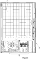
- the PC 54 is provided with software that controls the display of an on-screen user interface, an example of which is shown in Figure 3 .
- the tablet press then initialises by actuating the motor 28 such that the punch is moved to a fully retracted position. This position serves as the datum position for the machine. Any settings stored in the memory from a previous instance of use are retrieved from the memory.
- tablet pressing parameters can be set at 55 or altered using the user interface 56 on the PC.
- the parameters that are required for entry or upload by a user comprise the following:
- the above data and or instructions are entered by the user using the buttons and alphanumeric character entry boxes in the region 58 of the graphical user interface 56.
- the position of the bottom of the die is established by the firmware at stage 60.
- the insertion of different dies into the press may change this parameter.
- the determination of the location of the floor of the die relative to the datum position at 60 is achieved by placing the empty die in the machine and starting the 'new size' procedure.
- the firmware controls actuation of the punch 24 downwards until it touches the die floor member 40.
- the distance of travel and/or position of the die floor 40 relative to the datum position is stored.
- the punch 24 then retracts out of the die 38.
- the die is now loaded with powder by a user. This may be achieved by removing the die 38 or die assembly 36 and inserting powder therein using a suitable dispensing device. Alternatively this may be achieved in-situ. Once the die and powder therein is correctly positioned in the tablet press 10, the compaction stage can begin.
- the compaction is started from the PC.
- the firmware is able to calculate a number of positions at point 62 in Figure 4 , comprising:
- a tablet description (identifier) can be input by the user via the PC interface. This is shown on exported reports.
- the determined parameters are sent back to the PC by the tablet press firmware at 66, along with an indication that the compaction is starting.
- the firmware then controls operation of the motor 28 in conjunction with the digital encoder such that the punch 24 moves downwards at full speed until the compaction speed position (as calculated at stage 62) is reached. This position is determined by control loop 68, at which point the firmware controls the change in operation of the motor 28 to operate the punch at the compaction speed, which is constant for the compaction phase of the process.
- the punch 24 continues its downward movement such that it comes into contact with powder in the die.
- the change to compaction speed also triggers a signal from the tablet press to the PC such that the PC software will start plotting a graph of load against position for the punch in window 72 of the user interface 56.
- the load reading is taken from the load cell 26 and the position is determined by the angular position of the motor in accordance with the digital encoder.
- Compaction continues under the control loop 74 until either: the stop position (calculated in (i) above) is reached, when in the 'fixed thickness' mode; or, the target load (set in b above) is reached, when in the 'fixed load' mode. In either mode, the compaction will be aborted if the load cell is overloaded.
- the punch then stops.
- the punch may be held for a predetermined period at this position.
- the motor is controlled to retract the punch at compaction speed for a predetermined distance, such as, for example 2mm.
- Graph plotting then ends.
- the motor then actuates the punch in the retraction direct at full speed to the datum position at 76.
- the user is given the option to eject the tablet from the die at 78. If this is manually declined by the user, the routine ends and the firmware returns to a ready condition for a further compaction.
- the user slides the die floor 40 to its open condition such that the opening 40A is below the die, and clicks a button in the PC user interface to commence the ejection procedure.
- the punch initially runs downward at full speed at stage 80, until the compaction speed position is reached. The punch then continues at compaction speed at stage 82.
- This motor control sequence is similar to that of the compaction itself and is not repeated here for conciseness.
- the controller instead determines whether the punch end 25 has reach end has reached the location of the bottom of the die (i.e. the location at which the floor member 40 was previously present). Once the bottom of the die is reached, the punch reverses to the return position.
- the tablet press and associated firmware now return to a ready condition in which the tablet press is able to start the next compaction, or for settings to be altered.
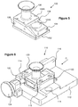
- FIG. 5 there is shown a further embodiment of a die assembly 100 for use in conjunction with the base 12 of the tablet press.
- the die assembly 100 is substantially as described above in relation to the die 36 of Figure 2 .
- the base plate 102 of the assembly is substantially planar in form and devoid of any opening for receipt of a tablet once formed.
- the intermediate member 104 in this embodiment comprises a slider block or drawer member having an opening 104A therein, similar to that described above in relation to Figure 2 .
- the die member 106 in this embodiment has a first part 106A which is mounted to side walls 108 positioned on either side of the slider member 104.
- the combined side walls 108, the base plate 102 and the mounting portion 106A of the die provide an enclosure for the slider 104, through which the slider can be actuated, typically manually in forward and reverse directions between positions in which the opening 104A is respectively aligned and offset with the die.
- the enclosure is a close fit about the slider 104 and thus constrains the motion of the slider to a linear motion only.
- FIG 6 there are shown further details of a die mounting assembly 110 that may be used to mount the dies of either Figures 2 or 5 to the base 12, and typically to an upper surface of the housing 14 thereof.
- the mounting assembly 110 comprises a supporting member 112 which generally takes the form of a block or plate-like member having a planar/flat upper surface on which the die assembly 100 is mounted for use.
- the supporting member 112 is mounted on the upper portion of the base 12 of Figure 1 for use and provides a stable platform for location of the die relative to the press member 24.
- the supporting member has through holes 114 arranged to accommodate the pillars 20.
- a pair of spaced retaining walls 116 and 118 are upstanding from the member 112 and are aligned (i.e. extending in parallel directions).
- the wall 118 is purposely shorter than the wall 116 for ease of loading the die assembly.
- the die assembly 100 of Figure 5 is a close fit between the retaining walls 116 and 118 to ensure accurate positioning of the die.
- Each of the retaining walls comprise a flange formation 120 spaced from the upper surface of the supporting member 112 by a distance which is substantially equal to the depth of the body of the die assembly. Accordingly the flanges 120 serve to retain the die assembly correctly against the upper surface of support 112 such that the height of the die relative to the support (and the base of the press) is fixed.
- the die assembly 100 can slide into position between the retaining walls 116 and 118 in the direction of arrow C, such that its height and lateral position is fixed relative to the base 12 and press member 24.
- a stop member 122 is provided at one end of the channel defined by the retaining walls.
- the stop member is adjustable by way of a knob 124 such that the longitudinal position of the die assembly can be manually altered to align the die beneath the press member 24 for use.
- the stop member preferably comprises a threaded shaft portion which is received in a correspondingly threaded bore, for example in the manner of a thumb screw.
- Figures 5 and 6 show the die assembly in a compaction condition with the recess 104A offset from the die.
- the slider can be actuated to a position in which the recess 104A is beneath the die, thereby allowing ejection of the tablet into the recess.
- a reverse sliding actuation of the slider 104 allows removal of the tablet by the operator whereby the ejected tablet contained in the recess 104A is exposed for removal of the tablet.
- the base plate 102 has a greater length than the die mounting portion 106A to allow the opening 104A to slide out from beneath the die.
- the present invention is particularly advantageous since individual or small batches of tablets can be produced under known compaction parameters which have been entered by a user.
- the compaction parameters for each tablet produced can be individually set by a user.
Landscapes
- Mechanical Engineering (AREA)
- Engineering & Computer Science (AREA)
- Health & Medical Sciences (AREA)
- Chemical & Material Sciences (AREA)
- Life Sciences & Earth Sciences (AREA)
- General Health & Medical Sciences (AREA)
- Medicinal Chemistry (AREA)
- Pathology (AREA)
- Analytical Chemistry (AREA)
- Immunology (AREA)
- General Physics & Mathematics (AREA)
- Biochemistry (AREA)
- Physics & Mathematics (AREA)
- Animal Behavior & Ethology (AREA)
- Public Health (AREA)
- Pharmacology & Pharmacy (AREA)
- Veterinary Medicine (AREA)
- Epidemiology (AREA)
- Medical Preparation Storing Or Oral Administration Devices (AREA)
- Processing And Handling Of Plastics And Other Materials For Molding In General (AREA)
- Press Drives And Press Lines (AREA)
- Casting Or Compression Moulding Of Plastics Or The Like (AREA)
- Medicinal Preparation (AREA)
Claims (12)
- Tablettenpresse (10), umfassend:eine Basis (12);ein Presselement (24), das durch einen Abstandshalter (20) relativ zu der Basis (12) gehalten wird,wobei die Basis (12) eine Form (38B) zur Aufnahme eines Pulvers in Gebrauch umfasst, wobei der Abstandshalter (20) von der Basis (12) abhängt und unter der Steuerung eines Aktors (28) relativ dazu bewegbar ist;und eine elektronische Steuerung, die zur Steuerung des Aktors (28) angeordnet ist,wobei das Presselement (24) umkehrbar zwischen einem Ruhezustand, in dem das Presselement (24) von der Form (38B) beabstandet ist, und einem betätigten Zustand, in dem sich das Presselement (24) in der Form (38B) befindet und eine Last auf ein Pulver darin ausübt, betätigbar ist; wobeider Aktor (28) einen Elektromotor umfasst, und dassdie Tablettenpresse ferner einen oder mehrere Sensoren (26) zum Bestimmen von Momentanwerten von einer oder mehreren Betriebsvariablen in Gebrauch umfasst, wobei die Steuerung die Betriebsvariablenwerte empfängt und bei Bestimmung, dass die Betriebsvariable einen vorbestimmten Wert erfüllt oder überschritten hat, Beendigung oder Umkehr der Betätigung des Presselements (24) steuert; unddadurch gekennzeichnet, dassder Abstandshalter eine Vielzahl von beabstandeten Säulen (20) umfasst, die angeordnet ist, um sich als Reaktion auf Betrieb des Aktors (28) simultan linear relativ zu der Basis (12) zu bewegen.
- Tablettenpresse (10) nach Anspruch 1, wobei die Tablettenpresse (10) tragbar ist.
- Tablettenpresse (10) nach Anspruch 1 oder 2, wobei die Steuerung für digitale Steuerung des Aktors (28) angeordnet ist.
- Tablettenpresse (10) nach einem vorhergehenden Anspruch, wobei die Steuerung den Aktor (28) steuert, um sich als Reaktion auf eine Benutzereingabe einem einzelnen Presszyklus zu unterziehen.
- Tablettenpresse (10) nach Anspruch 4, wobei der Presszyklus eine erste Betätigung des Presselements (24), um Pulver in der Form (38B) zu kompaktieren und dadurch eine Tablette zu bilden, und eine weitere Betätigung des Presselements (24), um die Tablette aus der Form (38B) auszugeben, umfasst.
- Tablettenpresse (10) nach einem vorhergehenden Anspruch, wobei die Geschwindigkeit der Betätigung des Presselements (24) durch die Steuerung gesteuert wird, sodass sie während einer Kompaktierungsphase eines Presszyklus konstant ist.
- Tablettenpresse (10) nach einem vorhergehenden Anspruch, ferner umfassend eine Benutzerschnittstelle, wobei der Aktor (28) auf Grundlage eines Wertes einer gewünschten ausgeübten Last und/oder einer über die Benutzerschnittstelle eingegebenen gewünschten Tablettenabmessung durch die Steuerung gesteuert wird.
- Tablettenpresse (10) nach einem vorhergehenden Anspruch, wobei die Steuerung Beendigung und/oder Einzug des Presselements (24) durch den Aktor (28) gemäß einer offenen oder geschlossenen Rückkopplungsschleife automatisch steuert.
- Tablettenpresse nach einem vorhergehenden Anspruch, wobei der eine oder die mehreren Sensoren (26) einen Lastsensor (26) zum Bestimmen der Kompaktierungslast, die durch das Presselement (24) ausgeübt wird, und/oder einen Positionssensor zum Bestimmen der Stelle des Presselements (24) relativ zu der Form (38B) umfassen.
- Tablettenpresse nach einem vorhergehenden Anspruch, wobei die Steuerung Daten aufzeichnet, die sich auf die Betriebsvariablenwerte beziehen und Ausgabe der Daten auf einer Anzeige ermöglicht.
- Tablettenpresse (10) nach einem vorhergehenden Anspruch, umfassend ein Führungselement (38C) abhängig von einem offenen Ende der Form (38B), um Pulver in die Form (38B) zu führen.
- Tablettenpresse (10) nach einem vorhergehenden Anspruch, wobei die Form (38B) ein Formbodenelement (40) umfasst, das zwischen einem geschlossenen Zustand zum Bilden einer Tablette und einem offenen Zustand, der das Ausgeben der Tablette aus der Form (38B) ermöglicht, bewegbar ist, und der Formboden (40) eine Schiebeplatte (42) umfasst, die eine Öffnung (42A) darin aufweist, wobei die Öffnung (42A) in dem geschlossenen Zustand versetzt zu der Form (38B) ist und in dem offenen Zustand auf die Form (38B) ausgerichtet ist.
Applications Claiming Priority (2)
| Application Number | Priority Date | Filing Date | Title |
|---|---|---|---|
| GB1101603.7A GB2489658B (en) | 2011-01-31 | 2011-01-31 | Tablet press |
| PCT/GB2012/050145 WO2012104603A1 (en) | 2011-01-31 | 2012-01-24 | Tablet press |
Publications (2)
| Publication Number | Publication Date |
|---|---|
| EP2670587A1 EP2670587A1 (de) | 2013-12-11 |
| EP2670587B1 true EP2670587B1 (de) | 2019-06-19 |
Family
ID=43824832
Family Applications (1)
| Application Number | Title | Priority Date | Filing Date |
|---|---|---|---|
| EP12702311.7A Active EP2670587B1 (de) | 2011-01-31 | 2012-01-24 | Tablettenpresse |
Country Status (8)
| Country | Link |
|---|---|
| US (2) | US20140007784A1 (de) |
| EP (1) | EP2670587B1 (de) |
| JP (2) | JP2014509261A (de) |
| KR (1) | KR20140031857A (de) |
| BR (1) | BR112013019497B8 (de) |
| DK (1) | DK2670587T3 (de) |
| GB (1) | GB2489658B (de) |
| WO (1) | WO2012104603A1 (de) |
Families Citing this family (16)
| Publication number | Priority date | Publication date | Assignee | Title |
|---|---|---|---|---|
| GB2489658B (en) | 2011-01-31 | 2014-09-03 | Michael Gamlen | Tablet press |
| DE102013211305A1 (de) * | 2013-06-17 | 2014-12-18 | Horst Zerhoch | Tablettenpresse und Verfahren zum Herstellen einer Tablette |
| CN104309153A (zh) * | 2014-08-25 | 2015-01-28 | 浙江中医药大学中药饮片有限公司 | 智能化中草药定量压制成套设备及制备中草药压片的方法 |
| US10899099B2 (en) * | 2014-10-23 | 2021-01-26 | Furukawa Industrial Machinery Systems Co., Ltd. | Device and method for evaluating operating conditions of briquetting machine, briquetting machine, method for manufacturing briquette, control device of briquetting machine, control method of briquetting machine, and program |
| KR101688802B1 (ko) * | 2015-05-28 | 2016-12-30 | 대한민국 | 방탄판의 내구력 검침머신 |
| WO2017003308A1 (en) * | 2015-06-29 | 2017-01-05 | Arra - Roman Lewicki | Press for compacting materials with a particleboard consistency |
| GB2543579B (en) * | 2015-10-23 | 2018-06-06 | Gamlen Michael | Pivoting tablet die |
| CN106166849A (zh) * | 2016-08-24 | 2016-11-30 | 海宁艾迪欧动物保健品科技有限公司 | 一种自动上料的中药材压饼装置 |
| GB2566712B (en) | 2017-09-22 | 2019-09-25 | Specac Ltd | Die arrangement |
| GB2576509B (en) * | 2018-08-20 | 2021-12-08 | Gamlen Tableting Ltd | Powder identification system and method |
| EP3650212B1 (de) | 2018-11-12 | 2024-04-03 | PrivMed X AB | Verfahren zum automatisierten herstellen von individualisierten tabletten und tablettenpresse zur automatisierten herstellung von individualisierten tabletten |
| EP3900923B1 (de) * | 2020-04-22 | 2023-11-01 | PrivMed X AB | Verfahren zum automatisierten herstellen von individualisierten tabletten und tablettenpresse zur automaitisierten herstellung von individualisierten tabletten |
| CN112172229A (zh) * | 2020-09-07 | 2021-01-05 | 杭州新诺华医药有限公司 | 压片机及压片方法 |
| CN112895566A (zh) * | 2021-01-14 | 2021-06-04 | 北京万辉双鹤药业有限责任公司 | 一种增强物料流动性的压片设备改造 |
| KR102512407B1 (ko) * | 2022-08-16 | 2023-03-22 | 공주대학교 산학협력단 | 정제 타정 장비의 지능형 타정 불량 검출 시스템 |
| CN115782284A (zh) * | 2022-12-16 | 2023-03-14 | 安徽承庆堂国药股份有限公司 | 一种黑芝麻丸生产加工用丸剂压制装置 |
Citations (2)
| Publication number | Priority date | Publication date | Assignee | Title |
|---|---|---|---|---|
| JPS6427795A (en) * | 1987-07-22 | 1989-01-30 | Sankei Kikai Kk | Electric motor screw press device for powder material |
| CN2480148Y (zh) * | 2001-05-16 | 2002-03-06 | 王玉英 | 自动压片机 |
Family Cites Families (31)
| Publication number | Priority date | Publication date | Assignee | Title |
|---|---|---|---|---|
| US214849A (en) * | 1879-04-29 | Improvement in pill-machines | ||
| US438763A (en) * | 1890-10-21 | Machine for compressing tablets | ||
| GB377088A (en) * | 1931-12-24 | 1932-07-21 | Thompson And Capper Wholesale | Improvements relating to moulding presses |
| DE1025664B (de) | 1955-12-17 | 1958-03-06 | Iasemperitia Oesterreichisch A | Presswanne fuer Silos |
| JPS58157113U (ja) | 1982-04-16 | 1983-10-20 | 古川 金之輔 | 造影剤自動注入装置 |
| JPH0777679B2 (ja) * | 1986-12-31 | 1995-08-23 | 明 平井 | 粉体成型装置 |
| US4856311A (en) | 1987-06-11 | 1989-08-15 | Vital Force, Inc. | Apparatus and method for the rapid attainment of high hydrostatic pressures and concurrent delivery to a workpiece |
| US4781567A (en) * | 1987-10-28 | 1988-11-01 | Warner-Lambert Company | Compaction evaluation apparatus |
| US4880373A (en) | 1988-04-28 | 1989-11-14 | The Upjohn Company | Tablet press |
| JP2898301B2 (ja) | 1989-06-07 | 1999-05-31 | ポーラ化成工業株式会社 | 粉体プレス装置 |
| JPH03180307A (ja) * | 1989-12-08 | 1991-08-06 | Mitsubishi Electric Corp | 多段型締プレス装置 |
| US5672363A (en) | 1990-11-30 | 1997-09-30 | Intermetallics Co., Ltd. | Production apparatus for making green compact |
| JP3029151B2 (ja) * | 1991-08-31 | 2000-04-04 | ファナック株式会社 | 電動式粉末成形機 |
| US5407339A (en) | 1993-09-27 | 1995-04-18 | Vector Corporation | Triturate tablet machine |
| US5417903A (en) * | 1993-10-26 | 1995-05-23 | Habley Medical Technology Corporation | Manually operated, controlled dose pill press |
| JP3133899B2 (ja) | 1994-07-07 | 2001-02-13 | 株式会社三共製作所 | 錠剤製造方法およびその装置 |
| DE29608808U1 (de) * | 1996-05-15 | 1996-08-08 | Omya Gmbh, Gummern | Presse zur Herstellung von Tabletten aus einer pulverförmigen Substanz |
| JP4093379B2 (ja) * | 1996-05-21 | 2008-06-04 | 蛇の目ミシン工業株式会社 | 電動プレス |
| JPH11218451A (ja) * | 1997-10-24 | 1999-08-10 | Takashima Sangyo Kk | 歪みセンサ装置及び歪みセンサ利用異常検知装置並びにプレス装置 |
| JP3737331B2 (ja) | 1999-03-31 | 2006-01-18 | Spsシンテックス株式会社 | 粉体の自動充填方法及び装置 |
| US6623263B2 (en) * | 2000-05-08 | 2003-09-23 | Ptx-Pentronix, Inc. | Powder compacting press with variable frequency drive |
| SE522259C2 (sv) * | 2000-09-15 | 2004-01-27 | Morphic Technologies Ab | Slagmaskin och sätt att forma en kropp |
| US6585507B1 (en) * | 2000-10-04 | 2003-07-01 | Sanyasi R. Kalidindi | Sampling die and press for compaction of powder sample |
| CN2478765Y (zh) * | 2001-03-02 | 2002-02-27 | 东台市唐洋带锯机械有限责任公司 | 机械式浮动成型粉末压机 |
| WO2003043764A2 (en) * | 2001-11-13 | 2003-05-30 | Materials Innovation, Inc. | Hydraulic modular manufacturing system |
| JP4131627B2 (ja) * | 2002-01-11 | 2008-08-13 | アイダエンジニアリング株式会社 | プレス機械 |
| US20040026812A1 (en) * | 2002-08-12 | 2004-02-12 | Tiy Inc. | Apparatus for bench scale tablet-making |
| DE10256654B4 (de) * | 2002-12-03 | 2009-04-09 | Röltgen GmbH & Co. KG | Tablettierpresse |
| JP4918999B2 (ja) | 2006-05-19 | 2012-04-18 | クオリカプス株式会社 | 粉体圧縮成形機及び該成形機を用いた粉体圧縮成形物の連続製造装置 |
| JP2009006352A (ja) * | 2007-06-27 | 2009-01-15 | Nanyo:Kk | 各種粉末成型装置及び各種粉末圧縮成型方法 |
| GB2489658B (en) | 2011-01-31 | 2014-09-03 | Michael Gamlen | Tablet press |
-
2011
- 2011-01-31 GB GB1101603.7A patent/GB2489658B/en not_active Expired - Fee Related
-
2012
- 2012-01-24 WO PCT/GB2012/050145 patent/WO2012104603A1/en not_active Ceased
- 2012-01-24 DK DK12702311.7T patent/DK2670587T3/da active
- 2012-01-24 US US13/982,547 patent/US20140007784A1/en not_active Abandoned
- 2012-01-24 JP JP2013550949A patent/JP2014509261A/ja active Pending
- 2012-01-24 BR BR112013019497A patent/BR112013019497B8/pt not_active IP Right Cessation
- 2012-01-24 KR KR1020137021811A patent/KR20140031857A/ko not_active Ceased
- 2012-01-24 EP EP12702311.7A patent/EP2670587B1/de active Active
-
2017
- 2017-05-22 JP JP2017002260U patent/JP3211750U/ja not_active Expired - Lifetime
-
2018
- 2018-03-01 US US15/909,080 patent/US10688023B2/en active Active
Patent Citations (2)
| Publication number | Priority date | Publication date | Assignee | Title |
|---|---|---|---|---|
| JPS6427795A (en) * | 1987-07-22 | 1989-01-30 | Sankei Kikai Kk | Electric motor screw press device for powder material |
| CN2480148Y (zh) * | 2001-05-16 | 2002-03-06 | 王玉英 | 自动压片机 |
Also Published As
| Publication number | Publication date |
|---|---|
| BR112013019497B1 (pt) | 2022-02-01 |
| US20180221245A1 (en) | 2018-08-09 |
| GB2489658A (en) | 2012-10-10 |
| BR112013019497A2 (pt) | 2020-11-03 |
| GB201101603D0 (en) | 2011-03-16 |
| BR112013019497B8 (pt) | 2022-12-13 |
| US10688023B2 (en) | 2020-06-23 |
| EP2670587A1 (de) | 2013-12-11 |
| WO2012104603A1 (en) | 2012-08-09 |
| US20140007784A1 (en) | 2014-01-09 |
| GB2489658B (en) | 2014-09-03 |
| JP3211750U (ja) | 2017-08-03 |
| DK2670587T3 (da) | 2019-09-30 |
| JP2014509261A (ja) | 2014-04-17 |
| KR20140031857A (ko) | 2014-03-13 |
Similar Documents
| Publication | Publication Date | Title |
|---|---|---|
| EP2670587B1 (de) | Tablettenpresse | |
| DK2864113T3 (en) | TABLET PRESS | |
| EP3365164B1 (de) | Verbesserungen bei der herstellung von tabletten | |
| JP2018531156A6 (ja) | 錠剤プレス機、回動可能に取り付けられた金型アセンブリ、回動する金型取り付け装置、及び、錠剤成形方法 | |
| WO2017068375A1 (en) | Improvements in tablet manufacture | |
| HK1188585A (en) | Tablet press | |
| HK1188585B (en) | Tablet press | |
| JP3135269U (ja) | 各種粉末成型装置 | |
| HK1260337A1 (en) | Improvements in tablet manufacture | |
| HK1260337B (en) | Improvements in tablet manufacture | |
| HK1208843B (en) | Tablet press | |
| JP2672979B2 (ja) | スクラップ圧縮装置 | |
| HK1236164A1 (en) | Pivoting tablet die | |
| HK1236164A (en) | Pivoting tablet die | |
| JPH07266093A (ja) | 小型タブレットマシン | |
| JPH11181503A (ja) | 粉末成形体の高さ選別方法及び粉末成形機 |
Legal Events
| Date | Code | Title | Description |
|---|---|---|---|
| PUAI | Public reference made under article 153(3) epc to a published international application that has entered the european phase |
Free format text: ORIGINAL CODE: 0009012 |
|
| 17P | Request for examination filed |
Effective date: 20130724 |
|
| AK | Designated contracting states |
Kind code of ref document: A1 Designated state(s): AL AT BE BG CH CY CZ DE DK EE ES FI FR GB GR HR HU IE IS IT LI LT LU LV MC MK MT NL NO PL PT RO RS SE SI SK SM TR |
|
| DAX | Request for extension of the european patent (deleted) | ||
| REG | Reference to a national code |
Ref country code: HK Ref legal event code: DE Ref document number: 1188585 Country of ref document: HK |
|
| 17Q | First examination report despatched |
Effective date: 20150903 |
|
| STAA | Information on the status of an ep patent application or granted ep patent |
Free format text: STATUS: EXAMINATION IS IN PROGRESS |
|
| RAP1 | Party data changed (applicant data changed or rights of an application transferred) |
Owner name: GAMLEN TABLETING LIMITED |
|
| RIN1 | Information on inventor provided before grant (corrected) |
Inventor name: GAMLEN, MICHAEL JOHN DESMOND |
|
| GRAP | Despatch of communication of intention to grant a patent |
Free format text: ORIGINAL CODE: EPIDOSNIGR1 |
|
| STAA | Information on the status of an ep patent application or granted ep patent |
Free format text: STATUS: GRANT OF PATENT IS INTENDED |
|
| INTG | Intention to grant announced |
Effective date: 20190412 |
|
| RIC1 | Information provided on ipc code assigned before grant |
Ipc: B30B 11/00 20060101AFI20190329BHEP Ipc: B30B 11/02 20060101ALI20190329BHEP Ipc: B30B 15/30 20060101ALI20190329BHEP Ipc: A61J 3/06 20060101ALI20190329BHEP Ipc: B30B 15/00 20060101ALI20190329BHEP Ipc: G01N 1/28 20060101ALI20190329BHEP Ipc: G01N 3/08 20060101ALI20190329BHEP Ipc: B30B 15/32 20060101ALI20190329BHEP |
|
| GRAS | Grant fee paid |
Free format text: ORIGINAL CODE: EPIDOSNIGR3 |
|
| GRAA | (expected) grant |
Free format text: ORIGINAL CODE: 0009210 |
|
| STAA | Information on the status of an ep patent application or granted ep patent |
Free format text: STATUS: THE PATENT HAS BEEN GRANTED |
|
| AK | Designated contracting states |
Kind code of ref document: B1 Designated state(s): AL AT BE BG CH CY CZ DE DK EE ES FI FR GB GR HR HU IE IS IT LI LT LU LV MC MK MT NL NO PL PT RO RS SE SI SK SM TR |
|
| REG | Reference to a national code |
Ref country code: GB Ref legal event code: FG4D |
|
| REG | Reference to a national code |
Ref country code: CH Ref legal event code: EP |
|
| REG | Reference to a national code |
Ref country code: IE Ref legal event code: FG4D |
|
| REG | Reference to a national code |
Ref country code: DE Ref legal event code: R096 Ref document number: 602012061121 Country of ref document: DE |
|
| REG | Reference to a national code |
Ref country code: AT Ref legal event code: REF Ref document number: 1144933 Country of ref document: AT Kind code of ref document: T Effective date: 20190715 |
|
| REG | Reference to a national code |
Ref country code: CH Ref legal event code: NV Representative=s name: TR-IP CONSULTING LLC, CH Ref country code: DK Ref legal event code: T3 Effective date: 20190927 |
|
| REG | Reference to a national code |
Ref country code: SE Ref legal event code: TRGR |
|
| REG | Reference to a national code |
Ref country code: NL Ref legal event code: FP |
|
| PG25 | Lapsed in a contracting state [announced via postgrant information from national office to epo] |
Ref country code: AL Free format text: LAPSE BECAUSE OF FAILURE TO SUBMIT A TRANSLATION OF THE DESCRIPTION OR TO PAY THE FEE WITHIN THE PRESCRIBED TIME-LIMIT Effective date: 20190619 Ref country code: HR Free format text: LAPSE BECAUSE OF FAILURE TO SUBMIT A TRANSLATION OF THE DESCRIPTION OR TO PAY THE FEE WITHIN THE PRESCRIBED TIME-LIMIT Effective date: 20190619 Ref country code: LT Free format text: LAPSE BECAUSE OF FAILURE TO SUBMIT A TRANSLATION OF THE DESCRIPTION OR TO PAY THE FEE WITHIN THE PRESCRIBED TIME-LIMIT Effective date: 20190619 Ref country code: NO Free format text: LAPSE BECAUSE OF FAILURE TO SUBMIT A TRANSLATION OF THE DESCRIPTION OR TO PAY THE FEE WITHIN THE PRESCRIBED TIME-LIMIT Effective date: 20190919 Ref country code: FI Free format text: LAPSE BECAUSE OF FAILURE TO SUBMIT A TRANSLATION OF THE DESCRIPTION OR TO PAY THE FEE WITHIN THE PRESCRIBED TIME-LIMIT Effective date: 20190619 |
|
| REG | Reference to a national code |
Ref country code: LT Ref legal event code: MG4D |
|
| PG25 | Lapsed in a contracting state [announced via postgrant information from national office to epo] |
Ref country code: RS Free format text: LAPSE BECAUSE OF FAILURE TO SUBMIT A TRANSLATION OF THE DESCRIPTION OR TO PAY THE FEE WITHIN THE PRESCRIBED TIME-LIMIT Effective date: 20190619 Ref country code: LV Free format text: LAPSE BECAUSE OF FAILURE TO SUBMIT A TRANSLATION OF THE DESCRIPTION OR TO PAY THE FEE WITHIN THE PRESCRIBED TIME-LIMIT Effective date: 20190619 Ref country code: BG Free format text: LAPSE BECAUSE OF FAILURE TO SUBMIT A TRANSLATION OF THE DESCRIPTION OR TO PAY THE FEE WITHIN THE PRESCRIBED TIME-LIMIT Effective date: 20190919 Ref country code: GR Free format text: LAPSE BECAUSE OF FAILURE TO SUBMIT A TRANSLATION OF THE DESCRIPTION OR TO PAY THE FEE WITHIN THE PRESCRIBED TIME-LIMIT Effective date: 20190920 |
|
| PG25 | Lapsed in a contracting state [announced via postgrant information from national office to epo] |
Ref country code: SK Free format text: LAPSE BECAUSE OF FAILURE TO SUBMIT A TRANSLATION OF THE DESCRIPTION OR TO PAY THE FEE WITHIN THE PRESCRIBED TIME-LIMIT Effective date: 20190619 Ref country code: EE Free format text: LAPSE BECAUSE OF FAILURE TO SUBMIT A TRANSLATION OF THE DESCRIPTION OR TO PAY THE FEE WITHIN THE PRESCRIBED TIME-LIMIT Effective date: 20190619 Ref country code: PT Free format text: LAPSE BECAUSE OF FAILURE TO SUBMIT A TRANSLATION OF THE DESCRIPTION OR TO PAY THE FEE WITHIN THE PRESCRIBED TIME-LIMIT Effective date: 20191021 Ref country code: CZ Free format text: LAPSE BECAUSE OF FAILURE TO SUBMIT A TRANSLATION OF THE DESCRIPTION OR TO PAY THE FEE WITHIN THE PRESCRIBED TIME-LIMIT Effective date: 20190619 Ref country code: RO Free format text: LAPSE BECAUSE OF FAILURE TO SUBMIT A TRANSLATION OF THE DESCRIPTION OR TO PAY THE FEE WITHIN THE PRESCRIBED TIME-LIMIT Effective date: 20190619 |
|
| REG | Reference to a national code |
Ref country code: CH Ref legal event code: PCAR Free format text: NEW ADDRESS: ROUTE DU COUTSET 18, 1485 NUVILLY (CH) |
|
| PG25 | Lapsed in a contracting state [announced via postgrant information from national office to epo] |
Ref country code: ES Free format text: LAPSE BECAUSE OF FAILURE TO SUBMIT A TRANSLATION OF THE DESCRIPTION OR TO PAY THE FEE WITHIN THE PRESCRIBED TIME-LIMIT Effective date: 20190619 Ref country code: SM Free format text: LAPSE BECAUSE OF FAILURE TO SUBMIT A TRANSLATION OF THE DESCRIPTION OR TO PAY THE FEE WITHIN THE PRESCRIBED TIME-LIMIT Effective date: 20190619 Ref country code: IS Free format text: LAPSE BECAUSE OF FAILURE TO SUBMIT A TRANSLATION OF THE DESCRIPTION OR TO PAY THE FEE WITHIN THE PRESCRIBED TIME-LIMIT Effective date: 20191019 |
|
| PG25 | Lapsed in a contracting state [announced via postgrant information from national office to epo] |
Ref country code: TR Free format text: LAPSE BECAUSE OF FAILURE TO SUBMIT A TRANSLATION OF THE DESCRIPTION OR TO PAY THE FEE WITHIN THE PRESCRIBED TIME-LIMIT Effective date: 20190619 |
|
| PG25 | Lapsed in a contracting state [announced via postgrant information from national office to epo] |
Ref country code: PL Free format text: LAPSE BECAUSE OF FAILURE TO SUBMIT A TRANSLATION OF THE DESCRIPTION OR TO PAY THE FEE WITHIN THE PRESCRIBED TIME-LIMIT Effective date: 20190619 |
|
| PG25 | Lapsed in a contracting state [announced via postgrant information from national office to epo] |
Ref country code: IS Free format text: LAPSE BECAUSE OF FAILURE TO SUBMIT A TRANSLATION OF THE DESCRIPTION OR TO PAY THE FEE WITHIN THE PRESCRIBED TIME-LIMIT Effective date: 20200224 |
|
| REG | Reference to a national code |
Ref country code: DE Ref legal event code: R097 Ref document number: 602012061121 Country of ref document: DE |
|
| PLBE | No opposition filed within time limit |
Free format text: ORIGINAL CODE: 0009261 |
|
| STAA | Information on the status of an ep patent application or granted ep patent |
Free format text: STATUS: NO OPPOSITION FILED WITHIN TIME LIMIT |
|
| PG2D | Information on lapse in contracting state deleted |
Ref country code: IS |
|
| 26N | No opposition filed |
Effective date: 20200603 |
|
| PG25 | Lapsed in a contracting state [announced via postgrant information from national office to epo] |
Ref country code: MC Free format text: LAPSE BECAUSE OF FAILURE TO SUBMIT A TRANSLATION OF THE DESCRIPTION OR TO PAY THE FEE WITHIN THE PRESCRIBED TIME-LIMIT Effective date: 20190619 Ref country code: SI Free format text: LAPSE BECAUSE OF FAILURE TO SUBMIT A TRANSLATION OF THE DESCRIPTION OR TO PAY THE FEE WITHIN THE PRESCRIBED TIME-LIMIT Effective date: 20190619 |
|
| PG25 | Lapsed in a contracting state [announced via postgrant information from national office to epo] |
Ref country code: LU Free format text: LAPSE BECAUSE OF NON-PAYMENT OF DUE FEES Effective date: 20200124 |
|
| REG | Reference to a national code |
Ref country code: AT Ref legal event code: UEP Ref document number: 1144933 Country of ref document: AT Kind code of ref document: T Effective date: 20190619 |
|
| PG25 | Lapsed in a contracting state [announced via postgrant information from national office to epo] |
Ref country code: MT Free format text: LAPSE BECAUSE OF FAILURE TO SUBMIT A TRANSLATION OF THE DESCRIPTION OR TO PAY THE FEE WITHIN THE PRESCRIBED TIME-LIMIT Effective date: 20190619 Ref country code: CY Free format text: LAPSE BECAUSE OF FAILURE TO SUBMIT A TRANSLATION OF THE DESCRIPTION OR TO PAY THE FEE WITHIN THE PRESCRIBED TIME-LIMIT Effective date: 20190619 |
|
| PG25 | Lapsed in a contracting state [announced via postgrant information from national office to epo] |
Ref country code: MK Free format text: LAPSE BECAUSE OF FAILURE TO SUBMIT A TRANSLATION OF THE DESCRIPTION OR TO PAY THE FEE WITHIN THE PRESCRIBED TIME-LIMIT Effective date: 20190619 |
|
| PGFP | Annual fee paid to national office [announced via postgrant information from national office to epo] |
Ref country code: SE Payment date: 20221228 Year of fee payment: 12 Ref country code: IE Payment date: 20221222 Year of fee payment: 12 Ref country code: GB Payment date: 20221221 Year of fee payment: 12 Ref country code: FR Payment date: 20221222 Year of fee payment: 12 |
|
| PGFP | Annual fee paid to national office [announced via postgrant information from national office to epo] |
Ref country code: BE Payment date: 20221228 Year of fee payment: 12 |
|
| PGFP | Annual fee paid to national office [announced via postgrant information from national office to epo] |
Ref country code: DK Payment date: 20230109 Year of fee payment: 12 Ref country code: CH Payment date: 20230201 Year of fee payment: 12 Ref country code: AT Payment date: 20221228 Year of fee payment: 12 |
|
| PGFP | Annual fee paid to national office [announced via postgrant information from national office to epo] |
Ref country code: IT Payment date: 20230112 Year of fee payment: 12 Ref country code: DE Payment date: 20221228 Year of fee payment: 12 |
|
| P01 | Opt-out of the competence of the unified patent court (upc) registered |
Effective date: 20230524 |
|
| PGFP | Annual fee paid to national office [announced via postgrant information from national office to epo] |
Ref country code: NL Payment date: 20221229 Year of fee payment: 12 |
|
| REG | Reference to a national code |
Ref country code: DE Ref legal event code: R119 Ref document number: 602012061121 Country of ref document: DE |
|
| REG | Reference to a national code |
Ref country code: DK Ref legal event code: EBP Effective date: 20240131 |
|
| REG | Reference to a national code |
Ref country code: CH Ref legal event code: PL |
|
| REG | Reference to a national code |
Ref country code: SE Ref legal event code: EUG |
|
| REG | Reference to a national code |
Ref country code: NL Ref legal event code: MM Effective date: 20240201 |
|
| REG | Reference to a national code |
Ref country code: AT Ref legal event code: MM01 Ref document number: 1144933 Country of ref document: AT Kind code of ref document: T Effective date: 20240124 |
|
| GBPC | Gb: european patent ceased through non-payment of renewal fee |
Effective date: 20240124 |
|
| PG25 | Lapsed in a contracting state [announced via postgrant information from national office to epo] |
Ref country code: DE Free format text: LAPSE BECAUSE OF NON-PAYMENT OF DUE FEES Effective date: 20240801 |
|
| PG25 | Lapsed in a contracting state [announced via postgrant information from national office to epo] |
Ref country code: GB Free format text: LAPSE BECAUSE OF NON-PAYMENT OF DUE FEES Effective date: 20240124 |
|
| PG25 | Lapsed in a contracting state [announced via postgrant information from national office to epo] |
Ref country code: BE Free format text: LAPSE BECAUSE OF NON-PAYMENT OF DUE FEES Effective date: 20240131 |
|
| PG25 | Lapsed in a contracting state [announced via postgrant information from national office to epo] |
Ref country code: FR Free format text: LAPSE BECAUSE OF NON-PAYMENT OF DUE FEES Effective date: 20240131 |
|
| PG25 | Lapsed in a contracting state [announced via postgrant information from national office to epo] |
Ref country code: NL Free format text: LAPSE BECAUSE OF NON-PAYMENT OF DUE FEES Effective date: 20240201 |
|
| PG25 | Lapsed in a contracting state [announced via postgrant information from national office to epo] |
Ref country code: CH Free format text: LAPSE BECAUSE OF NON-PAYMENT OF DUE FEES Effective date: 20240131 |
|
| PG25 | Lapsed in a contracting state [announced via postgrant information from national office to epo] |
Ref country code: AT Free format text: LAPSE BECAUSE OF NON-PAYMENT OF DUE FEES Effective date: 20240124 |
|
| PG25 | Lapsed in a contracting state [announced via postgrant information from national office to epo] |
Ref country code: NL Free format text: LAPSE BECAUSE OF NON-PAYMENT OF DUE FEES Effective date: 20240201 Ref country code: GB Free format text: LAPSE BECAUSE OF NON-PAYMENT OF DUE FEES Effective date: 20240124 Ref country code: FR Free format text: LAPSE BECAUSE OF NON-PAYMENT OF DUE FEES Effective date: 20240131 Ref country code: DE Free format text: LAPSE BECAUSE OF NON-PAYMENT OF DUE FEES Effective date: 20240801 Ref country code: CH Free format text: LAPSE BECAUSE OF NON-PAYMENT OF DUE FEES Effective date: 20240131 Ref country code: BE Free format text: LAPSE BECAUSE OF NON-PAYMENT OF DUE FEES Effective date: 20240131 Ref country code: AT Free format text: LAPSE BECAUSE OF NON-PAYMENT OF DUE FEES Effective date: 20240124 |
|
| REG | Reference to a national code |
Ref country code: BE Ref legal event code: MM Effective date: 20240131 |
|
| PG25 | Lapsed in a contracting state [announced via postgrant information from national office to epo] |
Ref country code: DK Free format text: LAPSE BECAUSE OF NON-PAYMENT OF DUE FEES Effective date: 20240131 |
|
| PG25 | Lapsed in a contracting state [announced via postgrant information from national office to epo] |
Ref country code: IE Free format text: LAPSE BECAUSE OF NON-PAYMENT OF DUE FEES Effective date: 20240124 |
|
| PG25 | Lapsed in a contracting state [announced via postgrant information from national office to epo] |
Ref country code: IE Free format text: LAPSE BECAUSE OF NON-PAYMENT OF DUE FEES Effective date: 20240124 Ref country code: DK Free format text: LAPSE BECAUSE OF NON-PAYMENT OF DUE FEES Effective date: 20240131 |
|
| PG25 | Lapsed in a contracting state [announced via postgrant information from national office to epo] |
Ref country code: IT Free format text: LAPSE BECAUSE OF NON-PAYMENT OF DUE FEES Effective date: 20240124 |
|
| PG25 | Lapsed in a contracting state [announced via postgrant information from national office to epo] |
Ref country code: SE Free format text: LAPSE BECAUSE OF NON-PAYMENT OF DUE FEES Effective date: 20240125 |