EP2669150A1 - Structure pour avant de carrosserie de véhicule - Google Patents
Structure pour avant de carrosserie de véhicule Download PDFInfo
- Publication number
- EP2669150A1 EP2669150A1 EP12738727.2A EP12738727A EP2669150A1 EP 2669150 A1 EP2669150 A1 EP 2669150A1 EP 12738727 A EP12738727 A EP 12738727A EP 2669150 A1 EP2669150 A1 EP 2669150A1
- Authority
- EP
- European Patent Office
- Prior art keywords
- vehicle body
- width direction
- tunnel
- vehicle
- section
- Prior art date
- Legal status (The legal status is an assumption and is not a legal conclusion. Google has not performed a legal analysis and makes no representation as to the accuracy of the status listed.)
- Withdrawn
Links
Images


Classifications
-
- B—PERFORMING OPERATIONS; TRANSPORTING
- B62—LAND VEHICLES FOR TRAVELLING OTHERWISE THAN ON RAILS
- B62D—MOTOR VEHICLES; TRAILERS
- B62D25/00—Superstructure or monocoque structure sub-units; Parts or details thereof not otherwise provided for
- B62D25/08—Front or rear portions
-
- B—PERFORMING OPERATIONS; TRANSPORTING
- B62—LAND VEHICLES FOR TRAVELLING OTHERWISE THAN ON RAILS
- B62D—MOTOR VEHICLES; TRAILERS
- B62D21/00—Understructures, i.e. chassis frame on which a vehicle body may be mounted
- B62D21/11—Understructures, i.e. chassis frame on which a vehicle body may be mounted with resilient means for suspension, e.g. of wheels or engine; sub-frames for mounting engine or suspensions
-
- B—PERFORMING OPERATIONS; TRANSPORTING
- B62—LAND VEHICLES FOR TRAVELLING OTHERWISE THAN ON RAILS
- B62D—MOTOR VEHICLES; TRAILERS
- B62D25/00—Superstructure or monocoque structure sub-units; Parts or details thereof not otherwise provided for
- B62D25/08—Front or rear portions
- B62D25/082—Engine compartments
-
- B—PERFORMING OPERATIONS; TRANSPORTING
- B62—LAND VEHICLES FOR TRAVELLING OTHERWISE THAN ON RAILS
- B62D—MOTOR VEHICLES; TRAILERS
- B62D25/00—Superstructure or monocoque structure sub-units; Parts or details thereof not otherwise provided for
- B62D25/20—Floors or bottom sub-units
- B62D25/2009—Floors or bottom sub-units in connection with other superstructure subunits
- B62D25/2018—Floors or bottom sub-units in connection with other superstructure subunits the subunits being front structures
Definitions
- the present invention relates to structures for a front of a vehicle body, i.e. front vehicle body structures, improved to efficiently transmit collision force from left and right front side frames, located in a front section of the vehicle body, toward the rear of the vehicle body.
- left and right front side frames In a front section of a vehicle body are provided left and right front side frames, left and right sills and a central tunnel section that are among principal components of the vehicle body.
- the collision force transmits via the left and right front side frames to the left and right sills and the central tunnel section and then disperse to a rear section of the vehicle body.
- Technique related to the left and right front side frames are known from Patent Literature 1 and Patent Literature 2.
- a vehicle-traveling power unit (comprising an engine and a transmission) is disposed between front half portions of the left and right front side frames, and left and right front wheels are disposed laterally outward, in a vehicle width direction, of rear portions of the left and right front side frames.
- the vehicle-traveling power unit is mounted in the engine room in such a manner as to be elongated in the vehicle width direction.
- a so-called transverse-mounted engine having a crankshaft oriented in the vehicle width direction is employed as the engine.
- rear half portions of the left and right front side frames are curved inwardly in such a manner as to gradually approach each other in a direction toward the rear of the vehicle body, in order to widen steerable ranges of the left and right front wheels.
- the curved rear half portions of the left and right front side frames can have an increased strength.
- the vehicle body disclosed in Patent Literature 2 is constructed to suppress occurrence of rapid bending of the left and right front side frames against collision force acting from the front of the vehicle body.
- a front vehicle body structure which comprises: a front vehicle body structure comprising: left and right front side frames disposed on left and right sides of a front section of the vehicle body and extending in a front-rear direction of the vehicle body; a lower dashboard panel disposed behind the left and right front side frames and partitioning the vehicle body into front and rear sections; a floor panel extending rearward from a lower portion of the lower dashboard panel; a tunnel section disposed on a middle region, in a vehicle width direction, of the floor panel and extending in the front-rear direction of the vehicle body; and left and right side sills disposed on opposite sides, in the vehicle width direction, of the floor panel and extending in the front-rear direction of the vehicle body, characterized in that the left and right front side frames are each formed in a closed sectional shape and have, in rear half portions thereof, left and right curved sections, respectively, extending rearward while curving from outside to inside in the vehicle width direction, in that left and right reinforcing
- the front vehicle body structure of the present invention further comprises left and right outriggers that extend outward in the vehicle width direction from outer walls, located outward in the vehicle width direction, of front end portions of the left and right side-sill-side extensions, respectively, and that are joined to the left and right side sills, respectively.
- the left and right reinforcing members include left and right bulkheads, respectively, each of the left and right bulkheads partitioning the interior of the left or right curved section into front and rear portions, and the left and right bulkheads have left and right nut members, respectively, for supporting a vehicle-traveling power unit disposed between the left and right front side frames.
- a rear section of each of the left and right front side frames is constructed as a bent structure where the rear section is bent rearward and downward along the underside of the lower dashboard panel with a rear lower end portion of the rear section bent rearward, the left and right stiffeners are provided in the bent rear sections of the left and right front side frames, respectively, and the front end of each of the left and right stiffeners is located relative to the rear end of a corresponding one of the left and right reinforcing members in such a manner that a load applied in the front-rear direction of the vehicle body can be transmitted between the front end of the stiffener and the rear end of the reinforcing member.
- each of the left and right reinforcing members is formed in a U sectional shape, and a bead is formed on a bottom wall, defining a bottom of the U section, of each of the left and right reinforcing members.
- the tunnel section includes: a center tunnel protruding upward from a central part, in the vehicle width direction, of the floor panel and extending in the front-rear direction of the vehicle body; left and right tunnel frames provided on opposite sides, in the vehicle width direction, of the center tunnel; and a tunnel cross member connecting at least either between the front ends of the left and right tunnel frames or between the rear ends of the left and right tunnel-side extensions.
- the inner walls, located inward in the vehicle width direction, of the left and right curved sections have left and right fragile portions, respectively, and the left and right fragile portions are more fragile than other portions of the left and right front side frames.
- the left and right fragile portions are located more rearward, in the front-rear direction of the vehicle body, than the left and right bulkheads.
- the left and right fragile portions are in the form of left and right recessed portions each dented from the inner wall of the left or right curved section toward the interior of the closed section of the left or right curved section, and the left and right recessed portions are each located in a portion of the left or right curved section having a smaller width than other portions of the left or right curved section.
- the left and right reinforcing members are each formed in a U sectional shape and each have a partly-omitted sectional portion with a part of the U sectional shape taken away.
- the left and right fragile portions are disposed in opposed relation to the partly-omitted sectional portions of the left and right reinforcing members.
- the left and right reinforcing members are provided within the left and right curved sections.
- the left and right reinforcing members each extend substantially straight in the front-rear direction of the vehicle body from a portion, in front of the left or right curved section, of the inner wall of the left or right front side frame to a portion, behind the left or right curved section, of the outer wall of the left or right front side frame.
- collision force from the front of the vehicle body transmits from the front ends of the left and right front side frames to the rear ends of the left and right front side frames by way of the left and right curved sections.
- the collision force applied from the front of the vehicle body also transmits from portions, in front of the left and right curved sections, of the inner walls to portions, behind the left and right curved sections, of the outer walls of the left and right front side frames via the substantially straight left and right reinforcing members.
- the collision force from the front of the vehicle body can be efficiently transmitted from the front ends to the rear ends of the left and right front side frames via the substantially straight left and right reinforcing members extending in the front-rear direction through the curved sections.
- the vehicle-traveling power unit (comprising, for example, a transverse-mounted engine and a transmission) can be disposed in a laterally-long orientation in the greater space between the front half portions of the left and right front side frames.
- left and right front wheels are disposed outward, in the vehicle width direction, of the rear half portions of the left and right front side frames that define the smaller space therebetween, respective steerable ranges of the left and right front wheels can be increased.
- left side-sill-side extension and left tunnel-side extension and the right side-sill-side extension and right tunnel-side extension branch in the vehicle width direction from the respective bent section, extending integrally from the rear ends of the left and right front side frames, at equal or substantially equal angles with respect to the bent sections.
- collision force applied from the front of the vehicle body can be efficiently dispersed by being transmitted from the rear ends of the left and right front side frames to the curved sections to not only the left and right side-sill-side extensions but also the left and right tunnel-side extensions.
- each of the left and right outriggers extends from a portion of the bent section of the left or right side-sill-side extension opposite from a portion of the bent section of the left or right side-sill-side extension from which the left or right tunnel-side extension branches.
- the left and right outriggers extend outward in the vehicle width direction from the outer walls of the bent sections and then are joined to the left and right side sills.
- the lateral collision force transmits from one of the left and right side sills to the tunnel section located in the vehicle widthwise middle region of the vehicle body via the outrigger, bent section and tunnel-side extension and then transmits from the tunnel section to the vehicle widthwise middle region.
- the left and right side-sill-side extensions extend to the left and right side sills while greatly slanting from the left and right bent sections rearwardly and outwardly in the vehicle width direction, the lateral collision force can be efficiently dispersed from one of the left and right side sills to the vehicle widthwise middle region.
- the left and right reinforcing members include the left and right bulkheads, respectively, each of which partitions the interior of the left or right curved section into front and rear portions.
- the left and right bulkheads have the left and right nut members, respectively, for supporting the vehicle-traveling power unit disposed between the left and right front side frames.
- each of the left and right front side frames is bent along the underside of the lower dashboard panel. Because the thus-bent rear sections of the left and right front side frames are reinforced with the left and right stiffeners provided therein, bending of the bent rear sections due to external force can be suppressed.
- the front ends of the left and right stiffeners are located relative to the rear ends of the left and right reinforcing members, disposed in the sections curved inward in the vehicle width direction, in such a manner as to allow a load, applied in the front-rear direction of the vehicle body, to be transmitted to and from the rear ends of the left and right reinforcing members.
- a load applied in the front-rear direction of the vehicle body
- collision force from the front of the vehicle body can be transmitted promptly and efficiently to the left and right stiffeners via the left and right reinforcing members.
- the left and right front side frames curve inward in the vehicle width direction and bend obliquely rearward and downward, collision force from the front of the vehicle body can be efficiently transmitted from the front ends to the rear ends of the left and right front side frames.
- the collision force from the front of the vehicle body can be efficiently dispersed from the front ends of the left and right front side frames toward the rear of the vehicle body.
- each of the left and right reinforcing members is formed in a U sectional shape, and the bead is formed on the bottom wall, defining the bottom of the U section, of each of the left and right reinforcing members.
- the left and right reinforcing members can have an increased strength and rigidity in the front-rear direction of the vehicle body. Therefore, collision force from the front of the vehicle body can be efficiently dispersed from the front ends of the left and right front side frames to the rear ends of the left and right front side frames.
- the tunnel section includes: the center tunnel protruding upward from the central part, in the vehicle width direction, of the floor panel and extending in the front-rear direction of the vehicle body; the left and right tunnel frames provided the on opposite sides, in the vehicle width direction, of the center tunnel; and the tunnel cross member connecting at least either between the front ends of the left and right tunnel frames or between the rear ends of the left and right tunnel-side extensions.
- the inner walls, located inward in the vehicle width direction, of the left and right curved sections of the left and right front side frames have the left and right fragile portions, respectively, and the left and right fragile portions are more fragile than other portions of the left and right front side frames.
- the left and right fragile portions are located more rearward, in the front-rear direction of the vehicle body, than the left and right bulkheads each partitioning the interior of the left or right curved section into front and rear portions.
- the left and right bulkheads have the left and right nut members, respectively, for supporting the vehicle-traveling power unit disposed between the left and right front side frames.
- the collision force when collision force has transmitted from the front of the vehicle body to the vehicle-traveling power unit, the collision force transmits from the vehicle-traveling power unit to the left and right front side frames via the left and right nut members and the left and right bulkheads.
- the left and right fragile portions provided in the inner walls of the left and right front side frames can collapse due to the collision force from the front of the vehicle body, as a consequence of which the left and right front side frames are bent outward in the vehicle width direction.
- the provision of such left and right fragile portions can achieve an enhanced collision energy absorbing performance of the front section of the vehicle body.
- the left and right fragile portions are in the form of left and right recessed portions each constructed simply by being merely dented from the inner wall of the left or right curved section toward the interior of the closed section of the left or right curved section.
- the left and right recessed portions are each located in a portion of the left or right curved section having a smaller width than other portions of the left or right curved section.
- the left and right reinforcing members formed in a U sectional shape, each have the partly-omitted sectional portion with a part of the U sectional shape taken away or omitted.
- the partly-omitted sectional portions have a low strength and low rigidity as compared to other portions of the left and right reinforcing members.
- the left and right fragile portions are disposed in opposed relation to the partly-omitted sectional portions of the left and right reinforcing members.
- a vehicle 10 which is a passenger vehicle, includes, inside a vehicle body 11, a power-unit-accommodating compartment 13 and a passenger compartment 12 located immediately behind the power-unit-accommodating compartment 13.
- the vehicle body 11 is a so-called monocoque body, which is formed in left-right symmetry with respect to a vehicle-widthwise centerline CL extending in a front-rear direction of the vehicle body centrally across the width of the vehicle 10.
- the vehicle body 11 includes, in its front half section,: a front bulkhead 15; left and right front side frames 16, left and right front damper houses 17; a lower dashboard panel 21; a floor panel 22; left and right side sills 23; and a tunnel section 24.
- the left and right front side frames 16 are located on left and right sides of a front section of the vehicle body 11 and extending in the front-rear direction of the vehicle body 11.
- the front bulkhead 15 is joined to the respective front ends of the left and right front side frames 16.
- the left and right front damper houses 17 each located laterally outward, in the vehicle width direction, of a longitudinally middle part of a corresponding one of the front side frames 16 and covers an upper half portion of a not-shown front wheel.
- a sub frame 18 is superposed and mounted from below on lower end portions of the left and right front side frames 16. A mounting structure of the sub frame 18 will be described later.
- the sub frame 18 is connected at its front portion to the underside of the front bulkhead 15 via load path members 25.
- the lower dashboard panel 21 is located rearward of or behind the left and right front side frames 16 for partitioning the vehicle body 11 into front and rear sections, i.e. partitioning between the front power-unit-accommodating compartment 13 and the rear passenger compartment 12.
- the floor panel 22 is a flat plate-shaped member extending rearward from a lower portion of the lower dashboard panel 21.
- the left and right side sills 23 are disposed rearward of, or behind, the lower dashboard panel 21 and on opposite ends, in the vehicle width direction, of the floor panel 22 and extending in the front-rear direction of the vehicle body.
- the floor panel 22 extends between the left and right side sills 23.
- the tunnel section 24 is disposed rearward of the lower dashboard panel 21 and on a middle region, in the vehicle width direction, (i.e., vehicle widthwise middle region) of the floor panel 22 and extending in the front-rear direction of the vehicle body.
- each of the left and right front side frames 16 is formed in a closed sectional shape.
- each of the left and right front side frames 16 is a hollow member of a substantially rectangular sectional shape, which includes: a bottom plate 16a; an inner plate 16b located inward in the vehicle width direction (i.e., inner wall 16b located inward in the vehicle width direction); an outer plate 16c located outward in the vehicle width direction (i.e., outer wall 16c located outward in the vehicle width direction); and a top plate 16d.
- a bead 74 elongated in the front-rear direction of the vehicle body is formed on the inner wall 16b, and the bead 74 has a sectional shape convexed toward the outer plate 16c.
- Each of the left and right front side frames 16 includes a straight section 27 constituting a front half portion of the front side frame 16, and a curved section 28 constituting a rear half portion of the front side frame 16. Namely, the front half portion of each of the left and right front side frames 16 extends straight in the front-rear direction of the vehicle body, while the rear half portion of each of the left and right front side frames 16 extends rearward or toward the rear of the vehicle body while curving from outside to inside in the vehicle width direction.
- a rear section 29 of each of the left and right front side frames 16 is constructed as a bent structure in which the rear section 29 is bent rearward and downward along the underside of the lower dashboard panel 21 with its rear lower end portion 29a bent rearward or toward the rear of the vehicle body.
- the rear sections 29 of the left and right front side frames 16 will hereinafter be referred to also as "left and right bent sections 29" as necessary. Namely, the left and right bent sections 29 slope rearward and downward along the underside of the lower dashboard panel 21 with their respective rear lower end portions 29a extending horizontally toward the rear of the vehicle body.
- the rear end part of each of the left and right front side frames 16, i.e. the rear end portion 29a of each of the left and right bent sections 29 branches into a side-sill-side extension 45 and a tunnel-side extension 46.
- the rear end portion 29a of each of the left and right bent sections 29, side-sill-side extension 45 and tunnel-side extension 46 are formed as a whole in a substantially Y shape as viewed in plan.
- a section 48 which branches from the rear end of the left or right front side frame 16 into the side-sill-side extension 45 and the tunnel-side extension 46 (i.e., into the left or right side-sill-side extension 45 and the left or right tunnel-side extension 46) will hereinafter be referred to as "branch section 48".
- each of the left and right front side frames 16 branches and slantingly extends from the rear end part of the front side frame 16, i.e. the rear end portion 29a ( Fig. 7 ) of the bent section 29 rearwardly and outwardly in the vehicle width direction continuously with the closed section of the front side frame 16 and is joined to a front portion of a corresponding one of the left and right side sills 23.
- each of the left and right front side frames 16 branches and slantingly extends from an inner plate 45b (inner wall 45b located inward in the vehicle width direction) rearwardly and inwardly in the vehicle width direction and is joined to a front portion of the tunnel section 24.
- An angle ⁇ 2 at which each of the left and right tunnel-side extensions 46 slants inward in the vehicle width direction is set substantially equal to an angle ⁇ 1 at which each of the left and right side-sill-side extensions 45 slants outward in the vehicle width direction.
- first extension line C1 a straight line C1 extending in the front-rear direction of the vehicle body centrally through the width of a rear portion of the branch section 48 as viewed from below the vehicle body 11
- first extension line C1 is parallel to the vehicle-widthwise centerline CL ( Fig. 4 ).
- second extension line C2 a straight line C2 extending from the vehicle-widthwise center of the rear portion of the branch section 48, along the longitudinal axis of the side-sill-side extension 45, rearwardly and outwardly in the vehicle width direction.
- a straight line C3 extending from the vehicle-widthwise center of the rear portion of the branch section 48, along the longitudinal axis of the tunnel-side extension 46, rearwardly and inwardly in the vehicle width direction will hereinafter be referred to as "third extension line C3".
- An angle of slope ⁇ 1 defined between the first extension line C1 and the second extension line C2 is substantially equal to an angle of slope ⁇ 2 defined between the first extension line C1 and the third extension line C3.
- Each of these angles of slope ⁇ 1 and ⁇ 2 is preferably 30° ⁇ 10° in view of a load transmitting efficiency.
- Arrangements in the right side of the vehicle body 11 are similar to the aforementioned arrangements in the left side of the vehicle body 11 and will not be described to avoid unnecessary duplication.
- the tunnel section 24 includes a center tunnel 66, tunnel frames 67 provided on the left and right sides of the center tunnel 66 and a tunnel cross member 68.
- the center tunnel 66 protrudes upward from a central part, in the vehicle width direction, (i.e., vehicle widthwise central part) of the floor panel 22 and extends in the front-rear direction of the vehicle body.
- the tunnel frames 67 are provided on the left and right sides of the center tunnel 66 and extending in the front-rear direction of the vehicle body.
- the tunnel cross member 68 is a member that extends in the vehicle width direction to connect at least either between the rear ends 73 of the left and right tunnel-side extensions 46 or between the front ends 67a of the left and right tunnel frames 67.
- the tunnel cross member 68 connects both between the rear ends 73 of the left and right tunnel-side extensions 46 and between the front ends 67a of the left and right tunnel frames 67.
- a vehicle-widthwise central portion of the tunnel cross member 68 convexly bends upward in conformity with the protruding shape of the center tunnel 66.
- the left and right side-sill-side extensions 45 are connected at their respective front end portions to the left and right side sills 23 via left and right outriggers 47, respectively.
- the left and right outriggers 47 extend from outer walls 45c of front end portions of the left and right side-sill-side extensions 45 outwardly in the vehicle width direction and are joined to front end portions of the left and right side sills 23, respectively.
- each of the left and right outriggers 47 extends from a portion of the left or right side-sill-side extension 45 opposite from a portion of the left or right side-sill-side extension 45 from which the left or right tunnel-side extension 46 branches.
- a joined portion of each of the left and right outriggers 47 to the left or right side sill 23 is located forward of a joined portion of the left or right side-sill-side extension 45 to the left or right side sill 23.
- a part 75 where the left tunnel-side extension 46 is joined to the left side-sill-side extension 45 will hereinafter be referred to as "inner-wall-side joint section 75".
- each of the left and right outriggers 47 is formed in an upwardly-opening U sectional shape and has a bottom plate 47a and front and rear plates 47b and 47c projecting upward from front and rear edge portions of the bottom plate 47a.
- the left and right side-sill-side extensions 45 and left and right tunnel-side extension 46 are each a member of an upwardly-opening hat-like sectional shape.
- the left side-sill-side extension 45 includes a bottom plate 45a; the inner plate 45b (inner wall 45b located inward in the vehicle width direction) projecting upward from the bottom plate 45a; the outer plate 45c (outer wall 45c located outward in the vehicle width direction) projecting upward from the bottom plate 45a; an inner flange 45d bent from the upper end edge of the inner plate 45b; and an outer flange 45e bent from the upper end edge of the outer plate 45c.
- the right side-sill-side extension 45 is of the same construction as the left side-sill-side extension 45.
- the left tunnel-side extension 46 includes a bottom plate 46a; inner and outer plates 46b and 46c projecting upward from the bottom plate 46a; an inner flange 46d bent from the upper end edge of the inner plate 46b; and an outer flange 46e bent from the upper end edge of the outer plate 46c.
- the right tunnel-side extension 46 is of the same construction as the left tunnel-side extension 46.
- the left side-sill-side extension 45 and the left tunnel-side extension 46 are interconnected via a left load receiving section 49 while the right side-sill-side extension 45 and the right tunnel-side extension 46 are interconnected via a right load receiving section 49, and each of the left and right load receiving sections 49 has a triangular shape as viewed in plan.
- the left and right load receiving sections 49 are located immediately behind and formed integrally with the left and right branch sections 46 but also joined to the left and right side-sill-side extensions 45.
- the left load receiving section 49 comprises a part of the bottom plate 46a of the left tunnel-side extension 46, a rear wall 49a and a rear flange 49b.
- the rear wall 49a is formed continuously with the outer plate 46c and extends in the vehicle width direction
- the rear flange 49b is formed continuously with the outer flange 46e.
- the right load receiving section 49 is of the same construction as the left load receiving section 49.
- Respective widths of the left and right bent sections 29, left and right side-sill-side extensions 45, left and right tunnel-side extensions 46 and left and right outriggers 47 are substantially equal to one another.
- Sectional heights of the left and right bent sections 29, left and right side-sill-side extensions 45, left and right tunnel-side extensions 46 and left and right outriggers 47 in the left and right branch sections 48 are greater than those of the other portions.
- sectional areas of the left and right bent sections 29, left and right side-sill-side extensions 45, left and right tunnel-side extensions 46 and left and right outriggers 47 in the left and right branch sections 48 are greater than those of the other portions.
- the left and right branch sections 48 have a great strength and rigidity.
- the curved section 28 of each of the left and right front side frames 16, i.e. each of the left and right curved sections 28, has a first fragile portion 31, a second fragile portion 32 and a third fragile portion 33 formed therein.
- the first fragile portion 31, second fragile portion 32 and third fragile portion 33 are formed sequentially from front to rear in the order they have been mentioned above and at predetermined intervals.
- the first fragile portion 31, second fragile portion 32 and third fragile portion 33 are more fragile against a load applied in the front-rear direction of the vehicle body than the other portions in each of the left and right front side frames 16.
- the first fragile portion 31 is in the form of an easily deformable recessed portion for permitting bending inward, in the vehicle width direction, of the front side frame 16.
- the second fragile portion 32 is in the form of a recessed portion for permitting bending outward, in the vehicle width direction, of the front side frame 16.
- the third fragile portion 33 too is in the form of a recessed portion for permitting bending inward, in the vehicle width direction, of the front side frame 16.
- the right second fragile portion 32 will not be described here because it is of the same construction as the left second fragile portion 32 except that it is disposed in left-right symmetrical relation to the left second fragile portion 32.
- the left second fragile portion 32 more fragile against a load applied in the front-rear direction of the vehicle body than the other portions of the left front side frame 16 is provided on the inner wall 16b of the left curved section 28.
- the left second fragile portion 32 is in the form of a recessed portion dented by a depth t1 at the maximum from the inner wall 16b of the left curved section 28 toward the interior of a closed section of the left curved section 28.
- the second fragile portion 32 will hereinafter be referred to as "recessed portion 32" as necessary.
- the recessed portion 32 is located on a part (small width part Pw) Pw of the left curved section 28 smaller in width Wd than the other portions of the left curved section 28.
- the left front side frame 16 formed in a substantially rectangular sectional shape, has a lower corner line 76 (ridgeline 76) extending in the front-rear direction along a corner between the bottom plate 16a and the inner wall 16b.
- the left recessed portion 32 is located adjacent to the lower edge of the bead 74 on the inner wall 16b and above the corner line 76, and it has, for example, a female tapered shape as viewed in plan.
- a collision load from the front of the vehicle body can concentrate on the recessed portion 32 (second fragile portion 32) more easily than on the other portions.
- the recessed portion 32 is located adjacent to the lower edge of the bead 74, stress will concentrate on the neighborhood of the corner line 76 of the front side frame 16.
- the neighborhood of the corner line 76 is bent locally. Because the left front side frame 16, formed in a substantially rectangular sectional shape, is deformed only locally in the neighborhood of the corner line 76, there would be involved only a little variation in the sectional area of the front side frame 16. Therefore, the overall strength and rigidity of the front side frame 16 can be maintained easily.
- a reinforcing member 35 is provided in the interior of each of the left and right curved sections 28 of the left and right front side frames 16.
- the right reinforcing member 35 will not be described here because it is of the same construction as the left reinforcing member 35 except that it is disposed in left-right symmetrical relation to the left reinforcing member 35.
- the left reinforcing member 35 extends substantially straight in the front-rear direction of the vehicle body from a portion of the inner wall 16b, located inward in the vehicle width direction, in front of the left curved section 28 to a portion of the outer wall 16c, located outward in the vehicle width direction, behind the left curved section 28.
- the left reinforcing member 35 is joined at its front end to the inner wall 16b of the curved section 28 and joined at its rear end 69 to the outer wall 16c of the curved section 28.
- the left reinforcing member 35 is located between the first fragile portion 31 and the third fragile portion 33 (i.e., the left first fragile portion 31 and the left third fragile portion 33).
- the left reinforcing member 35 is formed in a U sectional shape opening toward the vehicle widthwise middle. More specifically, as shown in Figs. 10 , 18 and 20 , the left reinforcing member 35, which is formed by bending a plate material, has a bottom wall 64 defining the bottom of the U section, upper flanges 35a and 35b, and lower flanges 35c and 35d.
- the bottom wall 64 is a vertical plate projecting upward along the inner plate 16b of the left front side frame 16 and has a bead 65 formed thereon to extend in the front-rear direction of the vehicle body.
- the bead 35 is an elongated bead formed along the bead 74 formed on the inner plate 16b of the left front side frame 16.
- the bead 65 has a sectional shape convexed outward in the vehicle width direction.
- the first and second upper flanges 35a and 35b are horizontal plates extending from the upper end of the bottom wall 64 substantially horizontally outward in the vehicle width direction.
- the first and second upper flanges 35a and 35b are superposed on and joined to the inner surface of the top plate 16d of the left front side frame 16.
- the first and second lower flanges 35c and 35d are horizontal plates extending from the lower end of the bottom wall 64 substantially horizontally outward in the vehicle width direction.
- the first and second lower flanges 35c and 35d are superposed on and joined to the inner surface of the bottom plate 16a of the left front side frame 16.
- the left reinforcing member 35 which is formed in a U sectional shape, has, in its halfway or intermediate position in the front-rear direction of the vehicle body (e.g. in the small-width part Pw), a partly-omitted sectional portion (left partly-omitted sectional portion) 81 having a sectional shape with parts of the U sectional shape taken away or omitted.
- the partly-omitted sectional portion 81 is provided, for example, by forming recesses 35e and 35f in upper and lower end portions of the reinforcing member 35.
- the first and second upper flanges 35a and 35b are spaced from each other in the front-rear direction of the vehicle body by the upper recess 35e, and the first and second lower flanges 35c and 35d are spaced from each other in the front-rear direction of the vehicle body by the lower recess 35f.
- the left fragile portion 32 is disposed in opposed relation to the partly-omitted sectional portion 81.
- the left reinforcing member 35 has first and second bulkheads (left first and second bulkheads) 41 and 42 partitioning the interior of the curved section 28 into front and rear portions.
- the first bulkhead 41 has a first nut member 38
- the second bulkhead 42 has a second nut member 39.
- the first and second nut members (left first and second nut members) 38 and 39 each have a female thread formed therein in a vertical direction thereof.
- the first and second bulkheads 41 and 42 and the first and second nut members 38 and 39 are located between the first recessed portion 31 and the second recessed portion 32.
- the bulkheads 41 and 42 and nut members 38 and 39 of the right reinforcing member 35 (i.e., right bulkheads 41 and 42 and right nut members 38 and 39) will not be described here because they are of the same construction as the left bulkheads 41 and 42 and nut members 38 and 39 except that they are disposed in left-right symmetrical relation to the left bulkheads 41 and 42 and nut members 38 and 39.
- the left first bulkhead 41 is a vertical plate-shaped member that extends from a front end portion of the left reinforcing member 35 obliquely forward and inward in the vehicle width direction, and that is joined to the outer wall 16c ( Fig. 2 ) of the left front side frame 16.
- the first nut member 38 is supported by the outer wall 16c via the first bulkhead 41 but also supported by the inner wall 16b ( Fig. 2 ) of the front side frame 16 via the reinforcing member 35.
- the left second bulkhead 42 is a vertical plate-shaped member that extends from a middle part, in the front-rear direction, of the left reinforcing member 35 obliquely rearward and inward in the vehicle width direction, and that is joined to the outer wall 16c of the left front side frame 16.
- the second nut member 39 is supported by the outer wall 16c via the second bulkhead 42 but also supported by the inner wall 16b via the reinforcing member 35.
- the vehicle-traveling power unit 19 disposed between the straight sections 27 of the left and right front side frames 16 is fastened in place by bolts screwed to the left and right first nut members 38 and left and right second nut members 39. Because the left and right nut members 38 and 39 are fixed firmly to the left and right front side frames 16 via the bulkheads 41 and 42, the vehicle-traveling power unit 19 of a heavy weight can be supported firmly.
- the left and right fragile portions 32 are located rearward, in the front-rear direction of the vehicle body, of the left and right bulkheads 41 and 42.
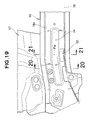
- left and right stiffeners 36 are provided within the left and right rear sections 29 of the left and right front side frames 16, i.e. the left and right bent sections 29, respectively.
- the right stiffener 36 will not be described here because it is of the same construction as the left stiffer 36 except that it is disposed in left-right symmetric relation to the left stiffer 36.
- the left stiffener 36 is a member that reinforces the left bent section 29 in such a manner as to suppress bending of the bent section 29 due to collision force applied from the front of the vehicle body. Also, the left stiffener 36 transmits a lateral collision load to the left outrigger 47 and the left tunnel-side extension 46 when the lateral collision load has acted on the left front side frame 16 from a lateral side of the vehicle body.
- the front end 71 of the left stiffener 36 is located relative to the rear end 69 of the left reinforcing member 35 in such a manner as to allow a load, applied in the front-rear direction of the vehicle body, to be transmitted between the front end 71 and the rear end 69.
- the front end 71 of the left stiffener 36 is located within such a range where a load is transmittable between the front end 71 and the rear end 69 of the left reinforcing member 35, and it faces the rear end 69 of the left reinforcing member 35; for example, the front end 71 of the left stiffener 36 may be located in proximity to or in contact with the rear end 69 of the left reinforcing member 35. In an alternative, the front end 71 of the left stiffener 36 is joined to the left reinforcing member 35.
- the left stiffener 36 is located at an intermediate position, in the front-rear direction, of the left side-sill-side extension 45. Namely, the left stiffener 36 extends from the front end of the left bent section 29, via the left branch section 48, to the left side-sill-side extension 45. Further, as shown in Figs. 12 and 15 , the rear end 72 of the left stiffener 36 is spaced from the bottom plate 45a of the left side-sill-side extension 45 by a predetermined height.
- the left stiffener 36 is a member of an upwardly-opening hat-like sectional shape, and it has: a flat bottom plate 36a; inner and outer plates 36b and 36c projecting upward from the bottom plate 36a; an inner flange 36d bent from the upper end edge of the inner plate 36; and an outer flange 36e bent from the upper end edge of the outer plate 36c.
- the bottom plate 36a, inner plate 36b and outer plate 36c of the stiffener 36 are jointed (e.g. by spot-welding) to the bottom plate 16a, inner wall 16b and outer wall 16c of the bent section 29. Further, the inner plate 36b and outer plate 36c of the stiffener 36 are superposed, from inside, on the inner plate 45b and outer plate 45c and joined to the inner plate 45b and outer plate 45c.
- the inner flange 36d and outer flange 36e are joined to the inner and outer flanges 46d and 46e of the left tunnel-side extension 46 via the inner and outer flanges 45d and 45e of the left side-sill-side extension 45.
- the bottom plate 36a of the left stiffener 36 has a stepped portion 51 and a bead 52 formed thereon.
- the stepped portion 51 is formed by bending the stiffer bottom plate 36a in two stages, i.e. upper and lower stages, in the front-rear direction.
- the stepped portion 51 has an upper mountain fold line 54 and a lower valley fold line 55, and it extends in the vehicle width direction to be located substantially continuously between the rear plate 47c of the left outrigger 47 and the rear wall 49a of the left load receiving section 49.
- the bead 52 is a portion bulging upward from a widthwise middle part of the stiffener bottom plate 36 and extending in a longitudinal direction of the bottom plate 36a, in order to increase the rigidity of the left stiffener 36.
- left and right front end support sections 58 for supporting left and right front end portions 18a of the sub frame 18 by means of left and right fastening members 62 are provided on lower end portions of the left and right front side frames 16, respectively.
- Left and right rear end support sections 59 supporting left and right rear end portions 18b of the sub frame 18 by means of left and right fastening members 62 are provided on lower end portions of the left and right branch sections 48, respectively.
- the right rear end support section 59 will not be described here because it is of the same construction as the left rear end support section 59 except that it is disposed in left-right symmetric relation to the left rear end support section 59.
- the left rear end support section 59 comprises the left stiffener 36, a left sub frame mount bracket 61 and a left collar nut 63.
- the left sub frame mount bracket 61 is spaced downward from the stiffener bottom plate 36a by a predetermined distance and joined to the left bent section 29.
- the left collar nut 63 is a cylindrical member having a female thread formed vertically in its inner surface, and it is located at an intersection point among the first extension line C1, the second extension line C2 and the third extension line C3. Namely, the left rear end support section 59 is located immediately in front of the left load receiving section 49 having a triangular shape as viewed in plan.
- An upper end portion of the left collar nut 63 extends through and is joined to a support hole 53 formed in the bead 52 of the left stiffener 36.
- a lower end portion of the left collar nut 63 is joined to the left sub frame mount bracket 61. Namely, the left collar nut 63 is joined at its upper and lower portions to the left stiffener 36 and the left sub frame mount bracket 61.
- the fastening member 62 ( Fig. 1 ) is screwed into the left collar nut 63.
- the front end 71 of the left stiffener 36 is located relative to the rear end 69 of the reinforcing member 35 in such a manner as to allow a load, applied in the front-rear direction of the vehicle body, to be transmitted to and from the rear end 69 of the reinforcing member 35.
- the collision force from the front of the vehicle body can be readily transmitted straight from the inner wall 16b of the left front side frame 16 to the outer wall 16c of the left front side frame 16 by way of the left reinforcing member 35.
- the collision force having branched from the left branch section 48 outwardly in the vehicle width direction is transmitted to the side sill 23 by way of the left side-sill-side extension 45 and left stiffener 36 as indicated by arrow a3 of Fig. 2 .
- the collision force having branched from the left branch section 48 inwardly in the vehicle width direction is transmitted not only to the left tunnel frame 67 by way of the left tunnel-side extension 46 as indicated by arrow a4 of Fig. 2 but also to the right side sill 23 and right tunnel frame 67 by way of the tunnel cross member 68 as indicated by arrow a2.
- the collision force from the front of the vehicle body is transmitted from one of the front side frames 16 to one of the side sills 23 and the tunnel section 24 located in the vehicle widthwise middle region and then sufficiently dispersed to a rear section of the vehicle body 11.
- left and right side-sill-side extensions 45 are reinforced with the left and right stiffeners 36 (see Fig. 2 ), they have a great strength and rigidity.
- the left and right tunnel-side extensions 46 are not reinforced with stiffeners and have a smaller strength and rigidity than the left and right side-sill-side extensions 45.
- the left and right side sills 23 have a great strength and rigidity. Thus, more of collision force applied from the front of the vehicle body can be received by the high-rigidity left and right side-sill-side extensions 45 and left and right side sills 23.
- the tunnel section 24 does not have to bear much of the collision force from the front of the vehicle body, and thus, it is possible to reduce the size of the left and right tunnel frames 67 or dispense with the left and right tunnel frames 67. As a result, the vehicle body 11 can be reduced in weight.
- the lateral collision force (arrow b1) is transmitted, for example as indicated by arrow b2, from one of the side sills 23 to the rear wall 47c (see Fig. 2 ) of the outrigger 47.
- the collision force having transmitted to the rear wall 47c transmits to one of the tunnel-side extensions 46 as indicated by arrow b3 via the rear wall 49a of the load receiving section 49 ( Fig. 11 ).
- the collision force having transmitted to the tunnel-side extension 46 passes through the tunnel cross member 68 as indicated by arrow b4 and then transmits from the other tunnel-side extension 46 to the other side sill 23 by way of the load receiving section 49 and outrigger 47 as indicated by arrow b5. At that time, the collision force having transmitted to the other load receiving section 49 transmits to the other side sill 23 by way of the side-sill-side extension 45 as indicated by arrow b6.
- the lateral collision force can be sufficiently dispersed in the vehicle width direction by transmitting from one of the side sills 23, the tunnel section 24 provided on the vehicle widthwise middle region and the other side sill 23.
- the left and right reinforcing members 35 are provided within the curved sections 28.
- the left and right reinforcing members 35 each extend substantially straight in the front-rear direction of the vehicle body from a portion, in front of the left or right curved section 28, of the inner wall 16b of the left or right front side frame 16 to a portion, behind the left or right curved section 28, of the outer wall 16c of the left or right front side frame 16.
- the frontal collision force transmits from the front ends of the left and right front side frames 16 to the rear ends of the left and right front side frames 16 by way of the left and right curved sections 28.
- the collision force applied from the front of the vehicle body also transmits from portions, in front of the left and right curved sections 28, of the inner walls 16b to portions, behind the left and right curved sections 28, of the outer walls 16c of the left and right front side frames 16 via the substantially straight left and right reinforcing members 35.
- the collision force from the front of the vehicle body can be efficiently transmitted from the front ends to the rear ends of the left and right front side frames 16 via the substantially straight left and right reinforcing members 35 extending in the front-rear direction through the curved sections.
- the vehicle-traveling power unit 19 (comprising, for example, a transverse-mounted engine and a transmission) can be disposed in a laterally-long orientation in the greater space between the front half portions of the left and right front side frames 16. Further, if left and right front wheels are disposed outward, in the vehicle width direction, of the rear half portions of the left and right front side frames 16 that define the smaller space therebetween, respective steerable ranges of the left and right front wheels can be increased.
- left side-sill-side extension 45 and left tunnel-side extension 46 and the right side-sill-side extension 45 and right tunnel-side extension 46 branch in the vehicle width direction from the respective bent section, extending integrally from the rear ends of the left and right front side frames 16, at equal or substantially equal angles ⁇ 1 and ⁇ 2 with respect to the bent sections.
- collision force applied from the front of the vehicle body can be efficiently dispersed by being transmitted from the rear ends of the left and right front side frames 16 to the curved sections, then from the curved sections to both the left and right side-sill-side extensions 45 and the left and right tunnel-side extensions 46.
- each of the left and right outriggers 47 extends from a portion of the left or right side-sill-side extension 45 opposite from a portion of the left or right side-sill-side extension 45 from which the left or right tunnel-side extension 46 branches. Further, the left and right outriggers 47 extend outward in the vehicle width direction from the outer walls 16c of the bent sections and then are joined to the left and right side sills 23.
- the lateral collision force transmits from one of the left and right side sills 23 to the tunnel section 24 located in the vehicle widthwise middle region of the vehicle body via the outrigger 47, bent section and tunnel-side extension 46 and then transmits from the tunnel section 24 to the vehicle widthwise middle region.
- the left and right side-sill-side extensions 45 extend to the left and right side sills 23 while greatly slanting from the left and right bent sections rearwardly and outwardly in the vehicle width direction, the lateral collision force can be efficiently dispersed from one of the left and right side sills 23 to the vehicle widthwise middle region.
- the left and right reinforcing members 35 include the left and right bulkheads 41 and 42 disposed for partitioning the interior of the left and right curved sections 28 into front and rear interior portions.
- the left and right bulkheads 41 and 42 include the left and right nut members 38 and 39 for supporting the vehicle-traveling power unit 19 disposed between the left and right front side frames 16.
- the rear sections of the left and right front side frames 16 are bent to extend along the underside of the lower dashboard panel 21. Because the thus-bent rear sections of the left and right front side frames 16 are reinforced with the left and right stiffeners 36 provided therein, bending of the bent rear sections due to external force can be suppressed.
- the front ends 71 of the left and right stiffeners 36 are located relative to the rear ends 69 of the left and right reinforcing members 35, disposed in the sections curved inward in the vehicle width direction, in such a manner as to allow a load, applied in the front-rear direction of the vehicle body, to be transmitted to and from the rear ends 69 of the left and right reinforcing members 35.
- collision force from the front of the vehicle body can be transmitted promptly and efficiently to the left and right stiffeners 36 via the left and right reinforcing members 35.
- the left and right front side frames 16 curve inward in the vehicle width direction and bend obliquely rearward and downward, collision force from the front of the vehicle body can be efficiently transmitted from the front ends to the rear ends of the left and right front side frames 16.
- the collision force from the front of the vehicle body can be efficiently dispersed from the front ends of the left and right front side frames 16 toward the rear of the vehicle body.
- each of the left and right reinforcing members 35 is formed in a U sectional shape, and the bead 65 extending in the front-rear direction of the vehicle body is formed on the bottom wall 64, defining the bottom of the U section, of each of the left and right reinforcing members 35.
- the left and right reinforcing members 35 can have an increased strength and rigidity in the front-rear direction of the vehicle body.
- collision force from the front of the vehicle body can be efficiently dispersed from the front ends of the left and right front side frames 16 to the rear ends of the left and right front side frames 16.
- the tunnel section 24 includes the center tunnel 66, the tunnel frames 67 provided on the left and right sides of the center tunnel 66 and the tunnel cross member 68.
- the tunnel cross member 68 connects at least either between the front ends 67a of the left and right tunnel frames 67 or between the rear ends 73 of the left and right tunnel-side extensions 46.
- the left and right fragile portions 32 are provided in the inner walls 16 of the respective curved sections 28 of the left and right front side frames 16.
- the left and right fragile portions 32 are more fragile against a load applied in the front-rear direction of the vehicle body than the other portions in the left and right front side frames 16.
- the left and right fragile portions 32 are located rearward, in the front-rear direction of the vehicle body, of the left and right bulkheads 41 and 42 partitioning the interior of the curved sections 28 into front and rear interior portions.
- the left and right bulkheads 41 and 42 include the left and right nut members 38 and 39 for supporting the vehicle-traveling power unit 19 disposed between the left and right front side frames 16.
- the collision force transmits from the vehicle-traveling power unit 19 to the left and right front side frames 16 via the left and right nut members 38 and 39 and the left and right bulkheads 41 and 42.
- the left and right fragile portions 32 provided in the inner walls 16b of the left and right front side frames 16 can collapse due to the collision force from the front of the vehicle body, as a consequence of which the left and right front side frames 16 are bent outward in the vehicle width direction.
- the provision of such left and right fragile portions can achieve an enhanced collision energy absorbing performance of the front section of the vehicle body.
- the left and right fragile portions 32 are in the form of left and right recessed portions of a simple construction each formed by being merely dented toward the interior of the closed section of the left or right curved section 28.
- the left and right fragile portions 32 are located in portions of a small width, i.e. small sectional area, of the left and right curved sections 28.
- the left and right fragile portions 32 can promote bending of the left and right front side frames 16 due to collision force from the front of the vehicle body.
- each of the left and right reinforcing members 35 formed in a U sectional shape, has the partly-omitted sectional portion 81.
- Such a partly-omitted sectional portion 81 has a lower strength and rigidity than the other portions of the corresponding, i.e. left or right, reinforcing member 35.
- the left and right fragile portions 32 are opposed to the partly-omitted sectional portions 81.
- the front vehicle body structure of the present invention is well suited for application to passenger vehicles, such as sedans and wagons, and particularly small-size vehicles.
Landscapes
- Engineering & Computer Science (AREA)
- Chemical & Material Sciences (AREA)
- Combustion & Propulsion (AREA)
- Transportation (AREA)
- Mechanical Engineering (AREA)
- Body Structure For Vehicles (AREA)
Applications Claiming Priority (3)
| Application Number | Priority Date | Filing Date | Title |
|---|---|---|---|
| JP2011014121 | 2011-01-26 | ||
| JP2011014097 | 2011-01-26 | ||
| PCT/JP2012/051169 WO2012102192A1 (fr) | 2011-01-26 | 2012-01-20 | Structure pour avant de carrosserie de véhicule |
Publications (2)
| Publication Number | Publication Date |
|---|---|
| EP2669150A1 true EP2669150A1 (fr) | 2013-12-04 |
| EP2669150A4 EP2669150A4 (fr) | 2014-09-10 |
Family
ID=46580761
Family Applications (1)
| Application Number | Title | Priority Date | Filing Date |
|---|---|---|---|
| EP20120738727 Withdrawn EP2669150A4 (fr) | 2011-01-26 | 2012-01-20 | Structure pour avant de carrosserie de véhicule |
Country Status (7)
| Country | Link |
|---|---|
| US (1) | US8905466B2 (fr) |
| EP (1) | EP2669150A4 (fr) |
| JP (1) | JP5557930B2 (fr) |
| CN (1) | CN103339020B (fr) |
| BR (1) | BR112013018777B1 (fr) |
| MX (1) | MX2013008239A (fr) |
| WO (1) | WO2012102192A1 (fr) |
Cited By (1)
| Publication number | Priority date | Publication date | Assignee | Title |
|---|---|---|---|---|
| CN105829195A (zh) * | 2014-03-05 | 2016-08-03 | 宝马股份公司 | 以受剪区形式的车辆加固结构 |
Families Citing this family (15)
| Publication number | Priority date | Publication date | Assignee | Title |
|---|---|---|---|---|
| US8882184B2 (en) * | 2011-02-23 | 2014-11-11 | Honda Motor Co., Ltd. | Structure for front portion of automobile body |
| FR2989053B1 (fr) * | 2012-04-05 | 2014-03-21 | Renault Sa | Chassis d'un vehicule automobile comprenant des moyens d'absorption d'un choc frontal |
| BR112015026636A8 (pt) * | 2013-04-26 | 2019-12-24 | Honda Motor Co Ltd | subestrutura de veículo |
| JP6112083B2 (ja) * | 2014-08-21 | 2017-04-12 | トヨタ自動車株式会社 | 車体前部構造 |
| KR101637287B1 (ko) * | 2014-09-02 | 2016-07-07 | 현대자동차 주식회사 | 서브 프레임용 마운팅 유닛 |
| KR101714200B1 (ko) * | 2015-08-28 | 2017-03-08 | 현대자동차주식회사 | 차량 언더바디 구조체 |
| WO2017163307A1 (fr) * | 2016-03-22 | 2017-09-28 | 日産自動車株式会社 | Structure inférieure de carrosserie de véhicule |
| KR101855766B1 (ko) * | 2016-04-28 | 2018-05-09 | 현대자동차 주식회사 | 엔진룸 보강유닛 |
| WO2018016174A1 (fr) * | 2016-07-21 | 2018-01-25 | 本田技研工業株式会社 | Structure de section avant de châssis de véhicule |
| WO2018029941A1 (fr) * | 2016-08-08 | 2018-02-15 | 本田技研工業株式会社 | Structure de carrosserie de véhicule |
| JP6284056B1 (ja) * | 2016-09-13 | 2018-02-28 | マツダ株式会社 | 車両用フレーム構造 |
| JP6819476B2 (ja) * | 2017-06-16 | 2021-01-27 | トヨタ自動車株式会社 | 車両前部構造 |
| JP7156991B2 (ja) * | 2019-03-29 | 2022-10-19 | 本田技研工業株式会社 | サブフレーム構造 |
| KR20210071116A (ko) * | 2019-12-04 | 2021-06-16 | 현대자동차주식회사 | 고전압배터리가 장착되는 차체 |
| JP7550105B2 (ja) * | 2021-04-26 | 2024-09-12 | 本田技研工業株式会社 | 車体前部構造 |
Citations (3)
| Publication number | Priority date | Publication date | Assignee | Title |
|---|---|---|---|---|
| WO2003072421A1 (fr) * | 2002-02-28 | 2003-09-04 | Thyssenkrupp Stahl Ag | Structure porteuse pour vehicules, constituee de profiles d'acier creux |
| US7469957B1 (en) * | 2007-12-07 | 2008-12-30 | Honda Motor Co., Ltd. | Front floor frame |
| EP2105372A1 (fr) * | 2008-03-28 | 2009-09-30 | Mazda Motor Corporation | Structure de cadre pour véhicule automobile, véhicule automobile fourni avec celle-ci et procédé pour fournir une structure de cadre |
Family Cites Families (10)
| Publication number | Priority date | Publication date | Assignee | Title |
|---|---|---|---|---|
| JPH05319308A (ja) * | 1992-05-14 | 1993-12-03 | Mazda Motor Corp | 自動車の前部車体構造及びその組立方法 |
| JP2003063454A (ja) * | 2001-08-24 | 2003-03-05 | Nissan Motor Co Ltd | 自動車の車体前部構造 |
| JP3873980B2 (ja) * | 2004-02-05 | 2007-01-31 | 日産自動車株式会社 | フロントサイドメンバ構造 |
| JP4394032B2 (ja) | 2005-04-15 | 2010-01-06 | 本田技研工業株式会社 | 車体前部構造 |
| JP4233053B2 (ja) * | 2006-04-27 | 2009-03-04 | 本田技研工業株式会社 | 車体前部構造 |
| JP2008201392A (ja) * | 2007-02-23 | 2008-09-04 | Honda Motor Co Ltd | 自動車の前部車体構造 |
| TWI361766B (en) | 2007-07-12 | 2012-04-11 | Honda Motor Co Ltd | Vehicle body frame structure |
| JP5382494B2 (ja) * | 2008-08-08 | 2014-01-08 | スズキ株式会社 | キャニスタの取付構造 |
| WO2011055695A1 (fr) * | 2009-11-05 | 2011-05-12 | 本田技研工業株式会社 | Structure de carrosserie de véhicule |
| GB2490392A (en) * | 2011-04-29 | 2012-10-31 | Gm Global Tech Operations Inc | Diagonally reinforced motor vehicle floor structure |
-
2012
- 2012-01-20 MX MX2013008239A patent/MX2013008239A/es active IP Right Grant
- 2012-01-20 BR BR112013018777-8A patent/BR112013018777B1/pt active IP Right Grant
- 2012-01-20 WO PCT/JP2012/051169 patent/WO2012102192A1/fr active Application Filing
- 2012-01-20 JP JP2012554762A patent/JP5557930B2/ja active Active
- 2012-01-20 CN CN201280006547.1A patent/CN103339020B/zh active Active
- 2012-01-20 EP EP20120738727 patent/EP2669150A4/fr not_active Withdrawn
- 2012-01-20 US US13/981,402 patent/US8905466B2/en active Active
Patent Citations (3)
| Publication number | Priority date | Publication date | Assignee | Title |
|---|---|---|---|---|
| WO2003072421A1 (fr) * | 2002-02-28 | 2003-09-04 | Thyssenkrupp Stahl Ag | Structure porteuse pour vehicules, constituee de profiles d'acier creux |
| US7469957B1 (en) * | 2007-12-07 | 2008-12-30 | Honda Motor Co., Ltd. | Front floor frame |
| EP2105372A1 (fr) * | 2008-03-28 | 2009-09-30 | Mazda Motor Corporation | Structure de cadre pour véhicule automobile, véhicule automobile fourni avec celle-ci et procédé pour fournir une structure de cadre |
Non-Patent Citations (1)
| Title |
|---|
| See also references of WO2012102192A1 * |
Cited By (1)
| Publication number | Priority date | Publication date | Assignee | Title |
|---|---|---|---|---|
| CN105829195A (zh) * | 2014-03-05 | 2016-08-03 | 宝马股份公司 | 以受剪区形式的车辆加固结构 |
Also Published As
| Publication number | Publication date |
|---|---|
| EP2669150A4 (fr) | 2014-09-10 |
| BR112013018777A2 (pt) | 2016-10-25 |
| US8905466B2 (en) | 2014-12-09 |
| WO2012102192A1 (fr) | 2012-08-02 |
| US20130334840A1 (en) | 2013-12-19 |
| CN103339020A (zh) | 2013-10-02 |
| MX2013008239A (es) | 2014-01-31 |
| CN103339020B (zh) | 2015-12-23 |
| BR112013018777B1 (pt) | 2021-02-23 |
| JPWO2012102192A1 (ja) | 2014-06-30 |
| JP5557930B2 (ja) | 2014-07-23 |
Similar Documents
| Publication | Publication Date | Title |
|---|---|---|
| EP2669150A1 (fr) | Structure pour avant de carrosserie de véhicule | |
| EP2617628B1 (fr) | Structure de section avant de carrosserie de véhicule | |
| JP5557929B2 (ja) | 車体前部構造 | |
| EP2689972B1 (fr) | Structure de section d'extrémité de véhicule | |
| US8585134B2 (en) | Vehicle body lower structure | |
| US10583865B2 (en) | Vehicle rear structure | |
| JP5953887B2 (ja) | 車両の車体前部構造 | |
| US20170217501A1 (en) | Vehicle body structure | |
| US7407192B2 (en) | Vehicle end structure | |
| WO2013018417A1 (fr) | Structure arrière de carrosserie de véhicule | |
| US7008007B2 (en) | Vehicle body end structure | |
| JP5698340B2 (ja) | 車体後部構造 | |
| US8651564B2 (en) | Polygonal cross-sectional frame, and rear vehicle body structure | |
| JP6511078B2 (ja) | 電気自動車のフロア構造 | |
| JP6557290B2 (ja) | 車体前部構造 | |
| EP3536530B1 (fr) | Structure de carrosserie de véhicule | |
| US10787202B2 (en) | Vehicle chassis front section structure | |
| KR20200139057A (ko) | 차체구조물 및 이를 포함하는 차량 | |
| JP6065993B2 (ja) | 車両の車体前部構造 | |
| JP2008132830A (ja) | 車両の前部構造 | |
| CN209888934U (zh) | 后围总成和具有其的车辆 | |
| JP2020040594A (ja) | 車両前部構造 | |
| JP2017132466A (ja) | 車両の車体前部構造 |
Legal Events
| Date | Code | Title | Description |
|---|---|---|---|
| PUAI | Public reference made under article 153(3) epc to a published international application that has entered the european phase |
Free format text: ORIGINAL CODE: 0009012 |
|
| 17P | Request for examination filed |
Effective date: 20130718 |
|
| AK | Designated contracting states |
Kind code of ref document: A1 Designated state(s): AL AT BE BG CH CY CZ DE DK EE ES FI FR GB GR HR HU IE IS IT LI LT LU LV MC MK MT NL NO PL PT RO RS SE SI SK SM TR |
|
| DAX | Request for extension of the european patent (deleted) | ||
| A4 | Supplementary search report drawn up and despatched |
Effective date: 20140811 |
|
| RIC1 | Information provided on ipc code assigned before grant |
Ipc: B62D 25/08 20060101ALI20140805BHEP Ipc: B62D 25/20 20060101AFI20140805BHEP Ipc: B62D 21/11 20060101ALI20140805BHEP |
|
| GRAP | Despatch of communication of intention to grant a patent |
Free format text: ORIGINAL CODE: EPIDOSNIGR1 |
|
| RIC1 | Information provided on ipc code assigned before grant |
Ipc: B62D 21/11 20060101ALI20150416BHEP Ipc: B62D 25/08 20060101ALI20150416BHEP Ipc: B62D 25/20 20060101AFI20150416BHEP |
|
| INTG | Intention to grant announced |
Effective date: 20150511 |
|
| STAA | Information on the status of an ep patent application or granted ep patent |
Free format text: STATUS: THE APPLICATION IS DEEMED TO BE WITHDRAWN |
|
| 18D | Application deemed to be withdrawn |
Effective date: 20150922 |