EP2668005B1 - Werkzeugspannvorrichtung - Google Patents
Werkzeugspannvorrichtung Download PDFInfo
- Publication number
- EP2668005B1 EP2668005B1 EP11802759.8A EP11802759A EP2668005B1 EP 2668005 B1 EP2668005 B1 EP 2668005B1 EP 11802759 A EP11802759 A EP 11802759A EP 2668005 B1 EP2668005 B1 EP 2668005B1
- Authority
- EP
- European Patent Office
- Prior art keywords
- tool
- clamping
- axial direction
- unit
- along
- Prior art date
- Legal status (The legal status is an assumption and is not a legal conclusion. Google has not performed a legal analysis and makes no representation as to the accuracy of the status listed.)
- Active
Links
- 230000033001 locomotion Effects 0.000 claims description 38
- 238000003754 machining Methods 0.000 claims description 15
- 238000006243 chemical reaction Methods 0.000 claims description 6
- 239000011295 pitch Substances 0.000 claims description 2
- 230000010355 oscillation Effects 0.000 claims 1
- 238000010586 diagram Methods 0.000 description 6
- 230000005540 biological transmission Effects 0.000 description 4
- 230000006835 compression Effects 0.000 description 4
- 238000007906 compression Methods 0.000 description 4
- 230000001419 dependent effect Effects 0.000 description 3
- 230000000694 effects Effects 0.000 description 2
- 239000000463 material Substances 0.000 description 2
- 150000001875 compounds Chemical class 0.000 description 1
- 238000000034 method Methods 0.000 description 1
- 239000011343 solid material Substances 0.000 description 1
Images

Classifications
-
- B—PERFORMING OPERATIONS; TRANSPORTING
- B24—GRINDING; POLISHING
- B24B—MACHINES, DEVICES, OR PROCESSES FOR GRINDING OR POLISHING; DRESSING OR CONDITIONING OF ABRADING SURFACES; FEEDING OF GRINDING, POLISHING, OR LAPPING AGENTS
- B24B23/00—Portable grinding machines, e.g. hand-guided; Accessories therefor
- B24B23/04—Portable grinding machines, e.g. hand-guided; Accessories therefor with oscillating grinding tools; Accessories therefor
-
- A—HUMAN NECESSITIES
- A61—MEDICAL OR VETERINARY SCIENCE; HYGIENE
- A61B—DIAGNOSIS; SURGERY; IDENTIFICATION
- A61B17/00—Surgical instruments, devices or methods, e.g. tourniquets
- A61B17/14—Surgical saws ; Accessories therefor
- A61B17/142—Surgical saws ; Accessories therefor with reciprocating saw blades, e.g. with cutting edges at the distal end of the saw blades
-
- B—PERFORMING OPERATIONS; TRANSPORTING
- B24—GRINDING; POLISHING
- B24B—MACHINES, DEVICES, OR PROCESSES FOR GRINDING OR POLISHING; DRESSING OR CONDITIONING OF ABRADING SURFACES; FEEDING OF GRINDING, POLISHING, OR LAPPING AGENTS
- B24B23/00—Portable grinding machines, e.g. hand-guided; Accessories therefor
- B24B23/02—Portable grinding machines, e.g. hand-guided; Accessories therefor with rotating grinding tools; Accessories therefor
- B24B23/022—Spindle-locking devices, e.g. for mounting or removing the tool
-
- B—PERFORMING OPERATIONS; TRANSPORTING
- B24—GRINDING; POLISHING
- B24B—MACHINES, DEVICES, OR PROCESSES FOR GRINDING OR POLISHING; DRESSING OR CONDITIONING OF ABRADING SURFACES; FEEDING OF GRINDING, POLISHING, OR LAPPING AGENTS
- B24B23/00—Portable grinding machines, e.g. hand-guided; Accessories therefor
- B24B23/04—Portable grinding machines, e.g. hand-guided; Accessories therefor with oscillating grinding tools; Accessories therefor
- B24B23/046—Clamping or tensioning means for abrasive sheets
-
- B—PERFORMING OPERATIONS; TRANSPORTING
- B24—GRINDING; POLISHING
- B24B—MACHINES, DEVICES, OR PROCESSES FOR GRINDING OR POLISHING; DRESSING OR CONDITIONING OF ABRADING SURFACES; FEEDING OF GRINDING, POLISHING, OR LAPPING AGENTS
- B24B45/00—Means for securing grinding wheels on rotary arbors
-
- B—PERFORMING OPERATIONS; TRANSPORTING
- B24—GRINDING; POLISHING
- B24B—MACHINES, DEVICES, OR PROCESSES FOR GRINDING OR POLISHING; DRESSING OR CONDITIONING OF ABRADING SURFACES; FEEDING OF GRINDING, POLISHING, OR LAPPING AGENTS
- B24B45/00—Means for securing grinding wheels on rotary arbors
- B24B45/003—Accessories therefor
-
- B—PERFORMING OPERATIONS; TRANSPORTING
- B24—GRINDING; POLISHING
- B24B—MACHINES, DEVICES, OR PROCESSES FOR GRINDING OR POLISHING; DRESSING OR CONDITIONING OF ABRADING SURFACES; FEEDING OF GRINDING, POLISHING, OR LAPPING AGENTS
- B24B45/00—Means for securing grinding wheels on rotary arbors
- B24B45/006—Quick mount and release means for disc-like wheels, e.g. on power tools
-
- B—PERFORMING OPERATIONS; TRANSPORTING
- B27—WORKING OR PRESERVING WOOD OR SIMILAR MATERIAL; NAILING OR STAPLING MACHINES IN GENERAL
- B27B—SAWS FOR WOOD OR SIMILAR MATERIAL; COMPONENTS OR ACCESSORIES THEREFOR
- B27B19/00—Other reciprocating saws with power drive; Fret-saws
- B27B19/006—Other reciprocating saws with power drive; Fret-saws with oscillating saw blades; Hand saws with oscillating saw blades
-
- B—PERFORMING OPERATIONS; TRANSPORTING
- B27—WORKING OR PRESERVING WOOD OR SIMILAR MATERIAL; NAILING OR STAPLING MACHINES IN GENERAL
- B27B—SAWS FOR WOOD OR SIMILAR MATERIAL; COMPONENTS OR ACCESSORIES THEREFOR
- B27B5/00—Sawing machines working with circular or cylindrical saw blades; Components or equipment therefor
- B27B5/29—Details; Component parts; Accessories
- B27B5/30—Details; Component parts; Accessories for mounting or securing saw blades or saw spindles
- B27B5/32—Devices for securing circular saw blades to the saw spindle
-
- Y—GENERAL TAGGING OF NEW TECHNOLOGICAL DEVELOPMENTS; GENERAL TAGGING OF CROSS-SECTIONAL TECHNOLOGIES SPANNING OVER SEVERAL SECTIONS OF THE IPC; TECHNICAL SUBJECTS COVERED BY FORMER USPC CROSS-REFERENCE ART COLLECTIONS [XRACs] AND DIGESTS
- Y10—TECHNICAL SUBJECTS COVERED BY FORMER USPC
- Y10T—TECHNICAL SUBJECTS COVERED BY FORMER US CLASSIFICATION
- Y10T279/00—Chucks or sockets
- Y10T279/33—Member applies axial force component
Definitions
- Tool clamping devices in particular oscillating tool clamping devices, which have a clamping unit are already known.
- the clamping unit in this case has a clamping element for clamping a machining tool in an axial direction and an operating unit for actuating the clamping element, as for example in the documents DE 20 2008 001 759 U1 and EP 1 180 416 A2 ,
- the invention is based on a tool clamping device, in particular of an oscillating tool clamping device, with at least one clamping unit which has at least one clamping element for clamping a machining tool in an axial direction and at least one operating unit for actuating the clamping element.
- the tool clamping device comprises at least one translation unit which is provided to change a transmission ratio as a function of at least one movement component of an operating element of the operating unit.
- the term "provided" is intended to define specifically equipped and / or specially designed.
- a “clamping unit” is to be understood here in particular as a unit which secures a machining tool by means of a positive connection and / or by means of a frictional connection along the axial direction, in particular on a tool holder of a portable machine tool.
- the clamping element of the clamping unit is formed pin-shaped.
- a “pin-shaped clamping element” is to be understood here in particular as a tensioning element which, in an assembled state, has a longitudinal extent along the axial direction that is greater than a transverse extent of the tensioning element along a direction perpendicular to the axial direction.
- the longitudinal extension is more than twice as large as the transverse extent of the tensioning element, preferably more than four times as large, and more preferably more than six times as large.
- the pin-shaped clamping element is at least partially formed as a hollow body.
- the clamping element has at least two partial regions designed as legs, which are arranged at least partially spaced apart along a direction extending at least substantially perpendicular to the axial direction.
- the clamping element is arranged captively in a hollow shaft of the portable power tool.
- the clamping unit has a clamping head arranged on the clamping element. In this case, the clamping head preferably comprises two partial areas which are movable relative to one another.
- the portions of the chuck are preferably formed integrally with one of the legs of the clamping element.
- a "chucking head” is to be understood here in particular as an element which has at least one clamping surface which bears against the clamping of the machining tool in the axial direction at least on a partial surface of the machining tool and acts on the machining tool with a clamping force along the axial direction.
- the term "axial direction” should in particular define a direction which preferably extends at least substantially parallel to a pivot axis and / or rotation axis of a drive shaft and / or spindle of a portable power tool provided for driving the machining tool.
- substantially parallel is to be understood here as meaning, in particular, an alignment of a direction relative to a reference direction, in particular in a plane, wherein the direction relative to the reference direction is a deviation, in particular less than 8 °, advantageously less than 5 ° and particularly advantageously less than 2 °.
- control unit is to be understood here as meaning, in particular, a unit which has at least one operating element which is directly accessible to an operator is operable, and which is intended to influence and / or change by means of an actuation and / or by input of parameters, a process and / or a state of a unit coupled to the operating unit.
- unit of translation is intended to define a unit intended to translate at least one value of a physical quantity, such as a speed, torque, force, etc., into another value of the same physical quantity, both values in a fixed ratio, in particular in a structurally determined relationship to each other.
- the translation unit is formed by a mechanical translation unit.
- the translation unit is designed in another way, which appears appropriate to a person skilled in the art.
- a “movement component” is to be understood here in particular as a component of a movement variable which defines a movement mathematically, such as a path, a speed, an angle, etc.
- the movement component is formed by an angle, in particular an opening angle, which the Operating element of the operating unit sweeps in a movement starting from a starting position.
- starting position should in particular define a position of the operating element in which a force effect of the operating element on the translation unit and / or the clamping unit for actuating the clamping unit is canceled and / or prevented.
- the translation unit changes a transmission ratio between a traveled distance of the operating element, in particular about an axis of rotation extending at least substantially parallel to the axial direction, and a distance traveled by the clamping element along the axial direction as a function of an opening angle swept by the operating element.
- the term "gear ratio" is intended here to define in particular a ratio of physical values which can be changed by means of the translation unit relative to one another, wherein both physical values deviate from zero, in particular the ratio itself likewise deviates from a value of zero and / or infinity.
- the translation unit comprise at least one control cam which, viewed along a course of the control cam in at least two different points of the control cam, has mutually different slopes in the axial direction.
- the different gradients of the cam in each of the two different points along a curve of the cam on a non-zero value are to be understood here in particular as a geometric shape which is intended to convert a movement form into another movement form and / or which is intended to control a component as a result of a movement, in particular a movement of the control cam about an axis which, as a result of the movement, carries out a movement predetermined by the geometric shape.
- the control cam is provided to convert a rotational movement in a translational movement.
- the term "slope" should in particular define a measure of a steepness of the control curve, in particular considered in a plane and / or a projection plane.
- the slope is formed by a mathematically defined slope, which can be determined by means of a difference quotient and / or by means of a differential equation in any point of the control curve.
- the control cam is arranged on one of the operating unit facing side of the clamping element on the clamping element.
- the control cam is formed integrally with the clamping element.
- an actuating force to be applied by an operator for actuating the clamping element can be influenced in a particularly advantageous manner by means of the operating unit; in particular, advantageously, a profile of the actuating force can be changed as a function of an opening angle of the operating element.
- the translation unit has at least one scanning element, which is provided to the clamping element in dependence of the course the cam to move along the axial direction.
- a "sensing element” is to be understood here in particular an element which scans the course of the control cam, in particular scans mechanically, and as a result of the course of the control cam controls a component which executes a dependent of the course of the control cam movement.
- the sensing element is at least in an operating state on the control cam. It can be advantageously achieved by the course of the control cam dependent movement of the clamping element.
- the sensing element is designed as a bolt.
- a "bolt” is to be understood here as meaning, in particular, an element which has a longitudinal extent which is greater than a transverse extent running perpendicular to the longitudinal extent.
- the bolt is cylindrical.
- the bolt is rotationally symmetrical about at least one axis.
- the bolt is formed of a solid material.
- the sensing element has another, a skilled person appear useful design. It can structurally simple a scanning element can be achieved.
- the bolt has a longitudinal extent which extends in an assembled state along a direction extending at least substantially perpendicular to the axial direction.
- the bolt has a longitudinal extent, which extends in an assembled state for sensing a course of the control cam along another direction that appears appropriate to a person skilled in the art. It can structurally simple contact surface and / or a contact surface between the bolt and the cam can be achieved.
- the tool clamping device comprises at least one decoupling unit which is provided for decoupling the operating unit in at least one operating mode from a movement of the clamping element.
- a "decoupling unit” is to be understood here in particular as a unit which has at least one mechanism and / or at least one component which effects a decoupling, in particular a decoupling of movements, between at least two elements.
- the decoupling unit is preferred intended to decouple the operating unit in at least one operating mode from an oscillating movement of the clamping element about an at least substantially parallel to the axial direction extending pivot axis of the clamping element.
- a protection of components in at least one operating mode can be achieved.
- the decoupling unit has at least one stop element, which is provided to limit a movement of the clamping element along the axial direction in the direction of the operating unit.
- the stop element is provided due to the limitation of the movement of the clamping element along the axial direction to ensure, at least in one operating state, a distance between the sensing element and the control cam along a direction perpendicular to the axial direction.
- a transmission of a movement of the clamping element via the control cam and the scanning element in at least one operating state to the operating element of the operating unit can be prevented.
- the operating element of the operating unit is designed as an operating lever, which is mounted pivotably about a pivot axis extending parallel to the axial direction.
- the operating lever is pivotally and / or rotatably mounted in a machine tool housing of the portable power tool.
- the operating lever is designed as a one-sided lever, are initiated in the actuating forces on one side of the operating lever.
- the operating lever is designed in another, a person skilled in the sense appearing manner.
- an actuating force of an operator for actuating the tensioning element can be applied by means of the operating lever.
- the operating unit comprises at least one Abtastworkelement for receiving a sensing element of the operating unit, which is at least rotatably connected to the operating lever.
- rotatably connected should be understood in particular a compound that transmits a torque and / or rotational movement unchanged.
- the Abtastworkelement by means of a screw rotatably with the operating lever connected.
- the Abtastworkelement by means of another, a person skilled in the sense appearing connection, such as cohesively and / or positively connected to the operating lever.
- the Abtastworkelement has at least one recess in which the scanning element is arranged in an assembled state. It can be advantageously achieved a storage of the sensing element.
- structurally simple the scanning element as a result of the movement of the operating lever to scan the course of the control cam and thus move the clamping element along the axial direction.
- the invention is based on a portable power tool, in particular a portable power tool with an oscillating drivable spindle, with at least one tool clamping device according to the invention.
- a "portable machine tool” is to be understood here in particular as meaning a machine tool, in particular a hand tool machine, which can be transported without transport machine by an operator.
- the portable power tool has a mass which is less than 40 kg, preferably less than 10 kg and particularly preferably less than 5 kg. It can be advantageously achieved a high ease of use for an operator of the machine tool.
- the tool clamping device according to the invention should not be limited to the application and embodiment described above.
- the tool clamping device according to the invention can have a number deviating from a number of individual elements, components and units specified here in order to fulfill a mode of operation described herein.
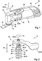
- FIG. 1 1 shows an electrically operated portable power tool 42 having a tool clamping device 10.
- the portable power tool 42 includes a power tool housing 44 that encloses an electric motor unit 46, a gear unit 48 and an output unit 50 of the portable power tool 42.
- the machine tool housing 44 in this case comprises two housing halves 52, 54 which are releasably connected to each other along a plane passing through an axial direction 18 level.
- the machine tool housing 44 has two or more cup-shaped housing parts which are releasably connectable to each other.
- the axial direction 18 runs along and / or parallel to a rotation axis 56 of a spindle 58 designed as a Hollow shaft 60 of the output unit 50 (FIG. FIG. 2 ).
- the hollow shaft 60 is provided to oscillate in a mounted state, a machining tool 16 to drive.
- An oscillating drive of the machining tool 16 in this case takes place in a manner already known to a person skilled in the art, such as by means of an eccentrically arranged on a drive shaft of the electric motor unit 46 pin (not shown here) of the gear unit 48, by means of a rocker and an oscillating sleeve (here not shown in more detail) of the gear unit 48 drives the hollow shaft 60 in an operation of the portable power tool 42.
- the spindle 58 designed as a hollow shaft 60 is driven in an oscillating manner.
- the machining tool 16 can be fastened to a tool holder 62 of the output unit 50 for machining workpieces.
- the tool holder 62 is non-rotatably connected by means of a positive and / or non-positive connection with the hollow shaft 60.
- the tool holder 62 is formed integrally with the hollow shaft 60. It can be a pivoting movement of the hollow shaft 60 are transmitted to the tool holder 62.
- FIG. 2 shows a detailed view of the tool clamping device 10.
- the tool clamping device 10 comprises a clamping unit 12 which has a clamping element 14 for clamping the machining tool 16 in the axial direction 18 and an operating unit 20 for actuating the clamping element 14.
- the clamping element 14 is pin-shaped.
- the clamping element 14 is movably arranged in the hollow shaft 60. In this case, the clamping element 14 extends along the axial direction 18 through the hollow shaft 60 therethrough.
- the clamping element 14 is arranged in a mounted state in the hollow shaft 60.
- the clamping element 14 has two legs 64, 66, which extend in an assembled state of the clamping element 14 at least substantially along the axial direction 18.
- the legs 64, 66 are formed integrally with the clamping element 14.
- the legs 64, 66 have a low material thickness, viewed along a direction perpendicular to the axial direction 18, in order to enable a deflection of the legs 64, 66.
- the legs 64, 66 as a result of material properties and / or a geometric shape of the legs 64, 66 are arranged relative to each other movable on the clamping element 14.
- the legs 64, 66 are in this case resiliently arranged on the clamping element 14.
- the legs 64, 66 along arranged perpendicular to the axial direction 18 extending direction relative to each other. The legs 64, 66 can move relative to each other due to the resilient arrangement on the clamping element 14 and the relative distance to each other along the direction perpendicular to the axial direction 18 extending direction.
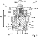
- the clamping unit 12 has a spring element 68, which is provided to act on the clamping element 14 along the axial direction 18 with a spring force ( FIG. 5 ).
- the spring element 68 is formed here as a compression spring 70.
- the spring element 68 is formed by another, a skilled person appearing appropriate spring element, such as a tension spring, a plate spring, etc.
- the clamping unit 12 more than a spring element 68 for acting on the Has clamping element 14 with a spring force.
- the clamping element 14 extends in an assembled state along the axial direction 18 through the compression spring 70 therethrough.
- the compression spring 70 is arranged along a circumferential direction 72 at least about a portion of the clamping element 14.
- the circumferential direction 72 extends in a plane which is at least substantially perpendicular to the axial direction 18.
- the compression spring 70 is supported in an assembled state with one end 74 on a contact surface 76 of the clamping element 14.
- the contact surface 76 is annular in this case.
- the tool clamping device 10 further comprises a translation unit 22 which is provided to change a transmission ratio as a function of at least one movement component of a control element 24 of the operating unit 20.
- the operating element 24 of the operating unit 20 is designed as an operating lever 36, which is mounted pivotably about a pivot axis 38 extending parallel to the axial direction 18.
- the pivot axis 38 in this case runs coaxially to the axis of rotation 56 of the hollow shaft 60.
- the translation unit 22 comprises a control cam 26 which, viewed along a curve of the control curve 26 in at least two different points of the control curve 26, has mutually different slopes in the axial direction 18 (FIG. FIG. 3 ).
- the control cam 26 is arranged on one of the operating unit 20 facing side of the clamping element 14.
- control cam 26 is integral with the clamping element fourteenth educated.
- the translation unit 22 also has a further control cam (not shown in detail here), which is arranged offset along the circumferential direction 72 to the control cam 26 on the clamping element 14.
- the further control cam has an analogous to the control curve 26 course.
- the further control cam viewed along a curve of the further control cam in at least two different points of the further control cam, has mutually different pitches in the axial direction 18.
- the translation unit 22 has a sensing element 28, which is provided to move the clamping element 14 in dependence on the course of the control cam 26 along the axial direction 18.
- the sensing element 28 is formed as a bolt 30.
- the bolt 30 has a longitudinal extent, which extends in an assembled state along a direction extending at least substantially perpendicular to the axial direction 18.
- the bolt 30 is intended to be brought in at least one operating mode in each case with two opposite ends of the bolt 30 with the control cam 26 and the other control cam in contact.
- the operating unit 20 comprises a Abtastworkelement 40 for receiving the sensing element 28 of the control unit 20, which is rotatably connected to the operating lever 36.
- the Abtastworkelement 40 extends in an assembled state along the axial direction 18.
- the Abtastworkelement 40 has a recess 78 which extends along an at least substantially perpendicular to the axial direction 18 extending through the Abtastanalysiselement 40.
- the recess 78 is formed by a through hole in which the sensing element 28 is arranged in an assembled state.
- a diameter of the recess 78 corresponds at least substantially to a dimension of the sensing element 28 along the axial direction 18.
- the sensing element 28 is held in the recess 78 by means of a press fit.
- the scanning element 28 it is also conceivable for the scanning element 28 to be held in the recess 78 in another manner which appears appropriate to a person skilled in the art.
- the sensing element 28 is formed integrally with the Abtastanalysiselement 40 and extending along an at least substantially perpendicular to the axial direction 18 extending direction at least two locations of the Abtastanalysiselement 40 away.
- the Abtastworkelement 40 is also intended to a bearing function of the operating lever 36 in the machine tool housing 44 ( FIG. 4 ).
- a ball bearing 80 designed as a bearing element 82 is arranged on the Abtastamelement 40.
- the ball bearing 80 encloses the Abtastageelement 40 in a portion of the Abtastanalysiselements 40 along the circumferential direction 72nd
- the tool clamping device 10 further has a decoupling unit 32, which is provided to decouple the operating unit 20 in at least one operating mode from a movement of the clamping element 14.
- the decoupling unit 32 is provided to decouple the operating unit 20 in at least one operating mode from an oscillating movement of the clamping element 14 about the axis of rotation 56.
- the decoupling unit 32 has a stop element 34, which is provided to limit a movement of the clamping element 14 along the axial direction 18 in the direction of the operating unit 20.
- the stop element 34 is in this case in an operating mode along the axial direction 18 at a projection of the hollow shaft 60 at.
- the arranged on the clamping element 14 control cam 26 and the other control cam are thus arranged in an operating mode along the axial direction 18 spaced from the sensing element 28.
- the operating lever 36 To mount the machining tool 16 on the tool holder 62, the operating lever 36, starting from a voltage applied to the machine tool housing 44 position of the operating lever 36, moved by the operator in a direction away from the machine tool housing 44 direction and thus rotated about the pivot axis 38.
- the sensing element 28 is first moved in the direction of the control cam 26 and the other cam until ends of the trained as a bolt 30 sensing element 28 come into contact with the control cam 26 and the other control cam.
- the trained as a bolt 30 sensing element 28 slides along the control cam 26 and the other control cam.
- the clamping element 14 is moved along the axial direction 18 in the direction of the tool holder 62.
- the clamping unit 12 is thereby transferred into a tool change mode.
- the movement of the clamping element 14 along the axial direction 18 in the direction of the tool holder 62 is dependent on a course of the control cam 26 and the further cam and an opening angle of the operating lever 36.
- the opening angle is swept by the operating lever 36 at a movement of the operating lever 36 about the pivot axis 38, starting from the voltage applied to the machine tool housing 44 position of the operating lever 36.
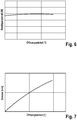
- FIG. 6 shows a relationship between the swept by the operating lever 36 opening angle and an applied by an operator operating force to move the clamping member 14 along the axial direction 18 in a diagram.
- the diagram shows a disproportionate course of the actuating force to the opening angle due to the course and / or a geometry of the control cam 26 and the other cam.
- an actuating force to be applied by the operator for moving the tensioning element 14 along the axial direction 18 as a result of the course and / or the geometry of the control cam 26 and the further control curve is disproportionate to the opening angle of the operating lever 36.
- FIG. 7 shows a relationship between a distance traveled by the clamping element 14 along the axial direction 18 and the swept by the operating lever 36 opening angle in another diagram.
- a course of the route is due to the course of the control cam 26 and the other control cam disproportionate to the opening angle.
- the further diagram shows a disproportionate course of the distance to the opening angle due to the course and / or the geometry of the control cam 26 and the other cam.
- a distance of the tensioning element 14 along the axial direction 18 due to the course and / or the geometry of the control cam 26 and the further control cam is also disproportionate to the opening angle of the operating lever 36 when the tensioning element 14 is actuated by the operating unit 20.
Landscapes
- Engineering & Computer Science (AREA)
- Mechanical Engineering (AREA)
- Jigs For Machine Tools (AREA)
- Cutting Tools, Boring Holders, And Turrets (AREA)
- Clamps And Clips (AREA)
- Constituent Portions Of Griding Lathes, Driving, Sensing And Control (AREA)
Description
- Es sind bereits Werkzeugspannvorrichtungen, insbesondere Oszillationswerkzeugspannvorrichtungen, bekannt, die eine Spanneinheit aufweisen. Die Spanneinheit weist hierbei ein Spannelement zu einem Festspannen eines Bearbeitungswerkzeugs in einer Axialrichtung und eine Bedieneinheit zur Betätigung des Spannelements auf, wie zum Beispiel in den Druckschriften
DE 20 2008 001 759 U1 undEP 1 180 416 A2 . - Die Erfindung geht aus von einer Werkzeugspannvorrichtung, insbesondere von einer Oszillationswerkzeugspannvorrichtung, mit zumindest einer Spanneinheit, die zumindest ein Spannelement zu einem Festspannen eines Bearbeitungswerkzeugs in einer Axialrichtung sowie zumindest eine Bedieneinheit zur Betätigung des Spannelements aufweist.
Es wird vorgeschlagen, dass die Werkzeugspannvorrichtung zumindest eine Übersetzungseinheit umfasst, die dazu vorgesehen ist, in Abhängigkeit zumindest einer Bewegungskomponente eines Bedienelements der Bedieneinheit ein Übersetzungsverhältnis zu verändern. In diesem Zusammenhang soll der Begriff "vorgesehen" speziell ausgestattet und/oder speziell ausgelegt definieren. Unter einer "Spanneinheit" soll hier insbesondere eine Einheit verstanden werden, die ein Bearbeitungswerkzeug mittels eines Formschlusses und/oder mittels eines Kraftschlusses entlang der Axialrichtung sichert, insbesondere an einer Werkzeugaufnahme einer tragbaren Werkzeugmaschine. Bevorzugt wirkt in einem Spannmodus der Spanneinheit eine Spannkraft entlang der Axialrichtung auf das Bearbeitungswerkzeug. Bevorzugt ist das Spannelement der Spanneinheit stiftförmig ausgebildet. Unter einem "stiftförmigen Spannelement" soll hier insbesondere ein Spannelement verstanden werden, das in einem montierten Zustand eine Längserstreckung entlang der Axialrichtung aufweist, die größer ist als eine Quererstreckung des Spannelements entlang einer senkrecht zur Axialrichtung verlaufenden Richtung. Insbesondere ist die Längserstreckung mehr als doppelt so groß als die Querstreckung des Spannelements, bevorzugt mehr als vier Mal so groß und besonders bevorzugt mehr als sechs Mal so groß. Bevorzugt ist das stiftförmige Spannelement zumindest teilweise als Hohlkörper ausgebildet. Besonders bevorzugt weist das Spannelement zumindest zwei als Schenkel ausgebildete Teilbereiche auf, die zumindest teilweise entlang einer zumindest im Wesentlichen senkrecht zur Axialrichtung verlaufenden Richtung relativ zueinander beabstandet angeordnet sind. Vorzugsweise ist das Spannelement verliersicher in einer Hohlwelle der tragbaren Werkzeugmaschine angeordnet. Besonders bevorzugt weist die Spanneinheit einen am Spannelement angeordneten Spannkopf auf. Hierbei umfasst der Spannkopf vorzugsweise zwei relativ zueinander bewegliche Teilbereiche. Die Teilbereiche des Spannkopfs sind bevorzugt jeweils einstückig mit einem der Schenkel des Spannelements ausgebildet. Unter einem "Spannkopf" soll hier insbesondere ein Element verstanden werden, das zumindest eine Spannfläche aufweist, die zum Festspannen des Bearbeitungswerkzeugs in Axialrichtung zumindest an einer Teilfläche des Bearbeitungswerkzeugs anliegt und das Bearbeitungswerkzeug mit einer Spannkraft entlang der Axialrichtung beaufschlagt. Der Begriff "Axialrichtung" soll hier insbesondere eine Richtung definieren, die bevorzugt zumindest im Wesentlichen parallel zu einer Schwenkachse und/oder Rotationsachse einer zum Antrieb des Bearbeitungswerkzeugs vorgesehenen Antriebswelle und/oder Spindel einer tragbaren Werkzeugmaschine verläuft. Unter "im Wesentlichen parallel" soll hier insbesondere eine Ausrichtung einer Richtung relativ zu einer Bezugsrichtung, insbesondere in einer Ebene, verstanden werden, wobei die Richtung gegenüber der Bezugsrichtung eine Abweichung insbesondere kleiner als 8°, vorteilhaft kleiner als 5° und besonders vorteilhaft kleiner als 2° aufweist. - Unter einer "Bedieneinheit" soll hier insbesondere eine Einheit verstanden werden, die zumindest ein Bedienelement aufweist, das direkt von einem Bediener betätigbar ist, und die dazu vorgesehen ist, durch eine Betätigung und/oder durch eine Eingabe von Parametern einen Prozess und/oder einen Zustand einer mit der Bedieneinheit gekoppelten Einheit zu beeinflussen und/oder zu ändern. Der Begriff "Übersetzungseinheit" soll hier insbesondere eine Einheit definieren, die dazu vorgesehen ist, zumindest einen Wert einer physikalischen Größe, wie beispielsweise eine Drehzahl, ein Drehmoment, eine Kraft usw., in einen anderen Wert derselben physikalischen Größe zu übersetzen, wobei beide Werte in einem festgelegten Verhältnis, insbesondere in einem konstruktiv festgelegten Verhältnis, zueinander stehen. Bevorzugt wird die Übersetzungseinheit von einer mechanischen Übersetzungseinheit gebildet. Es ist jedoch auch denkbar, dass die Übersetzungseinheit auf eine andere, einem Fachmann als sinnvoll erscheinenden Art und Weise ausgestaltet ist.
- Unter einer "Bewegungskomponente" soll hier insbesondere eine Komponente einer Bewegungsgröße verstanden werden, die eine Bewegung mathematisch definiert, wie beispielsweise ein Weg, eine Geschwindigkeit, ein Winkel usw. Bevorzugt wird die Bewegungskomponente von einem Winkel, insbesondere von einem Öffnungswinkel, gebildet, den das Bedienelement der Bedieneinheit bei einer Bewegung ausgehend von einer Ausgangsstellung überstreicht. Der Begriff "Ausgangsstellung" soll hier insbesondere eine Position des Bedienelements definieren, in der eine Krafteinwirkung des Bedienelements auf die Übersetzungseinheit und/oder die Spanneinheit zur Betätigung der Spanneinheit aufgehoben und/oder unterbunden ist. Bevorzugt wird durch die Übersetzungseinheit in Abhängigkeit eines von dem Bedienelement überstrichenen Öffnungswinkels ein Übersetzungsverhältnis zwischen einer zurückgelegten Strecke des Bedienelements, insbesondere um eine zumindest im Wesentlichen parallel zur Axialrichtung verlaufenden Rotationsachse, und einer von dem Spannelement zurückgelegten Strecke entlang der Axialrichtung geändert. Der Begriff "Übersetzungsverhältnis" soll hier insbesondere ein Verhältnis von mittels der Übersetzungseinheit änderbaren physikalischen Werten relativ zueinander definieren, wobei beide physikalischen Werte von Null abweichend sind, insbesondere ist das Verhältnis selbst ebenfalls von einem Wert von Null und/oder Unendlich abweichend. Mittels der erfindungsgemäßen Ausgestaltung der Werkzeugspannvorrichtung kann vorteilhaft eine Bewegungsumsetzung zur Betätigung der Spanneinheit beeinflusst werden. Es kann ferner vorteilhaft ein an einen Anwendungsfall angepasstes Übersetzungsverhältnis erreicht werden. Somit kann besonders vorteilhaft ein hoher Bedienkomfort erreicht werden.
- Des Weiteren wird vorgeschlagen, dass die Übersetzungseinheit zumindest eine Steuerkurve umfasst, die, entlang eines Verlaufs der Steuerkurve in zumindest zwei verschiedenen Punkten der Steuerkurve betrachtet, zueinander verschiedene Steigungen in Axialrichtung aufweist. Besonders bevorzugt weisen die unterschiedlichen Steigungen der Steuerkurve in den zwei verschiedenen Punkten entlang eines Verlaufs der Steuerkurve jeweils einen von Null abweichenden Wert auf. Unter einer "Steuerkurve" soll hier insbesondere eine geometrische Gestalt verstanden werden, die dazu vorgesehen ist, eine Bewegungsform in eine andere Bewegungsform umzuwandeln und/oder die dazu vorgesehen ist, infolge einer Bewegung, insbesondere einer Bewegung der Steuerkurve um eine Achse, ein Bauteil anzusteuern, das infolge der Bewegung eine durch die geometrische Gestalt vorbestimmte Bewegung ausführt. Bevorzugt ist die Steuerkurve dazu vorgesehen, eine Drehbewegung in einer translatorische Bewegung umzuwandeln. Der Begriff "Steigung" soll hier insbesondere ein Maß für eine Steilheit der Steuerkurve, insbesondere betrachtet in einer Ebene und/oder einer Projektionsebene, definieren. Bevorzugt wird die Steigung von einer mathematisch definierten Steigung gebildet, die mittels eines Differenzquotienten und/oder mittels einer Differentialgleichung in jedem beliebigen Punkt der Steuerkurve ermittelt werden kann. Bevorzugt ist die Steuerkurve an einer der Bedieneinheit zugewandten Seite des Spannelements am Spannelement angeordnet. Besonders bevorzugt ist die Steuerkurve einstückig mit dem Spannelement ausgebildet. Mittels der Steuerkurve kann konstruktiv einfach eine Bewegungsumsetzung realisiert werden. Ferner kann mittels der sich ändernden Steigung der Steuerkurve vorteilhaft eine an einen Anwendungsfall angepasste Bewegungsumsetzung erreicht werden. Des Weiteren kann besonders vorteilhaft eine von einem Bediener aufzubringende Betätigungskraft zur Betätigung des Spannelements mittels der Bedieneinheit beeinflusst werden, insbesondere kann vorteilhaft ein Verlauf der Betätigungskraft, während einer Betätigung betrachtet, in Abhängigkeit eines Öffnungswinkels des Bedienelements verändert werden.
- Vorteilhafterweise weist die Übersetzungseinheit zumindest ein Abtastelement auf, das dazu vorgesehen ist, das Spannelement in Abhängigkeit des Verlaufs der Steuerkurve entlang der Axialrichtung zu bewegen. Unter einem "Abtastelement" soll hier insbesondere ein Element verstanden werden, das den Verlauf der Steuerkurve abtastet, insbesondere mechanisch abtastet, und infolge des Verlaufs der Steuerkurve ein Bauteil ansteuert, das eine vom Verlauf der Steuerkurve abhängige Bewegung ausführt. Bevorzugt liegt das Abtastelement zumindest in einem Betriebszustand auf der Steuerkurve auf. Es kann vorteilhaft eine von dem Verlauf der Steuerkurve abhängige Bewegung des Spannelements erreicht werden.
- Vorteilhafterweise ist das Abtastelement als Bolzen ausgebildet. Unter einem "Bolzen" soll hier insbesondere ein Element verstanden werden, das eine Längserstreckung aufweist, die größer ist als eine senkrecht zur Längserstreckung verlaufende Quererstreckung. Bevorzugt ist der Bolzen zylinderförmig ausgebildet. Besonders bevorzugt ist der Bolzen rotationssymmetrisch um zumindest eine Achse ausgebildet. Vorzugsweise ist der Bolzen aus einem Vollmaterial gebildet. Es ist jedoch auch denkbar, dass das Abtastelement eine andere, einem Fachmann als sinnvolle erscheinende Ausgestaltung aufweist. Es kann konstruktiv einfach ein Abtastelement erreicht werden.
- Ferner wird vorgeschlagen, dass der Bolzen eine Längserstreckung aufweist, die in einem montierten Zustand entlang einer sich zumindest im Wesentlichen senkrecht zur Axialrichtung erstreckenden Richtung verläuft. Es ist jedoch auch denkbar, dass der Bolzen eine Längserstreckung aufweist, die in einem montierten Zustand zum Abtasten eines Verlaufs der Steuerkurve entlang einer anderen, einem Fachmann als sinnvoll erscheinenden Richtung verläuft. Es kann konstruktiv einfach eine Auflagefläche und/oder eine Anlagefläche zwischen dem Bolzen und der Steuerkurve erreicht werden.
- Zudem wird vorgeschlagen, dass die Werkzeugspannvorrichtung zumindest eine Entkopplungseinheit umfasst, die dazu vorgesehen ist, die Bedieneinheit in zumindest einem Betriebsmodus von einer Bewegung des Spannelements zu entkoppeln. Unter einer "Entkopplungseinheit" soll hier insbesondere eine Einheit verstanden werden, die zumindest einen Mechanismus und/oder zumindest ein Bauteil aufweist, das eine Entkopplung, insbesondere eine Entkopplung von Bewegungen, zwischen zumindest zwei Elementen bewirkt. Bevorzugt ist die Entkopplungseinheit dazu vorgesehen, die Bedieneinheit in zumindest einem Betriebsmodus von einer oszillierenden Bewegung des Spannelements um eine zumindest im Wesentlichen parallel zur Axialrichtung verlaufende Schwenkachse des Spannelements zu entkoppeln. Es kann vorteilhaft eine Schonung von Bauteilen in zumindest einem Betriebsmodus erreicht werden. Somit kann vorteilhaft eine lange Lebensdauer der Werkzeugspannvorrichtung erreicht werden. Vorzugsweise weist die Entkopplungseinheit zumindest ein Anschlagelement auf, das dazu vorgesehen ist, eine Bewegung des Spannelements entlang der Axialrichtung in Richtung der Bedieneinheit zu begrenzen. Bevorzugt ist das Anschlagelement infolge der Begrenzung der Bewegung des Spannelements entlang der Axialrichtung dazu vorgesehen, zumindest in einem Betriebszustand einen Abstand zwischen dem Abtastelement und der Steuerkurve entlang einer senkrecht zur Axialrichtung verlaufenden Richtung zu gewährleisten. Somit kann vorteilhaft eine Übertragung einer Bewegung des Spannelements über die Steuerkurve und über das Abtastelement in zumindest einem Betriebszustand an das Bedienelement der Bedieneinheit verhindert werden.
- Das Bedienelement der Bedieneinheit ist als Bedienhebel ausgebildet, der schwenkbar um eine parallel zur Axialrichtung verlaufende Schwenkachse gelagert ist. Der Bedienhebel ist schwenkbar und/oder drehbar in einem Werkzeugmaschinengehäuse der tragbaren Werkzeugmaschine gelagert. Bevorzugt ist der Bedienhebel als einseitiger Hebel ausgebildet, bei dem Betätigungskräfte auf einer Seite des Bedienhebels eingeleitet werden. Es ist jedoch auch denkbar, dass der Bedienhebel in einer anderen, einem Fachmann als sinnvoll erscheinenden Art und Weise ausgestaltet ist. Es kann vorteilhaft eine Betätigungskraft eines Bedieners zur Betätigung des Spannelements mittels des Bedienhebels aufgebracht werden. Vorteilhafterweise umfasst die Bedieneinheit zumindest ein Abtastaufnahmeelement zur Aufnahme eines Abtastelements der Bedieneinheit, das zumindest drehfest mit dem Bedienhebel verbunden ist. Unter "drehfest verbunden" soll hier insbesondere eine Verbindung verstanden werden, die ein Drehmoment und/oder eine Drehbewegung unverändert überträgt. Bevorzugt ist das Abtastaufnahmeelement mittels einer Schraubverbindung drehfest mit dem Bedienhebel verbunden. Es ist jedoch auch denkbar, dass das Abtastaufnahmeelement mittels einer anderen, einem Fachmann als sinnvoll erscheinenden Verbindungsart, wie beispielsweise stoffschlüssig und/oder formschlüssig, mit dem Bedienhebel verbunden ist. Bevorzugt weist das Abtastaufnahmeelement zumindest eine Ausnehmung auf, in der das Abtastelement in einem montierten Zustand angeordnet ist. Es kann vorteilhaft eine Lagerung des Abtastelements erreicht werden. Ferner kann konstruktiv einfach das Abtastelement infolge der Bewegung des Bedienhebels den Verlauf der Steuerkurve abtasten und somit das Spannelement entlang der Axialrichtung bewegen.
- Ferner geht die Erfindung aus von einer tragbaren Werkzeugmaschine, insbesondere von einer tragbaren Werkzeugmaschine mit einer oszillierend antreibbaren Spindel, mit zumindest einer erfindungsgemäßen Werkzeugspannvorrichtung. Unter einer "tragbaren Werkzeugmaschine" soll hier insbesondere eine Werkzeugmaschine, insbesondere eine Handwerkzeugmaschine, verstanden werden, die von einem Bediener transportmaschinenlos transportiert werden kann. Die tragbare Werkzeugmaschine weist insbesondere eine Masse auf, die kleiner ist als 40 kg, bevorzugt kleiner als 10 kg und besonders bevorzugt kleiner als 5 kg. Es kann vorteilhaft ein hoher Bedienkomfort für einen Bediener der Werkzeugmaschine erreicht werden.
- Die erfindungsgemäße Werkzeugspannvorrichtung soll hierbei nicht auf die oben beschriebene Anwendung und Ausführungsform beschränkt sein. Insbesondere kann die erfindungsgemäße Werkzeugspannvorrichtung zu einer Erfüllung einer hierin beschriebenen Funktionsweise eine von einer hierin genannten Anzahl von einzelnen Elementen, Bauteilen und Einheiten abweichende Anzahl aufweisen.
- Weitere Vorteile ergeben sich aus der folgenden Zeichnungsbeschreibung. In der Zeichnung ist ein Ausführungsbeispiel der Erfindung dargestellt. Die Zeichnung, die Beschreibung und die Ansprüche enthalten zahlreiche Merkmale in Kombination. Der Fachmann wird die Merkmale zweckmäßigerweise auch einzeln betrachten und zu sinnvollen weiteren Kombinationen zusammenfassen.
- Es zeigen:
- Fig. 1
- eine erfindungsgemäße Werkzeugmaschine mit einer erfindungsgemäßen Werkzeugspannvorrichtung in einer schematischen Darstellung,
- Fig. 2
- eine Detailansicht einer Übersetzungseinheit der erfindungsgemäßen Werkzeugspannvorrichtung in einer schematischen Darstellung,
- Fig. 3
- eine Detailansicht einer Steuerkurve der Übersetzungseinheit der erfindungsgemäßen Werkzeugspannvorrichtung in einer schematischen Darstellung,
- Fig. 4
- eine Schnittansicht der erfindungsgemäßen Werkzeugspannvorrichtung in einer schematischen Darstellung,
- Fig. 5
- eine weitere Schnittansicht der erfindungsgemäßen Werkzeugspannvorrichtung in einer schematischen Darstellung,
- Fig. 6
- ein Diagramm eines Verlaufs einer Betätigungskraft einer Bedieneinheit der erfindungsgemäßen Werkzeugspannvorrichtung in einer schematischen Darstellung und
- Fig. 7
- ein Diagramm eines Verlaufs einer Bewegungsstrecke eines Spannelements einer Spanneinheit der erfindungsgemäßen Werkzeugspannvorrichtung in einer schematischen Darstellung.
-
Figur 1 zeigt eine elektrisch betriebene tragbare Werkzeugmaschine 42 mit einer Werkzeugspannvorrichtung 10. Die tragbare Werkzeugmaschine 42 umfasst ein Werkzeugmaschinengehäuse 44, das eine Elektromotoreinheit 46, eine Getriebeeinheit 48 und eine Abtriebseinheit 50 der tragbaren Werkzeugmaschine 42 umschließt. Das Werkzeugmaschinengehäuse 44 umfasst hierbei zwei Gehäusehalbschalen 52, 54, die lösbar entlang einer durch eine Axialrichtung 18 verlaufenden Ebene miteinander verbunden sind. Es ist jedoch auch denkbar, dass das Werkzeugmaschinengehäuse 44 zwei oder mehr topfförmige Gehäuseteile aufweist, die lösbar miteinander verbindbar sind. Die Axialrichtung 18 verläuft entlang und/oder parallel zu einer Rotationsachse 56 einer als Spindel 58 ausgebildeten Hohlwelle 60 der Abtriebseinheit 50 (Figur 2 ). Die Hohlwelle 60 ist dazu vorgesehen, in einem montierten Zustand ein Bearbeitungswerkzeug 16 oszillierend anzutreiben. Ein oszillierender Antrieb des Bearbeitungswerkzeugs 16 erfolgt hierbei auf eine einem Fachmann bereits bekannte Art und Weise, wie beispielsweise mittels eines exzentrisch auf einer Antriebswelle der Elektromotoreinheit 46 angeordneten Zapfens (hier nicht näher dargestellt) der Getriebeeinheit 48, der mittels einer Schwinge und einer Schwinghülse (hier nicht näher dargestellt) der Getriebeeinheit 48 die Hohlwelle 60 in einem Betrieb der tragbaren Werkzeugmaschine 42 antreibt. Somit ist die als Spindel 58 ausgebildete Hohlwelle 60 oszillierend antreibbar. Das Bearbeitungswerkzeug 16 ist zur spanenden Bearbeitung von Werkstücken an einer Werkzeugaufnahme 62 der Abtriebseinheit 50 befestigbar. Die Werkzeugaufnahme 62 ist mittels einer formschlüssigen und/oder kraftschlüssigen Verbindung drehfest mit der Hohlwelle 60 verbunden. Es ist jedoch auch denkbar, dass die Werkzeugaufnahme 62 einstückig mit der Hohlwelle 60 ausgebildet ist. Es kann eine Schwenkbewegung der Hohlwelle 60 auf die Werkzeugaufnahme 62 übertragen werden. -
Figur 2 zeigt eine Detailansicht der Werkzeugspannvorrichtung 10. Die Werkzeugspannvorrichtung 10 umfasst eine Spanneinheit 12, die ein Spannelement 14 zu einem Festspannen des Bearbeitungswerkzeugs 16 in Axialrichtung 18 sowie eine Bedieneinheit 20 zur Betätigung des Spannelements 14 aufweist. Das Spannelement 14 ist stiftförmig ausgebildet. Ferner ist das Spannelement 14 beweglich in der Hohlwelle 60 angeordnet. Hierbei erstreckt sich das Spannelement 14 entlang der Axialrichtung 18 durch die Hohlwelle 60 hindurch. Somit ist das Spannelement 14 in einem montierten Zustand in der Hohlwelle 60 angeordnet. Des Weiteren weist das Spannelement 14 zwei Schenkel 64, 66 auf, die sich in einem montierten Zustand des Spannelements 14 zumindest im Wesentlichen entlang der Axialrichtung 18 erstrecken. Die Schenkel 64, 66 sind einstückig mit dem Spannelement 14 ausgebildet. Ferner weisen die Schenkel 64, 66 eine geringe Materialstärke, entlang einer senkrecht zur Axialrichtung 18 verlaufenden Richtung betrachtet, zur Ermöglichung einer Auslenkung der Schenkel 64, 66 auf. Somit sind die Schenkel 64, 66 infolge von Materialeigenschaften und/oder einer geometrischen Form der Schenkel 64, 66 relativ zueinander beweglich am Spannelement 14 angeordnet. Die Schenkel 64, 66 sind hierbei federnd am Spannelement 14 angeordnet. Des Weiteren sind die Schenkel 64, 66 entlang der senkrecht zur Axialrichtung 18 verlaufenden Richtung relativ zueinander beabstandet angeordnet. Die Schenkel 64, 66 können sich infolge der federnden Anordnung am Spannelement 14 und dem relativen Abstand zueinander entlang der senkrecht zur Axialrichtung 18 verlaufenden Richtung relativ zueinander bewegen. - Des Weiteren weist die Spanneinheit 12 ein Federelement 68 auf, das dazu vorgesehen ist, das Spannelement 14 entlang der Axialrichtung 18 mit einer Federkraft zu beaufschlagen (
Figur 5 ). Das Federelement 68 ist hierbei als Druckfeder 70 ausgebildet. Es ist jedoch auch denkbar, dass das Federelement 68 von einem anderen, einem Fachmann als sinnvoll erscheinenden Federelement gebildet wird, wie beispielsweise einer Zugfeder, einer Tellerfeder usw. Ferner ist es ebenfalls denkbar, dass die Spanneinheit 12 mehr als ein Federelement 68 zur Beaufschlagung des Spannelements 14 mit einer Federkraft aufweist. Das Spannelement 14 erstreckt sich in einem montierten Zustand entlang der Axialrichtung 18 durch die Druckfeder 70 hindurch. Somit ist die Druckfeder 70 entlang einer Umfangsrichtung 72 zumindest um einen Teilbereich des Spannelements 14 angeordnet. Die Umfangsrichtung 72 verläuft in einer sich zumindest im Wesentlichen senkrecht zur Axialrichtung 18 Ebene. Die Druckfeder 70 stützt sich in einem montierten Zustand mit einem Ende 74 an einer Anlagefläche 76 des Spannelements 14 ab. Die Anlagefläche 76 ist hierbei kreisringförmig ausgebildet. - Die Werkzeugspannvorrichtung 10 umfasst ferner eine Übersetzungseinheit 22, die dazu vorgesehen ist, in Abhängigkeit zumindest einer Bewegungskomponente eines Bedienelements 24 der Bedieneinheit 20 ein Übersetzungsverhältnis zu verändern. Das Bedienelement 24 der Bedieneinheit 20 ist als Bedienhebel 36 ausgebildet, der schwenkbar um eine parallel zur Axialrichtung 18 verlaufende Schwenkachse 38 gelagert ist. Die Schwenkachse 38 verläuft hierbei koaxial zur Rotationsachse 56 der Hohlwelle 60. Ferner umfasst die Übersetzungseinheit 22 eine Steuerkurve 26, die, entlang eines Verlaufs der Steuerkurve 26 in zumindest zwei verschiedenen Punkten der Steuerkurve 26 betrachtet, zueinander verschiedene Steigungen in Axialrichtung 18 aufweist (
Figur 3 ). Die Steuerkurve 26 ist an einer der Bedieneinheit 20 zugewandten Seite des Spannelements 14 angeordnet. Hierbei ist die Steuerkurve 26 einstückig mit dem Spannelement 14 ausgebildet. Die Übersetzungseinheit 22 weist ferner eine weitere Steuerkurve (hier nicht näher dargestellt) auf, die entlang der Umfangsrichtung 72 versetzt zur Steuerkurve 26 an dem Spannelement 14 angeordnet ist. Die weitere Steuerkurve weist hierbei eine zur Steuerkurve 26 analogen Verlauf auf. Somit weist die weitere Steuerkurve, entlang eines Verlaufs der weiteren Steuerkurve in zumindest zwei verschiedenen Punkten der weiteren Steuerkurve betrachtet, zueinander verschiedene Steigungen in Axialrichtung 18 auf. - Ferner weist die Übersetzungseinheit 22 ein Abtastelement 28 auf, das dazu vorgesehen ist, das Spannelement 14 in Abhängigkeit des Verlaufs der Steuerkurve 26 entlang der Axialrichtung 18 zu bewegen. Das Abtastelement 28 ist als ein Bolzen 30 ausgebildet. Der Bolzen 30 weist eine Längserstreckung auf, die in einem montierten Zustand entlang einer sich zumindest im Wesentlichen senkrecht zur Axialrichtung 18 erstreckenden Richtung verläuft. Der Bolzen 30 ist dazu vorgesehen, in zumindest einem Betriebsmodus jeweils mit zwei sich gegenüberliegenden Enden des Bolzens 30 mit der Steuerkurve 26 und der weiteren Steuerkurve in Kontakt gebracht zu werden. Die Bedieneinheit 20 umfasst ein Abtastaufnahmeelement 40 zur Aufnahme des Abtastelements 28 der Bedieneinheit 20, das drehfest mit dem Bedienhebel 36 verbunden ist. Das Abtastaufnahmeelement 40 erstreckt sich in einem montierten Zustand entlang der Axialrichtung 18. Ferner weist das Abtastaufnahmeelement 40 eine Ausnehmung 78 auf, die sich entlang einer zumindest im Wesentlichen senkrecht zur Axialrichtung 18 verlaufenden Richtung durch das Abtastaufnahmeelement 40 erstreckt. Die Ausnehmung 78 wird von einer Durchgangsbohrung gebildet, in der das Abtastelement 28 in einem montierten Zustand angeordnet ist. Hierbei entspricht ein Durchmesser der Ausnehmung 78 zumindest im Wesentlichen einer Abmessung des Abtastelements 28 entlang der Axialrichtung 18. Somit ist das Abtastelement 28 mittels einer Presspassung in der Ausnehmung 78 gehalten. Es ist jedoch auch denkbar, dass das Abtastelement 28 auf eine andere, einem Fachmann als sinnvoll erscheinenden Art und Weise in der Ausnehmung 78 gehalten wird. Ferner ist es jedoch auch denkbar, dass das Abtastelement 28 einstückig mit dem Abtastaufnahmeelement 40 ausgebildet ist und sich entlang einer zumindest im Wesentlichen senkrecht zur Axialrichtung 18 verlaufenden Richtung an zumindest zwei Stellen von dem Abtastaufnahmeelement 40 weg erstreckt. Das Abtastaufnahmeelement 40 ist ferner dazu vorgesehen, eine Lagerfunktion des Bedienhebels 36 im Werkzeugmaschinengehäuse 44 zu erfüllen (
Figur 4 ). Hierbei ist ein als Kugellager 80 ausgebildetes Lagerelement 82 an dem Abtastaufnahmeelement 40 angeordnet. Das Kugellager 80 umschließt das Abtastaufnahmeelement 40 in einem Teilbereich des Abtastaufnahmeelements 40 entlang der Umfangsrichtung 72. - Die Werkzeugspannvorrichtung 10 weist ferner eine Entkopplungseinheit 32 auf, die dazu vorgesehen ist, die Bedieneinheit 20 in zumindest einem Betriebsmodus von einer Bewegung des Spannelements 14 zu entkoppeln. Die Entkopplungseinheit 32 ist dazu vorgesehen, die Bedieneinheit 20 in zumindest einem Betriebsmodus von einer oszillierenden Bewegung des Spannelements 14 um die Rotationsachse 56 zu entkoppeln. Hierbei weist die Entkopplungseinheit 32 ein Anschlagelement 34 auf, das dazu vorgesehen ist, eine Bewegung des Spannelements 14 entlang der Axialrichtung 18 in Richtung der Bedieneinheit 20 zu begrenzen. Das Anschlagelement 34 liegt hierbei in einem Betriebsmodus entlang der Axialrichtung 18 an einem Vorsprung der Hohlwelle 60 an. Die an dem Spannelement 14 angeordnete Steuerkurve 26 und die weitere Steuerkurve sind somit in einem Betriebsmodus entlang der Axialrichtung 18 beabstandet zum Abtastelement 28 angeordnet.
- Zur Montage des Bearbeitungswerkzeugs 16 an der Werkzeugaufnahme 62 wird der Bedienhebel 36, ausgehend von einer am Werkzeugmaschinengehäuse 44 anliegenden Position des Bedienhebels 36, von dem Bediener in eine von dem Werkzeugmaschinengehäuse 44 weg gerichtete Richtung bewegt und somit um die Schwenkachse 38 gedreht. Hierbei wird das Abtastelement 28 zuerst in Richtung der Steuerkurve 26 und der weiteren Steuerkurve bewegt, bis Enden des als Bolzen 30 ausgebildeten Abtastelements 28 mit der Steuerkurve 26 und der weiteren Steuerkurve in Kontakt kommen. Bei einer weiteren Drehbewegung des Bedienhebels 36 um die Schwenkachse 38 gleitet das als Bolzen 30 ausgebildete Abtastelement 28 entlang der Steuerkurve 26 und der weiteren Steuerkurve. Hierdurch wird das Spannelement 14 entlang der Axialrichtung 18 in Richtung der Werkzeugaufnahme 62 bewegt. Die Spanneinheit 12 wird hierbei in einen Werkzeugwechselmodus überführt. Die Bewegung des Spannelements 14 entlang der Axialrichtung 18 in Richtung der Werkzeugaufnahme 62 ist hierbei abhängig von einem Verlauf der Steuerkurve 26 und der weiteren Steuerkurve und einem Öffnungswinkel des Bedienhebels 36. Der Öffnungswinkel wird bei einer Bewegung des Bedienhebels 36 um die Schwenkachse 38 ausgehend von der an dem Werkzeugmaschinengehäuse 44 anliegenden Position des Bedienhebels 36 von dem Bedienhebel 36 überstrichen.
-
Figur 6 zeigt einen Zusammenhang zwischen dem vom Bedienhebel 36 überstrichenen Öffnungswinkel und einer von einem Bediener aufzubringenden Betätigungskraft zur Bewegung des Spannelements 14 entlang der Axialrichtung 18 in einem Diagramm. Das Diagramm zeigt einen unproportionalen Verlauf der Betätigungskraft zum Öffnungswinkel infolge des Verlaufs und/oder einer Geometrie der Steuerkurve 26 und der weiteren Steuerkurve. Somit ist auch eine vom Bediener aufzubringende Betätigungskraft zur Bewegung des Spannelements 14 entlang der Axialrichtung 18 infolge des Verlaufs und/oder der Geometrie der Steuerkurve 26 und der weiteren Steuerkurve unproportional zum Öffnungswinkel des Bedienhebels 36. -
Figur 7 zeigt einen Zusammenhang zwischen einer vom Spannelement 14 zurückgelegten Strecke entlang der Axialrichtung 18 und dem vom Bedienhebel 36 überstrichenen Öffnungswinkel in einem weiteren Diagramm. Ein Verlauf der Strecke ist infolge des Verlaufs der Steuerkurve 26 und der weiteren Steuerkurve unproportional zum Öffnungswinkel. Das weitere Diagramm zeigt einen unproportionalen Verlauf der Strecke zum Öffnungswinkel infolge des Verlaufs und/oder der Geometrie der Steuerkurve 26 und der weiteren Steuerkurve. Somit ist auch eine bei einer Betätigung des Spannelements 14 mittels der Bedieneinheit 20 zurückgelegte Strecke des Spannelements 14 entlang der Axialrichtung 18 infolge des Verlaufs und/oder der Geometrie der Steuerkurve 26 und der weiteren Steuerkurve unproportional zum Öffnungswinkel des Bedienhebels 36.
Claims (9)
- Werkzeugspannvorrichtung, insbesondere Oszillationswerkzeugspannvorrichtung, mit zumindest einer Spanneinheit (12), die zumindest ein Spannelement (14) zu einem Festspannen eines Bearbeitungswerkzeugs (16) in einer Axialrichtung (18) sowie zumindest eine Bedieneinheit (20) zur Betätigung des Spannelements (14) aufweist,
mit zumindest einer Übersetzungseinheit (22), die dazu vorgesehen ist, in Abhängigkeit zumindest einer Bewegungskomponente eines Bedienelements (24) der Bedieneinheit (20) ein Übersetzungsverhältnis zu verändern, dadurch gekennzeichnet, dass das Bedienelement (24) der Bedieneinheit (20) als Bedienhebel (36) ausgebildet ist, der schwenkbar um eine parallel zur Axialrichtung (18) verlaufende Schwenkachse (38) gelagert ist. - Werkzeugspannvorrichtung nach Anspruch 1,
dadurch gekennzeichnet, dass die Übersetzungseinheit (22) zumindest eine Steuerkurve (26) umfasst, die, entlang eines Verlaufs der Steuerkurve (26) in zumindest zwei verschiedenen Punkten der Steuerkurve (26) betrachtet, zueinander verschiedene Steigungen in Axialrichtung (18) aufweist. - Werkzeugspannvorrichtung nach einem der vorhergehenden Ansprüche,
dadurch gekennzeichnet, dass die Übersetzungseinheit (22) zumindest ein Abtastelement (28) aufweist, das dazu vorgesehen ist, das Spannelement (14) in Abhängigkeit des Verlaufs der Steuerkurve (26) entlang der Axialrichtung (18) zu bewegen. - Werkzeugspannvorrichtung nach Anspruch 3, dadurch gekennzeichnet, dass das Abtastelement (28) als Bolzen (30) ausgebildet ist.
- Werkzeugspannvorrichtung nach Anspruch 4,
dadurch gekennzeichnet, dass der Bolzen (30) eine Längserstreckung aufweist, die in einem montierten Zustand entlang einer sich zumindest im Wesentlichen senkrecht zur Axialrichtung (18) erstreckenden Richtung verläuft. - Werkzeugspannvorrichtung nach einem der vorhergehenden Ansprüche, gekennzeichnet durch zumindest eine Entkopplungseinheit (32), die dazu vorgesehen ist, die Bedieneinheit (20) in zumindest einem Betriebsmodus von einer Bewegung des Spannelements (14) zu entkoppeln.
- Werkzeugspannvorrichtung nach Anspruch 6,
dadurch gekennzeichnet, dass die Entkopplungseinheit (32) zumindest ein Anschlagelement (34) aufweist, das dazu vorgesehen ist, eine Bewegung des Spannelements (14) entlang der Axialrichtung (18) in Richtung der Bedieneinheit (20) zu begrenzen. - Werkzeugspannvorrichtung nach einem der vorhergehenden Ansprüche,
dadurch gekennzeichnet, dass die Bedieneinheit (20) zumindest ein Abtastaufnahmeelement (40) zur Aufnahme eines Abtastelements (28) der Übersetzungseinheit (22) umfasst, das zumindest drehfest mit dem Bedienhebel (36) verbunden ist. - Tragbare Werkzeugmaschine, insbesondere tragbare Werkzeugmaschine mit einer oszillierend antreibbaren Spindel, mit zumindest einer Werkzeugspannvorrichtung nach einem der vorhergehenden Ansprüche.
Applications Claiming Priority (2)
| Application Number | Priority Date | Filing Date | Title |
|---|---|---|---|
| DE102011003100A DE102011003100A1 (de) | 2011-01-25 | 2011-01-25 | Werkzeugspannvorrichtung |
| PCT/EP2011/074107 WO2012100894A1 (de) | 2011-01-25 | 2011-12-27 | Werkzeugspannvorrichtung |
Publications (2)
| Publication Number | Publication Date |
|---|---|
| EP2668005A1 EP2668005A1 (de) | 2013-12-04 |
| EP2668005B1 true EP2668005B1 (de) | 2018-10-03 |
Family
ID=45422160
Family Applications (1)
| Application Number | Title | Priority Date | Filing Date |
|---|---|---|---|
| EP11802759.8A Active EP2668005B1 (de) | 2011-01-25 | 2011-12-27 | Werkzeugspannvorrichtung |
Country Status (6)
| Country | Link |
|---|---|
| US (1) | US9463547B2 (de) |
| EP (1) | EP2668005B1 (de) |
| CN (1) | CN103328156B (de) |
| DE (1) | DE102011003100A1 (de) |
| RU (1) | RU2601716C2 (de) |
| WO (1) | WO2012100894A1 (de) |
Families Citing this family (9)
| Publication number | Priority date | Publication date | Assignee | Title |
|---|---|---|---|---|
| DE102012007926A1 (de) * | 2012-04-17 | 2013-10-17 | C. & E. Fein Gmbh | Handwerkzeug mit einer Spannvorrichtung für ein Werkzeug |
| AT516259B1 (de) | 2014-11-03 | 2016-04-15 | Zizala Lichtsysteme Gmbh | Lichtsystem für ein Kraftfahrzeug |
| KR101483963B1 (ko) * | 2014-11-25 | 2015-01-20 | 김창성 | 핸드 그라인더의 연마디스크 탈,부착장치 |
| WO2017036403A1 (zh) * | 2015-08-31 | 2017-03-09 | 苏州宝时得电动工具有限公司 | 手持式工具及其夹紧装置 |
| US10682714B2 (en) * | 2016-08-31 | 2020-06-16 | Robert Bosch Tool Corporation | Oscillating interface for an oscillating power tool |
| DE102017212526A1 (de) | 2017-07-20 | 2019-01-24 | Robert Bosch Gmbh | Schnellspannvorrichtung für eine tragbare Werkzeugmaschine |
| CN109159016A (zh) * | 2018-11-07 | 2019-01-08 | 惠州市新视觉实业有限公司 | 一种壳体抛光设备 |
| US11052475B2 (en) * | 2018-11-27 | 2021-07-06 | Zhejiang Burley Tools Co., Ltd. | Rapid replacing structure for multi-purpose saw |
| CN111975633B (zh) * | 2020-07-24 | 2022-03-15 | 湖南省方圆磨料磨具有限公司 | 一种砂轮安全安装固定机构 |
Family Cites Families (16)
| Publication number | Priority date | Publication date | Assignee | Title |
|---|---|---|---|---|
| SU366031A1 (ru) * | 1970-11-20 | 1973-01-16 | ЗСьООЮЗИАЯ : пиШйО^ШИ'^ГК'?^ | |
| EP0152564B1 (de) * | 1984-02-18 | 1989-08-23 | C. & E. FEIN GmbH & Co. | Werkzeugbefestigung |
| DE3902874A1 (de) * | 1989-02-01 | 1990-08-09 | Fein C & E | Adapter zum befestigen eines zusatzwerkzeugs |
| DE59101383D1 (de) * | 1991-01-16 | 1994-05-19 | Fein C & E | Tragbare Schleifmaschine mit Schnellspanneinrichtung. |
| DE4314799C2 (de) * | 1993-05-05 | 1995-04-13 | Fein C & E | Elektrowerkzeug |
| DE4336620C2 (de) * | 1993-10-27 | 1997-07-03 | Fein C & E | Elektrowerkzeug mit einer nur bei ausgeschaltetem Motor betätigbaren Spannvorrichtung |
| DE10039739A1 (de) * | 2000-08-16 | 2002-02-28 | C & E Fein Gmbh & Co Kg | Elektrowerkzeug mit Schnellspanneinrichtung |
| DE10040330A1 (de) * | 2000-08-17 | 2002-02-28 | Hilti Ag | Elektrowerkzeug mit Spanneinrichtung |
| DK1327497T3 (da) * | 2002-01-10 | 2006-07-31 | Black & Decker Inc | Gearhus |
| DE10361810A1 (de) * | 2003-12-30 | 2005-07-28 | Robert Bosch Gmbh | Handwerkzeugmaschine mit Spanneinrichtung |
| ATE445481T1 (de) * | 2004-07-08 | 2009-10-15 | Metabowerke Gmbh | Schnellspanneinrichtung |
| US7128641B1 (en) | 2005-06-08 | 2006-10-31 | Gison Machinery Co., Ltd. | Grinder capable of seizing rotary shaft |
| DE202008001759U1 (de) | 2008-02-01 | 2009-06-04 | C. & E. Fein Gmbh | Oszillierend antreibbare Werkzeugmaschine |
| DE202009001440U1 (de) * | 2009-01-30 | 2010-07-01 | C. & E. Fein Gmbh | Kraftgetriebenes Handwerkzeug mit Spanneinrichtung für ein Werkzeug |
| US20110039482A1 (en) * | 2009-07-29 | 2011-02-17 | Terry Timmons | Grinder |
| US9555554B2 (en) * | 2013-05-06 | 2017-01-31 | Milwaukee Electric Tool Corporation | Oscillating multi-tool system |
-
2011
- 2011-01-25 DE DE102011003100A patent/DE102011003100A1/de not_active Withdrawn
- 2011-12-27 CN CN201180065889.6A patent/CN103328156B/zh active Active
- 2011-12-27 US US13/981,524 patent/US9463547B2/en active Active
- 2011-12-27 WO PCT/EP2011/074107 patent/WO2012100894A1/de active Application Filing
- 2011-12-27 EP EP11802759.8A patent/EP2668005B1/de active Active
- 2011-12-27 RU RU2013139221/02A patent/RU2601716C2/ru not_active IP Right Cessation
Non-Patent Citations (1)
| Title |
|---|
| None * |
Also Published As
| Publication number | Publication date |
|---|---|
| CN103328156A (zh) | 2013-09-25 |
| RU2013139221A (ru) | 2015-03-10 |
| US9463547B2 (en) | 2016-10-11 |
| US20140070499A1 (en) | 2014-03-13 |
| EP2668005A1 (de) | 2013-12-04 |
| WO2012100894A1 (de) | 2012-08-02 |
| RU2601716C2 (ru) | 2016-11-10 |
| CN103328156B (zh) | 2016-12-21 |
| DE102011003100A1 (de) | 2012-07-26 |
Similar Documents
| Publication | Publication Date | Title |
|---|---|---|
| EP2668005B1 (de) | Werkzeugspannvorrichtung | |
| EP2686148B1 (de) | Werkzeugspannvorrichtung | |
| EP2667793B1 (de) | Tragbare werkzeugmaschine mit werkzeugspannvorrichtung | |
| DE102007039580B4 (de) | Antriebsmechanismus für einen Motorfuchsschwanz | |
| DE102007018466A1 (de) | Motorisch angetriebene Werkzeugmaschine | |
| WO2012126543A1 (de) | Werkzeugmaschinenspannvorrichtung | |
| DE112009005440B4 (de) | Stichsäge | |
| EP2709801B1 (de) | Werkzeugaufnahme | |
| DE102008043375B4 (de) | Handgeführte Hubsägemaschine | |
| DE102013113008A1 (de) | Oszillationsantrieb | |
| EP2608931A1 (de) | Handwerkzeugmaschine | |
| DE102011089718A1 (de) | Werkzeugmaschine | |
| WO2012089642A2 (de) | Handwerkzeugmaschinenspannvorrichtung | |
| EP2768629B1 (de) | Werkzeugmaschinenspannvorrichtung | |
| WO2012089638A1 (de) | Handwerkzeugmaschinenspannvorrichtung | |
| WO2004085118A1 (de) | Elektrohandwerkzeugmaschine | |
| WO2012089640A1 (de) | Handwerkzeugmaschinenspannvorrichtung | |
| DE102010064371B4 (de) | Handwerkzeugmaschinenspannvorrichtung mit Schaltelement | |
| EP2027972B1 (de) | Handwerkzeugmaschine mit Hubantrieb | |
| EP2668006B1 (de) | Werkzeugspannvorrichtung | |
| EP2527111B1 (de) | Fräsmaschine mit einem Pendelgetriebe | |
| DE102021212740A1 (de) | Getriebevorrichtung für eine Werkzeugmaschine und Werkzeugmaschine mit der Getriebevorrichtung | |
| DE102013212714A1 (de) | Handwerkzeugmaschinenantriebsvorrichtung | |
| DE102016224577A1 (de) | Handwerkzeugmaschine | |
| WO2008107231A1 (de) | Handwerkzeugmaschine |
Legal Events
| Date | Code | Title | Description |
|---|---|---|---|
| PUAI | Public reference made under article 153(3) epc to a published international application that has entered the european phase |
Free format text: ORIGINAL CODE: 0009012 |
|
| 17P | Request for examination filed |
Effective date: 20130826 |
|
| AK | Designated contracting states |
Kind code of ref document: A1 Designated state(s): AL AT BE BG CH CY CZ DE DK EE ES FI FR GB GR HR HU IE IS IT LI LT LU LV MC MK MT NL NO PL PT RO RS SE SI SK SM TR |
|
| DAX | Request for extension of the european patent (deleted) | ||
| GRAP | Despatch of communication of intention to grant a patent |
Free format text: ORIGINAL CODE: EPIDOSNIGR1 |
|
| INTG | Intention to grant announced |
Effective date: 20180620 |
|
| GRAS | Grant fee paid |
Free format text: ORIGINAL CODE: EPIDOSNIGR3 |
|
| GRAA | (expected) grant |
Free format text: ORIGINAL CODE: 0009210 |
|
| AK | Designated contracting states |
Kind code of ref document: B1 Designated state(s): AL AT BE BG CH CY CZ DE DK EE ES FI FR GB GR HR HU IE IS IT LI LT LU LV MC MK MT NL NO PL PT RO RS SE SI SK SM TR |
|
| REG | Reference to a national code |
Ref country code: GB Ref legal event code: FG4D Free format text: NOT ENGLISH |
|
| REG | Reference to a national code |
Ref country code: CH Ref legal event code: EP Ref country code: AT Ref legal event code: REF Ref document number: 1048103 Country of ref document: AT Kind code of ref document: T Effective date: 20181015 |
|
| REG | Reference to a national code |
Ref country code: IE Ref legal event code: FG4D Free format text: LANGUAGE OF EP DOCUMENT: GERMAN Ref country code: DE Ref legal event code: R096 Ref document number: 502011014808 Country of ref document: DE |
|
| REG | Reference to a national code |
Ref country code: NL Ref legal event code: MP Effective date: 20181003 |
|
| REG | Reference to a national code |
Ref country code: LT Ref legal event code: MG4D |
|
| PG25 | Lapsed in a contracting state [announced via postgrant information from national office to epo] |
Ref country code: NL Free format text: LAPSE BECAUSE OF FAILURE TO SUBMIT A TRANSLATION OF THE DESCRIPTION OR TO PAY THE FEE WITHIN THE PRESCRIBED TIME-LIMIT Effective date: 20181003 |
|
| PG25 | Lapsed in a contracting state [announced via postgrant information from national office to epo] |
Ref country code: LV Free format text: LAPSE BECAUSE OF FAILURE TO SUBMIT A TRANSLATION OF THE DESCRIPTION OR TO PAY THE FEE WITHIN THE PRESCRIBED TIME-LIMIT Effective date: 20181003 Ref country code: HR Free format text: LAPSE BECAUSE OF FAILURE TO SUBMIT A TRANSLATION OF THE DESCRIPTION OR TO PAY THE FEE WITHIN THE PRESCRIBED TIME-LIMIT Effective date: 20181003 Ref country code: BG Free format text: LAPSE BECAUSE OF FAILURE TO SUBMIT A TRANSLATION OF THE DESCRIPTION OR TO PAY THE FEE WITHIN THE PRESCRIBED TIME-LIMIT Effective date: 20190103 Ref country code: NO Free format text: LAPSE BECAUSE OF FAILURE TO SUBMIT A TRANSLATION OF THE DESCRIPTION OR TO PAY THE FEE WITHIN THE PRESCRIBED TIME-LIMIT Effective date: 20190103 Ref country code: PL Free format text: LAPSE BECAUSE OF FAILURE TO SUBMIT A TRANSLATION OF THE DESCRIPTION OR TO PAY THE FEE WITHIN THE PRESCRIBED TIME-LIMIT Effective date: 20181003 Ref country code: ES Free format text: LAPSE BECAUSE OF FAILURE TO SUBMIT A TRANSLATION OF THE DESCRIPTION OR TO PAY THE FEE WITHIN THE PRESCRIBED TIME-LIMIT Effective date: 20181003 Ref country code: LT Free format text: LAPSE BECAUSE OF FAILURE TO SUBMIT A TRANSLATION OF THE DESCRIPTION OR TO PAY THE FEE WITHIN THE PRESCRIBED TIME-LIMIT Effective date: 20181003 Ref country code: CZ Free format text: LAPSE BECAUSE OF FAILURE TO SUBMIT A TRANSLATION OF THE DESCRIPTION OR TO PAY THE FEE WITHIN THE PRESCRIBED TIME-LIMIT Effective date: 20181003 Ref country code: IS Free format text: LAPSE BECAUSE OF FAILURE TO SUBMIT A TRANSLATION OF THE DESCRIPTION OR TO PAY THE FEE WITHIN THE PRESCRIBED TIME-LIMIT Effective date: 20190203 Ref country code: FI Free format text: LAPSE BECAUSE OF FAILURE TO SUBMIT A TRANSLATION OF THE DESCRIPTION OR TO PAY THE FEE WITHIN THE PRESCRIBED TIME-LIMIT Effective date: 20181003 |
|
| PG25 | Lapsed in a contracting state [announced via postgrant information from national office to epo] |
Ref country code: GR Free format text: LAPSE BECAUSE OF FAILURE TO SUBMIT A TRANSLATION OF THE DESCRIPTION OR TO PAY THE FEE WITHIN THE PRESCRIBED TIME-LIMIT Effective date: 20190104 Ref country code: SE Free format text: LAPSE BECAUSE OF FAILURE TO SUBMIT A TRANSLATION OF THE DESCRIPTION OR TO PAY THE FEE WITHIN THE PRESCRIBED TIME-LIMIT Effective date: 20181003 Ref country code: RS Free format text: LAPSE BECAUSE OF FAILURE TO SUBMIT A TRANSLATION OF THE DESCRIPTION OR TO PAY THE FEE WITHIN THE PRESCRIBED TIME-LIMIT Effective date: 20181003 Ref country code: PT Free format text: LAPSE BECAUSE OF FAILURE TO SUBMIT A TRANSLATION OF THE DESCRIPTION OR TO PAY THE FEE WITHIN THE PRESCRIBED TIME-LIMIT Effective date: 20190203 Ref country code: AL Free format text: LAPSE BECAUSE OF FAILURE TO SUBMIT A TRANSLATION OF THE DESCRIPTION OR TO PAY THE FEE WITHIN THE PRESCRIBED TIME-LIMIT Effective date: 20181003 |
|
| REG | Reference to a national code |
Ref country code: DE Ref legal event code: R097 Ref document number: 502011014808 Country of ref document: DE |
|
| PG25 | Lapsed in a contracting state [announced via postgrant information from national office to epo] |
Ref country code: DK Free format text: LAPSE BECAUSE OF FAILURE TO SUBMIT A TRANSLATION OF THE DESCRIPTION OR TO PAY THE FEE WITHIN THE PRESCRIBED TIME-LIMIT Effective date: 20181003 Ref country code: IT Free format text: LAPSE BECAUSE OF FAILURE TO SUBMIT A TRANSLATION OF THE DESCRIPTION OR TO PAY THE FEE WITHIN THE PRESCRIBED TIME-LIMIT Effective date: 20181003 |
|
| REG | Reference to a national code |
Ref country code: CH Ref legal event code: PL |
|
| PLBE | No opposition filed within time limit |
Free format text: ORIGINAL CODE: 0009261 |
|
| STAA | Information on the status of an ep patent application or granted ep patent |
Free format text: STATUS: NO OPPOSITION FILED WITHIN TIME LIMIT |
|
| PG25 | Lapsed in a contracting state [announced via postgrant information from national office to epo] |
Ref country code: RO Free format text: LAPSE BECAUSE OF FAILURE TO SUBMIT A TRANSLATION OF THE DESCRIPTION OR TO PAY THE FEE WITHIN THE PRESCRIBED TIME-LIMIT Effective date: 20181003 Ref country code: SK Free format text: LAPSE BECAUSE OF FAILURE TO SUBMIT A TRANSLATION OF THE DESCRIPTION OR TO PAY THE FEE WITHIN THE PRESCRIBED TIME-LIMIT Effective date: 20181003 Ref country code: MC Free format text: LAPSE BECAUSE OF FAILURE TO SUBMIT A TRANSLATION OF THE DESCRIPTION OR TO PAY THE FEE WITHIN THE PRESCRIBED TIME-LIMIT Effective date: 20181003 Ref country code: LU Free format text: LAPSE BECAUSE OF NON-PAYMENT OF DUE FEES Effective date: 20181227 Ref country code: EE Free format text: LAPSE BECAUSE OF FAILURE TO SUBMIT A TRANSLATION OF THE DESCRIPTION OR TO PAY THE FEE WITHIN THE PRESCRIBED TIME-LIMIT Effective date: 20181003 Ref country code: SM Free format text: LAPSE BECAUSE OF FAILURE TO SUBMIT A TRANSLATION OF THE DESCRIPTION OR TO PAY THE FEE WITHIN THE PRESCRIBED TIME-LIMIT Effective date: 20181003 |
|
| 26N | No opposition filed |
Effective date: 20190704 |
|
| REG | Reference to a national code |
Ref country code: IE Ref legal event code: MM4A |
|
| REG | Reference to a national code |
Ref country code: BE Ref legal event code: MM Effective date: 20181231 |
|
| PG25 | Lapsed in a contracting state [announced via postgrant information from national office to epo] |
Ref country code: SI Free format text: LAPSE BECAUSE OF FAILURE TO SUBMIT A TRANSLATION OF THE DESCRIPTION OR TO PAY THE FEE WITHIN THE PRESCRIBED TIME-LIMIT Effective date: 20181003 Ref country code: IE Free format text: LAPSE BECAUSE OF NON-PAYMENT OF DUE FEES Effective date: 20181227 |
|
| PG25 | Lapsed in a contracting state [announced via postgrant information from national office to epo] |
Ref country code: BE Free format text: LAPSE BECAUSE OF NON-PAYMENT OF DUE FEES Effective date: 20181231 |
|
| PG25 | Lapsed in a contracting state [announced via postgrant information from national office to epo] |
Ref country code: LI Free format text: LAPSE BECAUSE OF NON-PAYMENT OF DUE FEES Effective date: 20181231 Ref country code: CH Free format text: LAPSE BECAUSE OF NON-PAYMENT OF DUE FEES Effective date: 20181231 |
|
| PG25 | Lapsed in a contracting state [announced via postgrant information from national office to epo] |
Ref country code: MT Free format text: LAPSE BECAUSE OF FAILURE TO SUBMIT A TRANSLATION OF THE DESCRIPTION OR TO PAY THE FEE WITHIN THE PRESCRIBED TIME-LIMIT Effective date: 20181003 |
|
| REG | Reference to a national code |
Ref country code: AT Ref legal event code: MM01 Ref document number: 1048103 Country of ref document: AT Kind code of ref document: T Effective date: 20181227 |
|
| PG25 | Lapsed in a contracting state [announced via postgrant information from national office to epo] |
Ref country code: TR Free format text: LAPSE BECAUSE OF FAILURE TO SUBMIT A TRANSLATION OF THE DESCRIPTION OR TO PAY THE FEE WITHIN THE PRESCRIBED TIME-LIMIT Effective date: 20181003 |
|
| PG25 | Lapsed in a contracting state [announced via postgrant information from national office to epo] |
Ref country code: AT Free format text: LAPSE BECAUSE OF NON-PAYMENT OF DUE FEES Effective date: 20181227 |
|
| PG25 | Lapsed in a contracting state [announced via postgrant information from national office to epo] |
Ref country code: CY Free format text: LAPSE BECAUSE OF FAILURE TO SUBMIT A TRANSLATION OF THE DESCRIPTION OR TO PAY THE FEE WITHIN THE PRESCRIBED TIME-LIMIT Effective date: 20181003 Ref country code: HU Free format text: LAPSE BECAUSE OF FAILURE TO SUBMIT A TRANSLATION OF THE DESCRIPTION OR TO PAY THE FEE WITHIN THE PRESCRIBED TIME-LIMIT; INVALID AB INITIO Effective date: 20111227 Ref country code: MK Free format text: LAPSE BECAUSE OF NON-PAYMENT OF DUE FEES Effective date: 20181003 |
|
| PGFP | Annual fee paid to national office [announced via postgrant information from national office to epo] |
Ref country code: GB Payment date: 20231220 Year of fee payment: 13 |
|
| PGFP | Annual fee paid to national office [announced via postgrant information from national office to epo] |
Ref country code: FR Payment date: 20231220 Year of fee payment: 13 |
|
| PGFP | Annual fee paid to national office [announced via postgrant information from national office to epo] |
Ref country code: DE Payment date: 20240227 Year of fee payment: 13 |