EP2664958B1 - Lichtquellenvorrichtung und Bildprojektionsvorrichtung - Google Patents
Lichtquellenvorrichtung und Bildprojektionsvorrichtung Download PDFInfo
- Publication number
- EP2664958B1 EP2664958B1 EP13165397.4A EP13165397A EP2664958B1 EP 2664958 B1 EP2664958 B1 EP 2664958B1 EP 13165397 A EP13165397 A EP 13165397A EP 2664958 B1 EP2664958 B1 EP 2664958B1
- Authority
- EP
- European Patent Office
- Prior art keywords
- light
- light source
- reflector
- source apparatus
- light sources
- Prior art date
- Legal status (The legal status is an assumption and is not a legal conclusion. Google has not performed a legal analysis and makes no representation as to the accuracy of the status listed.)
- Not-in-force
Links
- 230000003287 optical effect Effects 0.000 claims description 20
- 230000004907 flux Effects 0.000 claims description 16
- 230000005540 biological transmission Effects 0.000 claims description 4
- 230000008878 coupling Effects 0.000 description 45
- 238000010168 coupling process Methods 0.000 description 45
- 238000005859 coupling reaction Methods 0.000 description 45
- 230000017525 heat dissipation Effects 0.000 description 9
- 229910052782 aluminium Inorganic materials 0.000 description 8
- XAGFODPZIPBFFR-UHFFFAOYSA-N aluminium Chemical compound [Al] XAGFODPZIPBFFR-UHFFFAOYSA-N 0.000 description 8
- 238000001816 cooling Methods 0.000 description 8
- 239000011521 glass Substances 0.000 description 7
- 238000000151 deposition Methods 0.000 description 4
- 239000000463 material Substances 0.000 description 3
- 230000002194 synthesizing effect Effects 0.000 description 3
- 230000000694 effects Effects 0.000 description 2
- 239000011159 matrix material Substances 0.000 description 2
- 229910052751 metal Inorganic materials 0.000 description 2
- 239000002184 metal Substances 0.000 description 2
- 239000004065 semiconductor Substances 0.000 description 2
- 239000003086 colorant Substances 0.000 description 1
- 238000005401 electroluminescence Methods 0.000 description 1
- 230000002708 enhancing effect Effects 0.000 description 1
- 230000006870 function Effects 0.000 description 1
- 238000003384 imaging method Methods 0.000 description 1
- 239000004973 liquid crystal related substance Substances 0.000 description 1
- 238000012986 modification Methods 0.000 description 1
- 230000004048 modification Effects 0.000 description 1
- 239000011347 resin Substances 0.000 description 1
- 229920005989 resin Polymers 0.000 description 1
Images


Classifications
-
- G—PHYSICS
- G03—PHOTOGRAPHY; CINEMATOGRAPHY; ANALOGOUS TECHNIQUES USING WAVES OTHER THAN OPTICAL WAVES; ELECTROGRAPHY; HOLOGRAPHY
- G03B—APPARATUS OR ARRANGEMENTS FOR TAKING PHOTOGRAPHS OR FOR PROJECTING OR VIEWING THEM; APPARATUS OR ARRANGEMENTS EMPLOYING ANALOGOUS TECHNIQUES USING WAVES OTHER THAN OPTICAL WAVES; ACCESSORIES THEREFOR
- G03B21/00—Projectors or projection-type viewers; Accessories therefor
- G03B21/14—Details
- G03B21/20—Lamp housings
- G03B21/2006—Lamp housings characterised by the light source
- G03B21/2013—Plural light sources
-
- F—MECHANICAL ENGINEERING; LIGHTING; HEATING; WEAPONS; BLASTING
- F21—LIGHTING
- F21V—FUNCTIONAL FEATURES OR DETAILS OF LIGHTING DEVICES OR SYSTEMS THEREOF; STRUCTURAL COMBINATIONS OF LIGHTING DEVICES WITH OTHER ARTICLES, NOT OTHERWISE PROVIDED FOR
- F21V7/00—Reflectors for light sources
- F21V7/0025—Combination of two or more reflectors for a single light source
- F21V7/0033—Combination of two or more reflectors for a single light source with successive reflections from one reflector to the next or following
-
- F—MECHANICAL ENGINEERING; LIGHTING; HEATING; WEAPONS; BLASTING
- F21—LIGHTING
- F21V—FUNCTIONAL FEATURES OR DETAILS OF LIGHTING DEVICES OR SYSTEMS THEREOF; STRUCTURAL COMBINATIONS OF LIGHTING DEVICES WITH OTHER ARTICLES, NOT OTHERWISE PROVIDED FOR
- F21V13/00—Producing particular characteristics or distribution of the light emitted by means of a combination of elements specified in two or more of main groups F21V1/00 - F21V11/00
- F21V13/02—Combinations of only two kinds of elements
- F21V13/04—Combinations of only two kinds of elements the elements being reflectors and refractors
-
- F—MECHANICAL ENGINEERING; LIGHTING; HEATING; WEAPONS; BLASTING
- F21—LIGHTING
- F21V—FUNCTIONAL FEATURES OR DETAILS OF LIGHTING DEVICES OR SYSTEMS THEREOF; STRUCTURAL COMBINATIONS OF LIGHTING DEVICES WITH OTHER ARTICLES, NOT OTHERWISE PROVIDED FOR
- F21V29/00—Protecting lighting devices from thermal damage; Cooling or heating arrangements specially adapted for lighting devices or systems
- F21V29/50—Cooling arrangements
- F21V29/60—Cooling arrangements characterised by the use of a forced flow of gas, e.g. air
-
- G—PHYSICS
- G03—PHOTOGRAPHY; CINEMATOGRAPHY; ANALOGOUS TECHNIQUES USING WAVES OTHER THAN OPTICAL WAVES; ELECTROGRAPHY; HOLOGRAPHY
- G03B—APPARATUS OR ARRANGEMENTS FOR TAKING PHOTOGRAPHS OR FOR PROJECTING OR VIEWING THEM; APPARATUS OR ARRANGEMENTS EMPLOYING ANALOGOUS TECHNIQUES USING WAVES OTHER THAN OPTICAL WAVES; ACCESSORIES THEREFOR
- G03B21/00—Projectors or projection-type viewers; Accessories therefor
- G03B21/14—Details
- G03B21/20—Lamp housings
- G03B21/2006—Lamp housings characterised by the light source
- G03B21/2033—LED or laser light sources
-
- G—PHYSICS
- G03—PHOTOGRAPHY; CINEMATOGRAPHY; ANALOGOUS TECHNIQUES USING WAVES OTHER THAN OPTICAL WAVES; ELECTROGRAPHY; HOLOGRAPHY
- G03B—APPARATUS OR ARRANGEMENTS FOR TAKING PHOTOGRAPHS OR FOR PROJECTING OR VIEWING THEM; APPARATUS OR ARRANGEMENTS EMPLOYING ANALOGOUS TECHNIQUES USING WAVES OTHER THAN OPTICAL WAVES; ACCESSORIES THEREFOR
- G03B21/00—Projectors or projection-type viewers; Accessories therefor
- G03B21/14—Details
- G03B21/20—Lamp housings
- G03B21/2066—Reflectors in illumination beam
-
- G—PHYSICS
- G03—PHOTOGRAPHY; CINEMATOGRAPHY; ANALOGOUS TECHNIQUES USING WAVES OTHER THAN OPTICAL WAVES; ELECTROGRAPHY; HOLOGRAPHY
- G03B—APPARATUS OR ARRANGEMENTS FOR TAKING PHOTOGRAPHS OR FOR PROJECTING OR VIEWING THEM; APPARATUS OR ARRANGEMENTS EMPLOYING ANALOGOUS TECHNIQUES USING WAVES OTHER THAN OPTICAL WAVES; ACCESSORIES THEREFOR
- G03B21/00—Projectors or projection-type viewers; Accessories therefor
- G03B21/14—Details
- G03B21/16—Cooling; Preventing overheating
Definitions
- the present invention relates to a light source apparatus having a plurality of light sources, and an image projection apparatus employing the light source apparatus.
- Screen images of personal computers, video images, and image data stored in memory cards can be transmitted to image projection apparatuses known as projectors that can project images onto a screen.
- image projection apparatuses known as projectors that can project images onto a screen.
- light emitted from a light source is focused on a micro mirror display device known as a digital micro mirror device (DMD), or a liquid crystal plate, and then images are displayed as color images on the screen.
- DMD digital micro mirror device
- a high intensity discharge lamp is conventionally used as the light source, but other light sources have been developed.
- semiconductor elements such as a light emitting diode (LED), a laser diode (LD), or organic electroluminescence (OEL) have been developed as the light source.
- the laser diode can be used as the light source for the image projection apparatuses to enhance, for example, color reproduction performance, light emission efficiency, and light use efficiency. Further, because the laser diode is a point light source or projects parallel beams, a lighting system can be designed easily, color lights can be synthesized using a simple configuration, and a projection lens having a small numerical aperture (NA) can be used.
- NA numerical aperture
- JP-4711155-B discloses a configuration in which a plurality of light sources is arranged on a plane in a matrix pattern having rows and columns, and light beams exiting from the plurality of light sources arranged in rows and columns are synthesized using a plurality of rectangular reflection mirrors configured in a step-like structure to narrow the pitch of light beam fluxes emitted from the light sources configuring each row and the pitch of light beam fluxes emitted from the light sources configuring each column.
- the image projection apparatus can be made more compact by disposing multiple laser diodes densely on a plane.
- dissipation of heat of the inner laser diodes becomes difficult compared to the outer laser diodes, thereby requiring a cooling device having greater cooling capacity than necessary. Inadequate cooling can destabilize light emission of the laser diodes and shorten the lifetime of the laser diodes.
- Cooling can be improved by setting a greater pitch between the light sources such as laser diodes used for the image projection apparatus.
- the pitch increases so too does the size of the apparatus, as does a cross-section area of a light beam flux exiting from the light sources thereby necessitating a larger lens to condense the light beam flux.
- a light intensity equalizing unit such as a rod integrator can be used to equalize light intensity, but if an incidence angle becomes too great a feasible optical system may not be achievable.
- a light emission area increases, the etendue increases and a ratio of light not used for projection increases, i.e., light-use efficiency deteriorates.
- JP-4711155-B (or JP-2011-13317-A ) a cross-section area of a light beam flux is reduced by synthesizing light beams using a reflection mirror.
- a cooling performance of the light sources at the outer side and a cooling performance of the light sources at the inner side surrounded by the outer side become different, by which the output light intensity may become unstable.
- a plurality of mirrors is used for synthesizing light beams, it becomes difficult to design positions of each of mirrors and to adjust each of mirrors, and a space for disposing the plurality of mirrors as a step-like structure is required, which may not good for achieving a compact apparatus.
- WO 2006/027621 A2 discloses a light engine for a projector using two curved mirrors to combine collimated light output from a plurality of sources.
- the present invention is directed to a light source apparatus to suppress heat interference of a plurality of light sources and to achiecve a compact light source apparatus.
- a light source apparatus according to the present invention is defined in the appended claims.
- first, second, etc. may be used herein to describe various elements, components, regions, layers and/or sections, it should be understood that such elements, components, regions, layers and/or sections are not limited thereby because such terms are relative, that is, used only to distinguish one element, component, region, layer or section from another region, layer or section.
- a first element, component, region, layer or section discussed below could be termed a second element, component, region, layer or section without departing from the teachings of the present invention.
- light beams emitted from a plurality of light sources disposed two dimensionally such as a plane can be synthesized, in which the plurality of light sources, a first reflector having a first reflection face, and a second reflector having a second reflection face are disposed.
- the plurality of light sources is disposed around a periphery of the second reflector.
- the first reflector and the second reflector are disposed at opposing side with each other.
- the light beams emitted from the plurality of light sources reflect on the first reflection face and then reflect on the second reflection face.
- FIG. 1 is a cross-sectional view of a light source apparatus 1 according to a first example embodiment
- FIG. 2 is a cross-sectional view of the light source apparatus 1 along a line A-A of FIG. 1
- FIG. 3 is a perspective view of the light source apparatus 1 disassembled partially.
- the light source apparatus 1 includes, for example, a light source assembly, a light source supporter 14, a coupling lens supporter 13, a second reflection mirror 9, a first reflection mirror 10, a reflection mirror supporter 8, a heat sink 15, and an axial flow fan 3.
- the light source assembly includes, for example, a plurality of light sources 11-1 to 11-16 arranged in a circle pattern two dimensionally such as a plane, and a plurality of coupling lenses 12-1 to 12-16 arranged in a circle pattern two dimensionally such as a plane, in which the center of each light source 11-1 to 11-16 and the center of each coupling lenses 12-1 to 12-16 are aligned.
- the light source supporter 14 is used as a supporter to support the plurality of light sources 11-1 to 11-16.
- the coupling lens supporter 13 is attached with the plurality of coupling lenses 12-1 to 12-16.
- the first reflection mirror 10 used as a first reflector and the second reflection mirror 9 used as a second reflector can be used to set light beams exiting from each of the coupling lenses 12-1 to 12-16 as converging light having reduced its cross-section area with respect to the center of the circle pattern.
- the heat sink 15 is used as a heat dissipater.
- the axial flow fan 3 is used as a ventilator. As shown in FIG. 1 , the reflection mirror supporter 8, the coupling lens supporter 13, the light source supporter 14, the heat sink 15, and the axial flow fan 3 are sequentially disposed from the right side of the light source apparatus 1, which is the light exiting side.
- the heat sink 15 is made of metal such as aluminum or cupper, and attached to one side face 14a of the light source supporter 14 by contacting a base 15a of the heat sink 15 to the one side face 14a.
- the axial flow fan 3 is disposed at a heat dissipation portion 15b of the heat sink 15, which is the opposite side of the base 15a of the heat sink 15.
- a drive motor 3a disposed at the center portion is driven to rotate a fan 3b, which is a fin disposed at the outer side of the axial flow fan 3 to generate a wind flow toward the heat dissipation portion 15b, and the wind flow takes heat from the heat dissipation portion 15b.
- the heat sink 15 attached to the light source supporter 14 supporting the plurality of light sources, and the axial flow fan 3 that can cool the heat sink 15 by sending air such as a wind may be collectively configured as a cooling device of the light sources.
- the light sources 11-1 to 11-16 are, for example, laser elements such as semiconductor lasers. As shown in FIG. 1 , the light source supporter 14 is formed with attachment holes 14c which are through holes and disposed with a ring pattern. Each of the light sources 11-1 to 11-16 is inserted and fixed in the corresponding attachment hole 14c. Each of the light sources 11-1 to 11-16 can be designed to emit light having different colors. Each of the coupling lenses 12-1 to 12-16 includes a collimator lens that converts a light exiting from the laser element to a parallel light or a converging light.
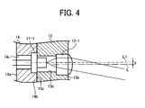
- Each of the coupling lenses 12-1 to 12-16 is, for example, a convex lens made of glass or plastic material, and is disposed in a through-hole 13c formed for the coupling lens supporter 13. As shown in FIG. 4 , a curvature center axis L of each of the coupling lenses 12-1 to 12-16 is offset with respect to an optical axis L1 of each of the light sources 11-1 to 11-16 toward the inner circumferential direction so that an axis deviation "d" is set between the curvature center axis L and the optical axis L1. In FIG. 1 , positions of the coupling lenses 12-1 to 12-9 and the light sources 11-1 to 11-9 are shown.
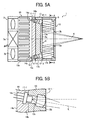
- the layout of the coupling lenses 12-1 to 12-16 and the light sources 11-1 to 11-16 can be designed, for example, as shown in FIGs. 5A and 5B .
- the optical axis of light exiting from the coupling lenses 12-1 to 12-16 can be angled with a given angle with respect to the first reflection mirror 10.
- FIG. 5B shows a positional relationship between the coupling lens 12-1 and the light source 11-1, which indicates a representative positional relationship of the coupling lenses and the light sources of the light source assembly.
- the optical axis of light exiting from the light source assembly can be angled with the given same angle with respect to the first reflection mirror 10.
- a light exiting from each of the light sources 11-1 to 11-16 passes through the corresponding coupling lenses 12-1 to 12-16 while a direction of the exiting light is angled with respect to the center of the circle ring pattern and the first reflection mirror 10.
- the lights exiting from the light sources 11-1 to 11-16 can be formed as an exit light having a substantially cone-shaped.
- the lights exiting from the light sources 11-1 to 11-16 can be focused at one portion without using a condensing lens, by which the number of parts can be reduced.
- the reflection mirror supporter 8, the coupling lens supporter 13, and the light source supporter 14 can be made of, for example, metal such as aluminum, or a mold resin.
- the reflection mirror supporter 8, the coupling lens supporter 13, and the light source supporter 14 can be formed as an integral part, or can be formed as separate parts and then assembled as one unit.
- the other side face 14b of the light source supporter 14 is attached to an attachment face 13d of the coupling lens supporter 13 ( FIG. 4 ).
- the first reflection mirror 10 is, for example, a parallel plate made of a glass plate, and includes a reflection mirror area indicated as a reflection face 10a, and a light passing area for passing light beams.
- the reflection face 10a can be formed by depositing an aluminum layer on one face of the first reflection mirror 10.
- the reflection face 10a may be also referred to the first reflection face 10a.
- the light passing area may, for example, be an opening part 10b set at the center portion of the first reflection mirror 10, wherein the opening part 10b is formed, for example, as a through-hole. Alternatively, the light passing area can formed without forming an opening such as a through-hole.
- the light passing area can be formed by depositing an aluminum layer on a glass plate while not depositing aluminum at a position corresponding to the opening part 10b, which means that the aluminum layer is formed with a ring pattern on the glass plate, and the center portion of the ring pattern not formed with the aluminum layer can be used as a transparent portion that can be used as the opening part 10b.
- the light passing area can be formed on the transparent plate, or can be formed as a through hole that the light can pass through, in which the transparent plate does not exist at the light passing area.
- the second reflection mirror 9 is made of, for example, a glass plate, and a reflection area is formed on one face of the plate by depositing, for example, an aluminum layer, by which the one face can be used as a reflection face 9a, which may be also referred to a second reflection face 9a.
- the second reflection mirror 9 is disposed at the front face 13b of the coupling lens supporter 13 facing the first reflection face 10a. As shown FIGs. 1 and 2 , the second reflection mirror 9 may be disposed in the concave portion 13a of the coupling lens supporter 13, wherein the concave portion 13a is the center portion of the coupling lens supporter 13, which is the inner side of the coupling lenses 12-1 to 12-16 arranged with a circle pattern.
- each of the coupling lenses 12-1 to 12-16 strikes and reflects on the first reflection mirror 10 and then returns toward the coupling lenses 12-1 to 12-16 side. Then, the light reflects on the second reflection mirror 9 disposed in the concave portion 13a that is the center portion (or inner side) of the coupling lenses 12-1 to 12-16, and then returns toward the first reflection mirror 10. The light reflection is repeated for a given number of times between the first reflection mirror 10 and the second reflection mirror 9, and then the light exits from the light passing area such as the opening part 10b formed at the center portion of the first reflection mirror 10.
- the light beams emitted from the plurality of light sources 11-1 to 11-16 and exiting from the coupling lenses 12-1 to 12-16 reflect for a given number of times, for example, a plurality of times between the first reflection mirror 10 and the second reflection mirror 9, and then synthesized as a light beam flux K while reducing its cross-section area, by which the light density of the light beam flux K can be increased, and thereby the light beam flux K having high light intensity can be emitted.
- the light beam emitted from each of the light sources 11-1 to 11-16 enters the first reflection mirror 10, which is a glass plate made of a mirror material with a given angle, and then reflects from the first reflection mirror 10. Because the light beams come closer to the center portion of the first reflection mirror 10 when the light beams reflect on the first reflection mirror 10, the light beams can be synthesized with a shorter distance. Further, by using the glass plate made of mirror material, a processing cost of the first reflection face 10a to reflect the light beams can be reduced.
- each of the light beam emitted from each of the light sources 11-1 to 11-16 reflects, for example, two times on the first reflection mirror 10 and the second reflection mirror 9 before outgoing from the light source apparatus 1, which means the number of reflection times of each light beam at each of the first reflection mirror 10 and the second reflection mirror 9 is respectively two times, but the number of reflection times of at each of the first reflection mirror 10 and the second reflection mirror 9 can be other value such as one, three, and so on, as required.
- the light source can be a combination of a laser element and a collimator lens, wherein the collimator lens converts the light emitted from the laser element to a parallel light or converging light.
- the light beams emitted from the light sources 11-1 to 11-16 can be focused at one portion without using a condensing lens, and thereby the number of parts can be reduced.
- FIGs. 6A and 6B are schematic view of a wind profile of the axial flow fan 3.
- a wind direction is indicated by an arrow
- an area of airflow in the axial flow fan 3 is indicated by a shaded area B.
- the wind speed discharged from the axial flow fan 3 becomes faster at the outer side and slower at the inner side, and further, the wind is a rotational flow flowing from the inner side to the outer side direction.
- the light sources 11-1 to 11-16 are arranged in a circle pattern in the light source supporter 14 so that the light sources 11-1 to 11-16 are positioned in an area corresponding to the area B shown in FIG. 6B .
- a pitch between each of the light sources can be set greater, by which heat interference among the light sources can be suppressed, and the wind can be directly hit to the light sources from the axial flow fan 3 effectively and efficiently, by which heat dissipation performance can be enhanced.
- the heat sink 15 can be disposed easily, and the axial flow fan 3 can send wind easily.
- the size of the light source supporter 14 and a diameter of a circle for arranging the plurality of light sources 11-1 to 11-16 can be set freely, the number of light sources can be set freely, and a supporter having a greater heat capacity can be used as the light source supporter 14 to enhance the heat dissipation performance.
- the light source apparatus 1 of the first example embodiment can implement the above described effects, and has a design freedom, by which the light source apparatus 1 can be used various needs.
- the light source apparatus 1 of the first example embodiment can be applied to, for example, an image projection apparatus such as a projector.
- FIG. 7 is the light source apparatus 1 having a plurality of light sources 11-1 to 11-16 and a plurality of coupling lenses 12-1 to 12-16 arranged in a polygon pattern such as a square pattern
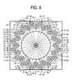
- FIG. 8 is the light source apparatus 1 having a plurality of light sources 11-1 to 11-32 and a plurality of coupling lenses 12-1 to 12-32 arranged in a double-circle pattern having the same center, which is one example of a multi-circle pattern.
- the multi-circle pattern can be a concentric rings pattern having the same center for each one of the circles composing the concentric rings. As shown in FIG.
- the light intensity can be further increased easily.
- the light sources 11-1 to 11-16 and the coupling lenses 12-1 to 12-16 are arranged in the double-circle pattern having the same center, which is an example of the concentric-circles pattern, but the circle pattern is not limited to the double-circle pattern.
- other concentric-circles pattern such as a triple-circle pattern, a quadruple-circle pattern, and so on can be employed.
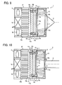
- FIGs. 9 and 10 are other example configurations of the light source apparatus 1 employing lenses having curvature for the light passing area of the first reflection mirror 10.
- FIG. 9 is the light source apparatus 1 attaching a convex lens 7 to the opening part 10b used as the light passing area
- FIG. 10 is the light source apparatus 1 attaching a concave lens 6 to the opening part 10b used as the light passing area.
- the configuration of FIG. 9 can reduce the number of reflection times between the first reflection mirror 10 and the second reflection mirror 9, and can set a shorter distance for condensing lights, and thereby the light intensity loss at the first reflection mirror 10 and the second reflection mirror 9 can be reduced, and further the light source apparatus 1 can be designed compact in size.
- the configuration of FIG. 10 can be used with a light intensity equalizing unit such as a rod integrator 16, which will be described later.
- the configuration of FIG. 10 can set an incidence angle to the rod integrator 16 smaller, by which the light intensity can be further equalized.
- the light beam reflects for a plurality of times between the first reflection mirror 10 and the second reflection mirror 9, but the number of reflection times between the first reflection mirror 10 and the second reflection mirror 9 can be set one time as shown in FIG. 12 , in which the light intensity loss at the first reflection mirror 10 and the second reflection mirror 9 can be reduced compared to a configuration reflecting the light beams for a plurality of times.
- the second reflector configured as the second reflection mirror 9 and the first reflector configured as the first reflection mirror 10 can be a single reflection mirror, but not limited hereto.
- the first reflector and the second reflector can be configured by combing a plurality of mirrors.
- FIG. 11 shows an image projection apparatus 2 employing the above described light source apparatus 1.
- the image projection apparatus 2 includes, for example, the light source apparatus 1, the rod integrator 16, an image generation panel 18, a relay lens 17, and a projection lens 19.
- the light source apparatus 1 includes, for example, the plurality of light sources 11-1 to 11-16, the plurality of coupling lenses 12-1 to 12-16, the first reflection mirror 10 using the center portion as the light passing area, the second reflection mirror 9, the light source supporter 14, the coupling lens supporter 13, the reflection mirror supporter 8, the heat sink 15, and the axial flow fan 3.
- the rod integrator 16 is used as a light intensity equalizing unit.
- the relay lens 17 is used as a light transmission optical system to transmit light equalized its light intensity by the rod integrator 16 to the image generation panel 18.
- the projection lens 19 is used as a projection optical system to enlarge and project an image generated by the image generation panel 18.
- the light beams emitted from the light sources 11-1 to 11-16 are condensed and then exit from the light source apparatus 1 as the light beam flux K.
- the light beam flux K enters the rod integrator 16, which equalizes light intensity of lights emitted from the light sources of the light source apparatus 1.
- the rod integrator 16 synthesizes color and equalizes the light intensity while the light beam flux K repeats the total reflection in the rod integrator 16, and then the light exits from the rod integrator 16.
- the image generation panel 18 may be a pass-through type panel that generates images based on modulation signals, but other devices such as a reflection type panel or a micro-mirror device panel can be used.
- the rod integrator 16 is an example of the light intensity equalizing unit, and other light intensity equalizing units can be used.
- the relay lens 17 is one example of the light transmission optical system
- the projection lens 19 is one example of the projection optical system.
- the light source apparatus 1, the rod integrator 16, the relay lens 17, and the image generation panel 18 can be collectively used as a display apparatus or device.
- the light beams emitted from a plurality of light sources can be synthesized as the light beam flux K having high light intensity and reduced its cross-section area, and the incidence angle to the rod integrator 16 can become smaller. Therefore, an area of the light radiating on the image generation panel 18 can be reduced, by which the projection lens 19 having a smaller numerical aperture (NA), which means a greater F-number lens, can be used. Therefore, the projection lens 19 can be designed and manufactured easily, and imaging performance can be maintained at a good enough level easily.
- the image projection apparatus 2 can use a plurality of light sources while enhancing the heat dissipation performance and the performance of equalizing the light intensity.
- the light beams reflected by the first reflection mirror 10 and the second reflection mirror 9 exit from the center portion of the first reflection mirror 10 as the light beam flux K, but the exit position (i.e., light passing area, opening part 10b) is not limited to the center portion of the first reflection mirror 10. Further, the position of the second reflection mirror 9 is not limited to the center portion of the coupling lens supporter 13, but can be changed depending on an exit direction and angle of light.
- a plurality of light sources can be disposed around the periphery of the second reflector such as the second reflection mirror 9 and a pitch of the light sources can be set greater, by which heat interference from other light sources can be suppressed. Further, the cooling air can directly hit the plurality of light sources effectively and efficiently, by which the heat dissipation performance can be enhanced. Further, because the light beams emitted from the plurality of light sources are reflected between a plurality of mirrors facing each other to synthesize the light beams, a distance for synthesizing the light beams can become shorter, by which the light source apparatus can be designed into compact.
- the plurality of light sources are arranged two dimensionally such as a plane with a given pitch, and the heat dissipation performance can be enhanced. Further, a cross-section area of the light beam flux composed of lights exiting from the plurality of light sources can be reduced, by which a compact light source apparatus and a compact image projection apparatus having the compact light source apparatus can be devised.
Landscapes
- Physics & Mathematics (AREA)
- General Physics & Mathematics (AREA)
- Engineering & Computer Science (AREA)
- General Engineering & Computer Science (AREA)
- Optics & Photonics (AREA)
- Projection Apparatus (AREA)
- Non-Portable Lighting Devices Or Systems Thereof (AREA)
- Arrangement Of Elements, Cooling, Sealing, Or The Like Of Lighting Devices (AREA)
Claims (14)
- Lichtquellenvorrichtung (1), die umfasst:einen ersten Reflektor (10) mit einer ersten Reflexionsfläche (10a);einen zweiten Reflektor (9) mit einer zweiten Reflexionsfläche (9a), wobei die zweite Reflexionsfläche (9a) des zweiten Reflektors (9) und die erste Reflexionsfläche (10a) des ersten Reflektors (10) einander gegenüberliegend angeordnet sind; undmehrere Lichtquellen (11), die um einen Umfang des zweiten Reflektors (9) angeordnet sind, wobei Lichtstrahlen, die von den mehreren Lichtquellen (11) ausgesendet werden, auf dem ersten Reflektor (10) reflektiert werden und dann auf dem zweiten Reflektor (9) reflektiert werden; undjede der Lichtquellen eine Kollimatorlinse (12) umfasst, die von der Lichtquelle ausgesendetes Licht in paralleles Licht oder konvergierendes Licht umsetzt; dadurch gekennzeichnet, dasseine Krümmungsmittelpunktachse (L) der Kollimatorlinse und eine optische Achse (L1) der Lichtquelle versetzt sind.
- Lichtquellenvorrichtung nach Anspruch 1, wobei die zweite Reflexionsfläche (9a) flach ist.
- Lichtquellenvorrichtung nach Anspruch 2, wobei die optische Achse des durch die Kollimatorlinse (12) ausgesendeten Lichts in Bezug auf den ersten Reflexionsspiegel abgewinkelt ist.
- Lichtquellenvorrichtung nach Anspruch 3, wobei die erste Reflexionsfläche (10a) flach ist; und durch die Kollimatorlinse ausgesendetes Licht durch den ersten Reflexionsspiegel (10) zu dem zweiten Reflexionsspiegel (9) reflektiert wird und dann durch den zweiten Reflexionsspiegel (9) in Richtung des ersten Reflexionsspiegels (10) reflektiert wird.
- Lichtquellenvorrichtung (1) nach einem der Ansprüche 1 bis 4, wobei die mehreren Lichtquellen (11) in einem im Wesentlichen kreisförmigen Muster oder einem Polygonmuster um den Umfang des zweiten Reflektors (9) angeordnet sind,
wobei der erste Reflektor (10) an einer Ausgangsrichtung der von den mehreren Lichtquellen (11) ausgesendeten Lichtstrahlen angeordnet ist und der ersten Reflektor (10) die erste Reflexionsfläche (10a) als eine Spiegelfläche, um den von jeder der Lichtquellen (11) ausgesendeten Lichtstrahl zu der Lichtquellenseite (11) zu reflektieren, und einen Lichtdurchgangsbereich (10b), um durch einen Lichtstrahlfluss hindurchzuführen, enthält,
wobei der zweite Reflektor (9), der gegenüber dem ersten Reflektor (10) angeordnet ist, die durch die mehreren Lichtquellen (11) ausgesendeten Lichtstrahlen zu der ersten Reflexionsfläche (10a) des ersten Reflektors (10) reflektiert,
wobei der Lichtstrahlfluss aus dem Lichtdurchgangsbereich (10b) austritt, nachdem er zwischen dem ersten Reflektor (10) und dem zweiten Reflektor (9) reflektiert wurde. - Lichtquellenvorrichtung (1) nach Anspruch 5, wobei der Lichtdurchgangsbereich (10b) des ersten Reflektors (10) eine lichtdurchlässige parallele Platte ist.
- Lichtquellenvorrichtung (1) nach Anspruch 5, wobei der Lichtdurchgangsbereich (10b) des ersten Reflektors (10) eine Linse mit einer Krümmung ist.
- Lichtquellenvorrichtung (1) nach einem der Ansprüche 1 bis 7, wobei jede der mehreren Lichtquellen (11) eine optische Achse für von jeder der mehreren Lichtquellen ausgesendetes Licht hat und die optischen Achsen der mehreren Lichtquellen (11) in Bezug auf den ersten Reflektor (10) unter demselben Winkel abgewinkelt sind.
- Lichtquellenvorrichtung (1) nach einem der Ansprüche 1 bis 8, wobei jede der mehreren Lichtquellen (11) ein Laserelement enthält.
- Lichtquellenvorrichtung (1) nach einem der Ansprüche 1 bis 9, wobei die mehreren Lichtquellen (11) in konzentrischen Ringen angeordnet sind.
- Lichtquellenvorrichtung (1) nach einem der Ansprüche 1 bis 10, die ferner umfasst:einen Wärmeableitkörper, der an einem Träger befestigt ist, der die mehreren Lichtquellen trägt; undeinen Ventilator, um Luft zu dem Wärmeableitkörper zu schicken, um den Wärmeableitkörper zu kühlen.
- Lichtquellenvorrichtung (1) nach Anspruch 11, wobei die mehreren Lichtquellen (11) zumindest teilweise an einem Abschnitt angeordnet sind, an dem der Ventilator Luft zuführt.
- Bildprojektionsvorrichtung (2), die umfasst:die Lichtquellenvorrichtung (1) nach einem der Ansprüche 1 bis 12;eine Lichtstärkenangleichungseinheit (16), um die Lichtstärken des von jeder der Lichtquellen der Lichtquellenvorrichtung kommenden Lichts einander anzugleichen;ein optisches Lichtübertragungssystem (17), um ausgehendes Licht, dessen Lichtstärke durch die Lichtstärkenangleichungseinheit (16) angeglichen wurde, an eine Bilderzeugungstafel (18) zu senden; undein optisches Projektionssystem (19), um ein durch die Bilderzeugungstafel (18) erzeugtes Bild zu vergrößern und zu projizieren.
- Anzeigevorrichtung, die umfasst:die Lichtquellenvorrichtung (1) nach einem der Ansprüche 1 bis 12;eine Lichtstärkenangleichungseinheit (16), um die Lichtstärken des von jeder der Lichtquellen der Lichtquellenvorrichtung kommenden Lichts einander anzugleichen;eine Bilderzeugungstafel (18), um ein Bild unter Verwendung des Lichts einer jeden der Lichtquellen zu erzeugen;ein optisches Lichtübertragungssystem (17), um ausgehendes Licht, dessen Lichtstärke durch die Lichtstärkenangleichungseinheit (16) angeglichen wurde, an die Bilderzeugungstafel (18) zu übertragen.
Applications Claiming Priority (2)
| Application Number | Priority Date | Filing Date | Title |
|---|---|---|---|
| JP2012114923 | 2012-05-18 | ||
| JP2013048137 | 2013-03-11 |
Publications (2)
| Publication Number | Publication Date |
|---|---|
| EP2664958A1 EP2664958A1 (de) | 2013-11-20 |
| EP2664958B1 true EP2664958B1 (de) | 2015-10-28 |
Family
ID=48468130
Family Applications (1)
| Application Number | Title | Priority Date | Filing Date |
|---|---|---|---|
| EP13165397.4A Not-in-force EP2664958B1 (de) | 2012-05-18 | 2013-04-25 | Lichtquellenvorrichtung und Bildprojektionsvorrichtung |
Country Status (4)
| Country | Link |
|---|---|
| US (1) | US20130308104A1 (de) |
| EP (1) | EP2664958B1 (de) |
| JP (1) | JP6260107B2 (de) |
| CN (1) | CN103424973A (de) |
Families Citing this family (30)
| Publication number | Priority date | Publication date | Assignee | Title |
|---|---|---|---|---|
| JP6311219B2 (ja) * | 2012-07-26 | 2018-04-18 | 株式会社リコー | 照明光形成装置、照明光源装置および画像表示装置 |
| JP6168387B2 (ja) | 2013-02-26 | 2017-07-26 | 株式会社リコー | 光源装置及びこれを備えた画像投射装置 |
| JP6179792B2 (ja) | 2013-02-26 | 2017-08-16 | 株式会社リコー | 光源装置及びこれを備えた画像投射装置 |
| JP6236811B2 (ja) | 2013-03-14 | 2017-11-29 | 株式会社リコー | 光源ユニット並びに照明装置及び画像投射装置 |
| JP6349784B2 (ja) * | 2013-03-14 | 2018-07-04 | 株式会社リコー | 光源ユニット並びに照明装置及び画像投射装置 |
| TW201439661A (zh) * | 2013-04-10 | 2014-10-16 | Delta Electronics Inc | 光源模組及其所適用之投影裝置 |
| JP6233687B2 (ja) | 2013-08-12 | 2017-11-22 | 株式会社リコー | 光源装置及びこれを備えた画像投射装置 |
| JP6452027B2 (ja) | 2013-10-23 | 2019-01-16 | 株式会社リコー | 光源装置及びこれを備えた画像投射装置 |
| JP6476667B2 (ja) | 2013-11-01 | 2019-03-06 | 株式会社リコー | 光源装置及びこれを用いたプロジェクタ |
| WO2015122075A1 (ja) | 2014-02-17 | 2015-08-20 | 株式会社リコー | 光照射装置及びこれを備えた画像表示装置 |
| EP3121649B1 (de) | 2014-03-18 | 2019-12-18 | Ricoh Company, Ltd. | Lichtquellenvorrichtung und bildprojektionsvorrichtung mit lichtquellenvorrichtung |
| CN106133598B (zh) * | 2014-04-08 | 2018-09-21 | 索尼公司 | 光源设备和图像显示设备 |
| JP6547270B2 (ja) | 2014-10-10 | 2019-07-24 | 株式会社リコー | 光源装置及びこの光源装置を有する画像投影装置 |
| FR3034497B1 (fr) * | 2015-04-03 | 2020-02-07 | Xyzed | Source de lumiere monochromatique a diodes |
| DE102015206341A1 (de) * | 2015-04-09 | 2016-10-13 | Sirona Dental Systems Gmbh | Verfahren und ein Vermessungssystem zur optischen Vermessung eines Objekts |
| JP6206560B2 (ja) | 2015-09-28 | 2017-10-04 | 株式会社リコー | システム |
| JP6701732B2 (ja) * | 2015-12-29 | 2020-05-27 | セイコーエプソン株式会社 | 光源装置、照明装置及びプロジェクター |
| CN108885388B (zh) * | 2016-04-04 | 2021-10-19 | 索尼公司 | 光源装置和图像显示装置 |
| JP6821990B2 (ja) * | 2016-07-26 | 2021-01-27 | セイコーエプソン株式会社 | 照明装置およびプロジェクター |
| JP6681808B2 (ja) * | 2016-09-12 | 2020-04-15 | マクセル株式会社 | 光源装置 |
| CN107861322A (zh) * | 2016-09-22 | 2018-03-30 | 上海激亮光电科技有限公司 | 一种高效激光照明系统 |
| US20180100635A1 (en) * | 2016-10-07 | 2018-04-12 | Christie Digital Systems Usa, Inc. | Apparatus for combining light beams |
| TWI625589B (zh) * | 2017-03-27 | 2018-06-01 | 晶睿通訊股份有限公司 | 燈杯及攝影機 |
| CN110345394A (zh) * | 2018-04-04 | 2019-10-18 | 深圳市Tcl高新技术开发有限公司 | 一种光收集装置 |
| JP7268421B2 (ja) | 2019-03-18 | 2023-05-08 | 株式会社リコー | 光源光学系、光源装置及び画像投射装置 |
| CN111722465A (zh) | 2019-03-20 | 2020-09-29 | 株式会社理光 | 光源装置、图像投影装置和光源光学系统 |
| KR102385020B1 (ko) * | 2020-02-17 | 2022-04-14 | 주식회사 라이다스 | 레이저 스캐닝 시스템용 광학계 |
| JP6813118B2 (ja) * | 2020-05-07 | 2021-01-13 | セイコーエプソン株式会社 | 照明装置及びプロジェクター |
| JP7107351B2 (ja) * | 2020-12-17 | 2022-07-27 | セイコーエプソン株式会社 | 照明装置及びプロジェクター |
| WO2024075209A1 (ja) * | 2022-10-05 | 2024-04-11 | シャープNecディスプレイソリューションズ株式会社 | 光源装置及びプロジェクタ |
Family Cites Families (25)
| Publication number | Priority date | Publication date | Assignee | Title |
|---|---|---|---|---|
| US5383168A (en) * | 1993-04-01 | 1995-01-17 | Eastman Kodak Company | Actively athermalized optical head assembly |
| US6351453B1 (en) * | 1998-03-26 | 2002-02-26 | Bell Atlantic Network Services, Inc. | Internet service provider (ISP) finder |
| JP4681098B2 (ja) * | 2000-04-18 | 2011-05-11 | 日東光学株式会社 | 映像プロジェクタ |
| US6425677B1 (en) * | 2001-02-20 | 2002-07-30 | Prokia Technology Co., Ltd. | Illuminating apparatus using multiple light sources |
| KR100450815B1 (ko) * | 2002-02-01 | 2004-10-01 | 삼성전자주식회사 | 조명계 및 이를 채용한 프로젝션 디스플레이 장치 |
| JP2004013107A (ja) * | 2002-06-11 | 2004-01-15 | Olympus Corp | 照明光学素子 |
| EP1403695A1 (de) * | 2002-09-24 | 2004-03-31 | Agfa-Gevaert AG | Vorrichtung zum Aufbelichten einer Vorlage mittels einer Vielzahl homogenisierter und überlagerter Punktlichtquellen |
| GB0420233D0 (en) * | 2004-09-11 | 2004-10-13 | Power Projector Ltd | Efficient light engine for projection application |
| US7226188B2 (en) * | 2004-11-19 | 2007-06-05 | Whiterock Design, Llc | Stage lighting methods and apparatus |
| KR100683171B1 (ko) * | 2005-03-08 | 2007-02-15 | 삼성전자주식회사 | 방열장치 및 그것을 구비하는 프로젝터 |
| JP2006251149A (ja) * | 2005-03-09 | 2006-09-21 | Fujinon Corp | 照明装置及び投写型画像表示装置。 |
| DE102006044019B4 (de) * | 2006-09-15 | 2011-12-29 | Stiftung Alfred-Wegener-Institut für Polar- und Meeresforschung Stiftung des öffentlichen Rechts | Reflektorstrahler |
| WO2008047851A1 (en) * | 2006-10-12 | 2008-04-24 | Panasonic Corporation | Light-emitting apparatus |
| JP2008203093A (ja) * | 2007-02-20 | 2008-09-04 | Mitsutoyo Corp | 照明装置、画像測定装置 |
| JP4538674B2 (ja) * | 2007-07-26 | 2010-09-08 | 株式会社オプトデザイン | 面照明ユニット、面照明光源装置、面照明装置および面照明ユニットの製造用展開基板 |
| WO2009082737A1 (en) * | 2007-12-24 | 2009-07-02 | Columbia Insurance Company | System for representing colors including an integrating light capsule |
| DE102008006249B4 (de) * | 2008-01-25 | 2011-04-28 | Lanz, Rüdiger | Motorisch beweglicher, kopfbewegter Scheinwerfer |
| JP5315845B2 (ja) * | 2008-08-07 | 2013-10-16 | 株式会社リコー | 照明装置及び投影型画像表示装置 |
| CN201429765Y (zh) * | 2009-04-15 | 2010-03-24 | 深圳高迪数码有限公司 | Lcos投影机led散热结构 |
| JP4711155B2 (ja) | 2009-06-30 | 2011-06-29 | カシオ計算機株式会社 | 光源装置及びプロジェクタ |
| CN102472897B (zh) * | 2009-07-13 | 2014-10-22 | 马丁专业公司 | 颜色-组合照明装置 |
| JP5166580B2 (ja) * | 2010-08-06 | 2013-03-21 | ポスコ アイシーティ カンパニー リミテッド | 光半導体照明装置 |
| US8858040B2 (en) * | 2010-08-23 | 2014-10-14 | Cooliance, Inc. | Cooling methodology for high brightness light emitting diodes |
| JP5601097B2 (ja) * | 2010-09-01 | 2014-10-08 | 株式会社リコー | 照射用装置およびプロジェクタ装置 |
| US20130077283A1 (en) * | 2011-09-23 | 2013-03-28 | Lin Li | Apparatuses and methods for high-efficiency polarization conversion in a projection light engine |
-
2013
- 2013-04-25 EP EP13165397.4A patent/EP2664958B1/de not_active Not-in-force
- 2013-04-29 US US13/872,490 patent/US20130308104A1/en not_active Abandoned
- 2013-05-10 CN CN2013101701682A patent/CN103424973A/zh active Pending
- 2013-05-13 JP JP2013101515A patent/JP6260107B2/ja not_active Expired - Fee Related
Also Published As
| Publication number | Publication date |
|---|---|
| EP2664958A1 (de) | 2013-11-20 |
| CN103424973A (zh) | 2013-12-04 |
| JP2014199790A (ja) | 2014-10-23 |
| JP6260107B2 (ja) | 2018-01-17 |
| US20130308104A1 (en) | 2013-11-21 |
Similar Documents
| Publication | Publication Date | Title |
|---|---|---|
| EP2664958B1 (de) | Lichtquellenvorrichtung und Bildprojektionsvorrichtung | |
| US9250504B2 (en) | Light source unit and image projection apparatus including light source unit | |
| US9557631B2 (en) | Light source unit and image projection apparatus including light source unit | |
| EP2698661B1 (de) | Beleuchtungslichterzeugungsvorrichtung | |
| US9857672B2 (en) | Light source unit, lighting apparatus and image projection apparatus | |
| US9354498B2 (en) | Light source unit, lighting apparatus and image projection apparatus | |
| JP6178991B2 (ja) | 光源ユニットおよびそれを用いた光源モジュール | |
| JP2007080565A (ja) | 光源装置およびアレイ光源装置 | |
| JP2018055054A (ja) | 回転冷却装置、波長変換装置、光拡散装置、光源装置及びプロジェクター | |
| JP2018155860A (ja) | 冷却装置、光源装置及び投影装置 | |
| JP2015052791A (ja) | 光源装置及びプロジェクタ | |
| JP6351090B2 (ja) | 光源ユニット、光源ユニットを用いた照明光学系 | |
| WO2013118272A1 (ja) | 照明光学系および投写型表示装置 | |
| JP6696297B2 (ja) | 投射装置 | |
| JP7499559B2 (ja) | 冷却装置、光源装置及び投影装置 | |
| JP2018063448A (ja) | 光源装置及び投影装置 | |
| JP6489161B2 (ja) | 画像投射装置 | |
| TWI334058B (en) | Projection system | |
| JP2007227690A (ja) | リフレクターとそれを用いた発光モジュール | |
| JP2011203519A (ja) | 冷却装置及びプロジェクター |
Legal Events
| Date | Code | Title | Description |
|---|---|---|---|
| PUAI | Public reference made under article 153(3) epc to a published international application that has entered the european phase |
Free format text: ORIGINAL CODE: 0009012 |
|
| 17P | Request for examination filed |
Effective date: 20130425 |
|
| AK | Designated contracting states |
Kind code of ref document: A1 Designated state(s): AL AT BE BG CH CY CZ DE DK EE ES FI FR GB GR HR HU IE IS IT LI LT LU LV MC MK MT NL NO PL PT RO RS SE SI SK SM TR |
|
| AX | Request for extension of the european patent |
Extension state: BA ME |
|
| REG | Reference to a national code |
Ref country code: DE Ref legal event code: R079 Ref document number: 602013003627 Country of ref document: DE Free format text: PREVIOUS MAIN CLASS: G03B0021200000 Ipc: F21V0007000000 |
|
| RIC1 | Information provided on ipc code assigned before grant |
Ipc: G03B 21/16 20060101ALN20150409BHEP Ipc: F21V 7/00 20060101AFI20150409BHEP Ipc: G02B 27/10 20060101ALI20150409BHEP Ipc: G03B 21/20 20060101ALI20150409BHEP |
|
| GRAP | Despatch of communication of intention to grant a patent |
Free format text: ORIGINAL CODE: EPIDOSNIGR1 |
|
| INTG | Intention to grant announced |
Effective date: 20150528 |
|
| GRAS | Grant fee paid |
Free format text: ORIGINAL CODE: EPIDOSNIGR3 |
|
| GRAA | (expected) grant |
Free format text: ORIGINAL CODE: 0009210 |
|
| AK | Designated contracting states |
Kind code of ref document: B1 Designated state(s): AL AT BE BG CH CY CZ DE DK EE ES FI FR GB GR HR HU IE IS IT LI LT LU LV MC MK MT NL NO PL PT RO RS SE SI SK SM TR |
|
| REG | Reference to a national code |
Ref country code: GB Ref legal event code: FG4D |
|
| REG | Reference to a national code |
Ref country code: CH Ref legal event code: EP |
|
| REG | Reference to a national code |
Ref country code: AT Ref legal event code: REF Ref document number: 758156 Country of ref document: AT Kind code of ref document: T Effective date: 20151115 |
|
| REG | Reference to a national code |
Ref country code: IE Ref legal event code: FG4D |
|
| REG | Reference to a national code |
Ref country code: DE Ref legal event code: R096 Ref document number: 602013003627 Country of ref document: DE |
|
| REG | Reference to a national code |
Ref country code: LT Ref legal event code: MG4D |
|
| REG | Reference to a national code |
Ref country code: NL Ref legal event code: MP Effective date: 20151028 |
|
| REG | Reference to a national code |
Ref country code: AT Ref legal event code: MK05 Ref document number: 758156 Country of ref document: AT Kind code of ref document: T Effective date: 20151028 |
|
| REG | Reference to a national code |
Ref country code: FR Ref legal event code: PLFP Year of fee payment: 4 |
|
| PG25 | Lapsed in a contracting state [announced via postgrant information from national office to epo] |
Ref country code: HR Free format text: LAPSE BECAUSE OF FAILURE TO SUBMIT A TRANSLATION OF THE DESCRIPTION OR TO PAY THE FEE WITHIN THE PRESCRIBED TIME-LIMIT Effective date: 20151028 Ref country code: NO Free format text: LAPSE BECAUSE OF FAILURE TO SUBMIT A TRANSLATION OF THE DESCRIPTION OR TO PAY THE FEE WITHIN THE PRESCRIBED TIME-LIMIT Effective date: 20160128 Ref country code: NL Free format text: LAPSE BECAUSE OF FAILURE TO SUBMIT A TRANSLATION OF THE DESCRIPTION OR TO PAY THE FEE WITHIN THE PRESCRIBED TIME-LIMIT Effective date: 20151028 Ref country code: IS Free format text: LAPSE BECAUSE OF FAILURE TO SUBMIT A TRANSLATION OF THE DESCRIPTION OR TO PAY THE FEE WITHIN THE PRESCRIBED TIME-LIMIT Effective date: 20160228 Ref country code: IT Free format text: LAPSE BECAUSE OF FAILURE TO SUBMIT A TRANSLATION OF THE DESCRIPTION OR TO PAY THE FEE WITHIN THE PRESCRIBED TIME-LIMIT Effective date: 20151028 Ref country code: ES Free format text: LAPSE BECAUSE OF FAILURE TO SUBMIT A TRANSLATION OF THE DESCRIPTION OR TO PAY THE FEE WITHIN THE PRESCRIBED TIME-LIMIT Effective date: 20151028 Ref country code: LT Free format text: LAPSE BECAUSE OF FAILURE TO SUBMIT A TRANSLATION OF THE DESCRIPTION OR TO PAY THE FEE WITHIN THE PRESCRIBED TIME-LIMIT Effective date: 20151028 |
|
| PG25 | Lapsed in a contracting state [announced via postgrant information from national office to epo] |
Ref country code: SE Free format text: LAPSE BECAUSE OF FAILURE TO SUBMIT A TRANSLATION OF THE DESCRIPTION OR TO PAY THE FEE WITHIN THE PRESCRIBED TIME-LIMIT Effective date: 20151028 Ref country code: LV Free format text: LAPSE BECAUSE OF FAILURE TO SUBMIT A TRANSLATION OF THE DESCRIPTION OR TO PAY THE FEE WITHIN THE PRESCRIBED TIME-LIMIT Effective date: 20151028 Ref country code: AT Free format text: LAPSE BECAUSE OF FAILURE TO SUBMIT A TRANSLATION OF THE DESCRIPTION OR TO PAY THE FEE WITHIN THE PRESCRIBED TIME-LIMIT Effective date: 20151028 Ref country code: FI Free format text: LAPSE BECAUSE OF FAILURE TO SUBMIT A TRANSLATION OF THE DESCRIPTION OR TO PAY THE FEE WITHIN THE PRESCRIBED TIME-LIMIT Effective date: 20151028 Ref country code: PT Free format text: LAPSE BECAUSE OF FAILURE TO SUBMIT A TRANSLATION OF THE DESCRIPTION OR TO PAY THE FEE WITHIN THE PRESCRIBED TIME-LIMIT Effective date: 20160229 Ref country code: PL Free format text: LAPSE BECAUSE OF FAILURE TO SUBMIT A TRANSLATION OF THE DESCRIPTION OR TO PAY THE FEE WITHIN THE PRESCRIBED TIME-LIMIT Effective date: 20151028 Ref country code: RS Free format text: LAPSE BECAUSE OF FAILURE TO SUBMIT A TRANSLATION OF THE DESCRIPTION OR TO PAY THE FEE WITHIN THE PRESCRIBED TIME-LIMIT Effective date: 20151028 Ref country code: GR Free format text: LAPSE BECAUSE OF FAILURE TO SUBMIT A TRANSLATION OF THE DESCRIPTION OR TO PAY THE FEE WITHIN THE PRESCRIBED TIME-LIMIT Effective date: 20160129 |
|
| PG25 | Lapsed in a contracting state [announced via postgrant information from national office to epo] |
Ref country code: CZ Free format text: LAPSE BECAUSE OF FAILURE TO SUBMIT A TRANSLATION OF THE DESCRIPTION OR TO PAY THE FEE WITHIN THE PRESCRIBED TIME-LIMIT Effective date: 20151028 |
|
| REG | Reference to a national code |
Ref country code: DE Ref legal event code: R097 Ref document number: 602013003627 Country of ref document: DE |
|
| PG25 | Lapsed in a contracting state [announced via postgrant information from national office to epo] |
Ref country code: SK Free format text: LAPSE BECAUSE OF FAILURE TO SUBMIT A TRANSLATION OF THE DESCRIPTION OR TO PAY THE FEE WITHIN THE PRESCRIBED TIME-LIMIT Effective date: 20151028 Ref country code: RO Free format text: LAPSE BECAUSE OF FAILURE TO SUBMIT A TRANSLATION OF THE DESCRIPTION OR TO PAY THE FEE WITHIN THE PRESCRIBED TIME-LIMIT Effective date: 20151028 Ref country code: DK Free format text: LAPSE BECAUSE OF FAILURE TO SUBMIT A TRANSLATION OF THE DESCRIPTION OR TO PAY THE FEE WITHIN THE PRESCRIBED TIME-LIMIT Effective date: 20151028 Ref country code: EE Free format text: LAPSE BECAUSE OF FAILURE TO SUBMIT A TRANSLATION OF THE DESCRIPTION OR TO PAY THE FEE WITHIN THE PRESCRIBED TIME-LIMIT Effective date: 20151028 Ref country code: BE Free format text: LAPSE BECAUSE OF NON-PAYMENT OF DUE FEES Effective date: 20160430 Ref country code: SM Free format text: LAPSE BECAUSE OF FAILURE TO SUBMIT A TRANSLATION OF THE DESCRIPTION OR TO PAY THE FEE WITHIN THE PRESCRIBED TIME-LIMIT Effective date: 20151028 |
|
| PLBE | No opposition filed within time limit |
Free format text: ORIGINAL CODE: 0009261 |
|
| STAA | Information on the status of an ep patent application or granted ep patent |
Free format text: STATUS: NO OPPOSITION FILED WITHIN TIME LIMIT |
|
| 26N | No opposition filed |
Effective date: 20160729 |
|
| PG25 | Lapsed in a contracting state [announced via postgrant information from national office to epo] |
Ref country code: SI Free format text: LAPSE BECAUSE OF FAILURE TO SUBMIT A TRANSLATION OF THE DESCRIPTION OR TO PAY THE FEE WITHIN THE PRESCRIBED TIME-LIMIT Effective date: 20151028 |
|
| REG | Reference to a national code |
Ref country code: CH Ref legal event code: PL |
|
| PG25 | Lapsed in a contracting state [announced via postgrant information from national office to epo] |
Ref country code: LU Free format text: LAPSE BECAUSE OF FAILURE TO SUBMIT A TRANSLATION OF THE DESCRIPTION OR TO PAY THE FEE WITHIN THE PRESCRIBED TIME-LIMIT Effective date: 20160425 Ref country code: BE Free format text: LAPSE BECAUSE OF FAILURE TO SUBMIT A TRANSLATION OF THE DESCRIPTION OR TO PAY THE FEE WITHIN THE PRESCRIBED TIME-LIMIT Effective date: 20151028 |
|
| REG | Reference to a national code |
Ref country code: IE Ref legal event code: MM4A |
|
| PG25 | Lapsed in a contracting state [announced via postgrant information from national office to epo] |
Ref country code: LI Free format text: LAPSE BECAUSE OF NON-PAYMENT OF DUE FEES Effective date: 20160430 Ref country code: CH Free format text: LAPSE BECAUSE OF NON-PAYMENT OF DUE FEES Effective date: 20160430 |
|
| REG | Reference to a national code |
Ref country code: FR Ref legal event code: PLFP Year of fee payment: 5 |
|
| PG25 | Lapsed in a contracting state [announced via postgrant information from national office to epo] |
Ref country code: IE Free format text: LAPSE BECAUSE OF NON-PAYMENT OF DUE FEES Effective date: 20160425 |
|
| REG | Reference to a national code |
Ref country code: FR Ref legal event code: PLFP Year of fee payment: 6 |
|
| PG25 | Lapsed in a contracting state [announced via postgrant information from national office to epo] |
Ref country code: HU Free format text: LAPSE BECAUSE OF FAILURE TO SUBMIT A TRANSLATION OF THE DESCRIPTION OR TO PAY THE FEE WITHIN THE PRESCRIBED TIME-LIMIT; INVALID AB INITIO Effective date: 20130425 Ref country code: CY Free format text: LAPSE BECAUSE OF FAILURE TO SUBMIT A TRANSLATION OF THE DESCRIPTION OR TO PAY THE FEE WITHIN THE PRESCRIBED TIME-LIMIT Effective date: 20151028 |
|
| PG25 | Lapsed in a contracting state [announced via postgrant information from national office to epo] |
Ref country code: TR Free format text: LAPSE BECAUSE OF FAILURE TO SUBMIT A TRANSLATION OF THE DESCRIPTION OR TO PAY THE FEE WITHIN THE PRESCRIBED TIME-LIMIT Effective date: 20151028 Ref country code: MC Free format text: LAPSE BECAUSE OF FAILURE TO SUBMIT A TRANSLATION OF THE DESCRIPTION OR TO PAY THE FEE WITHIN THE PRESCRIBED TIME-LIMIT Effective date: 20151028 Ref country code: MK Free format text: LAPSE BECAUSE OF FAILURE TO SUBMIT A TRANSLATION OF THE DESCRIPTION OR TO PAY THE FEE WITHIN THE PRESCRIBED TIME-LIMIT Effective date: 20151028 Ref country code: MT Free format text: LAPSE BECAUSE OF NON-PAYMENT OF DUE FEES Effective date: 20160430 |
|
| PG25 | Lapsed in a contracting state [announced via postgrant information from national office to epo] |
Ref country code: BG Free format text: LAPSE BECAUSE OF FAILURE TO SUBMIT A TRANSLATION OF THE DESCRIPTION OR TO PAY THE FEE WITHIN THE PRESCRIBED TIME-LIMIT Effective date: 20151028 |
|
| PG25 | Lapsed in a contracting state [announced via postgrant information from national office to epo] |
Ref country code: AL Free format text: LAPSE BECAUSE OF FAILURE TO SUBMIT A TRANSLATION OF THE DESCRIPTION OR TO PAY THE FEE WITHIN THE PRESCRIBED TIME-LIMIT Effective date: 20151028 |
|
| PGFP | Annual fee paid to national office [announced via postgrant information from national office to epo] |
Ref country code: GB Payment date: 20220425 Year of fee payment: 10 Ref country code: FR Payment date: 20220421 Year of fee payment: 10 Ref country code: DE Payment date: 20220420 Year of fee payment: 10 |
|
| REG | Reference to a national code |
Ref country code: DE Ref legal event code: R119 Ref document number: 602013003627 Country of ref document: DE |
|
| GBPC | Gb: european patent ceased through non-payment of renewal fee |
Effective date: 20230425 |
|
| PG25 | Lapsed in a contracting state [announced via postgrant information from national office to epo] |
Ref country code: GB Free format text: LAPSE BECAUSE OF NON-PAYMENT OF DUE FEES Effective date: 20230425 |
|
| PG25 | Lapsed in a contracting state [announced via postgrant information from national office to epo] |
Ref country code: GB Free format text: LAPSE BECAUSE OF NON-PAYMENT OF DUE FEES Effective date: 20230425 Ref country code: FR Free format text: LAPSE BECAUSE OF NON-PAYMENT OF DUE FEES Effective date: 20230430 Ref country code: DE Free format text: LAPSE BECAUSE OF NON-PAYMENT OF DUE FEES Effective date: 20231103 |