EP2664659A1 - Antifog-Beschichtung - Google Patents
Antifog-Beschichtung Download PDFInfo
- Publication number
- EP2664659A1 EP2664659A1 EP13167633.0A EP13167633A EP2664659A1 EP 2664659 A1 EP2664659 A1 EP 2664659A1 EP 13167633 A EP13167633 A EP 13167633A EP 2664659 A1 EP2664659 A1 EP 2664659A1
- Authority
- EP
- European Patent Office
- Prior art keywords
- optical component
- group
- poly
- meth
- acrylate
- Prior art date
- Legal status (The legal status is an assumption and is not a legal conclusion. Google has not performed a legal analysis and makes no representation as to the accuracy of the status listed.)
- Granted
Links
Images

Classifications
-
- G—PHYSICS
- G02—OPTICS
- G02B—OPTICAL ELEMENTS, SYSTEMS OR APPARATUS
- G02B1/00—Optical elements characterised by the material of which they are made; Optical coatings for optical elements
- G02B1/10—Optical coatings produced by application to, or surface treatment of, optical elements
- G02B1/18—Coatings for keeping optical surfaces clean, e.g. hydrophobic or photo-catalytic films
-
- C—CHEMISTRY; METALLURGY
- C03—GLASS; MINERAL OR SLAG WOOL
- C03C—CHEMICAL COMPOSITION OF GLASSES, GLAZES OR VITREOUS ENAMELS; SURFACE TREATMENT OF GLASS; SURFACE TREATMENT OF FIBRES OR FILAMENTS MADE FROM GLASS, MINERALS OR SLAGS; JOINING GLASS TO GLASS OR OTHER MATERIALS
- C03C17/00—Surface treatment of glass, not in the form of fibres or filaments, by coating
- C03C17/28—Surface treatment of glass, not in the form of fibres or filaments, by coating with organic material
- C03C17/30—Surface treatment of glass, not in the form of fibres or filaments, by coating with organic material with silicon-containing compounds
-
- C—CHEMISTRY; METALLURGY
- C03—GLASS; MINERAL OR SLAG WOOL
- C03C—CHEMICAL COMPOSITION OF GLASSES, GLAZES OR VITREOUS ENAMELS; SURFACE TREATMENT OF GLASS; SURFACE TREATMENT OF FIBRES OR FILAMENTS MADE FROM GLASS, MINERALS OR SLAGS; JOINING GLASS TO GLASS OR OTHER MATERIALS
- C03C17/00—Surface treatment of glass, not in the form of fibres or filaments, by coating
- C03C17/34—Surface treatment of glass, not in the form of fibres or filaments, by coating with at least two coatings having different compositions
-
- C—CHEMISTRY; METALLURGY
- C09—DYES; PAINTS; POLISHES; NATURAL RESINS; ADHESIVES; COMPOSITIONS NOT OTHERWISE PROVIDED FOR; APPLICATIONS OF MATERIALS NOT OTHERWISE PROVIDED FOR
- C09D—COATING COMPOSITIONS, e.g. PAINTS, VARNISHES OR LACQUERS; FILLING PASTES; CHEMICAL PAINT OR INK REMOVERS; INKS; CORRECTING FLUIDS; WOODSTAINS; PASTES OR SOLIDS FOR COLOURING OR PRINTING; USE OF MATERIALS THEREFOR
- C09D133/00—Coating compositions based on homopolymers or copolymers of compounds having one or more unsaturated aliphatic radicals, each having only one carbon-to-carbon double bond, and at least one being terminated by only one carboxyl radical, or of salts, anhydrides, esters, amides, imides, or nitriles thereof; Coating compositions based on derivatives of such polymers
- C09D133/04—Homopolymers or copolymers of esters
- C09D133/14—Homopolymers or copolymers of esters of esters containing halogen, nitrogen, sulfur or oxygen atoms in addition to the carboxy oxygen
-
- C—CHEMISTRY; METALLURGY
- C09—DYES; PAINTS; POLISHES; NATURAL RESINS; ADHESIVES; COMPOSITIONS NOT OTHERWISE PROVIDED FOR; APPLICATIONS OF MATERIALS NOT OTHERWISE PROVIDED FOR
- C09D—COATING COMPOSITIONS, e.g. PAINTS, VARNISHES OR LACQUERS; FILLING PASTES; CHEMICAL PAINT OR INK REMOVERS; INKS; CORRECTING FLUIDS; WOODSTAINS; PASTES OR SOLIDS FOR COLOURING OR PRINTING; USE OF MATERIALS THEREFOR
- C09D183/00—Coating compositions based on macromolecular compounds obtained by reactions forming in the main chain of the macromolecule a linkage containing silicon, with or without sulfur, nitrogen, oxygen, or carbon only; Coating compositions based on derivatives of such polymers
- C09D183/04—Polysiloxanes
- C09D183/06—Polysiloxanes containing silicon bound to oxygen-containing groups
-
- C—CHEMISTRY; METALLURGY
- C09—DYES; PAINTS; POLISHES; NATURAL RESINS; ADHESIVES; COMPOSITIONS NOT OTHERWISE PROVIDED FOR; APPLICATIONS OF MATERIALS NOT OTHERWISE PROVIDED FOR
- C09D—COATING COMPOSITIONS, e.g. PAINTS, VARNISHES OR LACQUERS; FILLING PASTES; CHEMICAL PAINT OR INK REMOVERS; INKS; CORRECTING FLUIDS; WOODSTAINS; PASTES OR SOLIDS FOR COLOURING OR PRINTING; USE OF MATERIALS THEREFOR
- C09D4/00—Coating compositions, e.g. paints, varnishes or lacquers, based on organic non-macromolecular compounds having at least one polymerisable carbon-to-carbon unsaturated bond ; Coating compositions, based on monomers of macromolecular compounds of groups C09D183/00 - C09D183/16
-
- C—CHEMISTRY; METALLURGY
- C09—DYES; PAINTS; POLISHES; NATURAL RESINS; ADHESIVES; COMPOSITIONS NOT OTHERWISE PROVIDED FOR; APPLICATIONS OF MATERIALS NOT OTHERWISE PROVIDED FOR
- C09D—COATING COMPOSITIONS, e.g. PAINTS, VARNISHES OR LACQUERS; FILLING PASTES; CHEMICAL PAINT OR INK REMOVERS; INKS; CORRECTING FLUIDS; WOODSTAINS; PASTES OR SOLIDS FOR COLOURING OR PRINTING; USE OF MATERIALS THEREFOR
- C09D5/00—Coating compositions, e.g. paints, varnishes or lacquers, characterised by their physical nature or the effects produced; Filling pastes
-
- G—PHYSICS
- G02—OPTICS
- G02B—OPTICAL ELEMENTS, SYSTEMS OR APPARATUS
- G02B1/00—Optical elements characterised by the material of which they are made; Optical coatings for optical elements
- G02B1/10—Optical coatings produced by application to, or surface treatment of, optical elements
- G02B1/11—Anti-reflection coatings
-
- G—PHYSICS
- G02—OPTICS
- G02B—OPTICAL ELEMENTS, SYSTEMS OR APPARATUS
- G02B27/00—Optical systems or apparatus not provided for by any of the groups G02B1/00 - G02B26/00, G02B30/00
- G02B27/0006—Optical systems or apparatus not provided for by any of the groups G02B1/00 - G02B26/00, G02B30/00 with means to keep optical surfaces clean, e.g. by preventing or removing dirt, stains, contamination, condensation
-
- C—CHEMISTRY; METALLURGY
- C03—GLASS; MINERAL OR SLAG WOOL
- C03C—CHEMICAL COMPOSITION OF GLASSES, GLAZES OR VITREOUS ENAMELS; SURFACE TREATMENT OF GLASS; SURFACE TREATMENT OF FIBRES OR FILAMENTS MADE FROM GLASS, MINERALS OR SLAGS; JOINING GLASS TO GLASS OR OTHER MATERIALS
- C03C2217/00—Coatings on glass
- C03C2217/70—Properties of coatings
- C03C2217/75—Hydrophilic and oleophilic coatings
-
- C—CHEMISTRY; METALLURGY
- C03—GLASS; MINERAL OR SLAG WOOL
- C03C—CHEMICAL COMPOSITION OF GLASSES, GLAZES OR VITREOUS ENAMELS; SURFACE TREATMENT OF GLASS; SURFACE TREATMENT OF FIBRES OR FILAMENTS MADE FROM GLASS, MINERALS OR SLAGS; JOINING GLASS TO GLASS OR OTHER MATERIALS
- C03C2218/00—Methods for coating glass
- C03C2218/10—Deposition methods
- C03C2218/11—Deposition methods from solutions or suspensions
- C03C2218/111—Deposition methods from solutions or suspensions by dipping, immersion
-
- C—CHEMISTRY; METALLURGY
- C08—ORGANIC MACROMOLECULAR COMPOUNDS; THEIR PREPARATION OR CHEMICAL WORKING-UP; COMPOSITIONS BASED THEREON
- C08G—MACROMOLECULAR COMPOUNDS OBTAINED OTHERWISE THAN BY REACTIONS ONLY INVOLVING UNSATURATED CARBON-TO-CARBON BONDS
- C08G77/00—Macromolecular compounds obtained by reactions forming a linkage containing silicon with or without sulfur, nitrogen, oxygen or carbon in the main chain of the macromolecule
- C08G77/04—Polysiloxanes
- C08G77/14—Polysiloxanes containing silicon bound to oxygen-containing groups
-
- C—CHEMISTRY; METALLURGY
- C09—DYES; PAINTS; POLISHES; NATURAL RESINS; ADHESIVES; COMPOSITIONS NOT OTHERWISE PROVIDED FOR; APPLICATIONS OF MATERIALS NOT OTHERWISE PROVIDED FOR
- C09K—MATERIALS FOR MISCELLANEOUS APPLICATIONS, NOT PROVIDED FOR ELSEWHERE
- C09K2323/00—Functional layers of liquid crystal optical display excluding electroactive liquid crystal layer characterised by chemical composition
- C09K2323/03—Viewing layer characterised by chemical composition
- C09K2323/033—Silicon compound, e.g. glass or organosilicon
Definitions
- the present invention relates to an anti-fog coating on an optical component and to a method for the production thereof.
- Today's lenses fog under adverse conditions. These conditions are on the one hand the transition from a cold environment to a warm environment (for example, in cold winter temperatures it comes from outside to the apartment, or you leave an air-conditioned building in a country with tropical climatic conditions), and secondly if the spectacle lens comes with you a source of warm / hot air comes into contact with high relative humidity.
- the wearer of the glasses must remove his glasses and wait until the fitting disappears, or wipe the fitting with a cloth.
- the problem of fogging generally concerns optical components.
- the fitting consists of small water droplets. These have a diameter of typically 20 ⁇ m. The degree of surface coverage of these droplets is approximately 50%, which is also predicted by kinetic theoretical models. That a fogged lens appears milky, because the light propagation is disturbed by the droplets.
- one approach is to treat the surface so that the water droplets form a small contact angle with the surface.
- optical glasses e.g. Eyeglass lenses
- these are sprays or cloths soaked in liquids.
- the liquids used are from the group of hydrophilic surfactants.
- hydrophilic surfactants There are a variety of such products on the market. These products have in common that the anti-fog effect or anti-fog effect is not permanent, but the solution must be applied regularly to the surface.
- approaches that prevent the formation of water droplets using physical effects such as ventilation systems in ski goggles.
- optical glasses such as glasses, which are provided with a hard coating and ensure a permanent anti-fog effect (anti-fog effect).
- Today's high-quality optical glasses, e.g. high-quality lenses are usually provided with an anti-reflex (AR) coating. This reduces unwanted, irritating reflexes.
- AR anti-reflex
- the covalent attachment of the compound of the formula (1) to the surface of the optical component is effected by reacting at least one of the reactive, hydrolyzable-Si-X groups with a suitable reactive surface group (eg a -OH group) to form -Si-O-. responding.
- a suitable reactive surface group eg a -OH group
- This type of surface connection A silicon compound which has a reactive, hydrolyzable group is basically known to the person skilled in the art.
- X is preferably methoxy, ethoxy or Cl.
- the hydrophobic group -A1- is selected from -arylene; -C 1-6 alkylene-arylene, -arylene-C 1-6 alkylene, -C 1-6 alkylene-arylene-C 1-6 alkylene; Poly (C 3-6 alkoxylene), fluorinated or perfluorinated alkylene, fluorinated or perfluorinated poly (C 3-6 alkoxylene), or a combination of these groups,
- the hydrophobic group is at least bivalent, that is to say connected to the two adjacent groups in each case with a covalent bond.
- the name of a such bivalent group the ending "-en”.
- arylene denotes a bivalent aryl group.
- the arylene group -Ar- is preferably phenylene-Ph- which may be substituted or unsubstituted.
- the arylene group may be linked to the Si atom and / or the terminal hydrophilic group A2 via a (divalent) C 1-6 alkylene group, which is optionally fluorinated or perfluorinated.
- a suitable alkylene group is, for example, -C 1-10 alkylene.
- Poly (C 3-6 -alkoxylene) - is preferably a polypropoxylene and / or polybutoxylene group.
- -Poly (C 3-6 -alkoxylene) - has sufficient hydrophobicity to improve the hydrolysis stability of the antifogging coating.
- the degree of alkoxylation that is, the number of C 3-6 alkoxy monomer units in the poly (C 3-6 alkoxylene) group can be varied over a wide range, for example, in the range of 1 to 8, more preferably 2 to 8.
- a perfluorinated alkylene group is understood as meaning an alkylene group in which all hydrogen atoms are substituted by fluorine.
- the number of C atoms of the fluorinated or perfluorinated alkylene group and thus their length can be varied over a wide range.
- the fluorinated or perfluorinated alkylene group is a fluorinated or perfluorinated C 1-20 alkylene group, more preferably fluorinated or perfluorinated C 1-10 alkylene.
- a perfluorinated poly (C 2-6 -alkoxylene) group is understood as meaning a poly (C 2-6 -alkoxylene) group in which all hydrogen atoms are substituted by fluorine.
- Poly (C 2-6 alkoxylene) groups may be called polyethoxylene, polypropoxylene or polybutoxylene.
- the degree of alkoxylation that is, the number of C 2-6 alkoxy monomer units in the fluorinated or perfluorinated poly (C 2-6 alkoxylene) group, can be varied over a wide range, for example, in the range of 1 to 8, more preferably 2 till 8.
- the terminal hydrophilic group -A2 is selected from polyethoxyl, poly (meth) acrylate, sulfonic acid or a salt thereof, sulfonic acid ester, or a combination of these groups
- the degree of ethoxylation of the polyethoxy group can be varied over a wide range and is for example in the range of 4 to 20.
- the sulfonic acid ester is the methyl or ethyl ester.
- hydrophilic group -A2 contains a poly (meth) acrylate
- the poly (meth) acrylate as the hydrophilic group A2 may be linked, for example, via an ester group with the hydrophobic group -A1-.
- adjacent molecules of the formula (1) of the antifogging coating are crosslinked via covalent bonds of the hydrophilic groups -A2, in particular when -A2 is polyethoxyl or poly (meth) acrylate. This can lead to even better shielding of the -Si-O bond from water. Unless the connection is the one above having structure described with -A1-A2, this leads to improved hydrolytic stability even without crosslinking.
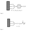
- Fig. 1 schematically shows the surface of an optical component which has been modified with silane compounds of formula (1) to form an anti-fog coating.
- the hydrophobic group -A1- is a phenylene and the terminal hydrophilic group is polyethoxy.
- the hydrophobic group -A1- is -poly (propoxylene) - and the terminal hydrophilic group is again polyethoxy.
- Fig. 2 again schematically shows the surface of an optical component which has been modified with silane compounds of formula (1) to form an antifogging coating.
- the hydrophobic group -A1- is a perfluorinated - poly (propoxylene) - and the terminal hydrophilic group is polyethoxy.
- the hydrophobic group -A1- is a perfluorinated alkylene- and the terminal hydrophilic group is again polyethoxy.
- Fig. 3 again schematically shows the surface of an optical component which has been modified with silane compounds of formula (1) to form an antifogging coating.
- the hydrophobic group -A1-a -phenylene and the terminal hydrophilic group is a sulfonic acid or a sulfonic acid ester.
- the optical component can be, for example, optical glass made of glass or plastic or else a beam splitter component.
- optical glass made of glass or plastic
- a beam splitter component By way of example, eyeglass lenses, binoculars, cover disks or cover glasses or else lenses such as eyepiece lenses, camera lenses or front lenses may be mentioned in this context.
- the optical component has an antireflection layer (AR layer).
- AR layer antireflection layer
- the antifogging coating may be applied directly to the AR layer.
- the layer thickness of the antifogging coating can be varied over a wide range, e.g. from a monomolecular (ie monolayer) layer to a multilayer layer with a layer thickness of up to 150 nm. If the optical component has an anti-reflection (AR) layer, the layer thickness of the anti-fog coating is preferably chosen such that the function of AR Layer is not affected. If the antifogging coating is present on an AR layer, the layer thickness of the antifogging coating is preferably in the range from single layer to 100 nm, more preferably in the range from 10 nm to 20 nm.
- AR anti-reflection
- Silane derivatives of the formula (1) are commercially available or can be prepared by synthesis methods known to those skilled in the art.
- silane derivatives are contacted in a suitable solvent with the surface under reactive conditions.
- the silane derivative can also be reacted with the surface via the gas phase.
- the present invention relates to a process for producing an antifogging coating on an optical component, comprising providing the optical component and the covalent attachment of the silane derivative of the formula (1) by chemical reaction with reactive groups on the surface of the optical component.
- the present invention relates to the use of the silane derivative of formula (1) to provide an antifogging coating on an optical component.
- the covalent attachment of the compound of formula (2) to the surface of the optical component is carried out by at least one of the reactive, hydrolyzable - Si-X groups with a suitable reactive surface group (eg a -OH Group) to form -Si-O- reacted.
- a suitable reactive surface group eg a -OH Group
- This type of surface connection of a silicon compound which has a reactive, hydrolyzable group is known in principle to the person skilled in the art.
- X is preferably methoxy, ethoxy or Cl.
- the crosslinked antifogue according to the invention significantly reduces the undesired adsorption of the hydrophilic group -B2 on the surface of the optical component, which in turn leads to an increased coverage of the molecules of the antifogging layer on the surface of the optical component.
- the terminal hydrophilic group -B2 is selected from polyethoxy, poly (meth) acrylate, sulfonic acid or a salt thereof, sulfonic acid ester, or a combination of these groups,
- the degree of ethoxylation of the polyethoxy group can be varied over a wide range and is for example in the range of 4 to 20.
- hydrophilic group -B2 contains a poly (meth) acrylate
- the poly (meth) acrylate as the hydrophilic group B2 may be linked, for example, via an ester group with the spacer group -B1 or the Si atom.
- the sulfonic acid ester is the methyl or ethyl ester.
- the spacer group if present, can be varied widely.
- a spacer group for example, an alkylene group such as C 1-8 alkylene, more preferably C 1-3 alkylene in question.
- Silane derivatives of the formula (2) are commercially available or can be prepared by synthesis methods known to those skilled in the art.
- silane derivatives are contacted in a suitable solvent with the surface under reactive conditions.
- the silane derivative can also be reacted with the surface via the gas phase.
- the present invention relates to a process for producing a crosslinked antifogging coating on an optical component comprising providing the optical component and covalently attaching the silane derivative of formula (2) by chemical reaction with reactive groups on the surface of the optical component, followed by cross-linking of the hydrophilic groups -B2 of adjacent molecules of the antifogging coating.
- Suitable reaction conditions for the cross-linking of adjacent molecules with suitable reactive groups are known to those skilled in the art. If the crosslinking takes place via a free-radical reaction, radical initiators, such as e.g. Dichlorodicyanoquinone (DDQ) can be used. Crosslinking can also be initiated under certain conditions by exposure to UV radiation.
- radical initiators such as e.g. Dichlorodicyanoquinone (DDQ) can be used.
- Crosslinking can also be initiated under certain conditions by exposure to UV radiation.
- the present invention relates to the use of the silane derivative of formula (2) to provide an antifogging coating on an optical component.
- the cross-linked anti-fog coating on the optical component by first covalently bonding a suitable precursor compound for the silane derivative of the formula (2) on the surface of the optical component, this precursor compound having a having terminal group with suitable functionality and thereby enables a subsequent chemical reaction with suitable reactants to the silane derivative of the formula (2).
- HEMA hydroxyethylene methacrylate
- AMPS 2-acrylamido-2-methylpropanesulfonic acid
- FIG. 4 schematically shows a surface of an optical component, which has been covered with a precursor compound (3).
- the terminal group of the precursor compound has a (meth) acrylate functionality which allows the reaction with further (meth) acrylate monomers and thus the construction of a hydrophilic poly (meth) acrylate group.
- a PEG-modified trichlorosilane (Mn ⁇ 500g / mol) is dissolved in toluene to give a 5 mass% solution.
- a glass with anti-reflective coating without CleanCoat is dipped in the solution for 30 minutes and then dried in air. The overcoat is rubbed off with a dry cloth.
- a PEG-modified trichlorosilane (Mn ⁇ 500g / mol) is dissolved in toluene to give a 2.5 mass% solution.
- a glass with anti-reflection coating without CleanCoat is dipped in the solution for 60 minutes and then dried in air. The overcoat is rubbed off with a dry cloth.
- Example 1 Both the coating obtained in Example 1 and in Example 2 by covalent attachment of the PEG-modified silane to the substrate surface exhibits an antifogging effect. Due to the higher concentration of the PEG-modified silane, the antifogging effect in Example 1 is more pronounced.
- Examples 3 and 4 first a precursor compound having a methacrylate functionality is covalently anchored to the substrate surface. Subsequently, the reaction is carried out with further (meth) acrylate monomers to form terminal poly (meth) acrylate groups, and cross-linking of adjacent molecules.
- a high proportion of the monomer hydroxyethyl methacrylate increases the hydrophilic character of the coating and thus also the antifogging effect, while a high proportion of the monomer trimethylolpropane triacrylate increases the crosslinking in the coating and thereby improves mechanical properties.
- the present invention relates to the following embodiments ⁇ 01 ⁇ - ⁇ 10 ⁇ :
- Embodiment ⁇ 02 ⁇ relates to the optical component according to embodiment ⁇ 01 ⁇ , wherein the antifogging coating does not have cross-linking between hydrophilic groups -A2 and / or hydrophobic groups -A1- of adjacent molecules.
- Embodiment ⁇ 03 ⁇ relates to the optical component according to embodiment ⁇ 01 ⁇ , wherein the antifogging coating has cross-linking between hydrophilic groups -A2 and / or hydrophobic groups -A1- of adjacent molecules.
- Embodiment ⁇ 05 ⁇ relates to the optical component according to one of the preceding embodiments ⁇ 01 ⁇ - ⁇ 04 ⁇ , wherein the covalent attachment of the compound of formula (1) or the compound of formula (2) to the surface of the optical component takes place by at least one of reactive -Si-X groups with a suitable reactive surface group to form -Si-O- reacted.
- Embodiment ⁇ 07 ⁇ relates to the optical component according to any one of the above embodiments ⁇ 01 ⁇ - ⁇ 05 ⁇ , wherein the optical component comprises a Antireflection coating and the antifogging coating is applied to the antireflection coating, wherein the antifogging coating preferably has a layer thickness of 100 nm or less.
- Embodiment ⁇ 08 ⁇ relates to a process for producing an antifogging coating on an optical component, comprising providing the optical component and covalently attaching the silane derivative of formula (1) according to embodiment ⁇ 01 ⁇ by chemical reaction with reactive groups on the surface of the optical component.
- Embodiment ⁇ 09 ⁇ relates to a method for producing a crosslinked antifogging coating on an optical component, comprising providing the optic component and covalently attaching the silane derivative of formula (2) according to embodiment ⁇ 04 ⁇ by chemical reaction with reactive groups on the surface of the optical component followed by cross-linking of the hydrophilic groups -B2 of adjacent molecules of the antifogging coating.
Landscapes
- Chemical & Material Sciences (AREA)
- Physics & Mathematics (AREA)
- Engineering & Computer Science (AREA)
- Life Sciences & Earth Sciences (AREA)
- Materials Engineering (AREA)
- Organic Chemistry (AREA)
- Chemical Kinetics & Catalysis (AREA)
- Optics & Photonics (AREA)
- General Physics & Mathematics (AREA)
- Wood Science & Technology (AREA)
- General Chemical & Material Sciences (AREA)
- Geochemistry & Mineralogy (AREA)
- Paints Or Removers (AREA)
- Surface Treatment Of Optical Elements (AREA)
Abstract
Description
- Die vorliegende Erfindung betrifft eine Antifog-Beschichtung auf einer Optikkomponente sowie ein Verfahren zu deren Herstellung.
- Heutige Brillengläser (Korrektionsbrillen, Sonnenbrillen, Ski/Sport Brillen, Schutzbrillen) beschlagen unter ungünstigen Bedingungen. Diese Bedingungen sind zum einen der Übergang von einer kalten Umgebung in eine warme Umgebung (z.B. man kommt im Winter bei kalten Temperaturen von draußen in die Wohnung, oder man verlässt in einem Land mit tropischen Klimabedingungen ein klimatisiertes Gebäude), zum anderen wenn das Brillenglas mit einer Quelle warmer/heisser Luft mit hoher relativer Luftfeuchtigkeit in Kontakt kommt. Typischerweise muss der Brillenträger nach dem Beschlagen seine Brille abnehmen und warten bis der Beschlag verschwindet oder er muss den Beschlag mit einem Tuch abwischen.
- Das Problem des Beschlagens betrifft allgemein Optikkomponenten.
- Untersucht man den Beschlag mit einem Lichtmikroskop, stellt man fest, dass der Beschlag aus kleinen Wassertröpfchen besteht. Diese haben einen Durchmesser von typischerweise 20µm. Der Oberflächenbelegungsgrad dieser Tröpfchen ist in etwa 50%, was auch kinetische theoretische Modelle vorhersagen. Dass ein beschlagenes Brillenglas milchig erscheint, liegt daran, dass die Lichtausbreitung durch die Tröpfchen gestört wird.
- Mit der Reduzierung der Transmission geht gleichzeitig eine Erhöhung des Streulichtanteils einher, die das Glas milchig erscheinen lassen. Ein niedriger Kontaktwinkel der Wassertröpfchen vorteilhaft, die Transmission ist dann hoch und der Streulichtanteil niedrig.
- Da sich die Kondensation von Wasser unter den Bedingungen, bei denen Brillengläser beschlagen, nicht verhindern lässt, ist ein Lösungsansatz, die Oberfläche so zu behandeln, dass die Wassertropfen einen kleinen Kontaktwinkel mit der Oberfläche ausbilden.
- Es gibt Ansätze, wie dies für optische Gläser wie z.B. Brillengläser umgesetzt werden kann. Typsicherweise sind dies Sprays oder mit Flüssigkeiten getränkte Tücher. Die zum Einsatz kommenden Flüssigkeiten sind dabei aus der Gruppe der hydrophilen Tenside. Es gibt eine Vielzahl solcher Produkte am Markt. Diesen Produkten ist gemeinsam, dass der Anti-Beschlag-Effekt bzw. Antifog-Effekt nicht dauerhaft ist, sonder die Lösung regelmäßig auf die Oberfläche aufgetragen werden muss. Ebenso gibt es Ansätze, die mit Hilfe physikalischer Effekte die Ausbildung von Wassertropfen verhindern, beispielsweise Belüftungssysteme in Skibrillen.
- Des Weiteren gibt es Lösungen für optische Gläser wie Brillengläser, die mit einer Hart-Beschichtung versehen sind und die einen dauerhaften anti-Beschlag-Effekt (Antifog-Effekt) gewährleisten.
- Heutige hochwertige optische Gläser wie z.B. hochwertige Brillengläser sind im Regelfall mit einer anti-Reflex (AR) Beschichtung versehen. Diese reduziert ungewünschte, irritierende Reflexe.
- Es ist vorteilhaft, wenn es gelingt, die Oberfläche von mit AR-Schichten versehenen Optikkomponenten wie z.B. Brillengläsern so zu modifizieren, dass ein dauerhafter anti-Beschlag-Effekt bzw. Antifog-Effekt erzielt wird, so dass eine regelmäßige Nachbehandlung, z.B. mit einem Spray, entfällt. Ein besonderes Augenmerk ist dabei darauf zu legen, dass die optische Wirkung der anti-Reflexionsschicht erhalten bleibt.
- Gemäß eines ersten Aspekts wird diese Aufgabe gelöst durch die Bereitstellung einer Optikkomponente mit einer Antifog- oder Antibeschlag-Beschichtung, erhältlich durch kovalente Anbindung eines Silanderivats der Formel (1) an die Oberfläche der Optikkomponente:
RoXmSiAn (1)
wobei
m=1-3, n=1-2 und o=0-1, unter der Voraussetzung, dass m+n+o=4;
der Rest X ausgewählt wird aus Halogen oder C1-4-Alkoxy, wobei für m=2-3 die einzelnen Reste X gleich oder unterschiedlich sein können,
der Rest R C1-4Alkyl ist,
der Rest A die Struktur -A1-A2 aufweist, in der -A1- eine hydrophobe Gruppe, die an das Si-Atom gebunden ist, und A2 eine an die hydrophobe Gruppe A1 gebundene, endständige hydrophile Gruppe darstellen,
wobei die hydrophobe Gruppe -A1- ausgewählt wird aus -Arylen-; -Alkylen-; -C1-6Alkylen-Arylen-; -Arylen-C1-6Alkylen-; -C1-6Alkylen-Arylen-C1-6Alkylen-; -Poly(C3-6Alkoxylen)-, fluoriertem oder perfluoriertem -Alkylen-, fluoriertem oder perfluoriertem -Poly(C2-6Alkoxylen)-, oder einer Kombination dieser Gruppen, und die endständige hydrophile Gruppe -A2 ausgewählt wird aus Polyethoxyl, Poly(meth)acrylat, Sulfonsäure oder einem Salz davon, Sulfonsäureester, oder einer Kombination dieser Gruppen, wobei für n=2 die einzelnen Reste A gleich oder unterschiedlich sein können. - Die kovalente Anbindung der Verbindung der Formel (1) an die Oberfläche der Optikkomponente erfolgt, indem mindestens eine der reaktiven, hydrolysierbaren - Si-X-Gruppen mit einer geeigneten reaktiven Oberflächengruppe (z.B. einer -OH Gruppe) unter Ausbildung von -Si-O- reagiert. Diese Art der Oberflächenanbindung einer Siliziumverbindung, die eine reaktive, hydrolysierbare Gruppe aufweist, ist dem Fachmann grundsätzlich bekannt.
- Bevorzugt handelt es sich bei X um Methoxy, Ethoxy oder Cl.
- Im Rahmen der vorliegenden Erfindung wurde festgestellt, dass durch einen Rest A am Si-Atom mit der Struktur -A1-A2, welcher eine geeignete Kombination aus hydrophober Gruppe -A1- und endständiger hydrophiler Gruppe -A2 aufweist, einerseits die -Si-O-Bindung, über die die Moleküle der Antifog-Beschichtung an die Oberfläche der Optikkomponente gebunden sind, besser vor Wasser abgeschirmt wird und die Hydrolysestabilität der Antifog-Beschichtung erhöht werden kann und außerdem der Kontaktwinkel des Wassers zur Antifog-Beschichtung gering gehalten wird.
- Im Rahmen der vorliegenden Erfindung hat sich auch gezeigt, dass die Anwesenheit einer geeigneten hydrophoben Gruppe -A1- in der Verbindung der Formel (1) die unerwünschte Adsorption der hydrophilen Gruppe -A2 auf der Oberfläche der Optikkomponente deutlich reduziert, was wiederum zu einer erhöhten Belegungsdichte der Moleküle der Antifogschicht auf der Oberfläche der Optikkomponente führt.
- Wie oben dargelegt, wird die hydrophobe Gruppe -A1- ausgewählt aus -Arylen-; -C1-6Alkylen-Arylen-, -Arylen-C1-6Alkylen-, -C1-6Alkylen-Arylen-C1-6Alkylen-; -Poly(C3-6Alkoxylen)-, fluoriertem oder perfluoriertem -Alkylen-, fluoriertem oder perfluoriertem -Poly(C3-6Alkoxylen)-, oder einer Kombination dieser Gruppen,
- Aus der Struktur -A1-A2 des Restes A ergibt sich, dass die hydrophobe Gruppe zumindest bivalent ist, also mit jeweils einer kovalente Bindung mit den beiden benachbarten Gruppen verbunden ist. Im Folgenden trägt die Bezeichnung einer solchen bivalenten Gruppe die Endung "-en". Beispielsweise wird mit dem Begriff "Arylen" nachfolgend eine bivalente Aryl-Gruppe bezeichnet.
- Bevorzugt handelt es sich bei der Arylen-Gruppe -Ar- um Phenylen -Ph-, das substituiert oder unsubstituiert sein kann. Gegebenenfalls kann die Arylen-Gruppe über eine (bivalente) C1-6Alkylen-Gruppe, die optional fluoriert oder perfluoriert ist, mit dem Si-Atom und/oder der endständigen hydrophilen Gruppe A2 verbunden sein.
- Eine geeignete Alkylen-Gruppe ist z.B. -C1-10Alkylen-.
- Bei -Poly(C3-6-Alkoxylen)- handelt es sich bevorzugt um eine Polypropoxylen-und/oder Polybutoxylen-Gruppe. Im Rahmen der vorliegenden Erfindung hat sich gezeigt, dass -Poly(C3-6-Alkoxylen)- eine ausreichende Hydrophobizität aufweist, um die Hydrolysestabilität der Antifog-Beschichtung zu verbessern. Der Alkoxylierungsgrad, d.h. die Anzahl der C3-6-Alkoxylen-Monomereinheiten in der Poly(C3-6-Alkoxylen)-Gruppe kann über einen breiten Bereich variiert werden und liegt beispielsweise im Bereich von 1 bis 8, bevorzugter 2 bis 8.
- Im Rahmen der vorliegenden Erfindung wird unter einer perfluorierten Alkylen-Gruppe eine Alkylen-Gruppe verstanden, bei der sämtliche Wasserstoffatome durch Fluor substituiert sind. Die Anzahl der C-Atome der fluorierten oder perfluorierten Alkylen-Gruppe und damit deren Länge kann über einen breiten Bereich variiert werden. Bevorzugt handelt es sich bei der fluorierten oder perfluorierten Alkylen-Gruppe um eine fluorierte oder perfluorierte C1-20-Alkylengruppe, bevorzugter fluorierte oder perfluorierte C1-10-Alkylen.
- Im Rahmen der vorliegenden Erfindung wird unter einer perfluorierten Poly(C2-6-Alkoxylen)-Gruppe eine Poly(C2-6-Alkoxylen)-Gruppe verstanden, bei der sämtliche Wasserstoffatome durch Fluor substituiert sind. Als beispielhafte Poly(C2-6-Alkoxylen)-Gruppen können Polyethoxylen, Polypropoxylen oder Polybutoxylen genannt werden. Der Alkoxylierungsgrad, d.h. die Anzahl der C2-6-Alkoxylen-Monomereinheiten in der fluorierten oder perfluorierten Poly(C2-6-Alkoxylen)-Gruppe kann über einen breiten Bereich variiert werden und liegt beispielsweise im Bereich von 1 bis 8, bevorzugter 2 bis8.
- Wie oben ausgeführt, wird die endständige hydrophile Gruppe -A2 ausgewählt aus Polyethoxyl, Poly(meth)acrylat, Sulfonsäure oder einem Salz davon, Sulfonsäureester, oder einer Kombination dieser Gruppen
- Der Ethoxylierungsgrad der Polyethoxygruppe kann über einen breiten Bereich variiert werden und liegt beispielsweise im Bereich von 4 bis 20.
- Bevorzugt handelt es sich bei dem Sulfonsäureester um den Methyl- oder Ethylester.
- Enthält die hydrophile Gruppe -A2 ein Poly(meth)acrylat, so kann dieses ausschließlich aus identischen Monomereinheiten wie CH2=C(CH3)COOC1-4-Alkyl (z.B. CH2=C(CH3)COOCH3), CH2=C(H)COOC1-4-Alkyl (z.B. CH2=C(H)COOCH3), Hydroxyethylenmethacrylat (HEMA), 2-Acrylamido-2-methylpropansulfonsäure (AMPS), Trimethylolpropantriacrylat oder Pentaerythritoltetraacrylat oder aus Gemischen dieser Monomereinheiten aufgebaut sein und kann alternativ noch weitere Comonomereinheiten enthalten. Das Poly(meth)acrylat als hydrophile Gruppe A2 kann beispielsweise über eine Estergruppe mit der hydrophoben Gruppe -A1- verknüpft sein.
- Im Rahmen der vorliegenden Erfindung ist es möglich, dass benachbarte Moleküle der Formel (1) der Antifog-Beschichtung über kovalente Bindungen der hydrophilen Gruppen -A2 quervernetzt sind, insbesondere wenn -A2 Polyethoxyl oder Poly(meth)acrylat ist. Dies kann zu einer noch besseren Abschirmung der -Si-O-Bindung gegenüber Wasser führen. Sofern allerdings die Verbindung die oben beschriebene Struktur mit -A1-A2 aufweist, führt dies auch ohne Quervernetzung zu einer verbesserten Hydrolysestabilität.
-
Fig. 1 zeigt schematisch die Oberfläche einer Optikkomponente, die mit Silanverbindungen der Formel (1) unter Ausbildung einer Antifog-Beschichtung modifiziert wurde. In der oberen Verbindung derFigur 1 ist die hydrophobe Gruppe -A1- ein -Phenylen- und die endständige hydrophile Gruppe ist Polyethoxy. In der unteren Verbindung derFigur 1 ist die hydrophobe Gruppe -A1- ein -Poly(propoxylen)- und die endständige hydrophile Gruppe ist wiederum Polyethoxy. -
Fig. 2 zeigt wiederum schematisch die Oberfläche einer Optikkomponente, die mit Silanverbindungen der Formel (1) unter Ausbildung einer Antifog-Beschichtung modifiziert wurde. In der oberen Verbindung derFigur 2 ist die hydrophobe Gruppe -A1- ein perfluoriertes - Poly(propoxylen)- und die endständige hydrophile Gruppe ist Polyethoxy. In der unteren Verbindung derFigur 1 ist die hydrophobe Gruppe -A1- ein perfluoriertes -Alkylen- und die endständige hydrophile Gruppe ist wiederum Polyethoxy. -
Fig. 3 zeigt wiederum schematisch die Oberfläche einer Optikkomponente, die mit Silanverbindungen der Formel (1) unter Ausbildung einer Antifog-Beschichtung modifiziert wurde. In der Verbindung derFigur 3 ist die hydrophobe Gruppe -A1-ein -Phenylen- und die endständige hydrophile Gruppe ist eine Sulfonsäure oder ein Sulfonsäureester. - Bei der Optikkomponente kann es sich z.B. um optische Gläser aus Glas oder Kunststoff oder auch um eine Strahlteilerkomponente handeln. Beispielhaft können in diesem Zusammenhang Brillengläser, Ferngläser, Abdeckscheiben bzw. Abdeckgläser oder auch Linsen wie Okkularlinsen, Kameralinsen oder Frontlinsen genannt werden.
- In einer bevorzugten Ausführungsform weist die Optikkomponente eine Antireflektionsschicht (AR-Schicht) auf. Die Antifog-Beschichtung kann direkt auf der AR-Schicht angebracht sein.
- Die Schichtdicke der Antifog-Beschichtung kann über einen breiten Bereich variiert werden, z.B. von einer monomolekularen (d.h. einlagigen) Schicht bis zu einer mehrlagigen Schicht mit einer Schichtdicke von bis zu 150 nm. Sofern die Optikkomponente eine Antireflektionsschicht (AR-Schicht) aufweist, wird die Schichtdicke der Antifog-Beschichtung bevorzugt so gewählt, dass die Funktion der AR-Schicht nicht beeinträchtigt wird. Liegt die Antifog-Beschichtung auf einer AR-Schicht vor, so liegt die Schichtdicke der Antifog-Beschichtung bevorzugt im Bereich von einlagig bis 100 nm, bevorzugter im Bereich von 10 nm bis 20 nm.
- Silanderivate der Formel (1) sind kommerziell erhältlich oder können über dem Fachmann bekannte Syntheseverfahren hergestellt werden.
- Verfahren zur kovalenten Anbindung von Silanderivaten auf reaktiven Oberflächen sind dem Fachmann grundsätzlich bekannt. Gemäß einer Variante wird das Silanderivat in einem geeigneten Lösungsmittel mit der Oberfläche unter reaktiven Bedingungen in Kontakt gebracht. Alternativ kann das Silanderivat auch über die Gasphase mit der Oberfläche zur Reaktion gebracht werden.
- Gemäß eines weiteren Aspekts betrifft die vorliegende Erfindung ein Verfahren zur Herstellung einer Antifog-Beschichtung auf einer Optikkomponente, umfassend die Bereitstellung der Optikkomponente und die kovalente Anbindung des Silanderivats der Formel (1) durch chemische Reaktion mit reaktiven Gruppen auf der Oberfläche der Optikkomponente.
- Bezüglich der Eigenschaften des Silanderivats der Formel (1) und der Optikkomponente kann auf die obigen Ausführungen verwiesen werden.
- Gemäß eines weiteren Aspekts betrifft die vorliegende Erfindung die Verwendung des Silanderivats der Formel (1) zur Bereitstellung einer Antifog-Beschichtung auf einer Optikkomponente.
- Gemäß eines weiteren Aspekts betrifft die vorliegende Erfindung eine Optikkomponente mit einer quervernetzten Antifog-Beschichtung, erhältlich durch kovalente Anbindung eines Silanderivats der Formel (2) an die Oberfläche der Optikkomponente und Quervernetzung benachbarter Moleküle:
RoXmSiBn (2)
wobei
m=1-3, n=1-2 und o=0-1, unter der Voraussetzung, dass m+n+o=4,
der Rest X ausgewählt wird aus Halogen oder C1-4-Alkoxy, wobei für m=2-3 die einzelnen Reste X gleich oder unterschiedlich sein können,
der Rest R C1-4Alkyl ist,
der Rest B die Struktur -B1-B2 aufweist, in der B2 eine endständige hydrophile Gruppe ist, die mit mindestens einer hydrophilen Gruppe eines benachbarten Moleküls der Antifog-Schicht quervernetzt ist, und -B1- entweder eine Spacer-Gruppe, die die hydrophile Gruppe B2 mit dem Si-Atom verbindet, oder eine kovalente Bindung darstellt,
wobei die endständige hydrophile Gruppe -B2 ausgewählt wird aus Polyethoxy, Poly(meth)acrylat, Sulfonsäure oder einem Salz davon, Sulfonsäureester, oder einer Kombination dieser Gruppen,
wobei für n=2 die einzelnen Reste B gleich oder unterschiedlich sein können. - Die kovalente Anbindung der Verbindung der Formel (2) an die Oberfläche der Optikkomponente erfolgt, indem mindestens eine der reaktiven, hydrolysierbaren - Si-X-Gruppen mit einer geeigneten reaktiven Oberflächengruppe (z.B. einer -OH Gruppe) unter Ausbildung von -Si-O- reagiert. Diese Art der Oberflächenanbindung einer Siliziumverbindung, die eine reaktive, hydrolysierbare Gruppe aufweist, ist dem Fachmann grundsätzlich bekannt.
- Bevorzugt handelt es sich bei X um Methoxy, Ethoxy oder Cl.
- Im Rahmen der vorliegenden Erfindung wurde festgestellt, dass durch die Auswahl geeigneter hydrophiler Gruppen in dem Silanderivat der Formel (2) und der Vernetzung benachbarter Moleküle in der Antifog-Beschichtung einerseits die -Si-O-Bindung, über die die Moleküle der Antifog-Beschichtung an die Oberfläche der Optikkomponente gebunden sind, besser vor Wasser abgeschirmt wird und die Hydrolysestabilität der Antifog-Beschichtung erhöht werden kann und außerdem der Kontaktwinkel des Wassers zur Antifog-Beschichtung gering gehalten wird.
- Im Rahmen der vorliegenden Erfindung hat sich auch gezeigt, dass die erfindungsgemäße quervernetzte Antifog die unerwünschte Adsorption der hydrophilen Gruppe -B2 auf der Oberfläche der Optikkomponente deutlich reduziert, was wiederum zu einer erhöhten Belegungsdichte der Moleküle der Antifogschicht auf der Oberfläche der Optikkomponente führt.
- Wie oben ausgeführt, wird die endständige hydrophile Gruppe -B2 ausgewählt aus Polyethoxy, Poly(meth)acrylat, Sulfonsäure oder einem Salz davon, Sulfonsäureester, oder einer Kombination dieser Gruppen,
- Hinsichtlich der Eigenschaften dieser hydrophilen Gruppen kann auf die obigen Ausführungen bei der Beschreibung des Silanderivats (1) verwiesen werden.
- Der Ethoxylierungsgrad der Polyethoxygruppe kann über einen breiten Bereich variiert werden und liegt beispielsweise im Bereich von 4 bis 20.
- Enthält die hydrophile Gruppe -B2 ein Poly(meth)acrylat, so kann dieses ausschließlich aus identischen Monomereinheiten wie CH2=C(CH3)COOC1-4-Alkyl (z.B. CH2=C(CH3)COOCH3), CH2=C(H)COOC1-4-Alkyl (z.B. CH2=C(H)COOCH3), Hydroxyethylenmethacrylat (HEMA), 2-Acrylamido-2-methylpropansulfonsäure (AMPS), Trimethylolpropantriacrylat oder Pentaerythritoltetraacrylat oder aus einem Gemisch dieser Monomereinheiten aufgebaut sein und kann optional noch weitere zusätzliche Comonomereinheiten enthalten. Das Poly(meth)acrylat als hydrophile Gruppe B2 kann beispielsweise über eine Estergruppe mit der Spacer-Gruppe -B1-oder dem Si-Atom verknüpft sein.
- Bevorzugt handelt es sich bei dem Sulfonsäureester um den Methyl- oder Ethylester.
- Im Rahmen der vorliegenden Erfindung kann die Spacer-Gruppe, sofern sie vorliegt, in breitem Umfang variiert werden. Als Spacer-Gruppe kommt beispielsweise eine Alkylen-Gruppe wie C1-8Alkylen, bevorzugter C1-3Alkylen in Frage.
- Silanderivate der Formel (2) sind kommerziell erhältlich oder können über dem Fachmann bekannte Syntheseverfahren hergestellt werden.
- Verfahren zur kovalenten Anbindung von Silanderivaten auf reaktiven Oberflächen sind dem Fachmann grundsätzlich bekannt. Gemäß einer Variante wird das Silanderivat in einem geeigneten Lösungsmittel mit der Oberfläche unter reaktiven Bedingungen in Kontakt gebracht. Alternativ kann das Silanderivat auch über die Gasphase mit der Oberfläche zur Reaktion gebracht werden.
- Gemäß eines weiteren Aspekts betrifft die vorliegende Erfindung ein Verfahren zur Herstellung einer quervernetzten Antifog-Beschichtung auf einer Optikkomponente, umfassend die Bereitstellung der Optikkomponente und die kovalente Anbindung des Silanderivats der Formel (2) durch chemische Reaktion mit reaktiven Gruppen auf der Oberfläche der Optikkomponente, gefolgt von der Quervernetzung der hydrophilen Gruppen -B2 benachbarter Moleküle der Antifog-Beschichtung.
- Geeignete Reaktionsbedingungen für die Quervernetzung benachbarter Moleküle mit geeigneten reaktiven Gruppen sind dem Fachmann bekannt. Erfolgt die Quervernetzung über eine radikalische Reaktion, können Radikalstarter wie z.B. Dichlordicyanochinon (DDQ) eingesetzt werden. Eine Quervernetzung kann bei bestimmten Gruppen auch unter Einwirkung von UV-Strahlung initiiert werden.
- Bezüglich der Eigenschaften des Silanderivats der Formel (2) und der Optikkomponente kann auf die obigen Ausführungen verwiesen werden.
- Gemäß eines weiteren Aspekts betrifft die vorliegende Erfindung die Verwendung des Silanderivats der Formel (2) zur Bereitstellung einer Antifog-Beschichtung auf einer Optikkomponente.
- Im Rahmen der vorliegenden Erfindung ist es auch möglich, die quervernetzte Antifog-Beschichtung auf der Optikkomponente herzustellen, indem zunächst eine geeignete Precursor-Verbindung für das Silanderivat der Formel (2) auf der Oberfläche der Optikkomponente kovalent gebunden wird, wobei diese Precursor-Verbindung eine endständige Gruppe mit geeigneter Funktionalität aufweist und dadurch eine anschließende chemische Umsetzung mit geeigneten Reaktionspartnern zu dem Silanderivat der Formel (2) ermöglicht.
- Gemäß eines weiteren Aspekts betrifft die vorliegende Erfindung daher ein Verfahren zur Herstellung einer quervernetzten Antifog-Beschichtung auf einer Optikkomponente, wobei zunächst eine Precursorverbindung der Formel (3) kovalent auf die Oberfläche der Optikkomponente gebunden wird:
RoXmSiCn (3)
wobei
m=1-3, n=1-2 und o=0-1, unter der Voraussetzung, dass m+n+o=4,
der Rest X ausgewählt wird aus Halogen oder C1-4-Alkoxy, wobei für m=2-3 die einzelnen Reste X gleich oder unterschiedlich sein können,
der Rest R C1-4Alkyl ist,
der Rest C die Struktur -C1-C2 aufweist, in der -C2 eine endständige Gruppe mit einer (Meth)acrylat-Funktionalität ist und -C1- entweder eine Spacer-Gruppe, die der oben beschriebenen Spacer-Gruppe -B1- entspricht, oder eine kovalente Bindung darstellt,
und die endständige Gruppe C2 mit (Meth)acrylat-Monomeren zu einer hydrophilen Poly(meth)acrylat-Gruppe umgesetzt wird, gefolgt von der Quervernetzung der hydrophilen Poly(meth)acrylat-Gruppen benachbarter Moleküle der Antifog-Beschichtung. - Als geeignete (Meth)acrylat-Monomere können beispielsweise CH2=C(CH3)COOC1-4-Alkyl (z.B. CH2=C(CH3)COOCH3), CH2=C(H)COOC1-4-Alkyl (z.B. CH2=C(H)COOCH3), Hydroxyethylenmethacrylat (HEMA), 2-Acrylamido-2-methylpropansulfonsäure (AMPS), Trimethylolpropantriacrylat oder Pentaerythritoltetraacrylat oder deren Gemische genannt werden.
-
Figur 4 zeigt schematisch eine Oberfläche einer Optikkomponente, die mit einer Precursor-Verbindung (3) belegt wurde. Die endständige Gruppe der Precursor-Verbindung weist eine (Meth)Acrylat-Funktionalität auf, die die Umsetzung mit weiteren (Meth)Acrylat-Monomeren und somit den Aufbau einer hydrophilen Poly(meth)acrylat-Gruppe ermöglicht. - Die Erfindung wird durch die nachfolgenden Beispiele eingehender beschrieben.
- Ein PEG-modifiziertes Trichlorosilan (Mn∼500g/mol) wird in Toluol gelöst, so dass eine 5Massen% Lösung entsteht. Ein Glas mit Antireflexbeschichtung ohne CleanCoat wird 30 Minuten in die Lösung getaucht und danach an der Luft getrocknet. Die Überbeschichtung wird mit einem trockenen Tuch abgerieben.
- Ein PEG-modifiziertes Trichlorosilan (Mn∼500g/mol) wird in Toluol gelöst, so dass eine 2,5Massen% Lösung entsteht. Ein Glas mit Antireflexbeschichtung ohne CleanCoat wird 60 Minuten in die Lösung getaucht und danach an der Luft getrocknet. Die Überbeschichtung wird mit einem trockenen Tuch abgerieben.
- Sowohl die in Beispiel 1 als auch die in Beispiel 2 durch kovalente Anbindung des PEG-modifizierten Silans an die Substratoberfläche erhaltene Beschichtung zeigt eine Antifog-Wirkung. Aufgrund der höheren Konzentration des PEG-modifizierten Silans ist der Antifog-Effekt in Beispiel 1 ausgeprägter.
- In 490mL Toluol werden 9,98g 3-Methacryloxypropyl(trichlorsilan) gelöst. Ein Glas wird in dieser Lösung eine Stunde gelagert und dann an der Luft getrocknet. Im zweiten Schritt wird das gleiche Glas kurz in eine Lösung bestehend aus 5,0g 2-Hydroxyethylmethacrylat (HEMA), 1,0g Trimethylolpropantriacrylat (TMPTA) und 0,5g Diphenyl-(2,4,6-trimethylbenzoyl)phosphinoxid in 50mL Toluol getaucht und danach mit einer Panacol UV-D-1000-Lampe ausgehärtet.
- 10,01g 3-Methacryloxypropyl(trichlorsilan) werden in 240mL Toluol gelöst und ein Glas mit Antireflexbeschichtung wird eine Stunde darin gelagert und danach an der Luft getrocknet. Im zweiten Schritt wird das gleiche Glas in eine Lösung bestehend aus 10,0g HEMA, 3,0g TMPTA und 0,5g Diphenyl-(2,4,6-trimethylbenzoyl)phosphin-oxid in 100mL Toluol getaucht und danach mit einer Panacol UV-D-1000-Lampe ausgehärtet.
- In den Beispielen 3 und 4 wird zunächst eine Precursor-Verbindung mit einer Methacrylatfunktionalität kovalent auf der Substratoberfläche verankert. Anschließend erfolgt die Reaktion mit weiteren (Meth)acrylat-Monomeren, um endständige Poly(meth)acrylat-Gruppen auszubilden, und eine Quervernetzung benachbarter Moleküle.
- Sowohl die in Beispiel 3 als auch die in Beispiel 4 hergestellte Beschichtung zeigt eine Antifog-Wirkung.
- Ein hoher Anteil des Monomers Hydroxyethylmethacrylat erhöht den hydrophilen Charakter der Beschichtung und damit auch die Antifog-Wirkung, während ein hoher Anteil des Monomers Trimethylolpropantriacrylat die Vernetzung in der Beschichtung erhöht und dadurch mechanische Eigenschaften verbessert.
- Bevorzugt betrifft die vorliegende Erfindung die folgenden Ausführungsformen {01}-{10}:
- Ausführungsform {01} betrifft eine Optikkomponente mit einer Antifog-Beschichtung, erhältlich durch kovalente Anbindung eines Silanderivats der Formel (1) an die Oberfläche der Optikkomponente:
RoXmSiAn (1)
wobei
m=1-3, n=1-2 und o=0-1, unter der Voraussetzung, dass m+n+o=4;
der Rest X ausgewählt wird aus Halogen oder C1-4-Alkoxy, wobei für m=2-3 die einzelnen Reste X gleich oder unterschiedlich sein können,
der Rest R C1-4Alkyl ist,
der Rest A die Struktur -A1-A2 aufweist, in der -A1- eine hydrophobe Gruppe, die an das Si-Atom gebunden ist, und -A2 eine an die hydrophobe Gruppe A1 gebundene, endständige hydrophile Gruppe darstellen,
wobei die hydrophobe Gruppe -A1- ausgewählt wird aus -Arylen-; -C1-6Alkylen-Arylen-; -Arylen-C1-6Alkylen-; -C1-6Alkylen-Arylen-C1-6Alkylen-; -Poly(C3-6Alkoxylen)-, fluoriertem oder perfluoriertem -Alkylen-, fluoriertem oder perfluoriertem -Poly(C2-6Alkoxylen)-, oder einer Kombination dieser Gruppen, und die endständige hydrophile Gruppe -A2 ausgewählt wird aus Polyethoxy, Poly(meth)acrylat, Sulfonsäure oder einem Salz davon, Sulfonsäureester, oder einer Kombination dieser Gruppen, wobei für n=2 die einzelnen Reste A gleich oder unterschiedlich sein können. - Ausführungsform {02} betrifft die Optikkomponente gemäß Ausführungsform {01}, wobei die Antifog-Beschichtung keine Quervernetzung zwischen hydrophilen Gruppen -A2 und/oder hydrophoben Gruppen -A1- benachbarter Moleküle aufweist.
- Ausführungsform {03} betrifft die Optikkomponente gemäß Ausführungsform {01}, wobei die Antifog-Beschichtung eine Quervernetzung zwischen hydrophilen Gruppen -A2 und/oder hydrophoben Gruppen -A1- benachbarter Moleküle aufweist.
- Ausführungsform {04} betrifft eine Optikkomponente mit einer quervernetzten Antifog-Beschichtung, erhältlich durch kovalente Anbindung eines Silanderivats der Formel (2) an die Oberfläche der Optikkomponente und Quervernetzung benachbarter Moleküle:
RoXmSiBn (2)
wobei
m=1-3, n=1-2 und o=0-1, unter der Voraussetzung, dass m+n+o=4,
der Rest X ausgewählt wird aus Halogen oder C1-4-Alkoxy, wobei für m=2-3 die einzelnen Reste X gleich oder unterschiedlich sein können,
der Rest R C1-4Alkyl ist,
der Rest B die Struktur -B1-B2 aufweist, in der B2 eine endständige hydrophile Gruppe ist, die mit mindestens einer hydrophilen Gruppe eines benachbarten Moleküls der Antifog-Schicht quervernetzt ist, und -B1-entweder eine Spacer-Gruppe, die die hydrophile Gruppe B2 mit dem Si-Atom verbindet, oder eine kovalente Bindung darstellt,
wobei die endständige hydrophile Gruppe -B2 ausgewählt wird aus Polyethoxy, Poly(meth)acrylat, Sulfonsäure oder einem Salz davon, Sulfonsäureester, oder einer Kombination dieser Gruppen,
wobei für n=2 die einzelnen Reste B gleich oder unterschiedlich sein können. - Ausführungsform {05} betrifft die Optikkomponente nach einer der vorstehenden Ausführungsformen {01}-{04}, wobei die kovalente Anbindung der Verbindung der Formel (1) oder der Verbindung der Formel (2) an die Oberfläche der Optikkomponente erfolgt, indem mindestens eine der reaktiven -Si-X-Gruppen mit einer geeigneten reaktiven Oberflächengruppe unter Ausbildung von -Si-O- reagiert.
- Ausführungsform {06} betrifft die Optikkomponente nach einer der vorstehenden Ausführungsformen {01}-{05}, wobei das Poly(meth)acrylat der endständigen hydrophilen Gruppe -A2 oder -B2 Monomereinheiten umfasst, die aus CH2=C(CH3)COOC1-4-Alkyl, CH2=C(H)COOC1-4-Alkyl, Hydroxyethylenmethacrylat, 2-Acrylamido-2-methylpropansulfonsäure, Trimethylolpropantriacrylat oder Pentaerythritoltetraacrylat oder deren Gemischen ausgewählt werden.
- Ausführungsform {07} betrifft die Optikkomponente nach einer der vorstehenden Ausführungsformen {01}-{05}, wobei die Optikkomponente eine Antireflektionsschicht umfasst und die Antifog-Beschichtung auf der Antireflektionsschicht aufgebracht ist, wobei die Antifog-Beschichtung bevorzugt eine Schichtdicke von 100 nm oder weniger aufweist.
- Ausführungsform {08} betrifft ein Verfahren zur Herstellung einer Antifog-Beschichtung auf einer Optikkomponente, umfassend die Bereitstellung der Optikkomponente und die kovalente Anbindung des Silanderivats der Formel (1) gemäß Ausführungsform {01} durch chemische Reaktion mit reaktiven Gruppen auf der Oberfläche der Optikkomponente.
- Ausführungsform {09} betrifft ein Verfahren zur Herstellung einer quervernetzten Antifog-Beschichtung auf einer Optikkomponente, umfassend die Bereitstellung der Optikkomponente und die kovalente Anbindung des Silanderivats der Formel (2) gemäß Ausführungsform {04} durch chemische Reaktion mit reaktiven Gruppen auf der Oberfläche der Optikkomponente, gefolgt von der Quervernetzung der hydrophilen Gruppen -B2 benachbarter Moleküle der Antifog-Beschichtung.
- Ausführungsform {10} betrifft ein Verfahren zur Herstellung einer quervernetzten Antifog-Beschichtung auf einer Optikkomponente, wobei zunächst eine Precursorverbindung der Formel (3) kovalent auf die Oberfläche der Optikkomponente gebunden wird:
RoXmSiCn (3)
wobei
m=1-3, n=1-2 und o=0-1, unter der Voraussetzung, dass m+n+o=4,
der Rest X ausgewählt wird aus Halogen oder C1-4-Alkoxy, wobei für m=2-3 die einzelnen Reste X gleich oder unterschiedlich sein können,
der Rest R C1-4Alkyl ist,
der Rest C die Struktur -C1-C2 aufweist, in der -C2 eine endständige Gruppe mit einer (Meth)acrylat-Funktionalität ist und -C1- entweder eine Spacer-Gruppe oder eine kovalente Bindung darstellt,
und die endständige Gruppe -C2 mit (Meth)acrylat-Monomeren zu einer hydrophilen Poly(meth)acrylat-Gruppe umgesetzt wird, gefolgt von der Quervernetzung der hydrophilen Poly(meth)acrylat-Gruppen benachbarter Moleküle der Antifog-Beschichtung.
Claims (9)
- Eine Optikkomponente mit einer Antifog-Beschichtung, erhältlich durch kovalente Anbindung eines Silanderivats der Formel (1) an die Oberfläche der Optikkomponente:
RoXmSiAn (1)
wobei
m=1-3, n=1-2 und o=0-1, unter der Voraussetzung, dass m+n+o=4;
der Rest X ausgewählt wird aus Halogen oder C1-4-Alkoxy, wobei für m=2-3 die einzelnen Reste X gleich oder unterschiedlich sein können,
der Rest R C1-4Alkyl ist,
der Rest A die Struktur -A1-A2 aufweist, in der -A1- eine hydrophobe Gruppe, die an das Si-Atom gebunden ist, und -A2 eine an die hydrophobe Gruppe A1 gebundene, endständige hydrophile Gruppe darstellen,
wobei die hydrophobe Gruppe -A1- ausgewählt wird aus -Arylen-; -C1-6Alkylen-Arylen-; -Arylen-C1-6Alkylen-;
-C1-6Alkylen-Arylen-C1-6Alkylen-; -Poly(C3-6Alkoxylen)-, fluoriertem oder perfluoriertem -Alkylen-, fluoriertem oder perfluoriertem
-Poly(C2-6Alkoxylen)-, oder einer Kombination dieser Gruppen,
und die endständige hydrophile Gruppe -A2 Poly(meth)acrylat ist,
wobei für n=2 die einzelnen Reste A gleich oder unterschiedlich sein können, und wobei das Poly(meth)acrylat der endständigen hydrophilen Gruppe -A2 Monomereinheiten umfasst, die aus CH2=C(CH3)COOC1-4-Alkyl, CH2=C(H)COOC1-4-Alkyl, Hydroxyethylenmethacrylat, 2-Acrylamido-2-methylpropansulfonsäure, Trimethylolpropantriacrylat oder Pentaerythritoltetraacrylat oder deren Gemischen ausgewählt werden. - Die Optikkomponente gemäß Anspruch 1, wobei die Antifog-Beschichtung keine Quervernetzung zwischen hydrophilen Gruppen -A2 und/oder hydrophoben Gruppen -A1- benachbarter Moleküle aufweist.
- Die Optikkomponente gemäß Anspruch 1, wobei die Antifog-Beschichtung eine Quervernetzung zwischen hydrophilen Gruppen -A2 und/oder hydrophoben Gruppen -A1- benachbarter Moleküle aufweist.
- Eine Optikkomponente mit einer quervernetzten Antifog-Beschichtung, erhältlich durch kovalente Anbindung eines Silanderivats der Formel (2) an die Oberfläche der Optikkomponente und Quervernetzung benachbarter Moleküle:
RoXmSiBn (2)
wobei
m=1-3, n=1-2 und o=0-1, unter der Voraussetzung, dass m+n+o=4,
der Rest X ausgewählt wird aus Halogen oder C1-4-Alkoxy, wobei für m=2-3 die einzelnen Reste X gleich oder unterschiedlich sein können,
der Rest R C1-4Alkyl ist,
der Rest B die Struktur -B1-B2 aufweist, in der B2 eine endständige hydrophile Gruppe ist, die mit mindestens einer hydrophilen Gruppe eines benachbarten Moleküls der Antifog-Schicht quervernetzt ist, und -B1-entweder eine Spacer-Gruppe, die die hydrophile Gruppe B2 mit dem Si-Atom verbindet, oder eine kovalente Bindung darstellt,
wobei die endständige hydrophile Gruppe -B2 Poly(meth)acrylat ist, wobei für n=2 die einzelnen Reste B gleich oder unterschiedlich sein können, und wobei das Poly(meth)acrylat der endständigen hydrophilen Gruppe -B2 Monomereinheiten umfasst, die aus CH2=C(CH3)COOC1-4-Alkyl, CH2=C(H)COOC1-4-Alkyl, Hydroxyethylenmethacrylat, 2-Acrylamido-2-methylpropansulfonsäure, Trimethylolpropantriacrylat oder Pentaerythritoltetraacrylat oder deren Gemischen ausgewählt werden. - Die Optikkomponente nach einem der vorstehenden Ansprüche, wobei die kovalente Anbindung der Verbindung der Formel (1) oder der Verbindung der Formel (2) an die Oberfläche der Optikkomponente erfolgt, indem mindestens eine der reaktiven -Si-X-Gruppen mit einer geeigneten reaktiven Oberflächengruppe unter Ausbildung von -Si-O- reagiert.
- Die Optikkomponente nach einem der vorstehenden Ansprüche, wobei die Optikkomponente eine Antireflektionsschicht umfasst und die Antifog-Beschichtung auf der Antireflektionsschicht aufgebracht ist, wobei die Antifog-Beschichtung bevorzugt eine Schichtdicke von 100 nm oder weniger aufweist.
- Ein Verfahren zur Herstellung einer quervernetzten Antifog-Beschichtung auf einer Optikkomponente, wobei zunächst eine Precursorverbindung der Formel (3) kovalent auf die Oberfläche der Optikkomponente gebunden wird:
RoXmSiCn (3)
wobei
m=1-3, n=1-2 und o=0-1, unter der Voraussetzung, dass m+n+o=4,
der Rest X ausgewählt wird aus Halogen oder C1-4-Alkoxy, wobei für m=2-3 die einzelnen Reste X gleich oder unterschiedlich sein können,
der Rest R C1-4Alkyl ist,
der Rest C die Struktur -C1-C2 aufweist, in der -C2 eine endständige Gruppe mit einer (Meth)acrylat-Funktionalität ist und -C1- entweder eine Spacer-Gruppe oder eine kovalente Bindung darstellt,
und die endständige Gruppe -C2 mit (Meth)acrylat-Monomeren zu einer hydrophilen Poly(meth)acrylat-Gruppe umgesetzt wird, gefolgt von der Quervernetzung der hydrophilen Poly(meth)acrylat-Gruppen benachbarter Moleküle der Antifog-Beschichtung. - Ein Verfahren zur Herstellung einer quervernetzten Antifog-Beschichtung auf einer Optikkomponente, umfassend die Bereitstellung der Optikkomponente und die kovalente Anbindung des Silanderivats der Formel (2) gemäß Anspruch 4 durch chemische Reaktion mit reaktiven Gruppen auf der Oberfläche der Optikkomponente, gefolgt von der Quervernetzung der hydrophilen Gruppen -B2 benachbarter Moleküle der Antifog-Beschichtung.
- Ein Verfahren zur Herstellung einer Antifog-Beschichtung auf einer Optikkomponente, umfassend die Bereitstellung der Optikkomponente und die kovalente Anbindung des Silanderivats der Formel (1) gemäß Anspruch 1 durch chemische Reaktion mit reaktiven Gruppen auf der Oberfläche der Optikkomponente.
Applications Claiming Priority (1)
| Application Number | Priority Date | Filing Date | Title |
|---|---|---|---|
| DE102012009691.7A DE102012009691B4 (de) | 2012-05-15 | 2012-05-15 | Antifog-Beschichtung auf einer Optikkomponente, Optikkomponente mit dieser Antifog-Beschichtung sowie Verfahren zur Herstellung dieser Antifog-Beschichtung |
Publications (2)
| Publication Number | Publication Date |
|---|---|
| EP2664659A1 true EP2664659A1 (de) | 2013-11-20 |
| EP2664659B1 EP2664659B1 (de) | 2019-09-25 |
Family
ID=48430514
Family Applications (1)
| Application Number | Title | Priority Date | Filing Date |
|---|---|---|---|
| EP13167633.0A Active EP2664659B1 (de) | 2012-05-15 | 2013-05-14 | Antifog-Beschichtung |
Country Status (4)
| Country | Link |
|---|---|
| US (2) | US9500860B2 (de) |
| EP (1) | EP2664659B1 (de) |
| CN (2) | CN103424787B (de) |
| DE (1) | DE102012009691B4 (de) |
Cited By (8)
| Publication number | Priority date | Publication date | Assignee | Title |
|---|---|---|---|---|
| WO2016189082A1 (de) * | 2015-05-28 | 2016-12-01 | Carl Zeiss Vision International Gmbh | Verfahren zur herstellung eines optischen glases mit antifog-beschichtung |
| EP3312661A1 (de) | 2016-10-21 | 2018-04-25 | Carl Zeiss Vision International GmbH | Brillenglas und verfahren, insbesondere 3d-druckverfahren, zu dessen herstellung |
| EP3312662A1 (de) | 2016-10-21 | 2018-04-25 | Carl Zeiss Vision International GmbH | Brillenglas und verfahren zu dessen herstellung |
| EP3311994A1 (de) | 2016-10-21 | 2018-04-25 | Carl Zeiss Vision International GmbH | Verfahren, insbesondere 3d-druckverfahren, zur herstellung eines brillenglases |
| EP3531195A1 (de) | 2018-02-27 | 2019-08-28 | Carl Zeiss Vision International GmbH | Brillenglas umfassend wenigstens eine nanostrukturierte und/oder mikrostrukturierte schicht |
| EP3561576A1 (de) | 2018-04-24 | 2019-10-30 | Carl Zeiss Vision International GmbH | Brillenglas umfassend wenigstens ein dünnstglas und verfahren zu dessen herstellung |
| WO2019206977A2 (de) | 2018-04-24 | 2019-10-31 | Carl Zeiss Vision International Gmbh | Brillenglas mit photochromer beschichtung und verfahren zur herstellung desselben |
| EP3812142A1 (de) | 2019-10-23 | 2021-04-28 | Carl Zeiss Vision International GmbH | Verfahren zur herstellung eines brillenglases sowie ein erzeugnis umfassend ein brillenglas |
Families Citing this family (12)
| Publication number | Priority date | Publication date | Assignee | Title |
|---|---|---|---|---|
| WO2014168123A1 (ja) * | 2013-04-12 | 2014-10-16 | 三井化学株式会社 | 共重合体または組成物からなる膜 |
| JP6281061B2 (ja) * | 2014-01-30 | 2018-02-21 | ナトコ株式会社 | 塗料組成物、その硬化膜及びその硬化膜を備える塗装物品 |
| US10247938B2 (en) * | 2014-05-12 | 2019-04-02 | Flextronics Automotive, Inc. | Passive reduction or elimination of frost and fog with expandable air container |
| CN104529185B (zh) * | 2015-01-14 | 2017-05-03 | 湖南松井新材料有限公司 | 防雾涂层及该涂层的制备方法 |
| FR3042500B1 (fr) | 2015-10-14 | 2020-02-14 | Essilor International | Article d'optique comportant un revetement precurseur d'un revetement antibuee ayant des proprietes antisalissure obtenu a partir d'un compose amphiphile |
| US10377933B2 (en) | 2016-01-14 | 2019-08-13 | Momentive Performance Materials Inc. | Antifog coating composition and method of making thereof |
| JP6354037B2 (ja) * | 2017-10-25 | 2018-07-11 | ナトコ株式会社 | 塗料組成物、その硬化膜及びその硬化膜を備える塗装物品 |
| EP3543003A1 (de) | 2018-03-23 | 2019-09-25 | Carl Zeiss Vision International GmbH | Brillenglasrohling sowie verfahren und vorrichtung zum herstellen eines brillenglases aus einem brillenglasrohling |
| WO2021232218A1 (en) | 2020-05-19 | 2021-11-25 | Carl Zeiss Vision International Gmbh | Spectacle lens with antifogging properties |
| BE1029059B1 (nl) | 2021-01-26 | 2022-08-29 | Artnog Bv | Spray tegen het bedampen van brilglazen |
| CN113582557A (zh) * | 2021-07-16 | 2021-11-02 | 维达力实业(赤壁)有限公司 | 防雾剂的新应用、光学玻璃及其制备方法与应用 |
| CN116082645B (zh) * | 2022-12-30 | 2023-11-21 | 广州硅碳新材料有限公司 | 亲水性大分子有机硅氧烷化合物和处理剂 |
Citations (11)
| Publication number | Priority date | Publication date | Assignee | Title |
|---|---|---|---|---|
| US3865619A (en) * | 1971-12-11 | 1975-02-11 | Roehm Gmbh | Anti-fogging hydrophilic resin coatings |
| US4026826A (en) * | 1974-10-09 | 1977-05-31 | Japan Atomic Energy Research Institute | Curable resin composition for forming anti-fogging abrasion-resistant coating |
| EP0620255A1 (de) * | 1993-04-16 | 1994-10-19 | Lucky Ltd. | Abriebfeste, beschlaghindernde Überzugszusammensetzung und damit beschichtete Kunststofformkörper |
| US5958598A (en) * | 1996-06-07 | 1999-09-28 | General Electric Company | Radiation curable hardcoat compositions possessing anti-fog properties |
| JP2000104046A (ja) * | 1998-09-29 | 2000-04-11 | Seiko Epson Corp | 光学物品に防曇性能を付与する方法及び該方法によって得られる防曇性光学物品 |
| US6132861A (en) * | 1998-05-04 | 2000-10-17 | 3M Innovatives Properties Company | Retroreflective articles including a cured ceramer composite coating having a combination of excellent abrasion, dew and stain resistant characteristics |
| US20060046046A1 (en) * | 2004-08-31 | 2006-03-02 | Industrial Technology Research Institute | Polymer film with three-dimensional nanopores and fabrication method thereof |
| EP1862514A1 (de) * | 2005-02-21 | 2007-12-05 | SDC Technologies-Asia Ltd. | Beschichtungslösung zur antifogbehandlung und fogresistentes produkt |
| US20080036964A1 (en) * | 2006-08-10 | 2008-02-14 | Mitsui Chemicals, Inc. | Plastic polarized lens and method of producing the same |
| WO2009144999A1 (ja) * | 2008-05-26 | 2009-12-03 | ハリマ化成株式会社 | 親水性被覆剤、親水性被膜、及び親水性基材 |
| US20110317239A1 (en) * | 2009-05-20 | 2011-12-29 | Katsuhiro Mori | Coating composition and optical article |
Family Cites Families (6)
| Publication number | Priority date | Publication date | Assignee | Title |
|---|---|---|---|---|
| JPS5643367A (en) * | 1979-09-18 | 1981-04-22 | Seiko Epson Corp | Anti-fogging resin coating composition |
| DE3531031A1 (de) * | 1985-08-30 | 1987-03-05 | Roehm Gmbh | Beschlagverhinderndes ueberzugsmittel fuer glaeser |
| US5585186A (en) * | 1994-12-12 | 1996-12-17 | Minnesota Mining And Manufacturing Company | Coating composition having anti-reflective, and anti-fogging properties |
| JP5198131B2 (ja) * | 2007-05-14 | 2013-05-15 | 富士フイルム株式会社 | バリアフィルムおよび素子 |
| FR2954832A1 (fr) * | 2009-12-31 | 2011-07-01 | Essilor Int | Article d'optique comportant un revetement antibuee temporaire ayant une durabilite amelioree |
| US9011970B2 (en) * | 2010-07-30 | 2015-04-21 | Essilor International | Process for preparing articles having anti-fog layer by layer coating and coated articles having enhanced anti-fog and durability properties |
-
2012
- 2012-05-15 DE DE102012009691.7A patent/DE102012009691B4/de active Active
-
2013
- 2013-05-13 US US13/893,021 patent/US9500860B2/en active Active
- 2013-05-13 CN CN201310174406.7A patent/CN103424787B/zh active Active
- 2013-05-13 CN CN201610704568.0A patent/CN106324724B/zh active Active
- 2013-05-14 EP EP13167633.0A patent/EP2664659B1/de active Active
-
2016
- 2016-10-17 US US15/295,919 patent/US10338278B2/en active Active
Patent Citations (11)
| Publication number | Priority date | Publication date | Assignee | Title |
|---|---|---|---|---|
| US3865619A (en) * | 1971-12-11 | 1975-02-11 | Roehm Gmbh | Anti-fogging hydrophilic resin coatings |
| US4026826A (en) * | 1974-10-09 | 1977-05-31 | Japan Atomic Energy Research Institute | Curable resin composition for forming anti-fogging abrasion-resistant coating |
| EP0620255A1 (de) * | 1993-04-16 | 1994-10-19 | Lucky Ltd. | Abriebfeste, beschlaghindernde Überzugszusammensetzung und damit beschichtete Kunststofformkörper |
| US5958598A (en) * | 1996-06-07 | 1999-09-28 | General Electric Company | Radiation curable hardcoat compositions possessing anti-fog properties |
| US6132861A (en) * | 1998-05-04 | 2000-10-17 | 3M Innovatives Properties Company | Retroreflective articles including a cured ceramer composite coating having a combination of excellent abrasion, dew and stain resistant characteristics |
| JP2000104046A (ja) * | 1998-09-29 | 2000-04-11 | Seiko Epson Corp | 光学物品に防曇性能を付与する方法及び該方法によって得られる防曇性光学物品 |
| US20060046046A1 (en) * | 2004-08-31 | 2006-03-02 | Industrial Technology Research Institute | Polymer film with three-dimensional nanopores and fabrication method thereof |
| EP1862514A1 (de) * | 2005-02-21 | 2007-12-05 | SDC Technologies-Asia Ltd. | Beschichtungslösung zur antifogbehandlung und fogresistentes produkt |
| US20080036964A1 (en) * | 2006-08-10 | 2008-02-14 | Mitsui Chemicals, Inc. | Plastic polarized lens and method of producing the same |
| WO2009144999A1 (ja) * | 2008-05-26 | 2009-12-03 | ハリマ化成株式会社 | 親水性被覆剤、親水性被膜、及び親水性基材 |
| US20110317239A1 (en) * | 2009-05-20 | 2011-12-29 | Katsuhiro Mori | Coating composition and optical article |
Cited By (21)
| Publication number | Priority date | Publication date | Assignee | Title |
|---|---|---|---|---|
| US10259744B2 (en) | 2015-05-28 | 2019-04-16 | Carl Zeiss Vision International Gmbh | Process for producing an optical glass with an anti-fog coating |
| WO2016189082A1 (de) * | 2015-05-28 | 2016-12-01 | Carl Zeiss Vision International Gmbh | Verfahren zur herstellung eines optischen glases mit antifog-beschichtung |
| WO2018073398A1 (de) | 2016-10-21 | 2018-04-26 | Carl Zeiss Vision International Gmbh | Brillenglas und verfahren zu dessen herstellung |
| EP3311994A1 (de) | 2016-10-21 | 2018-04-25 | Carl Zeiss Vision International GmbH | Verfahren, insbesondere 3d-druckverfahren, zur herstellung eines brillenglases |
| WO2018073403A1 (de) | 2016-10-21 | 2018-04-26 | Carl Zeiss Vision International Gmbh | Brillenglas und verfahren, insbesondere 3d-druckverfahren, zu dessen herstellung |
| WO2018073397A1 (de) | 2016-10-21 | 2018-04-26 | Carl Zeiss Vision International Gmbh | 3d-druckverfahren zur herstellung eines brillenglases |
| US10670884B2 (en) | 2016-10-21 | 2020-06-02 | Carl Zeiss Vision International Gmbh | Spectacle lens and method for producing same |
| EP3312662A1 (de) | 2016-10-21 | 2018-04-25 | Carl Zeiss Vision International GmbH | Brillenglas und verfahren zu dessen herstellung |
| EP3312661A1 (de) | 2016-10-21 | 2018-04-25 | Carl Zeiss Vision International GmbH | Brillenglas und verfahren, insbesondere 3d-druckverfahren, zu dessen herstellung |
| US11614640B2 (en) | 2016-10-21 | 2023-03-28 | Carl Zeiss Vision International Gmbh | Spectacle lens and method, in particular 3D printing method, for the production thereof |
| US11400668B2 (en) | 2016-10-21 | 2022-08-02 | Carl Zeiss Vision International Gmbh | 3D printing process for producing a spectacle lens |
| EP3531195A1 (de) | 2018-02-27 | 2019-08-28 | Carl Zeiss Vision International GmbH | Brillenglas umfassend wenigstens eine nanostrukturierte und/oder mikrostrukturierte schicht |
| WO2019166472A1 (de) | 2018-02-27 | 2019-09-06 | Carl Zeiss Vision International Gmbh | Brillenglas umfassend wenigstens eine nanostrukturierte und/oder mikrostrukturierte schicht |
| EP3561576A1 (de) | 2018-04-24 | 2019-10-30 | Carl Zeiss Vision International GmbH | Brillenglas umfassend wenigstens ein dünnstglas und verfahren zu dessen herstellung |
| WO2019206977A2 (de) | 2018-04-24 | 2019-10-31 | Carl Zeiss Vision International Gmbh | Brillenglas mit photochromer beschichtung und verfahren zur herstellung desselben |
| EP3561579A1 (de) | 2018-04-24 | 2019-10-30 | Carl Zeiss Vision International GmbH | Brillenglas umfassend wenigstens ein dünnstglas und verfahren zu dessen herstellung |
| US11874534B2 (en) | 2018-04-24 | 2024-01-16 | Carl Zeiss Vision International GmbM | Spectacle lens having a photochromic coating and method for producing the same |
| US11921359B2 (en) | 2018-04-24 | 2024-03-05 | Carl Zeiss Vision International Gmbh | Spectacle lens comprising at least one ultrathin lens and process for production thereof |
| EP3812142A1 (de) | 2019-10-23 | 2021-04-28 | Carl Zeiss Vision International GmbH | Verfahren zur herstellung eines brillenglases sowie ein erzeugnis umfassend ein brillenglas |
| WO2021078989A1 (de) | 2019-10-23 | 2021-04-29 | Carl Zeiss Vision International Gmbh | Verfahren zur herstellung eines brillenglases sowie ein erzeugnis umfassend ein brillenglas |
| US11958305B2 (en) | 2019-10-23 | 2024-04-16 | Carl Zeiss Vision International Gmbh | Method of producing a spectacle lens and product comprising a spectacle lens |
Also Published As
| Publication number | Publication date |
|---|---|
| US20130308189A1 (en) | 2013-11-21 |
| CN103424787A (zh) | 2013-12-04 |
| US10338278B2 (en) | 2019-07-02 |
| CN103424787B (zh) | 2016-09-07 |
| DE102012009691B4 (de) | 2021-12-09 |
| CN106324724B (zh) | 2018-09-18 |
| US9500860B2 (en) | 2016-11-22 |
| US20170031064A1 (en) | 2017-02-02 |
| DE102012009691A1 (de) | 2013-11-21 |
| EP2664659B1 (de) | 2019-09-25 |
| CN106324724A (zh) | 2017-01-11 |
Similar Documents
| Publication | Publication Date | Title |
|---|---|---|
| EP2664659B1 (de) | Antifog-Beschichtung | |
| DE69725369T2 (de) | Zusammensetzung für fäulnisverhindernden Film, optischer Gegenstand und Anzeigevorrichtung | |
| DE60221753T2 (de) | Beschlagungsresistente transparente Artikel, Stoffe, die eine hydrophile anorganische Schicht hoher Härte bilden und Verfahren zur Herstellung einer beschlagungsarmen Linse | |
| EP2578649B1 (de) | Zusammensetzung für die herstellung einer beschichtung mit hoher haft- und kratzfestigkeit | |
| EP1465946B1 (de) | Nanokompositmaterial zur herstellung von brechzahlgradientenfolien | |
| EP1987378B1 (de) | Kraftfeste entspiegelte oberfläche mit antifog-eigenschaften | |
| DE69626891T2 (de) | Antireflex-Filter | |
| EP3227245B1 (de) | Verfahren zur herstellung eines optischen glases mit antifog-beschichtung | |
| WO2006066858A1 (de) | Optische komponente aus einem anorganisch-organischen hybridmaterial zur herstellung von brechzahlgradientenschichten mit hoher lateraler auflösung und verfahren zu ihrer herstellung | |
| WO2014108546A2 (de) | Schichten oder dreidimensionale formkörper mit zwei bereichen unterschiedlicher primär- und/oder sekundärstruktur, verfahren zur herstellung des formkörpers und materialien zur durchführung dieses verfahrens | |
| WO2006066856A1 (de) | Optische komponente aus einem anorganisch-organischen hybridmaterial zur herstellung von brechzahlgradientenschichten mit schneller kinetik und verfahren zu ihrer herstellung | |
| DE69826226T2 (de) | Siliko-Acrylzusammensetzungen, Verfahren zur Herstellung sowie Verwendung als thermisch oder durch Stahlung härtbare Beschichtungen | |
| EP1966342B1 (de) | Photochromer kunststoffgegenstand | |
| EP2806293B1 (de) | Nass-chemisches Antireflexions- und Antifog-Beschichtungsverfahren mit verbesserter Prozessfähigkeit | |
| DE3531031A1 (de) | Beschlagverhinderndes ueberzugsmittel fuer glaeser | |
| DE69721204T2 (de) | Strahlungshärtbare Beschichtungen mit verbesserter Haftung an Glass | |
| DE602005001285T2 (de) | Verfahren zur Herstellung von optischen Materialien mit einer harten Beschichtung | |
| DE60210645T2 (de) | Zusammensetzung und verfahren zur behandlung von oberflächen | |
| EP0228422A1 (de) | Gel mit temperaturabhängiger lichtdurchlässigkeit, verfahren zu seiner herstellung und seine verwendung. | |
| DE10252336A1 (de) | Zusammensetzung, die eine hydrolysierbare Organosiliciumverbindung umfaßt, und aus dieser erhaltene Beschichtung | |
| EP1594811A1 (de) | Wässrige beschichtungsmittel | |
| EP0721976B1 (de) | Fluoreszierende Materialien | |
| DE2051832C3 (de) | Überzugsmittel für organische und anorganische Gläser | |
| DE102013207903A1 (de) | Verfahren zum Beschichten einer Brillenlinse | |
| DE102022114581A1 (de) | Mittel zur Be- und/oder Verhinderung von Kondensaten auf Oberflächen |
Legal Events
| Date | Code | Title | Description |
|---|---|---|---|
| PUAI | Public reference made under article 153(3) epc to a published international application that has entered the european phase |
Free format text: ORIGINAL CODE: 0009012 |
|
| AK | Designated contracting states |
Kind code of ref document: A1 Designated state(s): AL AT BE BG CH CY CZ DE DK EE ES FI FR GB GR HR HU IE IS IT LI LT LU LV MC MK MT NL NO PL PT RO RS SE SI SK SM TR |
|
| AX | Request for extension of the european patent |
Extension state: BA ME |
|
| 17P | Request for examination filed |
Effective date: 20140509 |
|
| RBV | Designated contracting states (corrected) |
Designated state(s): AL AT BE BG CH CY CZ DE DK EE ES FI FR GB GR HR HU IE IS IT LI LT LU LV MC MK MT NL NO PL PT RO RS SE SI SK SM TR |
|
| 17Q | First examination report despatched |
Effective date: 20151019 |
|
| RAP1 | Party data changed (applicant data changed or rights of an application transferred) |
Owner name: CARL ZEISS VISION INTERNATIONAL GMBH |
|
| STAA | Information on the status of an ep patent application or granted ep patent |
Free format text: STATUS: EXAMINATION IS IN PROGRESS |
|
| GRAP | Despatch of communication of intention to grant a patent |
Free format text: ORIGINAL CODE: EPIDOSNIGR1 |
|
| STAA | Information on the status of an ep patent application or granted ep patent |
Free format text: STATUS: GRANT OF PATENT IS INTENDED |
|
| INTG | Intention to grant announced |
Effective date: 20190108 |
|
| GRAJ | Information related to disapproval of communication of intention to grant by the applicant or resumption of examination proceedings by the epo deleted |
Free format text: ORIGINAL CODE: EPIDOSDIGR1 |
|
| STAA | Information on the status of an ep patent application or granted ep patent |
Free format text: STATUS: EXAMINATION IS IN PROGRESS |
|
| GRAP | Despatch of communication of intention to grant a patent |
Free format text: ORIGINAL CODE: EPIDOSNIGR1 |
|
| STAA | Information on the status of an ep patent application or granted ep patent |
Free format text: STATUS: GRANT OF PATENT IS INTENDED |
|
| INTC | Intention to grant announced (deleted) | ||
| INTG | Intention to grant announced |
Effective date: 20190521 |
|
| GRAS | Grant fee paid |
Free format text: ORIGINAL CODE: EPIDOSNIGR3 |
|
| GRAA | (expected) grant |
Free format text: ORIGINAL CODE: 0009210 |
|
| STAA | Information on the status of an ep patent application or granted ep patent |
Free format text: STATUS: THE PATENT HAS BEEN GRANTED |
|
| AK | Designated contracting states |
Kind code of ref document: B1 Designated state(s): AL AT BE BG CH CY CZ DE DK EE ES FI FR GB GR HR HU IE IS IT LI LT LU LV MC MK MT NL NO PL PT RO RS SE SI SK SM TR |
|
| REG | Reference to a national code |
Ref country code: GB Ref legal event code: FG4D Free format text: NOT ENGLISH |
|
| REG | Reference to a national code |
Ref country code: CH Ref legal event code: EP |
|
| REG | Reference to a national code |
Ref country code: DE Ref legal event code: R096 Ref document number: 502013013633 Country of ref document: DE |
|
| REG | Reference to a national code |
Ref country code: AT Ref legal event code: REF Ref document number: 1183823 Country of ref document: AT Kind code of ref document: T Effective date: 20191015 |
|
| REG | Reference to a national code |
Ref country code: IE Ref legal event code: FG4D Free format text: LANGUAGE OF EP DOCUMENT: GERMAN |
|
| REG | Reference to a national code |
Ref country code: NL Ref legal event code: MP Effective date: 20190925 |
|
| PG25 | Lapsed in a contracting state [announced via postgrant information from national office to epo] |
Ref country code: FI Free format text: LAPSE BECAUSE OF FAILURE TO SUBMIT A TRANSLATION OF THE DESCRIPTION OR TO PAY THE FEE WITHIN THE PRESCRIBED TIME-LIMIT Effective date: 20190925 Ref country code: HR Free format text: LAPSE BECAUSE OF FAILURE TO SUBMIT A TRANSLATION OF THE DESCRIPTION OR TO PAY THE FEE WITHIN THE PRESCRIBED TIME-LIMIT Effective date: 20190925 Ref country code: LT Free format text: LAPSE BECAUSE OF FAILURE TO SUBMIT A TRANSLATION OF THE DESCRIPTION OR TO PAY THE FEE WITHIN THE PRESCRIBED TIME-LIMIT Effective date: 20190925 Ref country code: NO Free format text: LAPSE BECAUSE OF FAILURE TO SUBMIT A TRANSLATION OF THE DESCRIPTION OR TO PAY THE FEE WITHIN THE PRESCRIBED TIME-LIMIT Effective date: 20191225 Ref country code: BG Free format text: LAPSE BECAUSE OF FAILURE TO SUBMIT A TRANSLATION OF THE DESCRIPTION OR TO PAY THE FEE WITHIN THE PRESCRIBED TIME-LIMIT Effective date: 20191225 Ref country code: SE Free format text: LAPSE BECAUSE OF FAILURE TO SUBMIT A TRANSLATION OF THE DESCRIPTION OR TO PAY THE FEE WITHIN THE PRESCRIBED TIME-LIMIT Effective date: 20190925 |
|
| REG | Reference to a national code |
Ref country code: LT Ref legal event code: MG4D |
|
| PG25 | Lapsed in a contracting state [announced via postgrant information from national office to epo] |
Ref country code: GR Free format text: LAPSE BECAUSE OF FAILURE TO SUBMIT A TRANSLATION OF THE DESCRIPTION OR TO PAY THE FEE WITHIN THE PRESCRIBED TIME-LIMIT Effective date: 20191226 Ref country code: RS Free format text: LAPSE BECAUSE OF FAILURE TO SUBMIT A TRANSLATION OF THE DESCRIPTION OR TO PAY THE FEE WITHIN THE PRESCRIBED TIME-LIMIT Effective date: 20190925 Ref country code: LV Free format text: LAPSE BECAUSE OF FAILURE TO SUBMIT A TRANSLATION OF THE DESCRIPTION OR TO PAY THE FEE WITHIN THE PRESCRIBED TIME-LIMIT Effective date: 20190925 |
|
| PG25 | Lapsed in a contracting state [announced via postgrant information from national office to epo] |
Ref country code: PL Free format text: LAPSE BECAUSE OF FAILURE TO SUBMIT A TRANSLATION OF THE DESCRIPTION OR TO PAY THE FEE WITHIN THE PRESCRIBED TIME-LIMIT Effective date: 20190925 Ref country code: RO Free format text: LAPSE BECAUSE OF FAILURE TO SUBMIT A TRANSLATION OF THE DESCRIPTION OR TO PAY THE FEE WITHIN THE PRESCRIBED TIME-LIMIT Effective date: 20190925 Ref country code: NL Free format text: LAPSE BECAUSE OF FAILURE TO SUBMIT A TRANSLATION OF THE DESCRIPTION OR TO PAY THE FEE WITHIN THE PRESCRIBED TIME-LIMIT Effective date: 20190925 Ref country code: EE Free format text: LAPSE BECAUSE OF FAILURE TO SUBMIT A TRANSLATION OF THE DESCRIPTION OR TO PAY THE FEE WITHIN THE PRESCRIBED TIME-LIMIT Effective date: 20190925 Ref country code: PT Free format text: LAPSE BECAUSE OF FAILURE TO SUBMIT A TRANSLATION OF THE DESCRIPTION OR TO PAY THE FEE WITHIN THE PRESCRIBED TIME-LIMIT Effective date: 20200127 Ref country code: AL Free format text: LAPSE BECAUSE OF FAILURE TO SUBMIT A TRANSLATION OF THE DESCRIPTION OR TO PAY THE FEE WITHIN THE PRESCRIBED TIME-LIMIT Effective date: 20190925 Ref country code: ES Free format text: LAPSE BECAUSE OF FAILURE TO SUBMIT A TRANSLATION OF THE DESCRIPTION OR TO PAY THE FEE WITHIN THE PRESCRIBED TIME-LIMIT Effective date: 20190925 |
|
| PG25 | Lapsed in a contracting state [announced via postgrant information from national office to epo] |
Ref country code: SK Free format text: LAPSE BECAUSE OF FAILURE TO SUBMIT A TRANSLATION OF THE DESCRIPTION OR TO PAY THE FEE WITHIN THE PRESCRIBED TIME-LIMIT Effective date: 20190925 Ref country code: SM Free format text: LAPSE BECAUSE OF FAILURE TO SUBMIT A TRANSLATION OF THE DESCRIPTION OR TO PAY THE FEE WITHIN THE PRESCRIBED TIME-LIMIT Effective date: 20190925 Ref country code: IS Free format text: LAPSE BECAUSE OF FAILURE TO SUBMIT A TRANSLATION OF THE DESCRIPTION OR TO PAY THE FEE WITHIN THE PRESCRIBED TIME-LIMIT Effective date: 20200224 Ref country code: CZ Free format text: LAPSE BECAUSE OF FAILURE TO SUBMIT A TRANSLATION OF THE DESCRIPTION OR TO PAY THE FEE WITHIN THE PRESCRIBED TIME-LIMIT Effective date: 20190925 |
|
| REG | Reference to a national code |
Ref country code: DE Ref legal event code: R097 Ref document number: 502013013633 Country of ref document: DE |
|
| PG2D | Information on lapse in contracting state deleted |
Ref country code: IS |
|
| PG25 | Lapsed in a contracting state [announced via postgrant information from national office to epo] |
Ref country code: DK Free format text: LAPSE BECAUSE OF FAILURE TO SUBMIT A TRANSLATION OF THE DESCRIPTION OR TO PAY THE FEE WITHIN THE PRESCRIBED TIME-LIMIT Effective date: 20190925 Ref country code: IS Free format text: LAPSE BECAUSE OF FAILURE TO SUBMIT A TRANSLATION OF THE DESCRIPTION OR TO PAY THE FEE WITHIN THE PRESCRIBED TIME-LIMIT Effective date: 20200126 |
|
| PLBE | No opposition filed within time limit |
Free format text: ORIGINAL CODE: 0009261 |
|
| STAA | Information on the status of an ep patent application or granted ep patent |
Free format text: STATUS: NO OPPOSITION FILED WITHIN TIME LIMIT |
|
| 26N | No opposition filed |
Effective date: 20200626 |
|
| PG25 | Lapsed in a contracting state [announced via postgrant information from national office to epo] |
Ref country code: SI Free format text: LAPSE BECAUSE OF FAILURE TO SUBMIT A TRANSLATION OF THE DESCRIPTION OR TO PAY THE FEE WITHIN THE PRESCRIBED TIME-LIMIT Effective date: 20190925 |
|
| PG25 | Lapsed in a contracting state [announced via postgrant information from national office to epo] |
Ref country code: MC Free format text: LAPSE BECAUSE OF FAILURE TO SUBMIT A TRANSLATION OF THE DESCRIPTION OR TO PAY THE FEE WITHIN THE PRESCRIBED TIME-LIMIT Effective date: 20190925 Ref country code: CH Free format text: LAPSE BECAUSE OF NON-PAYMENT OF DUE FEES Effective date: 20200531 Ref country code: LI Free format text: LAPSE BECAUSE OF NON-PAYMENT OF DUE FEES Effective date: 20200531 |
|
| REG | Reference to a national code |
Ref country code: BE Ref legal event code: MM Effective date: 20200531 |
|
| PG25 | Lapsed in a contracting state [announced via postgrant information from national office to epo] |
Ref country code: LU Free format text: LAPSE BECAUSE OF NON-PAYMENT OF DUE FEES Effective date: 20200514 |
|
| PG25 | Lapsed in a contracting state [announced via postgrant information from national office to epo] |
Ref country code: IE Free format text: LAPSE BECAUSE OF NON-PAYMENT OF DUE FEES Effective date: 20200514 |
|
| PG25 | Lapsed in a contracting state [announced via postgrant information from national office to epo] |
Ref country code: BE Free format text: LAPSE BECAUSE OF NON-PAYMENT OF DUE FEES Effective date: 20200531 |
|
| REG | Reference to a national code |
Ref country code: AT Ref legal event code: MM01 Ref document number: 1183823 Country of ref document: AT Kind code of ref document: T Effective date: 20200514 |
|
| PG25 | Lapsed in a contracting state [announced via postgrant information from national office to epo] |
Ref country code: AT Free format text: LAPSE BECAUSE OF NON-PAYMENT OF DUE FEES Effective date: 20200514 |
|
| PG25 | Lapsed in a contracting state [announced via postgrant information from national office to epo] |
Ref country code: TR Free format text: LAPSE BECAUSE OF FAILURE TO SUBMIT A TRANSLATION OF THE DESCRIPTION OR TO PAY THE FEE WITHIN THE PRESCRIBED TIME-LIMIT Effective date: 20190925 Ref country code: MT Free format text: LAPSE BECAUSE OF FAILURE TO SUBMIT A TRANSLATION OF THE DESCRIPTION OR TO PAY THE FEE WITHIN THE PRESCRIBED TIME-LIMIT Effective date: 20190925 Ref country code: CY Free format text: LAPSE BECAUSE OF FAILURE TO SUBMIT A TRANSLATION OF THE DESCRIPTION OR TO PAY THE FEE WITHIN THE PRESCRIBED TIME-LIMIT Effective date: 20190925 |
|
| PG25 | Lapsed in a contracting state [announced via postgrant information from national office to epo] |
Ref country code: MK Free format text: LAPSE BECAUSE OF FAILURE TO SUBMIT A TRANSLATION OF THE DESCRIPTION OR TO PAY THE FEE WITHIN THE PRESCRIBED TIME-LIMIT Effective date: 20190925 |
|
| PGFP | Annual fee paid to national office [announced via postgrant information from national office to epo] |
Ref country code: IT Payment date: 20230526 Year of fee payment: 11 Ref country code: FR Payment date: 20230526 Year of fee payment: 11 Ref country code: DE Payment date: 20220620 Year of fee payment: 11 |
|
| PGFP | Annual fee paid to national office [announced via postgrant information from national office to epo] |
Ref country code: GB Payment date: 20230524 Year of fee payment: 11 |