EP2664379A1 - Catalyseur imprégné par zones pour réduire simultanément le NOx et l'ammoniac n'ayant pas réagi - Google Patents
Catalyseur imprégné par zones pour réduire simultanément le NOx et l'ammoniac n'ayant pas réagi Download PDFInfo
- Publication number
- EP2664379A1 EP2664379A1 EP13178810.1A EP13178810A EP2664379A1 EP 2664379 A1 EP2664379 A1 EP 2664379A1 EP 13178810 A EP13178810 A EP 13178810A EP 2664379 A1 EP2664379 A1 EP 2664379A1
- Authority
- EP
- European Patent Office
- Prior art keywords
- substrate
- zone
- catalyst composition
- catalyst
- outlet
- Prior art date
- Legal status (The legal status is an assumption and is not a legal conclusion. Google has not performed a legal analysis and makes no representation as to the accuracy of the status listed.)
- Granted
Links
- QGZKDVFQNNGYKY-UHFFFAOYSA-N Ammonia Chemical compound N QGZKDVFQNNGYKY-UHFFFAOYSA-N 0.000 title claims abstract description 238
- 239000003054 catalyst Substances 0.000 title claims abstract description 229
- 229910021529 ammonia Inorganic materials 0.000 title claims abstract description 78
- 239000000758 substrate Substances 0.000 claims abstract description 226
- 239000000203 mixture Substances 0.000 claims abstract description 142
- BASFCYQUMIYNBI-UHFFFAOYSA-N platinum Chemical group [Pt] BASFCYQUMIYNBI-UHFFFAOYSA-N 0.000 claims abstract description 136
- 230000006378 damage Effects 0.000 claims abstract description 59
- 229910052751 metal Inorganic materials 0.000 claims abstract description 48
- 239000002184 metal Substances 0.000 claims abstract description 48
- 238000000034 method Methods 0.000 claims abstract description 29
- 239000002243 precursor Substances 0.000 claims abstract description 20
- 230000004323 axial length Effects 0.000 claims abstract description 19
- 229910000069 nitrogen hydride Inorganic materials 0.000 claims abstract description 14
- 238000002485 combustion reaction Methods 0.000 claims abstract description 10
- 229910044991 metal oxide Inorganic materials 0.000 claims abstract description 9
- 150000004706 metal oxides Chemical class 0.000 claims abstract description 9
- 239000003870 refractory metal Substances 0.000 claims abstract description 9
- 229910052697 platinum Inorganic materials 0.000 claims description 41
- 239000010457 zeolite Substances 0.000 claims description 29
- 230000003197 catalytic effect Effects 0.000 claims description 26
- 229910021536 Zeolite Inorganic materials 0.000 claims description 21
- GNTDGMZSJNCJKK-UHFFFAOYSA-N divanadium pentaoxide Chemical compound O=[V](=O)O[V](=O)=O GNTDGMZSJNCJKK-UHFFFAOYSA-N 0.000 claims description 20
- HNPSIPDUKPIQMN-UHFFFAOYSA-N dioxosilane;oxo(oxoalumanyloxy)alumane Chemical compound O=[Si]=O.O=[Al]O[Al]=O HNPSIPDUKPIQMN-UHFFFAOYSA-N 0.000 claims description 19
- 239000006260 foam Substances 0.000 claims description 15
- KDLHZDBZIXYQEI-UHFFFAOYSA-N Palladium Chemical compound [Pd] KDLHZDBZIXYQEI-UHFFFAOYSA-N 0.000 claims description 14
- GWEVSGVZZGPLCZ-UHFFFAOYSA-N Titan oxide Chemical compound O=[Ti]=O GWEVSGVZZGPLCZ-UHFFFAOYSA-N 0.000 claims description 14
- XEEYBQQBJWHFJM-UHFFFAOYSA-N Iron Chemical compound [Fe] XEEYBQQBJWHFJM-UHFFFAOYSA-N 0.000 claims description 8
- 229910052684 Cerium Inorganic materials 0.000 claims description 7
- GWXLDORMOJMVQZ-UHFFFAOYSA-N cerium Chemical compound [Ce] GWXLDORMOJMVQZ-UHFFFAOYSA-N 0.000 claims description 7
- 229910052763 palladium Inorganic materials 0.000 claims description 7
- 229910052741 iridium Inorganic materials 0.000 claims description 5
- GKOZUEZYRPOHIO-UHFFFAOYSA-N iridium atom Chemical compound [Ir] GKOZUEZYRPOHIO-UHFFFAOYSA-N 0.000 claims description 5
- 229910052703 rhodium Inorganic materials 0.000 claims description 5
- 239000010948 rhodium Substances 0.000 claims description 5
- MHOVAHRLVXNVSD-UHFFFAOYSA-N rhodium atom Chemical compound [Rh] MHOVAHRLVXNVSD-UHFFFAOYSA-N 0.000 claims description 5
- 238000004891 communication Methods 0.000 claims description 4
- 239000012530 fluid Substances 0.000 claims description 4
- 229910052742 iron Inorganic materials 0.000 claims description 4
- 230000000737 periodic effect Effects 0.000 claims description 3
- MWUXSHHQAYIFBG-UHFFFAOYSA-N nitrogen oxide Inorganic materials O=[N] MWUXSHHQAYIFBG-UHFFFAOYSA-N 0.000 description 173
- 239000002002 slurry Substances 0.000 description 60
- 239000007789 gas Substances 0.000 description 41
- PNEYBMLMFCGWSK-UHFFFAOYSA-N aluminium oxide Inorganic materials [O-2].[O-2].[O-2].[Al+3].[Al+3] PNEYBMLMFCGWSK-UHFFFAOYSA-N 0.000 description 38
- CETPSERCERDGAM-UHFFFAOYSA-N ceric oxide Chemical compound O=[Ce]=O CETPSERCERDGAM-UHFFFAOYSA-N 0.000 description 30
- 229910000422 cerium(IV) oxide Inorganic materials 0.000 description 30
- 241000264877 Hippospongia communis Species 0.000 description 27
- 238000006243 chemical reaction Methods 0.000 description 26
- 239000002245 particle Substances 0.000 description 24
- XLYOFNOQVPJJNP-UHFFFAOYSA-N water Chemical compound O XLYOFNOQVPJJNP-UHFFFAOYSA-N 0.000 description 20
- 230000003647 oxidation Effects 0.000 description 19
- 238000007254 oxidation reaction Methods 0.000 description 19
- 238000012360 testing method Methods 0.000 description 18
- 239000011148 porous material Substances 0.000 description 17
- 239000000463 material Substances 0.000 description 16
- QTBSBXVTEAMEQO-UHFFFAOYSA-N Acetic acid Chemical compound CC(O)=O QTBSBXVTEAMEQO-UHFFFAOYSA-N 0.000 description 12
- 239000007787 solid Substances 0.000 description 12
- 230000009467 reduction Effects 0.000 description 11
- 238000006722 reduction reaction Methods 0.000 description 11
- 229930195733 hydrocarbon Natural products 0.000 description 10
- 150000002430 hydrocarbons Chemical class 0.000 description 10
- 230000008569 process Effects 0.000 description 10
- 238000011144 upstream manufacturing Methods 0.000 description 10
- 239000000969 carrier Substances 0.000 description 8
- 239000003638 chemical reducing agent Substances 0.000 description 8
- 239000011248 coating agent Substances 0.000 description 8
- 238000000576 coating method Methods 0.000 description 8
- 239000000243 solution Substances 0.000 description 8
- IJGRMHOSHXDMSA-UHFFFAOYSA-N Atomic nitrogen Chemical compound N#N IJGRMHOSHXDMSA-UHFFFAOYSA-N 0.000 description 7
- 229910052593 corundum Inorganic materials 0.000 description 7
- 238000011156 evaluation Methods 0.000 description 7
- 238000002156 mixing Methods 0.000 description 7
- 238000002360 preparation method Methods 0.000 description 7
- 229910001845 yogo sapphire Inorganic materials 0.000 description 7
- VYPSYNLAJGMNEJ-UHFFFAOYSA-N Silicium dioxide Chemical compound O=[Si]=O VYPSYNLAJGMNEJ-UHFFFAOYSA-N 0.000 description 6
- QVGXLLKOCUKJST-UHFFFAOYSA-N atomic oxygen Chemical compound [O] QVGXLLKOCUKJST-UHFFFAOYSA-N 0.000 description 6
- 230000015572 biosynthetic process Effects 0.000 description 6
- 239000001301 oxygen Substances 0.000 description 6
- 229910052760 oxygen Inorganic materials 0.000 description 6
- 239000013618 particulate matter Substances 0.000 description 6
- ZNOKGRXACCSDPY-UHFFFAOYSA-N tungsten(VI) oxide Inorganic materials O=[W](=O)=O ZNOKGRXACCSDPY-UHFFFAOYSA-N 0.000 description 6
- RYGMFSIKBFXOCR-UHFFFAOYSA-N Copper Chemical compound [Cu] RYGMFSIKBFXOCR-UHFFFAOYSA-N 0.000 description 5
- QAOWNCQODCNURD-UHFFFAOYSA-L Sulfate Chemical compound [O-]S([O-])(=O)=O QAOWNCQODCNURD-UHFFFAOYSA-L 0.000 description 5
- 238000001354 calcination Methods 0.000 description 5
- 239000000919 ceramic Substances 0.000 description 5
- 229910052802 copper Inorganic materials 0.000 description 5
- 239000010949 copper Substances 0.000 description 5
- 238000011068 loading method Methods 0.000 description 5
- NINIDFKCEFEMDL-UHFFFAOYSA-N Sulfur Chemical compound [S] NINIDFKCEFEMDL-UHFFFAOYSA-N 0.000 description 4
- QAOWNCQODCNURD-UHFFFAOYSA-N Sulfuric acid Chemical compound OS(O)(=O)=O QAOWNCQODCNURD-UHFFFAOYSA-N 0.000 description 4
- MCMNRKCIXSYSNV-UHFFFAOYSA-N Zirconium dioxide Chemical compound O=[Zr]=O MCMNRKCIXSYSNV-UHFFFAOYSA-N 0.000 description 4
- 239000007864 aqueous solution Substances 0.000 description 4
- 238000007598 dipping method Methods 0.000 description 4
- 230000000694 effects Effects 0.000 description 4
- JUWSSMXCCAMYGX-UHFFFAOYSA-N gold platinum Chemical compound [Pt].[Au] JUWSSMXCCAMYGX-UHFFFAOYSA-N 0.000 description 4
- 239000004615 ingredient Substances 0.000 description 4
- 231100000572 poisoning Toxicity 0.000 description 4
- 230000000607 poisoning effect Effects 0.000 description 4
- 239000000376 reactant Substances 0.000 description 4
- 229910052717 sulfur Inorganic materials 0.000 description 4
- 239000011593 sulfur Substances 0.000 description 4
- 229910052720 vanadium Inorganic materials 0.000 description 4
- LEONUFNNVUYDNQ-UHFFFAOYSA-N vanadium atom Chemical compound [V] LEONUFNNVUYDNQ-UHFFFAOYSA-N 0.000 description 4
- XSQUKJJJFZCRTK-UHFFFAOYSA-N Urea Chemical compound NC(N)=O XSQUKJJJFZCRTK-UHFFFAOYSA-N 0.000 description 3
- 239000004202 carbamide Substances 0.000 description 3
- 238000010531 catalytic reduction reaction Methods 0.000 description 3
- KRKNYBCHXYNGOX-UHFFFAOYSA-N citric acid Chemical compound OC(=O)CC(O)(C(O)=O)CC(O)=O KRKNYBCHXYNGOX-UHFFFAOYSA-N 0.000 description 3
- 229910052878 cordierite Inorganic materials 0.000 description 3
- JSKIRARMQDRGJZ-UHFFFAOYSA-N dimagnesium dioxido-bis[(1-oxido-3-oxo-2,4,6,8,9-pentaoxa-1,3-disila-5,7-dialuminabicyclo[3.3.1]nonan-7-yl)oxy]silane Chemical compound [Mg++].[Mg++].[O-][Si]([O-])(O[Al]1O[Al]2O[Si](=O)O[Si]([O-])(O1)O2)O[Al]1O[Al]2O[Si](=O)O[Si]([O-])(O1)O2 JSKIRARMQDRGJZ-UHFFFAOYSA-N 0.000 description 3
- 238000005516 engineering process Methods 0.000 description 3
- 229910052809 inorganic oxide Inorganic materials 0.000 description 3
- 229910052757 nitrogen Inorganic materials 0.000 description 3
- -1 platinum group metals Chemical class 0.000 description 3
- NFOHLBHARAZXFQ-UHFFFAOYSA-L platinum(2+);dihydroxide Chemical compound O[Pt]O NFOHLBHARAZXFQ-UHFFFAOYSA-L 0.000 description 3
- 239000000377 silicon dioxide Substances 0.000 description 3
- 239000004094 surface-active agent Substances 0.000 description 3
- 239000003017 thermal stabilizer Substances 0.000 description 3
- BNGXYYYYKUGPPF-UHFFFAOYSA-M (3-methylphenyl)methyl-triphenylphosphanium;chloride Chemical compound [Cl-].CC1=CC=CC(C[P+](C=2C=CC=CC=2)(C=2C=CC=CC=2)C=2C=CC=CC=2)=C1 BNGXYYYYKUGPPF-UHFFFAOYSA-M 0.000 description 2
- VHUUQVKOLVNVRT-UHFFFAOYSA-N Ammonium hydroxide Chemical compound [NH4+].[OH-] VHUUQVKOLVNVRT-UHFFFAOYSA-N 0.000 description 2
- 239000004215 Carbon black (E152) Substances 0.000 description 2
- UGFAIRIUMAVXCW-UHFFFAOYSA-N Carbon monoxide Chemical compound [O+]#[C-] UGFAIRIUMAVXCW-UHFFFAOYSA-N 0.000 description 2
- 239000002253 acid Substances 0.000 description 2
- 239000000908 ammonium hydroxide Substances 0.000 description 2
- 239000010953 base metal Substances 0.000 description 2
- 230000008901 benefit Effects 0.000 description 2
- 238000007664 blowing Methods 0.000 description 2
- 229910002091 carbon monoxide Inorganic materials 0.000 description 2
- 229910010293 ceramic material Inorganic materials 0.000 description 2
- 150000001875 compounds Chemical class 0.000 description 2
- 230000003292 diminished effect Effects 0.000 description 2
- 230000008034 disappearance Effects 0.000 description 2
- 238000001035 drying Methods 0.000 description 2
- 238000002347 injection Methods 0.000 description 2
- 239000007924 injection Substances 0.000 description 2
- CPLXHLVBOLITMK-UHFFFAOYSA-N magnesium oxide Inorganic materials [Mg]=O CPLXHLVBOLITMK-UHFFFAOYSA-N 0.000 description 2
- 239000000395 magnesium oxide Substances 0.000 description 2
- 229910000510 noble metal Inorganic materials 0.000 description 2
- 239000011368 organic material Substances 0.000 description 2
- 230000001590 oxidative effect Effects 0.000 description 2
- 150000003058 platinum compounds Chemical class 0.000 description 2
- 239000011949 solid catalyst Substances 0.000 description 2
- 239000004408 titanium dioxide Substances 0.000 description 2
- DUFCMRCMPHIFTR-UHFFFAOYSA-N 5-(dimethylsulfamoyl)-2-methylfuran-3-carboxylic acid Chemical compound CN(C)S(=O)(=O)C1=CC(C(O)=O)=C(C)O1 DUFCMRCMPHIFTR-UHFFFAOYSA-N 0.000 description 1
- 229910018072 Al 2 O 3 Inorganic materials 0.000 description 1
- RWSOTUBLDIXVET-UHFFFAOYSA-N Dihydrogen sulfide Chemical compound S RWSOTUBLDIXVET-UHFFFAOYSA-N 0.000 description 1
- ZOKXTWBITQBERF-UHFFFAOYSA-N Molybdenum Chemical compound [Mo] ZOKXTWBITQBERF-UHFFFAOYSA-N 0.000 description 1
- GRYLNZFGIOXLOG-UHFFFAOYSA-N Nitric acid Chemical compound O[N+]([O-])=O GRYLNZFGIOXLOG-UHFFFAOYSA-N 0.000 description 1
- 230000010718 Oxidation Activity Effects 0.000 description 1
- 229910052581 Si3N4 Inorganic materials 0.000 description 1
- 229920002125 Sokalan® Polymers 0.000 description 1
- RTAQQCXQSZGOHL-UHFFFAOYSA-N Titanium Chemical compound [Ti] RTAQQCXQSZGOHL-UHFFFAOYSA-N 0.000 description 1
- GMTXBUZKCHNBCH-UHFFFAOYSA-L [K].[Pt](Cl)Cl Chemical compound [K].[Pt](Cl)Cl GMTXBUZKCHNBCH-UHFFFAOYSA-L 0.000 description 1
- YPPQDPIIWDQYRY-UHFFFAOYSA-N [Ru].[Rh] Chemical compound [Ru].[Rh] YPPQDPIIWDQYRY-UHFFFAOYSA-N 0.000 description 1
- 238000010521 absorption reaction Methods 0.000 description 1
- 239000002535 acidifier Substances 0.000 description 1
- 230000009471 action Effects 0.000 description 1
- 239000004480 active ingredient Substances 0.000 description 1
- 239000003463 adsorbent Substances 0.000 description 1
- CNLWCVNCHLKFHK-UHFFFAOYSA-N aluminum;lithium;dioxido(oxo)silane Chemical compound [Li+].[Al+3].[O-][Si]([O-])=O.[O-][Si]([O-])=O CNLWCVNCHLKFHK-UHFFFAOYSA-N 0.000 description 1
- 150000003863 ammonium salts Chemical class 0.000 description 1
- 238000013459 approach Methods 0.000 description 1
- FGEWSWBUAUZSTE-UHFFFAOYSA-L azane platinum(2+) dithiocyanate Chemical compound N.[Pt+2].[S-]C#N.[S-]C#N FGEWSWBUAUZSTE-UHFFFAOYSA-L 0.000 description 1
- UNTBPXHCXVWYOI-UHFFFAOYSA-O azanium;oxido(dioxo)vanadium Chemical compound [NH4+].[O-][V](=O)=O UNTBPXHCXVWYOI-UHFFFAOYSA-O 0.000 description 1
- 239000011805 ball Substances 0.000 description 1
- OVHDZBAFUMEXCX-UHFFFAOYSA-N benzyl 4-methylbenzenesulfonate Chemical compound C1=CC(C)=CC=C1S(=O)(=O)OCC1=CC=CC=C1 OVHDZBAFUMEXCX-UHFFFAOYSA-N 0.000 description 1
- 230000005540 biological transmission Effects 0.000 description 1
- 238000009924 canning Methods 0.000 description 1
- 239000012693 ceria precursor Substances 0.000 description 1
- 230000005465 channeling Effects 0.000 description 1
- 229910052681 coesite Inorganic materials 0.000 description 1
- 239000008119 colloidal silica Substances 0.000 description 1
- 238000011109 contamination Methods 0.000 description 1
- 229910052906 cristobalite Inorganic materials 0.000 description 1
- 238000000354 decomposition reaction Methods 0.000 description 1
- 238000011161 development Methods 0.000 description 1
- 230000018109 developmental process Effects 0.000 description 1
- KZHJGOXRZJKJNY-UHFFFAOYSA-N dioxosilane;oxo(oxoalumanyloxy)alumane Chemical compound O=[Si]=O.O=[Si]=O.O=[Al]O[Al]=O.O=[Al]O[Al]=O.O=[Al]O[Al]=O KZHJGOXRZJKJNY-UHFFFAOYSA-N 0.000 description 1
- 238000007599 discharging Methods 0.000 description 1
- TXKMVPPZCYKFAC-UHFFFAOYSA-N disulfur monoxide Inorganic materials O=S=S TXKMVPPZCYKFAC-UHFFFAOYSA-N 0.000 description 1
- 239000003344 environmental pollutant Substances 0.000 description 1
- 230000002349 favourable effect Effects 0.000 description 1
- 239000000835 fiber Substances 0.000 description 1
- 239000003546 flue gas Substances 0.000 description 1
- 239000000446 fuel Substances 0.000 description 1
- 239000008246 gaseous mixture Substances 0.000 description 1
- 239000010931 gold Substances 0.000 description 1
- 229910000037 hydrogen sulfide Inorganic materials 0.000 description 1
- 238000005470 impregnation Methods 0.000 description 1
- 230000006872 improvement Effects 0.000 description 1
- 238000010348 incorporation Methods 0.000 description 1
- 230000010354 integration Effects 0.000 description 1
- SXRIPRHXGZHSNU-UHFFFAOYSA-N iridium rhodium Chemical compound [Rh].[Ir] SXRIPRHXGZHSNU-UHFFFAOYSA-N 0.000 description 1
- 239000007788 liquid Substances 0.000 description 1
- 230000007774 longterm Effects 0.000 description 1
- 238000004519 manufacturing process Methods 0.000 description 1
- 239000006262 metallic foam Substances 0.000 description 1
- 230000004048 modification Effects 0.000 description 1
- 238000012986 modification Methods 0.000 description 1
- 229910052750 molybdenum Inorganic materials 0.000 description 1
- 239000011733 molybdenum Substances 0.000 description 1
- 229910052863 mullite Inorganic materials 0.000 description 1
- 229910017604 nitric acid Inorganic materials 0.000 description 1
- QJGQUHMNIGDVPM-UHFFFAOYSA-N nitrogen group Chemical group [N] QJGQUHMNIGDVPM-UHFFFAOYSA-N 0.000 description 1
- QGLKJKCYBOYXKC-UHFFFAOYSA-N nonaoxidotritungsten Chemical compound O=[W]1(=O)O[W](=O)(=O)O[W](=O)(=O)O1 QGLKJKCYBOYXKC-UHFFFAOYSA-N 0.000 description 1
- 229910052762 osmium Inorganic materials 0.000 description 1
- SYQBFIAQOQZEGI-UHFFFAOYSA-N osmium atom Chemical compound [Os] SYQBFIAQOQZEGI-UHFFFAOYSA-N 0.000 description 1
- SOQBVABWOPYFQZ-UHFFFAOYSA-N oxygen(2-);titanium(4+) Chemical class [O-2].[O-2].[Ti+4] SOQBVABWOPYFQZ-UHFFFAOYSA-N 0.000 description 1
- 239000002574 poison Substances 0.000 description 1
- 231100000614 poison Toxicity 0.000 description 1
- 231100000719 pollutant Toxicity 0.000 description 1
- 239000004584 polyacrylic acid Substances 0.000 description 1
- 229910001404 rare earth metal oxide Inorganic materials 0.000 description 1
- 238000002407 reforming Methods 0.000 description 1
- 230000002441 reversible effect Effects 0.000 description 1
- 229910010271 silicon carbide Inorganic materials 0.000 description 1
- HBMJWWWQQXIZIP-UHFFFAOYSA-N silicon carbide Chemical compound [Si+]#[C-] HBMJWWWQQXIZIP-UHFFFAOYSA-N 0.000 description 1
- HQVNEWCFYHHQES-UHFFFAOYSA-N silicon nitride Chemical compound N12[Si]34N5[Si]62N3[Si]51N64 HQVNEWCFYHHQES-UHFFFAOYSA-N 0.000 description 1
- 239000004071 soot Substances 0.000 description 1
- 229910052642 spodumene Inorganic materials 0.000 description 1
- 239000007921 spray Substances 0.000 description 1
- 230000006641 stabilisation Effects 0.000 description 1
- 238000011105 stabilization Methods 0.000 description 1
- 239000003381 stabilizer Substances 0.000 description 1
- 230000000087 stabilizing effect Effects 0.000 description 1
- 229910001220 stainless steel Inorganic materials 0.000 description 1
- 239000010935 stainless steel Substances 0.000 description 1
- 229910052682 stishovite Inorganic materials 0.000 description 1
- 239000000126 substance Substances 0.000 description 1
- 230000001180 sulfating effect Effects 0.000 description 1
- 230000019635 sulfation Effects 0.000 description 1
- 238000005670 sulfation reaction Methods 0.000 description 1
- XTQHKBHJIVJGKJ-UHFFFAOYSA-N sulfur monoxide Chemical compound S=O XTQHKBHJIVJGKJ-UHFFFAOYSA-N 0.000 description 1
- 150000003467 sulfuric acid derivatives Chemical class 0.000 description 1
- 238000003786 synthesis reaction Methods 0.000 description 1
- 229910052719 titanium Inorganic materials 0.000 description 1
- 239000010936 titanium Substances 0.000 description 1
- OGIDPMRJRNCKJF-UHFFFAOYSA-N titanium oxide Inorganic materials [Ti]=O OGIDPMRJRNCKJF-UHFFFAOYSA-N 0.000 description 1
- 230000001052 transient effect Effects 0.000 description 1
- 229910052905 tridymite Inorganic materials 0.000 description 1
- WFKWXMTUELFFGS-UHFFFAOYSA-N tungsten Chemical compound [W] WFKWXMTUELFFGS-UHFFFAOYSA-N 0.000 description 1
- 229910052721 tungsten Inorganic materials 0.000 description 1
- 239000010937 tungsten Substances 0.000 description 1
- 229910001930 tungsten oxide Inorganic materials 0.000 description 1
- 239000002351 wastewater Substances 0.000 description 1
- GFQYVLUOOAAOGM-UHFFFAOYSA-N zirconium(iv) silicate Chemical compound [Zr+4].[O-][Si]([O-])([O-])[O-] GFQYVLUOOAAOGM-UHFFFAOYSA-N 0.000 description 1
Images


Classifications
-
- B—PERFORMING OPERATIONS; TRANSPORTING
- B01—PHYSICAL OR CHEMICAL PROCESSES OR APPARATUS IN GENERAL
- B01D—SEPARATION
- B01D53/00—Separation of gases or vapours; Recovering vapours of volatile solvents from gases; Chemical or biological purification of waste gases, e.g. engine exhaust gases, smoke, fumes, flue gases, aerosols
- B01D53/34—Chemical or biological purification of waste gases
- B01D53/92—Chemical or biological purification of waste gases of engine exhaust gases
- B01D53/94—Chemical or biological purification of waste gases of engine exhaust gases by catalytic processes
- B01D53/9404—Removing only nitrogen compounds
- B01D53/9409—Nitrogen oxides
- B01D53/9413—Processes characterised by a specific catalyst
- B01D53/9418—Processes characterised by a specific catalyst for removing nitrogen oxides by selective catalytic reduction [SCR] using a reducing agent in a lean exhaust gas
-
- B—PERFORMING OPERATIONS; TRANSPORTING
- B01—PHYSICAL OR CHEMICAL PROCESSES OR APPARATUS IN GENERAL
- B01D—SEPARATION
- B01D53/00—Separation of gases or vapours; Recovering vapours of volatile solvents from gases; Chemical or biological purification of waste gases, e.g. engine exhaust gases, smoke, fumes, flue gases, aerosols
- B01D53/34—Chemical or biological purification of waste gases
- B01D53/46—Removing components of defined structure
- B01D53/54—Nitrogen compounds
- B01D53/56—Nitrogen oxides
-
- B—PERFORMING OPERATIONS; TRANSPORTING
- B01—PHYSICAL OR CHEMICAL PROCESSES OR APPARATUS IN GENERAL
- B01D—SEPARATION
- B01D53/00—Separation of gases or vapours; Recovering vapours of volatile solvents from gases; Chemical or biological purification of waste gases, e.g. engine exhaust gases, smoke, fumes, flue gases, aerosols
- B01D53/34—Chemical or biological purification of waste gases
- B01D53/92—Chemical or biological purification of waste gases of engine exhaust gases
- B01D53/94—Chemical or biological purification of waste gases of engine exhaust gases by catalytic processes
- B01D53/9404—Removing only nitrogen compounds
- B01D53/9436—Ammonia
-
- B—PERFORMING OPERATIONS; TRANSPORTING
- B01—PHYSICAL OR CHEMICAL PROCESSES OR APPARATUS IN GENERAL
- B01J—CHEMICAL OR PHYSICAL PROCESSES, e.g. CATALYSIS OR COLLOID CHEMISTRY; THEIR RELEVANT APPARATUS
- B01J21/00—Catalysts comprising the elements, oxides, or hydroxides of magnesium, boron, aluminium, carbon, silicon, titanium, zirconium, or hafnium
- B01J21/12—Silica and alumina
-
- B—PERFORMING OPERATIONS; TRANSPORTING
- B01—PHYSICAL OR CHEMICAL PROCESSES OR APPARATUS IN GENERAL
- B01J—CHEMICAL OR PHYSICAL PROCESSES, e.g. CATALYSIS OR COLLOID CHEMISTRY; THEIR RELEVANT APPARATUS
- B01J23/00—Catalysts comprising metals or metal oxides or hydroxides, not provided for in group B01J21/00
- B01J23/38—Catalysts comprising metals or metal oxides or hydroxides, not provided for in group B01J21/00 of noble metals
- B01J23/54—Catalysts comprising metals or metal oxides or hydroxides, not provided for in group B01J21/00 of noble metals combined with metals, oxides or hydroxides provided for in groups B01J23/02 - B01J23/36
- B01J23/56—Platinum group metals
- B01J23/63—Platinum group metals with rare earths or actinides
-
- B—PERFORMING OPERATIONS; TRANSPORTING
- B01—PHYSICAL OR CHEMICAL PROCESSES OR APPARATUS IN GENERAL
- B01J—CHEMICAL OR PHYSICAL PROCESSES, e.g. CATALYSIS OR COLLOID CHEMISTRY; THEIR RELEVANT APPARATUS
- B01J35/00—Catalysts, in general, characterised by their form or physical properties
-
- B—PERFORMING OPERATIONS; TRANSPORTING
- B01—PHYSICAL OR CHEMICAL PROCESSES OR APPARATUS IN GENERAL
- B01J—CHEMICAL OR PHYSICAL PROCESSES, e.g. CATALYSIS OR COLLOID CHEMISTRY; THEIR RELEVANT APPARATUS
- B01J35/00—Catalysts, in general, characterised by their form or physical properties
- B01J35/19—Catalysts containing parts with different compositions
-
- F—MECHANICAL ENGINEERING; LIGHTING; HEATING; WEAPONS; BLASTING
- F01—MACHINES OR ENGINES IN GENERAL; ENGINE PLANTS IN GENERAL; STEAM ENGINES
- F01N—GAS-FLOW SILENCERS OR EXHAUST APPARATUS FOR MACHINES OR ENGINES IN GENERAL; GAS-FLOW SILENCERS OR EXHAUST APPARATUS FOR INTERNAL COMBUSTION ENGINES
- F01N13/00—Exhaust or silencing apparatus characterised by constructional features ; Exhaust or silencing apparatus, or parts thereof, having pertinent characteristics not provided for in, or of interest apart from, groups F01N1/00 - F01N5/00, F01N9/00, F01N11/00
- F01N13/009—Exhaust or silencing apparatus characterised by constructional features ; Exhaust or silencing apparatus, or parts thereof, having pertinent characteristics not provided for in, or of interest apart from, groups F01N1/00 - F01N5/00, F01N9/00, F01N11/00 having two or more separate purifying devices arranged in series
- F01N13/0093—Exhaust or silencing apparatus characterised by constructional features ; Exhaust or silencing apparatus, or parts thereof, having pertinent characteristics not provided for in, or of interest apart from, groups F01N1/00 - F01N5/00, F01N9/00, F01N11/00 having two or more separate purifying devices arranged in series the purifying devices are of the same type
-
- F—MECHANICAL ENGINEERING; LIGHTING; HEATING; WEAPONS; BLASTING
- F01—MACHINES OR ENGINES IN GENERAL; ENGINE PLANTS IN GENERAL; STEAM ENGINES
- F01N—GAS-FLOW SILENCERS OR EXHAUST APPARATUS FOR MACHINES OR ENGINES IN GENERAL; GAS-FLOW SILENCERS OR EXHAUST APPARATUS FOR INTERNAL COMBUSTION ENGINES
- F01N13/00—Exhaust or silencing apparatus characterised by constructional features ; Exhaust or silencing apparatus, or parts thereof, having pertinent characteristics not provided for in, or of interest apart from, groups F01N1/00 - F01N5/00, F01N9/00, F01N11/00
- F01N13/009—Exhaust or silencing apparatus characterised by constructional features ; Exhaust or silencing apparatus, or parts thereof, having pertinent characteristics not provided for in, or of interest apart from, groups F01N1/00 - F01N5/00, F01N9/00, F01N11/00 having two or more separate purifying devices arranged in series
- F01N13/0097—Exhaust or silencing apparatus characterised by constructional features ; Exhaust or silencing apparatus, or parts thereof, having pertinent characteristics not provided for in, or of interest apart from, groups F01N1/00 - F01N5/00, F01N9/00, F01N11/00 having two or more separate purifying devices arranged in series the purifying devices are arranged in a single housing
-
- F—MECHANICAL ENGINEERING; LIGHTING; HEATING; WEAPONS; BLASTING
- F01—MACHINES OR ENGINES IN GENERAL; ENGINE PLANTS IN GENERAL; STEAM ENGINES
- F01N—GAS-FLOW SILENCERS OR EXHAUST APPARATUS FOR MACHINES OR ENGINES IN GENERAL; GAS-FLOW SILENCERS OR EXHAUST APPARATUS FOR INTERNAL COMBUSTION ENGINES
- F01N3/00—Exhaust or silencing apparatus having means for purifying, rendering innocuous, or otherwise treating exhaust
- F01N3/02—Exhaust or silencing apparatus having means for purifying, rendering innocuous, or otherwise treating exhaust for cooling, or for removing solid constituents of, exhaust
- F01N3/021—Exhaust or silencing apparatus having means for purifying, rendering innocuous, or otherwise treating exhaust for cooling, or for removing solid constituents of, exhaust by means of filters
- F01N3/033—Exhaust or silencing apparatus having means for purifying, rendering innocuous, or otherwise treating exhaust for cooling, or for removing solid constituents of, exhaust by means of filters in combination with other devices
- F01N3/035—Exhaust or silencing apparatus having means for purifying, rendering innocuous, or otherwise treating exhaust for cooling, or for removing solid constituents of, exhaust by means of filters in combination with other devices with catalytic reactors, e.g. catalysed diesel particulate filters
-
- F—MECHANICAL ENGINEERING; LIGHTING; HEATING; WEAPONS; BLASTING
- F01—MACHINES OR ENGINES IN GENERAL; ENGINE PLANTS IN GENERAL; STEAM ENGINES
- F01N—GAS-FLOW SILENCERS OR EXHAUST APPARATUS FOR MACHINES OR ENGINES IN GENERAL; GAS-FLOW SILENCERS OR EXHAUST APPARATUS FOR INTERNAL COMBUSTION ENGINES
- F01N3/00—Exhaust or silencing apparatus having means for purifying, rendering innocuous, or otherwise treating exhaust
- F01N3/08—Exhaust or silencing apparatus having means for purifying, rendering innocuous, or otherwise treating exhaust for rendering innocuous
- F01N3/10—Exhaust or silencing apparatus having means for purifying, rendering innocuous, or otherwise treating exhaust for rendering innocuous by thermal or catalytic conversion of noxious components of exhaust
- F01N3/18—Exhaust or silencing apparatus having means for purifying, rendering innocuous, or otherwise treating exhaust for rendering innocuous by thermal or catalytic conversion of noxious components of exhaust characterised by methods of operation; Control
- F01N3/20—Exhaust or silencing apparatus having means for purifying, rendering innocuous, or otherwise treating exhaust for rendering innocuous by thermal or catalytic conversion of noxious components of exhaust characterised by methods of operation; Control specially adapted for catalytic conversion ; Methods of operation or control of catalytic converters
- F01N3/2066—Selective catalytic reduction [SCR]
-
- B—PERFORMING OPERATIONS; TRANSPORTING
- B01—PHYSICAL OR CHEMICAL PROCESSES OR APPARATUS IN GENERAL
- B01D—SEPARATION
- B01D2255/00—Catalysts
- B01D2255/10—Noble metals or compounds thereof
- B01D2255/102—Platinum group metals
- B01D2255/1021—Platinum
-
- B—PERFORMING OPERATIONS; TRANSPORTING
- B01—PHYSICAL OR CHEMICAL PROCESSES OR APPARATUS IN GENERAL
- B01D—SEPARATION
- B01D2255/00—Catalysts
- B01D2255/20—Metals or compounds thereof
- B01D2255/206—Rare earth metals
- B01D2255/2065—Cerium
-
- B—PERFORMING OPERATIONS; TRANSPORTING
- B01—PHYSICAL OR CHEMICAL PROCESSES OR APPARATUS IN GENERAL
- B01D—SEPARATION
- B01D2255/00—Catalysts
- B01D2255/20—Metals or compounds thereof
- B01D2255/207—Transition metals
- B01D2255/20707—Titanium
-
- B—PERFORMING OPERATIONS; TRANSPORTING
- B01—PHYSICAL OR CHEMICAL PROCESSES OR APPARATUS IN GENERAL
- B01D—SEPARATION
- B01D2255/00—Catalysts
- B01D2255/20—Metals or compounds thereof
- B01D2255/207—Transition metals
- B01D2255/20723—Vanadium
-
- B—PERFORMING OPERATIONS; TRANSPORTING
- B01—PHYSICAL OR CHEMICAL PROCESSES OR APPARATUS IN GENERAL
- B01D—SEPARATION
- B01D2255/00—Catalysts
- B01D2255/20—Metals or compounds thereof
- B01D2255/207—Transition metals
- B01D2255/20761—Copper
-
- B—PERFORMING OPERATIONS; TRANSPORTING
- B01—PHYSICAL OR CHEMICAL PROCESSES OR APPARATUS IN GENERAL
- B01D—SEPARATION
- B01D2255/00—Catalysts
- B01D2255/20—Metals or compounds thereof
- B01D2255/207—Transition metals
- B01D2255/20776—Tungsten
-
- B—PERFORMING OPERATIONS; TRANSPORTING
- B01—PHYSICAL OR CHEMICAL PROCESSES OR APPARATUS IN GENERAL
- B01D—SEPARATION
- B01D2255/00—Catalysts
- B01D2255/50—Zeolites
- B01D2255/502—Beta zeolites
-
- B—PERFORMING OPERATIONS; TRANSPORTING
- B01—PHYSICAL OR CHEMICAL PROCESSES OR APPARATUS IN GENERAL
- B01D—SEPARATION
- B01D2255/00—Catalysts
- B01D2255/90—Physical characteristics of catalysts
- B01D2255/915—Catalyst supported on particulate filters
- B01D2255/9155—Wall flow filters
-
- B—PERFORMING OPERATIONS; TRANSPORTING
- B01—PHYSICAL OR CHEMICAL PROCESSES OR APPARATUS IN GENERAL
- B01D—SEPARATION
- B01D53/00—Separation of gases or vapours; Recovering vapours of volatile solvents from gases; Chemical or biological purification of waste gases, e.g. engine exhaust gases, smoke, fumes, flue gases, aerosols
- B01D53/34—Chemical or biological purification of waste gases
- B01D53/92—Chemical or biological purification of waste gases of engine exhaust gases
- B01D53/94—Chemical or biological purification of waste gases of engine exhaust gases by catalytic processes
- B01D53/9459—Removing one or more of nitrogen oxides, carbon monoxide, or hydrocarbons by multiple successive catalytic functions; systems with more than one different function, e.g. zone coated catalysts
- B01D53/9477—Removing one or more of nitrogen oxides, carbon monoxide, or hydrocarbons by multiple successive catalytic functions; systems with more than one different function, e.g. zone coated catalysts with catalysts positioned on separate bricks, e.g. exhaust systems
-
- F—MECHANICAL ENGINEERING; LIGHTING; HEATING; WEAPONS; BLASTING
- F01—MACHINES OR ENGINES IN GENERAL; ENGINE PLANTS IN GENERAL; STEAM ENGINES
- F01N—GAS-FLOW SILENCERS OR EXHAUST APPARATUS FOR MACHINES OR ENGINES IN GENERAL; GAS-FLOW SILENCERS OR EXHAUST APPARATUS FOR INTERNAL COMBUSTION ENGINES
- F01N2510/00—Surface coverings
- F01N2510/06—Surface coverings for exhaust purification, e.g. catalytic reaction
- F01N2510/068—Surface coverings for exhaust purification, e.g. catalytic reaction characterised by the distribution of the catalytic coatings
- F01N2510/0682—Surface coverings for exhaust purification, e.g. catalytic reaction characterised by the distribution of the catalytic coatings having a discontinuous, uneven or partially overlapping coating of catalytic material, e.g. higher amount of material upstream than downstream or vice versa
-
- Y—GENERAL TAGGING OF NEW TECHNOLOGICAL DEVELOPMENTS; GENERAL TAGGING OF CROSS-SECTIONAL TECHNOLOGIES SPANNING OVER SEVERAL SECTIONS OF THE IPC; TECHNICAL SUBJECTS COVERED BY FORMER USPC CROSS-REFERENCE ART COLLECTIONS [XRACs] AND DIGESTS
- Y02—TECHNOLOGIES OR APPLICATIONS FOR MITIGATION OR ADAPTATION AGAINST CLIMATE CHANGE
- Y02T—CLIMATE CHANGE MITIGATION TECHNOLOGIES RELATED TO TRANSPORTATION
- Y02T10/00—Road transport of goods or passengers
- Y02T10/10—Internal combustion engine [ICE] based vehicles
- Y02T10/12—Improving ICE efficiencies
Definitions
- the present invention relates to an emissions treatment system and method for reducing nitrogen oxides (NOx) emissions in the exhaust stream produced from an internal combustion engine.
- NOx nitrogen oxides
- a proven NOx abatement technology applied to stationary sources with lean exhaust conditions is Selective Catalytic Reduction (SCR) using ammonia (NH 3 ) or an NH 3 precursor.
- SCR Selective Catalytic Reduction
- NOx is reduced with ammonia (NH 3 ) to nitrogen (N 2 ) over a catalyst that is typically composed of base metal oxides.
- the technology is capable of NOx reduction greater than 90%, and thus it represents one of the best approaches for achieving aggressive NOx reduction goals.
- SCR is under development for mobile applications, with urea (typically present in an aqueous solution) as the source of ammonia.
- SCR provides efficient conversions of NOx as long as the exhaust temperature is within the active temperature range of the catalyst.
- a reductant such as ammonia
- ammonia be metered into the exhaust system in quantities proportional to the amount of NOx in the exhaust gas so that adequate NOx treatment is achieved, and so that large excesses of ammonia do not pass unreacted through the exhaust system.
- Ammonia in the exhaust can contribute to particulates and, in high concentrations, can lead to a distinctive and irritating odor.
- Diesel engines operate under transient conditions, that is the engine speed and load vary over a time interval of a few seconds.
- the amount of NOx in the exhaust stream varies in concert with the changing operating conditions, and accordingly, the amount of the reactant ammonia that is metered into the exhaust must likewise be metered in proportion to the NOx in the exhaust.
- Theoretically, providing ammonia in excess of the stoichiometric amount required to react completely with the nitrogen oxides present, is favorable for driving the reaction to completion.
- furnishing the system with significant excess ammonia over such stoichiometric amount is not done because of the liability of discharging unreacted ammonia to the atmosphere.
- Such discharge of unreacted ammonia can occur even in cases where ammonia is present only in a stoichiometric or sub-stoichiometric amount, as a result of incomplete reaction and/or poor mixing of the ammonia in the gaseous stream, resulting in the formation therein of channels of high ammonia concentration.
- Such channeling is of particular concern when utilizing catalysts comprising monolithic honeycomb-type carriers comprising refractory bodies having a plurality of fine, parallel gas flow paths extending therethrough. Unlike the case of beds of particulate catalyst, there is no opportunity for gas mixing between channels.
- Provisions are often included in SCR catalyst systems to regulate the dosing of the reductant to account for changes in the engine operating conditions. Yet despite sophisticated dosing controls, the vehicle may operate under conditions that result in excess ammonia passing un-reacted through the SCR catalyst bed as part of the engine exhaust.
- Another strategy that can be used in combination with the ammonia dosing controls described above is to include an NH 3 destruction catalyst downstream of the SCR catalyst.
- the staging of the SCR catalyst with a downstream NH 3 destruction catalyst provides an emissions treatment system that can oxidize excess ammonia that is not consumed in the SCR reaction to N 2 .
- the system can in principle accommodate injection of amounts of ammonia into the exhaust stream that are greater than the stoichiometric amount needed to treat the NOx, with diminished risk of ammonia discharge into the atmosphere.
- staged catalysts that combine an upstream SCR catalyst zone and a downstream NH 3 oxidation zone. These references are described below.
- United States Patent No. 3,970,739 discloses a process for stripping ammoniacal nitrogens and organic materials, as gases, which are present in process waste waters to be discharged from plants.
- the gases are used in ammonia synthesis, and are manufactured by reforming hydrocarbon with steam.
- the process includes decomposing organic materials selectively in the presence of a catalyst at a temperature of about 120 to 400°C, mixing the remaining gases with flue gases that contain NOx, reacting the gaseous mixture over a catalyst at a temperature of about 150 to 700°C, and decomposing the unreacted ammonia, if any, in the presence of a catalyst at a temperature of about 150 to 700°C to render the nocuous substances innocuous.
- a staged NOx treatment - NH 3 oxidation system is also described for treatment of a combusted gas stream from a hydrocarbon burning engine that contains nitric oxide in United States Patent No. 4,188,364 ("the ⁇ 364 patent").
- the nitric oxide is reacted with ammonia over a first catalyst comprising inorganic oxides and then the excess ammonia is reacted with oxygen over a second catalyst to form a substantially nitric oxide free and ammonia free exhaust stream.
- the second catalyst is disclosed to comprise a Group VIII noble metal such as platinum, palladium, ruthenium rhodium, osmium, iridium or the like or mixture thereof included on a porous solid catalyst, generally a porous inorganic oxide carrier such as alumina or the like.
- a Group VIII noble metal such as platinum, palladium, ruthenium rhodium, osmium, iridium or the like or mixture thereof included on a porous solid catalyst, generally a porous inorganic oxide carrier such as alumina or the like.
- United States Patent No. 4,438,082 discloses, among other things, a two-stage catalyst system having a first stage comprised of V 2 O 5 /Al 2 O 3 and a second stage comprised of Pt/Au/Al 2 O 3 .
- the vanadium pentoxide catalyst is said to provide ideal catalytic action between 300 and 550°C, and the platinum gold catalysts are useful in reducing NOx with ammonia with oxygen over the range of from about 225 to 400°C.
- the platinum gold catalyst is said to be useful for either reducing NOx in gas streams with the temperature range of from about 225 to 400°C, or if the platinum gold catalyst is used following the vanadium pentoxide catalysts, then effective reduction of NOx may be carried out by the system over the range of about 225 to 550°C.
- one end of a single support may be coated with vanadium pentoxide while the other end may be coated with the platinum gold catalyst.
- a two zone catalyst system for catalytic reduction of NOx is also disclosed in United States Patent No. 5,024,981 ("the '981 patent").
- a first or upstream zone of the system has a zeolite catalyst composition that has as a lower metal (e.g., iron or copper) promoter loading than the metal promoter loading of the second zone or downstream zone, which also comprises a zeolite catalyst composition.
- the catalyst composition in the first zone is said to favor reduction of nitrogen oxides and the second catalyst is said to favor the oxidation or decomposition of excess ammonia.
- United States Patent No. 5,120,695 discloses a one piece catalyst for purifying exhaust gases from internal combustion engines and gas turbines that are operated above the stoichiometric ratio.
- the one-piece honeycomb ceramic or metallic carrier has a reduction catalyst on its leading edge portion and an oxidation catalyst on its trailing edge portion. Exhaust gases are brought into contact in immediate succession in the single honeycomb-form with catalyst zones called zone 1, for the reduction part, and zone 2, for the oxidation part.
- the catalyst can be completely in the form of a carrier catalyst or alternatively can be a solid catalyst coated with the oxidation catalyst in zone 2.
- the reduction catalysts that are disclosed to be useful in the '695 patent are various titanium oxides-containing catalysts and acid resistant zeolite full type catalyst, optionally ofmordenite type, containing copper, iron and optionally, cerium or molybdenum.
- the oxidation catalysts disclosed to be useful for zone 2 include noble metal-containing compositions (e.g., platinum, palladium, and rhodium).
- NH 3 destruction catalyst compositions that include platinum group metal components. This similarity can no doubt be reconciled with the recognized advantages of incorporating platinum group metal components into the NH 3 destruction catalyst compositions.
- platinum group metal-based catalyst compositions have a low "light-off temperature" for ammonia conversion (temperature at which 50% NH 3 removal is observed).
- platinum group metal-based compositions are effective in combusting unburned hydrocarbons including gaseous hydrocarbons and liquid hydrocarbons (the soluble organic fraction of the particulate or "SOF"). This feature is particularly significant for emissions treatment systems that do not employ a separate diesel oxidation catalyst (DOC) substrate, and instead, use a staged SCR catalyst and NH 3 destruction catalyst as a stand alone system.
- DOC diesel oxidation catalyst
- a drawback associated with use of platinum group metals, and in particular, platinum in the NH 3 destruction catalysts is that excess ammonia may be oxidized to form NOx instead of the innocuous products N 2 and H 2 O. This drawback undermines efforts to reduce NOx in the exhaust below mandated levels.
- the invention relates to an emissions treatment system.
- the treatment system has an injector for periodically metering ammonia or an ammonia precursor into an exhaust stream.
- the treatment system also has a first substrate with a first SCR catalyst composition, which is positioned downstream of the injector.
- the first substrate has an inlet end, an outlet end, a length extending between the inlet end to the outlet end, wall elements and a plurality of passages defined by the wall elements.
- the first SCR catalyst composition is disposed on the wall elements from the inlet end toward the outlet end to a length that is less than the substrate's axial length to form an inlet zone.
- the first substrate also has an NH 3 destruction catalyst composition comprising a platinum group metal component dispersed on a refractory metal oxide, wherein the NH 3 destruction catalyst is disposed on the wall elements from the outlet end toward the inlet end to a length that is less than the substrate's axial length to form an outlet zone. There is from 0.1 to 10 g/ft 3 of platinum group metal component in the outlet zone.
- the NH 3 destruction catalyst composition further contains a cerium component, which is preferably in bulk form.
- the platinum group metal component can be selected from the group consisting of platinum, palladium, rhodium, iridium and combinations thereof.
- the NH 3 destruction catalyst contains a platinum component.
- the catalytic activity of the platinum component can be moderated by sulfating the platinum component.
- the first SCR catalyst composition contains V 2 O 5 , WO 3 and TiO 2 . In other embodiments, the first SCR catalyst composition contains a copper-exchanged zeolite.
- the first substrate is typically a honeycomb flow-through substrate. However, in some embodiments of the emissions treatment system, the first substrate is a honeycomb wall flow substrate.
- the emission treatment system has a second substrate interposed and in fluid communication with the injector and the first substrate.
- the second substrate may be, for example, selected from the group consisting of a honeycomb flow-through substrate, an open-cell foam substrate and a honeycomb wall flow substrate.
- the second substrate is a honeycomb flow-through substrate with a second SCR catalyst composition.
- the first and second SCR catalyst compositions used to coat the first and second substrates, respectively, may be the same or different. However, in one preferred embodiment of the invention, the first and second SCR catalyst compositions are the same.
- the invention in another aspect, relates to a method for reducing NOx emissions in the exhaust stream produced from an internal combustion engine.
- the method includes:
- the method further includes (a1) passing the exhaust stream through a second substrate after (a) and prior to (b).
- the first substrate has an inlet end, an outlet end, a length extending between the inlet end to the outlet end, wall elements and a plurality of passages defined by the wall elements.
- the first SCR catalyst composition is disposed on the wall elements from the inlet end toward the outlet end to a length that is less than the substrate's axial length to form an inlet zone.
- the NH 3 destruction catalyst composition includes a platinum group metal component (preferably a platinum component) dispersed on a refractory metal oxide, wherein the NH 3 destruction catalyst is disposed on the wall elements from the outlet end toward the inlet end to a length that is less than the substrate's axial length to form an outlet zone. There is from 0.1 to 10 g/ft 3 of platinum group metal component in the outlet zone.
- the second substrate of (a1) is selected from the group consisting of a honeycomb flow-through substrate, an open-cell foam substrate and a honeycomb wall flow substrate.
- the second substrate of (a1) is a honeycomb flow-through substrate having a second SCR catalyst composition.
- the first and second SCR catalyst compositions are the same.
- the method is conducted wherein the amount of ammonia or ammonia precursor metered into the exhaust stream provides a normalized stoichiometric ratio of between 0.2 to 2.0.
- the exhaust stream in the first substrate preferably has a space velocity of from 30,000 to 90,000 hr -1 at rated power.
- Activated alumina has its usual meaning of a high BET surface area alumina, comprising one or more of gamma-, theta- and delta aluminas.
- At rated power refers to the maximum power output of the engine.
- BET surface area has its usual meaning of referring to the Brunauer, Emmett, Teller method for determining surface area by N 2 absorption. Unless otherwise specifically stated, all references herein to the surface area of the catalyst support components or other catalyst components means the BET surface area.
- Bind form when used to describe the physical form of a material (e.g., ceria), means the material is present as discrete particles that can be as small as 1 to 15 microns in diameter or smaller, as opposed to having been dispersed in solution onto another material such as gamma alumina.
- particles of ceria are admixed with particles of gamma alumina so that ceria is present in bulk form, as opposed to, for example, impregnating alumina particles with aqueous solutions of ceria precursors which upon calcination are converted to ceria disposed on the alumina particles.
- Cerium component means one or more oxides of cerium (e.g., CeO 2 ).
- Downstream and Upstream when used to describe an article, catalyst substrate or zone, refer to the relative positions in the exhaust system as sensed in the direction of the flow of the exhaust gas stream.
- High surface area support means support materials with a BET surface area that is approximately greater than 10 m 2 /g, preferably greater than 150 m 2 /g.
- Platinum group metal component refers to the platinum group metals or oxides thereof. Preferred platinum group metal components are platinum, palladium, rhodium iridium components, and combinations thereof.
- the catalyst article is composed of a coated substrate having two catalytic zones; an inlet zone suited for the SCR reaction and an outlet zone suited for the destruction (oxidation) of NH 3 .
- the outlet zone (NH 3 destruction catalyst-containing zone) can accommodate the inevitable excesses of ammonia that emerge from the inlet zone (SCR catalyst-containing zone) due to the factors noted above, without forming NOx from the excess ammonia.
- Applicant has found that by limiting the amount of platinum group metal component in the NH 3 destruction catalyst (e.g., less than 10 g/ft 3 , preferably less than 5 g/ft 3 ), effective and selective conversion of ammonia to N 2 and H 2 O is provided without NOx formation.
- Emissions treatment systems that employ the inventive zoned articles can reduce NOx to N 2 while simultaneously providing for at least partial abatement of other components of the exhaust including unburned gaseous hydrocarbons, CO, and the SOF.
- Another desirable feature of employing the zoned SCR-NH 3 destruction catalyst in emissions treatment systems is a space-saving benefit gained by integrating two catalyst functions on a single substrate.
- the integration of catalyst functions also eases the burden of housing additional catalyst substrates in canisters in the exhaust system (often also referred to as "canning substrates").
- the outlet zone of the zoned articles is also capable of oxidizing CO and gaseous hydrocarbons in the exhaust to CO 2 and water.
- Catalysts suitable for the oxidation of ammonia have also been shown to be effective in treating the SOF in the diesel exhaust which also contributes to particulate emissions.
- Such catalysts are preferably formulated to minimize the oxidation of SO 2 to SO 3 because emissions of SO 3 also contribute to particulate emissions.
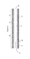
- FIGs 1 and 2 illustrate a typical honeycomb-type flow through substrate that can be used in the articles of the invention.
- the honeycomb flow through substrate 10 has an outer surface 12, an inlet end 14 and an outlet end 14'.
- the catalyst is coated on the wall elements so that the gases flowing through the passages contact the catalyst.
- the substrate has different coated zones 20 (inlet zone) and 21 (outlet zone) along the length of the passages. In the embodiment shown in Figure 2 , there is also a short, uncoated zone 22 between the coated zones.
- Figure 4 depicts a single passage of a zoned coated honeycomb flow through substrate 10 having an inlet end 14, an outlet end 14', wall elements 18, a passage defined by the wall elements 16, an inlet zone 20 and a outlet zone 21.
- the inlet zone has an SCR catalyst composition 28 disposed on the wall elements from the inlet end toward the outlet end to a length that is less than the substrate's axial length.
- the outlet zone has an NH 3 destruction catalyst composition 29 disposed on the wall elements from the outlet end toward the inlet end to a length that is less then the substrate's axial length.
- An uncoated segment of the wall elements forms an uncoated zone 22 along the axial length of the substrate.
- One embodiment of the inventive emissions treatment system denoted as 10A is schematically depicted in Figure 3A .
- the exhaust containing gaseous pollutants (including unburned hydrocarbons, carbon monoxide and NOx) and particulate matter, is conveyed from the engine 19 to a position downstream in the exhaust system where a reductant, i.e., ammonia or an ammonia-precursor, is added to the exhaust stream.
- the reductant is injected as a spray via a nozzle (not shown) into the exhaust stream.
- Aqueous urea shown on one line 25 can serve as the ammonia precursor which can be mixed with air on another line 26 in a mixing station 24.
- Valve 23 can be used to meter precise amounts of aqueous urea which are converted in the exhaust stream to ammonia.
- the exhaust stream with the added ammonia is conveyed to the zoned SCR-NH 3 destruction catalyst substrate 12 (also referred to herein including the claims as "the first substrate").
- the NOx component of the exhaust stream is converted through the selective catalytic reduction of NOx with NH 3 to N 2 and H 2 O.
- excess NH 3 that emerges from the inlet zone is converted through oxidation in the outlet zone to N 2 and H 2 O.
- other components of the exhaust are combusted by the action of the SCR catalyst and NH 3 destruction catalyst.
- the first substrate is typically a flow through monolith substrate.
- FIG. 3B An alternative embodiment of the emissions treatment system, denoted as 11B is depicted in Figure 3B which contains a second substrate 27 interposed between the NH 3 injector and the first substrate 12.
- the second substrate is coated with an SCR catalyst composition which may be the same composition as is used to coat the first substrate 13 or a different composition.
- SCR catalyst compositions that are used to coat the substrate can be selected to optimize NOx conversion for the operating conditions characteristic of that site along the exhaust system.
- the second substrate can be coated with an SCR catalyst composition that is better suited for higher operating temperatures experienced in upstream segments of the exhaust system, while another SCR composition can be used to coat the first substrate (i.e., the inlet zone of the first substrate) that is better suited to cooler exhaust temperature which are experienced in downstream segments of the exhaust system.
- an SCR catalyst composition that is better suited for higher operating temperatures experienced in upstream segments of the exhaust system
- another SCR composition can be used to coat the first substrate (i.e., the inlet zone of the first substrate) that is better suited to cooler exhaust temperature which are experienced in downstream segments of the exhaust system.
- the second substrate 27 can either be a honeycomb flow through substrate, an open cell foam substrate or a honeycomb wall flow substrate.
- the system can remove greater than 80% of the particulate matter including the soot fraction and the SOF.
- an oxidation catalyst upstream of the site of ammonia/ammonia precursor injection.
- an oxidation catalyst is disposed on a catalyst substrate 34.
- the emissions treatment system 11C is provided with the first substrate 12 and optionally includes a second substrate 27.
- the exhaust stream is first conveyed to the catalyst substrate 34 where at least some of the gaseous hydrocarbons, CO and particulate matter are combusted to innocuous components.
- a significant fraction of the NO of the NOx component of the exhaust is converted to NO 2 . Higher proportions of NO 2 in the NOx component facilitate the reduction of NOx to N 2 and H 2 O on the SCR catalyst(s) located downstream.
- compositions disclosed in the '917 patent include one or both of an iron and a copper promoter present in a zeolite in an amount of from about 0.1 to 30 percent by weight, preferably from about 1 to 5 percent by weight, of the total weight of promoter plus zeolite.
- the disclosed compositions can also promote the oxidation of excess NH 3 with O 2 , especially for those compositions having higher promoter concentrations.
- Zeolites used in such compositions are resistant to sulfur poisoning, sustain a high level of activity for the SCR process, and are capable of oxidation of excess ammonia with oxygen.
- These zeolites have pore size large enough to permit adequate movement of the reactant molecules NOx and NH 3 in to, and the product molecules N 2 and H 2 O out of, the pore system in the presence of sulfur oxide molecules resulting from short term sulfur poisoning, and/or sulfate deposits resulting from long term sulfur poisoning.
- the pore system of suitable size is interconnected in all three crystallographic dimensions.
- the crystalline structure of zeolites exhibits a complex pore structure having more or less regularly recurring connections, intersections and the like.
- Pores having a particular characteristic are said to be one dimensional if those pores do not intersect with other like pores. If the pores intersect only within a given plane with other like pores, the pores of that characteristic are said to be interconnected in two (crystallographic) dimensions. If the pores intersect with other like pores lying both in the same plane and in other planes, such like pores are said to be interconnected in three dimensions, i.e., to be "three dimensional".
- zeolites which are highly resistant to sulfate poisoning and provide good activity for both the SCR process and the oxidation of ammonia with oxygen, and which retain good activity even when subject to high temperatures, hydrothermal conditions and sulfate poisons, are zeolites which have pores which exhibit a pore diameter of at least about 7 Angstroms and are interconnected in three dimensions.
- any zeolites meeting the foregoing criteria are suitable for use in the practices of the present invention; specific zeolites which meet these criteria are USY, Beta and ZSM-20. Other zeolites may also satisfy the aforementioned criteria.
- SCR catalyst compositions When deposited on monolith substrates, such SCR catalyst compositions are deposited at a concentration of at least 1.3 g/in 3 to ensure that the desired NOx reduction and particulate removal levels are achieved and to secure adequate durability of the catalyst over extended use. In a preferred embodiment, there is at least 1.8 g/in 3 of SCR composition, and in particular, 1.8 to 2.6 g/in 3 , disposed on the monolith.
- the SCR catalyst composition that is coated on the zone-coated monolith is a copper-exchanged zeolite.
- Such compositions typically have an effective SCR catalyst operating temperature range of from 150 to 550°C.
- Suitable SCR catalyst compositions include vanadia-based SCR compositions.
- a preferred SCR catalyst is a mixed oxide composition of V 2 O 5 /WO 3 /TiO 2 .
- Such vanadia-based compositions have an effective operating range of from 200 to 500°C.
- Suitable vanadia-based compositions are also disclosed, for example, in United States Patent No. 4,883,113 ("the '113 patent).
- Catalyst compositions disclosed in the '113 patent contain oxides of titanium, tungsten and vanadium as active ingredients, and can be formed onto carrier components that include natural and synthetic zeolites, silica-alumina, silica-magnesia, silica-alumina-magnesia, silica, and titania-silica.
- the NH 3 destruction catalyst is composed of a platinum group metal component dispersed on a refractory inorganic oxide support.
- the platinum group metal component is typically present at from 0.1 to 10 g/ft 3 , and preferably, from 0.5 to 5 g/ft 3 . At these concentrations the platinum group metal component is effective for the oxidation of ammonia to form N 2 , but has a diminished propensity to cause oxidation of ammonia to form NOx. As described above, higher concentrations of platinum in the composition are liable to promote the conversion of excess ammonia to NOx and not to N 2 . Moreover, lower levels of platinum group metal components are desired to minimize the formation of sulfates that contribute to the mass of the particulate matter that is discharged to the atmosphere.
- platinum group metal components include platinum, palladium, rhodium and iridium components. Most preferably the platinum group metal component is a platinum component.
- the platinum component can be sulfated to further moderate the catalytic activity of the platinum component and control NOx formation.
- the sulfation can be performed by treatment of the composition with sulfuric acid, or alternatively, by subjecting the final coated composition to an exhaust stream derived from an internal combustion engine that uses fuel that contains higher levels of sulfur component (e.g., > 350 ppm).
- a preferred NH 3 destruction catalyst material is composed of platinum dispersed on one or both of bulk ceria and activated alumina. Such compositions are similar to those described in United States Patent No. 5,462,907 , the disclosure of which is hereby incorporated by reference.
- the catalytic material can be prepared in the form of an aqueous slurry of ceria and alumina particles, the particles being impregnated with a water-dispersible or water-soluble platinum precursor. The slurry can then applied to the carrier, dried and calcined to form a catalytic material coating ("washcoat”) thereon.
- the ceria and alumina particles are mixed with water and an acidifier such as acetic acid, nitric acid or sulfuric acid, and ball milled to a desired particle size.
- an acidifier such as acetic acid, nitric acid or sulfuric acid
- the slurry can be dried and calcined before being coated on the carrier.
- the platinum catalytic metal component is preferably incorporated into the ceria particles or into the ceria and alumina particles.
- the ceria-alumina acts not only as a catalyst but also as a support for the platinum catalytic metal component.
- Such incorporation with the platinum precursor can also be conducted after the ceria-alumina catalytic material is coated as a washcoat onto a suitable carrier, by impregnating the coated carrier with a solution of a suitable platinum precursor, followed by drying and calcination.
- the ceria particles or both the ceria and alumina particles are impregnated with a suitable platinum precursor before a coating of the ceria-alumina catalytic material is applied to the carrier.
- the platinum metal is added to the ceria-alumina catalytic material as, e.g., a solution of a soluble platinum compound, the solution serving to impregnate the ceria and alumina particles (or the ceria-alumina coating on the carrier), which may then be dried and the platinum fixed thereon. Fixing can be carried out by calcination or by treatment with hydrogen sulfide or by other known means, to render the metal in water-insoluble form.
- the slurry of ceria and activated alumina particles, with the platinum solution will be deposited upon the carrier substrate and dried and calcined to adhere the catalytic material to the carrier and, to revert the platinum compound to the elemental metal or its oxide.
- Suitable platinum precursors for use in the foregoing process include potassium platinum chloride, ammonium platinum thiocyanate, amine-solubilized platinum hydroxide and chloroplatinic acid, as is well-known in the art.
- the proportions of ingredients are conventionally expressed as weight of material per gross unit volume of catalyst, as this measure accommodates the presence of different cell densities, wall thicknesses, gas flow passages, etc.
- Grams per cubic inch (“g/in 3 ”) units are used to express the quantity of relatively plentiful components such as the ceria-alumina catalytic material, and grams per cubic foot (“g/ft 3 ”) units are used to express the quantity of the sparsely used ingredients, such as the platinum metal.
- the ceria-alumina catalytic material of the present invention generally may comprise from about 0.25 to about 4.0 g/in 3 , preferably from about 0.25 to about 3.0 g/in 3 of the coated carrier substrate, and from about 0.1 to 10 g/ft 3 of platinum.
- thermal stabilizers for the alumina e.g., rare earth metal oxides such as ceria.
- thermal stabilizers for the alumina, e.g., rare earth metal oxides such as ceria.
- thermal stabilizers may be incorporated into the bulk ceria or into the bulk activated alumina, by impregnating the ceria (or alumina) particles with, e.g., a solution of a soluble compound of the stabilizer metal, for example, an aluminum nitrate solution in the case of stabilizing bulk ceria. Such impregnation is then followed by drying and calcining the impregnated ceria particles to convert the aluminum nitrate impregnated therein into alumina.
- the catalyst compositions of the invention may contain other catalytic ingredients such as other base metal promoters or the like.
- the catalyst composition of the present invention consists essentially only of the high surface area ceria and high surface area alumina, preferably present in a weight proportion of 1.5:1 to 1:1.5, with or without thermal stabilizers impregnated therein, and, from 0.1 to 10 g/ft 3 of platinum.
- the zoned SCR-NH 3 destruction catalyst substrate has an inlet zone formed with a vanadium based SCR catalyst composition, V 2 O 5 /WO 3 /TiO 2 , and an outlet zone formed with platinum-based NH 3 destruction catalyst composition, Pt/CeO 2 /Al 2 O 3 .
- a desirable feature of this configuration is that the platinum-based composition, in addition to its NH 3 oxidation activity, can also reduce NOx at lower temperature ranges where the vanadium-based composition is ineffective. This catalytic property widens the effective temperature range of the article over which NOx can be converted to N 2 .
- the zoned SCR-NH 3 destruction catalyst substrate has an inlet zone formed with a copper-exchanged beta zeolite composition and an outlet zone formed with platinum-based NH 3 destruction catalyst composition, Pt/CeO 2 /Al 2 O 3 .
- the space velocity of the combined SCR and NH 3 destruction catalyst is typically from 5,000 to 100,000 hr -1 , and preferably, from 30,000 to 90,000 hr -1 . In any application there will be a range of space velocities, resulting from the operating range of the engine or exhaust source.
- the catalyst system in a passenger car for instance, will typically operate at higher space velocities compared to a heavy duty truck.
- the space velocity of the exhaust gas through the outlet zone alone (NH 3 destruction zone) is typically between 40,000 to 200,000 hr -1 , and preferably between 50,000 to 150,000 hr -1 .
- higher space velocities are more preferable at exhaust temperatures above 350°C.
- Lower space velocities corresponding to a larger NH 3 destruction zone (outlet zone) are less desirable due to increased costs associated with higher platinum group metal usage.
- the Carrier (Substrate)
- the carriers used for the first substrate should be relatively inert with respect to the catalytic composition dispersed thereon.
- Preferred carriers are composed of ceramic-like materials such as cordierite, ⁇ -alumina, silicon nitride, silicon-carbide, zirconia, mullite, spodumene, alumina-silica-magnesia or zirconium silicate, or of refractory metals such as stainless steel.
- the carriers are preferably of the type sometimes referred to as honeycomb or monolithic carriers, comprising a unitary cylindrical body having a plurality of fine, substantially parallel gas flow passages extending through and connecting both end-faces of the carrier to provide a "flow-through" type of carrier.
- Such monolithic carriers may contain up to about 700 or more flow channels ("cells”) per square inch of cross section, although far fewer may be used.
- the carrier may have from about 7 to 900, more usually from about 200 to 400, cells per square inch (“cpsi").
- the second substrate may be of the flow through type or an open-cell foam filter as described above, or it may be of wall flow type.
- Wall flow substrates useful for supporting the SCR catalyst compositions have a plurality of fine, substantially parallel gas flow passages extending along the longitudinal axis of the substrate. Typically, each passage is blocked at one end of the substrate body, with alternate passages blocked at opposite end-faces.
- Such monolithic carriers may contain up to about 700 or more flow passages (or "cells") per square inch of cross section, although far fewer may be used.
- the carrier may have from about 7 to 600, more usually from about 100 to 400, cells per square inch (“cpsi").
- the cells can have cross sections that are rectangular, square, circular, oval, triangular, hexagonal, or are of other polygonal shapes.
- Wall flow substrates typically have a wall thickness between 0.002 and 0.1 inches.
- Preferred wall flow substrates have a wall thickness of between 0.002 and 0.015 inches.
- Useful wall flow filters which can be used for the second substrate are discussed in co-pending United States Patent Application Serial No. 10/634,659, filed August 5, 2003 .
- the second substrate can be an open cell foam substrate that contains a plurality of pores.
- Figure 5 illustrates a cutaway section of a typical substrate of the foam-type.
- the foam 33 is an open-celled foam and the catalyst coating 30 is deposited on the walls 32 of the cells 31.
- the open-celled structure of the foam provides the coated substrate with a high surface area of the catalyst per volume.
- An exhaust stream passing through the substrate from the inlet end to the outlet end of the substrate flows through though the plurality of cells defined by the walls of the foam to contact the catalyst layer deposited on the walls of the cells.
- the foam substrate may be composed of metallic or ceramic materials. Examples of ceramic foams are disclosed in United States Patent No. 6,077,600 , which is herein incorporated by reference. Ceramic foam carriers have walls formed from fibers coated with ceramic materials. Substrates in the form of metal foams are well known in the prior art, e.g., see United States Patent No. 3,111,396 , which is herein incorporated by reference.
- the zone coated article can be prepared by disposing the SCR catalyst composition and NH 3 destruction catalyst composition on a honeycomb flow through substrate.
- the SCR catalyst composition can be combined with water and comminuted to achieve an average particle size of ⁇ 10 ⁇ to form a washcoat composition.
- the washcoat slurries are deposited on the substrates by methods well-known to those of ordinary skill.
- a layer of the SCR catalyst can be prepared by dipping the substrate from the inlet end in a reservoir containing a sufficient volume of the washcoat slurry so that the substrate is coated to a desired length of the substrate to form the inlet zone.
- the coated substrate can be subsequently dried.
- the outlet end of the substrate is dipped into a slurry containing the finely comminuted NH 3 destruction catalyst slurry to the desired length.
- the entire substrate is then dried and calcined.
- a gap of at least 0.25 inches is left between the two catalyst zone to avoid contamination of the two catalyst compositions, and any potential loss of catalytic activity caused by mixture of the two compositions.
- a reductant dosing system is provided upstream of the zoned SCR-NH 3 destruction catalyst to inject a NOx reductant into the exhaust stream.
- NOx upstream and downstream of the catalytic converter can be sensed, and a pulsed dosing valve can be controlled by the upstream and downstream signals.
- the systems disclosed in United States Patent No. 5,522,218 where the pulse width of the reductant injector is controlled from maps of exhaust gas temperature and engine operating conditions such as engine rpm, transmission gear and engine speed.
- reductant pulse metering systems in United States Patent No. 6,415,602 , the discussion of which is hereby incorporated by reference. Normally, the amount of ammonia or ammonia precursor metered into the exhaust stream provides a normalized stoichiometric ratio of between 0.2 to 2.0.
- Example 1 Preparation of Zoned Substrate with an Inlet Zone Having a Copper-Exchanged Beta-Zeolite Catalyst Composition and an Outlet Zone Having a Platinum-Containing Catalyst (Catalyst Substrate A1).
- Catalyst Substrate A1 was a zone coated catalyst substrate containing an inlet zone having a copper-exchanged beta-zeolite catalyst composition as an SCR catalyst and an outlet zone containing platinum-containing catalyst composition as an NH 3 destruction catalyst.
- Preparation of the washcoat slurry (Slurry B3) used to form the NH 3 destruction catalyst is described below.
- First a slurry containing platinum dispersed on bulk ceria was prepared (Slurry B1).
- Bulk ceria (2758.72 g) was combined with sufficient water to form a slurry containing 60% by weight of solids.
- An aqueous solution of amine-solubilized platinum hydroxide (17.68 g) was added to the slurry, and the resulting slurry was mixed for 5 min.
- Acetic acid (7.0% by weight of ceria solids) and surfactant (0.05% by weight of total solids) were added to the slurry and the slurry was milled continuously so that 90% of the particles had a particle size of 8 microns.
- a slurry containing platinum dispersed on bulk ceria was prepared (Slurry B2).
- Gamma alumina 3238.50 g was combined with sufficient water to form a slurry containing 50% by weight of solids.
- An aqueous solution of amine-solubilized platinum hydroxide (17.68 g) was added to the slurry, and the resulting slurry was mixed for 10 min.
- 90% Acetic acid (7.5% by weight of alumina solids) and surfactant (0.07% by weight of total solids) were added to the slurry and the slurry was milled continuously so that 90% of the particles had a particle size of 8 microns.
- Slurry B1 and Slurry B2 were combined and mixed for 10 min to for Slurry B3.
- Slurry B3 was diluted with more water to form a washcoat slurry containing 50% by weight of solids.
- Slurries A1 and B3 were used to coat a 400 cpsi, 9.5 in diameter x 7.5 in long cordierite honeycomb substrate.
- the NH 3 destruction catalyst was applied to the substrate using a two coat process.
- the outlet end of the substrate was dipped into Slurry B3 to a depth of about 2 in.
- the coated substrate was removed from the dipping tank and excess slurry was allowed to drain off.
- pressurized air was passed through the substrate. The draining and the air blowing steps were conducted carefully to prevent the slurry from contacting the uncoated segment of the substrate.
- the substrate was dried and calcined.
- the second coat of Slurry B3 was then applied in identical fashion, and again the substrate was dried and calcined.
- the SCR catalyst composition was applied to the substrate's inlet end.
- the inlet end of the substrate was dipped into Slurry A1 to a depth of about 5 in.
- a gap of 0.5 in was thereby left between the two coating zones.
- the coated substrate was removed from the dipping tank and excess slurry was allowed to carefully drain off. Again pressurized air was carefully passed through the substrate to avoid contacting the outlet zone with Slurry A1.
- the substrate was dried and calcined.
- the second coat of Slurry A1 was then applied in identical fashion, and again, the substrate was dried and calcined.
- the inlet zone of the final coated substrate contained 2.15 g/in 3 of copper ⁇ -zeolite (0.07 g/in 3 of copper), and 0.10 g/in 3 of ZrO 2 .
- the outlet zone of the final coated substrate contained 1.35 g/in 3 of Al 2 O 3 , 1.15 g/in 3 of CeO 2 , and 2 g/ft 3 ofPt.
- This coated substrate was designated as Catalyst Substrate A-1.
- Example 2 Preparation of Zoned Substrate with an Inlet Zone Having a Vanadium-Based Catalyst Composition and an Outlet Zone Having a Platinum-Containing Catalyst -Substrate D-1.
- Substrate D-1 was a zone coated substrate containing an inlet zone having a vanadium-based catalyst composition as an SCR catalyst and an outlet zone containing a platinum-containing catalyst composition as an NH 3 destruction catalyst.
- washcoat slurry (Slurry C1) used to form the SCR catalyst is described below.
- Ammonium metavanadate (2001.96 g) was added to a heated solution of citric acid in water. The mixture was agitated for 30 min and then cooled to room temperature. Colloidal silica (4666.57 g) and additional water were added to the cooled mixture, and the resulting mixture was mixed for 5 min using a high shear mixer. A first portion of 10 wt.% tungsten (VI) oxide dispersed on titanium dioxide (74665.17 g) was added to the mixture and the resulting mixture was mixed for 5 min.
- VI tungsten
- Ammonium hydroxide was added in increments to adjust the pH of the mixture to 5.0 - 5.5, and mixing was continued for an additional 5 min.
- a second portion of 10 wt.% tungsten oxide dispersed on titanium dioxide (18666.29 g) was added to the mixture, and the resulting mixture was mixed for 5 min.
- Ammonium hydroxide was added incrementally to adjust the pH of the mixture to 5.0 - 5.5, and mixing was continued for an additional 5 min.
- Ammonium salt of polyacrylic acid was added in increments to adjust the viscosity of the mixture. Additional water was added to achieve a solids content of 41% by weight. The resulting slurry was designated as Slurry C1.
- Slurries C1 and B3 (prepared as described above in Example 1) were used to coat a 400 cpsi, 10.5 in diameter x 6 in long cordierite honeycomb substrate.
- the NH 3 destruction catalyst was applied to the substrate using a two coat process. The outlet end of the substrate was dipped into Slurry B3 to a depth of 2 in. The coated substrate was removed from the dipping tank and excess slurry was carefully allowed to drain off. Pressurized air was passed through the substrate carefully to avoid contact of Slurry B3 with the upstream zone. The substrate was dried and calcined. The second coat of Slurry B3 was then applied in identical fashion, and again the substrate was dried and calcined.
- the SCR catalyst composition was applied to the substrate's inlet end using a two coat process.
- the inlet end of the substrate was dipped into Slurry C1 to a depth of 3.5 in.
- pressurized air was passed through the substrate.
- the draining and the air blowing steps were conducted carefully to prevent the slurry from contacting other segments of the substrate.
- the substrate was dried and calcined.
- the second coat of Slurry C1 was then applied in identical fashion, and the substrate was dried and calcined.
- the inlet zone of the final coated substrate contained 2.33 g/in 3 of WO 3 onTiO 2 , and 0.05 g/in 3 of V 2 O 5 , 0.12 g/in 3 of SiO 2 .
- the outlet zone of the final coated substrate contained 1.35 g/in 3 of Al 2 O 3 , 1.15 g/in 3 of CeO 2 , and 2 g/ft 3 ofPt.
- This coated substrate was designated as Catalyst Substrate B-1.
- Samples for evaluation were previously cut cores or were cored from larger pieces using the full length of the substrate. Each sample was approximately 1 inch in diameter. Prior to testing the honeycombs were trimmed to an approximately square cross section and total number of cells exposed to the gas flow were counted. Knowing the number of open cells, the "honeycomb cell density" (cells per square inch) and the sample length, it was possible to accurately determine the gas flow to achieve a targeted space velocity.
- the space velocity has units of 1/hours (hr -1 ) and was calculated with the gas flow referred to engineering standard conditions (20°C, 1 atm). To ensure that gas flows only though the sample, a ceramic felt was wrapped around the sample and then the whole assembly was press fit into a metal sample holder.
- Evaluations were conducted using a test gas composition containing 500 ppm ammonia, 500 ppm of NO, 10% oxygen, 5% water vapor and the balance nitrogen. NOx and ammonia was measured at the catalyst inlet and outlet. The space velocity of the test gas composition was 60,000 hr -1 . The temperature range tested in the trials was 200 to 450°C. In evaluating the catalyst's ability to treat NOx, catalyst performance was reported as the NOx conversion, based on the inlet NO concentration. In evaluating the catalyst's performance ability to treat ammonia, catalyst performance was reported as the percentage disappearance of ammonia, along with the percentage removal of NO (or percentage make), based on the inlet ammonia concentrations. Data generated for %NOx conversion is shown in Figure 6 . Data generated for NH 3 removal is shown in Figure 7 .
- Catalyst Substrate A1 was placed in the sample holder in the conventional direction, where the first zone encountering the test gas composition contained the SCR catalyst composition.
- the data curve generated by placing the substrate in the sample holder in this direction is designated as "Conventional" in Figures 6-7 .
- Catalyst Substrate A1 was placed in the sample holder in the reversed direction, where the first zone encountering the test gas composition contained the NH 3 destruction catalyst composition.
- the data curve generated by placing the substrate in the sample holder in this direction is designated as "Reversed” in Figures 6-7 .
- Catalyst Substrate A1 verifies the zone coating concept with respect to NOx conversion and NH 3 conversions.
- Catalyst Substrate A1 showed both significant NOx conversion and NH 3 removal efficiencies at temperatures of 250 to 450°C, which temperatures are typically encountered in diesel engine exhaust applications.
- Samples for evaluation were cored from larger pieces. Each sample was approximately 1 inch in diameter and six inches long. Prior to testing, the sample was trimmed to an approximately square cross section and the number of cells exposed to the gas flow was counted. Knowing the number of open cells, the "honeycomb cell density" (cells per square inch) and the sample length, it was possible to accurately determine the gas flow to achieve a targeted space velocity.
- the space velocity has units of 1/hours (hr -1 ) and was calculated with the gas flow referred to engineering standard conditions (20°C, 1 atm). To ensure that gas flows only though the sample, a ceramic felt was wrapped around the sample and then the whole assembly is press fit into a metal sample holder.
- Test gas compositions used in the evaluations contained 1000 ppm ammonia, supplied as ammonia in nitrogen, 10% oxygen, 5% water vapor and the balance nitrogen. In some tests nitric oxide (NO) was not added, but in all tests NO, NO 2 and N 2 O were measured at the catalyst inlet and outlet. Catalyst performance was reported as the percentage disappearance of ammonia, along with the percentage removal of NO (or percentage make), based on the inlet NO and ammonia concentrations.
- NO nitric oxide
- catalyst substrates containing 0.5, 2.0 and 5.0 g/ft 3 of Pt were evaluated in the test gas stream at inlet temperatures ranging from 150 to 400°C.
- the test gas was run at a space velocity of 50,000 hr -1 ( Figure 8 ) and 100,000 hr -1 ( Figure 9 ).
- Figures 8-9 there is a 50 to 60°C improvement in the ammonia light off temperature by increasing the Pt from 0.5 to 2.0 g/ft 3 at 50,000 and 100,000 hr -1 .
- increasing the Pt loading from 2 to 5 g/ft 3 did not further improve the light off.
- NOx make increased with increasing Pt concentrations and increasing temperature.
- Figure 10 shows the %NH 3 removal, %NOx make and N 2 O produced (ppm) when the test gas composition was passed through a catalyst substrate containing 2.0 g/ft 3 of Pt at 50,000 hr -1 and 100,000 hr -1 .
- 50% NH 3 removal was achieved at 220°C @ 50,000 hr -1
- 50% NH 3 removal was achieved at 240°C.
- the extent of NOx make was almost independent of space velocity.
- the NOx make was between 30 to 40%.
- the amount of N 2 O formed was greater at 100,000 hr -1 than at 50,000 hr -1 .
Landscapes
- Engineering & Computer Science (AREA)
- Chemical & Material Sciences (AREA)
- Chemical Kinetics & Catalysis (AREA)
- Combustion & Propulsion (AREA)
- Mechanical Engineering (AREA)
- General Engineering & Computer Science (AREA)
- Health & Medical Sciences (AREA)
- Materials Engineering (AREA)
- Organic Chemistry (AREA)
- Biomedical Technology (AREA)
- Analytical Chemistry (AREA)
- General Chemical & Material Sciences (AREA)
- Oil, Petroleum & Natural Gas (AREA)
- Environmental & Geological Engineering (AREA)
- Toxicology (AREA)
- Catalysts (AREA)
- Exhaust Gas After Treatment (AREA)
- Exhaust Gas Treatment By Means Of Catalyst (AREA)
Priority Applications (1)
| Application Number | Priority Date | Filing Date | Title |
|---|---|---|---|
| PL13178810T PL2664379T3 (pl) | 2004-08-23 | 2005-08-22 | Katalizator pokryty strefowo do równoczesnego zmniejszania zawartości nox i nieprzereagowanego amoniaku |
Applications Claiming Priority (3)
| Application Number | Priority Date | Filing Date | Title |
|---|---|---|---|
| US10/925,018 US7481983B2 (en) | 2004-08-23 | 2004-08-23 | Zone coated catalyst to simultaneously reduce NOx and unreacted ammonia |
| PCT/US2005/029992 WO2006023932A1 (fr) | 2004-08-23 | 2005-08-22 | CATALYSEUR IMPRÉGNÉ PAR ZONES POUR RÉDUIRE SIMULTANÉMENT LES NOx ET L'AMMONIAC NON TRANSFORMÉ |
| EP05793942.3A EP1784258B1 (fr) | 2004-08-23 | 2005-08-22 | CATALYSEUR IMPRÉGNÉ PAR ZONES, SYSTÈME DE CATALYSEUR ET PROCÉDÉ POUR RÉDUIRE SIMULTANÉMENT LES NOx ET L'AMMONIAC NON TRANSFORMÉ |
Related Parent Applications (2)
| Application Number | Title | Priority Date | Filing Date |
|---|---|---|---|
| EP05793942.3A Division EP1784258B1 (fr) | 2004-08-23 | 2005-08-22 | CATALYSEUR IMPRÉGNÉ PAR ZONES, SYSTÈME DE CATALYSEUR ET PROCÉDÉ POUR RÉDUIRE SIMULTANÉMENT LES NOx ET L'AMMONIAC NON TRANSFORMÉ |
| EP05793942.3A Division-Into EP1784258B1 (fr) | 2004-08-23 | 2005-08-22 | CATALYSEUR IMPRÉGNÉ PAR ZONES, SYSTÈME DE CATALYSEUR ET PROCÉDÉ POUR RÉDUIRE SIMULTANÉMENT LES NOx ET L'AMMONIAC NON TRANSFORMÉ |
Publications (3)
| Publication Number | Publication Date |
|---|---|
| EP2664379A1 true EP2664379A1 (fr) | 2013-11-20 |
| EP2664379B1 EP2664379B1 (fr) | 2019-05-22 |
| EP2664379B2 EP2664379B2 (fr) | 2024-09-04 |
Family
ID=35431191
Family Applications (2)
| Application Number | Title | Priority Date | Filing Date |
|---|---|---|---|
| EP05793942.3A Active EP1784258B1 (fr) | 2004-08-23 | 2005-08-22 | CATALYSEUR IMPRÉGNÉ PAR ZONES, SYSTÈME DE CATALYSEUR ET PROCÉDÉ POUR RÉDUIRE SIMULTANÉMENT LES NOx ET L'AMMONIAC NON TRANSFORMÉ |
| EP13178810.1A Active EP2664379B2 (fr) | 2004-08-23 | 2005-08-22 | Catalyseur imprégné par zones pour réduire simultanément le NOx et l'ammoniac n'ayant pas réagi |
Family Applications Before (1)
| Application Number | Title | Priority Date | Filing Date |
|---|---|---|---|
| EP05793942.3A Active EP1784258B1 (fr) | 2004-08-23 | 2005-08-22 | CATALYSEUR IMPRÉGNÉ PAR ZONES, SYSTÈME DE CATALYSEUR ET PROCÉDÉ POUR RÉDUIRE SIMULTANÉMENT LES NOx ET L'AMMONIAC NON TRANSFORMÉ |
Country Status (8)
| Country | Link |
|---|---|
| US (2) | US7481983B2 (fr) |
| EP (2) | EP1784258B1 (fr) |
| KR (1) | KR101201563B1 (fr) |
| ES (2) | ES2739818T3 (fr) |
| PL (2) | PL2664379T3 (fr) |
| PT (2) | PT2664379T (fr) |
| TR (1) | TR201909520T4 (fr) |
| WO (1) | WO2006023932A1 (fr) |
Cited By (1)
| Publication number | Priority date | Publication date | Assignee | Title |
|---|---|---|---|---|
| WO2015128247A1 (fr) * | 2014-02-28 | 2015-09-03 | Haldor Topsøe A/S | Procédé de nettoyage de gaz d'échappement d'un moteur à allumage par compression |
Families Citing this family (131)
| Publication number | Priority date | Publication date | Assignee | Title |
|---|---|---|---|---|
| EP1458960B1 (fr) * | 2001-12-20 | 2011-02-09 | Johnson Matthey Public Limited Company | Ameliorations dans la reduction catalytique selective |
| GB0318776D0 (en) * | 2003-08-09 | 2003-09-10 | Johnson Matthey Plc | Lean NOx catalyst |
| JP2005334801A (ja) * | 2004-05-28 | 2005-12-08 | Cataler Corp | 排ガス浄化用触媒 |
| JP2006057578A (ja) * | 2004-08-23 | 2006-03-02 | Hino Motors Ltd | 排気浄化装置 |
| US7481983B2 (en) | 2004-08-23 | 2009-01-27 | Basf Catalysts Llc | Zone coated catalyst to simultaneously reduce NOx and unreacted ammonia |
| DE102005017402A1 (de) * | 2005-04-15 | 2006-10-19 | Emitec Gesellschaft Für Emissionstechnologie Mbh | Verfahren und Vorrichtung zur dosierten Bereitstellung eines, insbesondere als Feststoff vorliegenden, Reduktionsmittels für Abgassysteme |
| KR100765413B1 (ko) * | 2005-07-06 | 2007-10-09 | 희성촉매 주식회사 | 암모니아 산화촉매 및 이를 이용한 슬립 암모니아 또는폐암모니아 처리장치 |
| ATE444807T1 (de) * | 2005-08-05 | 2009-10-15 | Basf Catalysts Llc | Dieselabgasartikel und katalysatorzusammensetzungen dafür |
| GB0523135D0 (en) * | 2005-11-14 | 2005-12-21 | Johnson Matthey Plc | Reducing coking over Ag/A1203 HC-SCR catalyst |
| DE102006011411B3 (de) * | 2006-03-11 | 2007-11-29 | Argillon Gmbh | Katalysator |
| US7576031B2 (en) * | 2006-06-09 | 2009-08-18 | Basf Catalysts Llc | Pt-Pd diesel oxidation catalyst with CO/HC light-off and HC storage function |
| DE102006031724B3 (de) * | 2006-07-08 | 2008-04-30 | Umicore Ag & Co. Kg | Strukturierter SCR-Katalysator zur Reduktion von Stickoxiden im Abgas von Magermotoren unter Verwendung von Ammoniak als Reduktionsmittel |
| KR101362685B1 (ko) | 2006-07-08 | 2014-02-13 | 우미코레 아게 운트 코 카게 | 환원제로서 암모니아를 사용하여 희박 혼합 기관의 배기 가스로부터의 질소 산화물을 환원시키기 위한 구조화된 scr 촉매 |
| US20080053071A1 (en) * | 2006-09-05 | 2008-03-06 | Karen Adams | System and Method for Reducing NOx Emissions |
| DE102006048045A1 (de) * | 2006-10-11 | 2008-04-17 | Daimler Ag | Abgasreinigungsanlage für eine Brennkraftmaschine |
| US20080127638A1 (en) * | 2006-12-01 | 2008-06-05 | Marius Vaarkamp | Emission Treatment Systems and Methods |
| US8800268B2 (en) * | 2006-12-01 | 2014-08-12 | Basf Corporation | Zone coated filter, emission treatment systems and methods |
| JP5618543B2 (ja) * | 2006-12-23 | 2014-11-05 | アルツケム アクチエンゲゼルシャフトAlzChem AG | 排ガス中の窒素酸化物の選択的接触還元法 |
| US7527776B2 (en) * | 2007-01-09 | 2009-05-05 | Catalytic Solutions, Inc. | Ammonia SCR catalyst and method of using the catalyst |
| US8802582B2 (en) * | 2007-01-09 | 2014-08-12 | Catalytic Solutions, Inc. | High temperature ammonia SCR catalyst and method of using the catalyst |
| US7943097B2 (en) * | 2007-01-09 | 2011-05-17 | Catalytic Solutions, Inc. | Reactor system for reducing NOx emissions from boilers |
| US7767175B2 (en) * | 2007-01-09 | 2010-08-03 | Catalytic Solutions, Inc. | Ammonia SCR catalyst and method of using the catalyst |
| US7998423B2 (en) * | 2007-02-27 | 2011-08-16 | Basf Corporation | SCR on low thermal mass filter substrates |
| JP5683111B2 (ja) * | 2007-02-27 | 2015-03-11 | ビーエーエスエフ コーポレーション | 銅chaゼオライト触媒 |
| KR101974704B1 (ko) * | 2007-02-27 | 2019-05-02 | 바스프 카탈리스트 엘엘씨 | 선택적 암모니아 산화를 위한 이원기능 촉매 |
| CA2939726C (fr) | 2007-04-26 | 2019-06-18 | Johnson Matthey Public Limited Company | Catalyseurs de scr en metal de transition/zeolite |
| US8691170B2 (en) * | 2007-05-31 | 2014-04-08 | Siemens Energy, Inc. | System and method for selective catalytic reduction of nitrogen oxides in combustion exhaust gases |
| DE502007002874D1 (de) * | 2007-09-28 | 2010-04-01 | Umicore Ag & Co Kg | Entfernung von Partikeln aus dem Abgas von mit überwiegend stöchiometrischem Luft/Kraftstoff-Gemisch betriebenen Verbrennungsmotoren |
| US20090133383A1 (en) * | 2007-11-28 | 2009-05-28 | Shost Mark A | Selective NOx catalytic reduction system including an ammonia sensor |
| US7736608B2 (en) * | 2007-11-29 | 2010-06-15 | General Electric Company | Methods and systems for reducing the emissions from combustion gases |
| US20090196812A1 (en) * | 2008-01-31 | 2009-08-06 | Basf Catalysts Llc | Catalysts, Systems and Methods Utilizing Non-Zeolitic Metal-Containing Molecular Sieves Having the CHA Crystal Structure |
| DE102008008785A1 (de) * | 2008-02-12 | 2009-08-13 | Man Nutzfahrzeuge Aktiengesellschaft | Vorrichtung zur Verminderung von Dibenzo-Dioxin-, Dibenzo-Furan- und Partikel-Emissionen |
| DE102008008748A1 (de) * | 2008-02-12 | 2009-08-13 | Man Nutzfahrzeuge Ag | Vorrichtung zur Verminderung von Dibenzo-Dioxin- und Dibenzo-Furan-Emissionen aus übergangsmetallhaltigen Katalysatoren |
| DE102008008786A1 (de) * | 2008-02-12 | 2009-08-13 | Man Nutzfahrzeuge Aktiengesellschaft | Vorrichtung zur Verminderung von Dibenzo-Dioxin- und Dibenzo-Furan-Emissionen aus übergangsmetallhaltigen Katalysatoren |
| US8607553B2 (en) * | 2008-02-15 | 2013-12-17 | Caterpillar Inc. | Exhaust system implementing selective catalyst flow control |
| DE102008009672B4 (de) * | 2008-02-18 | 2016-02-25 | Süd-Chemie Ip Gmbh & Co. Kg | SCR-Katalysator mit Kohlenwasserstoffspeicherfunktion, dessen Verwendung und Abgasreinigungssystem und dessen Verwendung |
| ATE460973T1 (de) * | 2008-04-11 | 2010-04-15 | Umicore Ag & Co Kg | Abgasreinigungssystem zur behandlung von motorenabgasen mittels scr-katalysator |
| WO2009141895A1 (fr) * | 2008-05-20 | 2009-11-26 | イビデン株式会社 | Appareil de purification de gaz d'échappement |
| EP2138681B1 (fr) | 2008-06-27 | 2019-03-27 | Umicore AG & Co. KG | Procédé et dispositif de nettoyage de gaz d'échappement diesel |
| GB0812544D0 (en) * | 2008-07-09 | 2008-08-13 | Johnson Matthey Plc | Exhaust system for a lean burn IC engine |
| US20100077739A1 (en) * | 2008-09-30 | 2010-04-01 | Rodman Anthony C | Exhaust system implementing dual stage SCR |
| US8524185B2 (en) * | 2008-11-03 | 2013-09-03 | Basf Corporation | Integrated SCR and AMOx catalyst systems |
| DE102008055890A1 (de) * | 2008-11-05 | 2010-05-12 | Süd-Chemie AG | Partikelminderung mit kombiniertem SCR- und NH3-Schlupf-Katalysator |
| US10583424B2 (en) | 2008-11-06 | 2020-03-10 | Basf Corporation | Chabazite zeolite catalysts having low silica to alumina ratios |
| KR20100064876A (ko) * | 2008-12-05 | 2010-06-15 | 현대자동차주식회사 | 배기가스 필터 시스템 |
| US8544260B2 (en) * | 2008-12-24 | 2013-10-01 | Basf Corporation | Emissions treatment systems and methods with catalyzed SCR filter and downstream SCR catalyst |
| CN102325580B (zh) | 2008-12-24 | 2016-04-13 | 巴斯夫公司 | 具有催化scr过滤器和下游scr催化剂的排气处理系统及方法 |
| US8844274B2 (en) * | 2009-01-09 | 2014-09-30 | Ford Global Technologies, Llc | Compact diesel engine exhaust treatment system |
| US8920759B2 (en) * | 2009-03-02 | 2014-12-30 | GM Global Technology Operations LLC | Method and apparatus for reducing NOx emissions from a lean burning hydrocarbon fueled power source |
| US9662611B2 (en) | 2009-04-03 | 2017-05-30 | Basf Corporation | Emissions treatment system with ammonia-generating and SCR catalysts |
| US8637426B2 (en) * | 2009-04-08 | 2014-01-28 | Basf Corporation | Zoned catalysts for diesel applications |
| WO2010124105A1 (fr) * | 2009-04-22 | 2010-10-28 | Basf Corporation | Substrats filtrants partiels contenant des catalyseurs scr et systèmes de traitement des émissions, et procédés de traitement des gaz d'échappement de moteurs |
| IT1394068B1 (it) * | 2009-05-13 | 2012-05-25 | Milano Politecnico | Reattore per reazioni catalitiche esotermiche o endotermiche |
| US8207084B2 (en) | 2009-06-23 | 2012-06-26 | Ford Global Technologies, Llc | Urea-resistant catalytic units and methods of using the same |
| JP2011052612A (ja) * | 2009-09-02 | 2011-03-17 | Toyota Industries Corp | 排気ガス浄化装置 |
| US20110064633A1 (en) * | 2009-09-14 | 2011-03-17 | Ford Global Technologies, Llc | Multi-Functional Catalyst Block and Method of Using the Same |
| US20110064632A1 (en) * | 2009-09-14 | 2011-03-17 | Ford Global Technologies, Llc | Staged Catalyst System and Method of Using the Same |
| US8246922B2 (en) * | 2009-10-02 | 2012-08-21 | Basf Corporation | Four-way diesel catalysts and methods of use |
| WO2011061841A1 (fr) * | 2009-11-19 | 2011-05-26 | イビデン株式会社 | Structure en nid d'abeille et appareil de purification des gaz d'échappement |
| CN102666430B (zh) * | 2009-11-19 | 2015-04-29 | 揖斐电株式会社 | 蜂窝结构体以及尾气净化装置 |
| US8293199B2 (en) * | 2009-12-18 | 2012-10-23 | Basf Corporation | Process for preparation of copper containing molecular sieves with the CHA structure, catalysts, systems and methods |
| US8293198B2 (en) * | 2009-12-18 | 2012-10-23 | Basf Corporation | Process of direct copper exchange into Na+-form of chabazite molecular sieve, and catalysts, systems and methods |
| FR2954184B1 (fr) * | 2009-12-22 | 2014-05-16 | Peugeot Citroen Automobiles Sa | Monolithe de post-traitement des gaz d'echappement d'un moteur a combustion pour la filtration des particules et la reduction des oxydes d'azotes |
| US8293182B2 (en) | 2010-05-05 | 2012-10-23 | Basf Corporation | Integrated SCR and AMOx catalyst systems |
| MY163935A (en) * | 2010-05-05 | 2017-11-15 | Basf Corp | Catalyzed soot filter and emissions treatment systems and methods |
| JP5397542B2 (ja) * | 2010-05-12 | 2014-01-22 | トヨタ自動車株式会社 | 内燃機関の排気浄化システム |
| DK2603320T3 (en) * | 2010-08-09 | 2016-05-17 | Cormetech Inc | Structured catalyst body |
| SE536140C2 (sv) * | 2010-08-13 | 2013-05-28 | Scania Cv Ab | Arrangemang och förfarande för att styra mängden av ett reduktionsmedel som tillförs en avgasledning hos en förbränningsmotor |
| DE102010050312A1 (de) | 2010-11-03 | 2012-05-03 | Süd-Chemie AG | Ammoniak-Oxidationskatalysator mit geringer N2O Nebenproduktbildung |
| US20110165040A1 (en) * | 2010-11-03 | 2011-07-07 | Ford Global Technologies, Llc | Device for remediating emissions and method of manufacture |
| US8580701B2 (en) | 2010-11-19 | 2013-11-12 | Corning Incorporated | Method of controlling Ce:Zr ratio in oxide nanoparticles |
| US8304366B2 (en) | 2010-11-24 | 2012-11-06 | Ford Global Technologies, Llc | System for remediating emissions and method of use |
| US8535629B2 (en) * | 2010-12-02 | 2013-09-17 | Johnson Matthey Public Limited Company | Zeolite catalyst containing metal |
| US8591820B2 (en) | 2011-03-11 | 2013-11-26 | Corning Incorporated | Honeycomb filters for reducing NOx and particulate matter in diesel engine exhaust |
| US8101146B2 (en) * | 2011-04-08 | 2012-01-24 | Johnson Matthey Public Limited Company | Catalysts for the reduction of ammonia emission from rich-burn exhaust |
| GB2492175B (en) * | 2011-06-21 | 2018-06-27 | Johnson Matthey Plc | Exhaust system for internal combustion engine comprising catalysed filter substrate |
| US8789356B2 (en) | 2011-07-28 | 2014-07-29 | Johnson Matthey Public Limited Company | Zoned catalytic filters for treatment of exhaust gas |
| US8440155B2 (en) * | 2011-08-19 | 2013-05-14 | Corning Incorporated | Flow modulating substrates for early light-off |
| GB2493987B (en) * | 2011-08-26 | 2014-03-19 | Jc Bamford Excavators Ltd | An engine system |
| US20130047583A1 (en) * | 2011-08-31 | 2013-02-28 | Caterpillar Inc. | Aftertreatment system |
| US8735314B2 (en) | 2011-09-29 | 2014-05-27 | Celanese International Corporation | Catalysts for producing acrylic acids and acrylates |
| GB2513364B (en) | 2013-04-24 | 2019-06-19 | Johnson Matthey Plc | Positive ignition engine and exhaust system comprising catalysed zone-coated filter substrate |
| GB201207313D0 (en) | 2012-04-24 | 2012-06-13 | Johnson Matthey Plc | Filter substrate comprising three-way catalyst |
| CN102824922B (zh) * | 2012-09-07 | 2014-06-18 | 浙江天蓝环保技术股份有限公司 | 用于低温烟气脱硝的scr整体蜂窝催化剂及其制备方法 |
| KR20140062899A (ko) * | 2012-11-12 | 2014-05-27 | 현대자동차주식회사 | 차량의 배기 가스 정화장치 |
| JP5799938B2 (ja) * | 2012-11-20 | 2015-10-28 | トヨタ自動車株式会社 | 排ガス浄化用触媒 |
| GB201221025D0 (en) * | 2012-11-22 | 2013-01-09 | Johnson Matthey Plc | Zoned catalysed substrate monolith |
| EP2927444A4 (fr) * | 2012-11-28 | 2016-08-24 | Toyota Motor Co Ltd | Filtre d'épuration d'échappement |
| US10294838B2 (en) * | 2012-12-03 | 2019-05-21 | Toyota Jidosha Kabushiki Kaisha | Exhaust purification filter |
| RU2015136783A (ru) * | 2013-01-29 | 2017-03-07 | Джонсон Мэтти Паблик Лимитед Компани | Катализатор окисления аммиака |
| EP2772302A1 (fr) | 2013-02-27 | 2014-09-03 | Umicore AG & Co. KG | Catalyseur d'oxydation hexagonale |
| US9561495B2 (en) * | 2013-03-06 | 2017-02-07 | Basf Corporation | Porous catalyst washcoats |
| GB2512648B (en) | 2013-04-05 | 2018-06-20 | Johnson Matthey Plc | Filter substrate comprising three-way catalyst |
| KR101481600B1 (ko) * | 2013-05-02 | 2015-01-14 | 희성촉매 주식회사 | 선택적 촉매 환원 (scr) 시스템에서의 암모니아 산화촉매 |
| WO2015005423A1 (fr) * | 2013-07-10 | 2015-01-15 | 株式会社キャタラー | Catalyseur pour la purification de gaz d'échappement |
| EP3027309B1 (fr) * | 2013-07-30 | 2020-05-27 | Johnson Matthey Public Limited Company | Catalyseur pour fuite d'ammoniac |
| JP2015100757A (ja) * | 2013-11-26 | 2015-06-04 | 三菱重工業株式会社 | 排ガス処理触媒 |
| JP5888312B2 (ja) | 2013-11-29 | 2016-03-22 | トヨタ自動車株式会社 | 排ガス浄化用触媒 |
| KR101858685B1 (ko) * | 2014-02-28 | 2018-06-27 | 스카니아 씨브이 악티에볼라그 | 연소 엔진으로부터의 질소 산화물 배출물을 제어하기 위한 방법 및 시스템 |
| CN104028263A (zh) * | 2014-05-14 | 2014-09-10 | 无锡立信环保科技有限公司 | 一种低温scr蜂窝催化剂的制备方法 |
| GB2530129B (en) * | 2014-05-16 | 2016-10-26 | Johnson Matthey Plc | Catalytic article for treating exhaust gas |
| DE102015209988A1 (de) * | 2014-06-02 | 2015-12-03 | Johnson Matthey Public Limited Company | Beschichtete Artikel mit hohen KNOx/KSOx-Verhältnissen für die selektive katalytische Reduktion |
| CN104120508B (zh) * | 2014-06-26 | 2016-08-24 | 浙江大学 | 一种具有分级结构的金属氧化物纳米纤维及其制备方法和应用 |
| CN104226300B (zh) * | 2014-08-08 | 2016-08-24 | 江苏宇达环保科技股份有限公司 | 一种scr催化剂及其制备方法 |
| CN105396609A (zh) * | 2014-09-09 | 2016-03-16 | 江苏瑞丰科技实业有限公司 | 一种高效脱硝催化剂的制备 |
| SE539803C2 (en) | 2015-06-05 | 2017-12-05 | Scania Cv Ab | A method and a system for determining a composition of a gas mix in a vehicle |
| US9937489B2 (en) * | 2015-06-18 | 2018-04-10 | Johnson Matthey Public Limited Company | Exhaust system without a DOC having an ASC acting as a DOC in a system with an SCR catalyst before the ASC |
| US9993772B2 (en) * | 2015-06-18 | 2018-06-12 | Johnson Matthey Public Limited Company | Zoned exhaust system |
| JP2018528849A (ja) * | 2015-07-09 | 2018-10-04 | ユミコア アクチェンゲゼルシャフト ウント コンパニー コマンディートゲゼルシャフト | Nh3−scr活性、アンモニア酸化活性ならびに揮発性バナジウムおよびタングステン化合物のための吸着能を有する三元触媒 |
| SE539131C2 (sv) | 2015-08-27 | 2017-04-11 | Scania Cv Ab | Förfarande och avgasbehandlingssystem för behandling av en avgasström |
| SE539130C2 (sv) | 2015-08-27 | 2017-04-11 | Scania Cv Ab | Förfarande och avgasbehandlingssystem för behandling av en avgasström |
| SE539133C2 (sv) | 2015-08-27 | 2017-04-11 | Scania Cv Ab | Avgasbehandlingssystem och förfarande för behandling av en avgasström |
| SE539129C2 (en) | 2015-08-27 | 2017-04-11 | Scania Cv Ab | Process and system for processing a single stream combustion exhaust stream |
| SE539134C2 (sv) | 2015-08-27 | 2017-04-11 | Scania Cv Ab | Avgasbehandlingssystem och förfarande för behandling av en avgasström |
| EP3341596B1 (fr) | 2015-08-27 | 2021-07-28 | Scania CV AB | Procédé et système de traitement d'échappement pour traitement d'un courant de gaz d'échappement |
| CN106807455B (zh) * | 2015-11-30 | 2018-05-18 | 神华集团有限责任公司 | 脱硝催化剂用再生液及其制备方法和应用 |
| GB201521123D0 (en) * | 2015-11-30 | 2016-01-13 | Johnson Matthey Plc | Diesel oxidation catalyst having a capture region for exhaust gas impurities |
| US11220944B2 (en) * | 2015-12-30 | 2022-01-11 | Cummins Inc. | Recovering deactivated metal/zeolite catalysts |
| GB2547288B (en) | 2016-02-03 | 2021-03-17 | Johnson Matthey Plc | Catalyst for oxidising ammonia |
| DK3442702T3 (da) | 2016-04-11 | 2021-08-23 | Johnson Matthey Plc | Fremgangsmåde til belægning af et substrat med et partikelstabiliseret skum |
| WO2017216690A1 (fr) * | 2016-06-13 | 2017-12-21 | Basf Corporation | Article catalytique comprenant un co-précipité d'oxydes de vanadium, tungstène et titane |
| JP6827521B2 (ja) | 2016-07-14 | 2021-02-10 | ユミコア・アクチエンゲゼルシャフト・ウント・コムパニー・コマンディットゲゼルシャフトUmicore AG & Co.KG | バナジウムトラップscrシステム |
| US10914214B2 (en) | 2016-09-20 | 2021-02-09 | Umicore Ag & Co. Kg | SCR diesel particle filter with oxidation catalyst and oxygen storage catalyst loadings, and exhaust system including the same |
| EP3528929B1 (fr) * | 2016-10-18 | 2023-08-16 | BASF Corporation | Réduction des nox à basse température à l'aide de h2-scr pour véhicules diesel |
| TW201838708A (zh) * | 2017-03-02 | 2018-11-01 | 丹麥商托普索公司 | 用於移除來自工廠的廢氣所含有的硫氧化物和氮氧化物的方法 |
| EP3600624A1 (fr) * | 2017-03-29 | 2020-02-05 | Johnson Matthey Public Limited Company | Asc avec un métal du groupe du platine dans de multiples couches |
| CN110306202B (zh) * | 2019-05-31 | 2020-11-24 | 青岛双瑞海洋环境工程股份有限公司 | 电解槽 |
| EP3936221A1 (fr) | 2020-07-07 | 2022-01-12 | UMICORE AG & Co. KG | Filtre à particules catalysé ayant une fonctionnalité de suie passive améliorée |
| IT202100005366A1 (it) * | 2021-03-08 | 2022-09-08 | Fpt Ind Spa | Dispositivo di abbattimento di inquinanti e sistema di abbattimento di inquinanti per motori ad accensione spontanea |
| CN113996309B (zh) * | 2021-11-23 | 2023-12-26 | 国能龙源催化剂江苏有限公司 | 一种co协同脱除高强scr催化剂的制备方法 |
| CN114452813A (zh) * | 2021-12-28 | 2022-05-10 | 深圳华明环保科技有限公司 | 一种固态脱硝剂的生产工艺 |
Citations (19)
| Publication number | Priority date | Publication date | Assignee | Title |
|---|---|---|---|---|
| US3111396A (en) | 1960-12-14 | 1963-11-19 | Gen Electric | Method of making a porous material |
| US3970739A (en) | 1974-04-11 | 1976-07-20 | Sumitomo Chemical Company, Limited | Process for concurrently treating process waste waters and flue gases from ammonia synthesis process plants |
| US4188364A (en) | 1977-05-31 | 1980-02-12 | Caterpillar Tractor Co. | Two-stage catalysis of engine exhaust |
| US4438082A (en) | 1982-09-30 | 1984-03-20 | Engelhard Corporation | Platinum gold catalyst for removing NOx and NH3 from gas streams |
| US4883113A (en) | 1988-03-03 | 1989-11-28 | Ishikawajima-Harima Jukogyo Kabushiki Kaisha | Pouring device for dual-roll type continuous casting machine |
| US4961917A (en) | 1989-04-20 | 1990-10-09 | Engelhard Corporation | Method for reduction of nitrogen oxides with ammonia using promoted zeolite catalysts |
| US4963332A (en) | 1988-07-25 | 1990-10-16 | Degussa Aktiengesellschaft | Method for the catalytic removal of nitrogen oxides from exhaust gases by means of a reducing agent |
| US5024981A (en) | 1989-04-20 | 1991-06-18 | Engelhard Corporation | Staged metal-promoted zeolite catalysts and method for catalytic reduction of nitrogen oxides using the same |
| US5120695A (en) | 1989-07-28 | 1992-06-09 | Degusaa Aktiengesellschaft (Degussa Ag) | Catalyst for purifying exhaust gases from internal combustion engines and gas turbines operated at above the stoichiometric ratio |
| US5354544A (en) * | 1993-12-27 | 1994-10-11 | Ford Motor Company | Selective reduction of nitric oxide |
| US5399324A (en) * | 1993-01-08 | 1995-03-21 | Ford Motor Company | Two-stage catalyst system for lean burn engines |
| US5462907A (en) | 1991-11-26 | 1995-10-31 | Engelhard Corporation | Ceria-alumina oxidation catalyst |
| US5522218A (en) | 1994-08-23 | 1996-06-04 | Caterpillar Inc. | Combustion exhaust purification system and method |
| EP0730900A1 (fr) * | 1995-03-09 | 1996-09-11 | N.E. Chemcat Corporation | Procédé pour purifier les gaz d'échappement d'un moteur à combustion interne |
| WO1999055459A1 (fr) * | 1998-04-28 | 1999-11-04 | Engelhard Corporation | Catalyseurs monolithiques et leur procede de fabrication |
| US6077600A (en) | 1995-08-16 | 2000-06-20 | Grumman Corporation | Ceramic catalytic converter |
| US6415602B1 (en) | 2000-10-16 | 2002-07-09 | Engelhard Corporation | Control system for mobile NOx SCR applications |
| WO2002100520A1 (fr) * | 2001-06-09 | 2002-12-19 | Umicore Ag & Co. Kg | Catalyseur redox pour la reduction catalytique selective et procede de fabrication dudit catalyseur |
| US20040001782A1 (en) * | 2002-06-27 | 2004-01-01 | Engelhard Corporation | Multi-zoned catalyst and trap |
Family Cites Families (24)
| Publication number | Priority date | Publication date | Assignee | Title |
|---|---|---|---|---|
| US4003978A (en) * | 1973-10-24 | 1977-01-18 | Sumitomo Chemical Company, Limited | Method for treating ammonia-containing gases |
| JPS5915022B2 (ja) * | 1976-03-26 | 1984-04-07 | 株式会社日立製作所 | 排ガス中の窒素酸化物除去用触媒 |
| US4233185A (en) | 1976-12-08 | 1980-11-11 | Johnson, Matthey & Co., Limited | Catalysts for oxidation and reduction |
| US4233165A (en) * | 1978-05-24 | 1980-11-11 | Exxon Production Research Company | Well treatment with emulsion dispersions |
| DE2907106C2 (de) | 1979-02-23 | 1985-12-19 | Degussa Ag, 6000 Frankfurt | Abgaskatalysator und seine Verwendung zur Reinigung der Abgase von Verbrennungskraftmaschinen |
| US4389382A (en) * | 1981-07-20 | 1983-06-21 | Ford Motor Company | Method of using a simplified low cost catalyst system |
| JPH0611381B2 (ja) | 1986-10-17 | 1994-02-16 | 株式会社豊田中央研究所 | 排ガス浄化方法 |
| DE3733501A1 (de) | 1987-10-03 | 1989-04-13 | Ruhrgas Ag | Verfahren zur verminderung von emissionen beim betrieb von stationaeren verbrennungsmotoren |
| JPH01139145A (ja) † | 1987-11-25 | 1989-05-31 | Toyota Motor Corp | 排気浄化用触媒 |
| US5124303A (en) * | 1990-08-27 | 1992-06-23 | Nippon Shokubai Co., Ltd. | Reinforced catalyst for treatment of waste gas |
| DE4032085A1 (de) | 1990-10-10 | 1992-04-16 | Didier Werke Ag | Katalysatoranordnung zur reduktion von stickoxiden |
| DE69230758T2 (de) * | 1991-11-26 | 2000-07-13 | Engelhard Corp., Iselin | Oxidationskatalysator und verfahren zur anwendung |
| US5409681A (en) † | 1991-11-27 | 1995-04-25 | Babcock-Hitachi Kabushiki Kaisha | Catalyst for purifying exhaust gas |
| US6248684B1 (en) * | 1992-11-19 | 2001-06-19 | Englehard Corporation | Zeolite-containing oxidation catalyst and method of use |
| US5776423A (en) * | 1994-05-10 | 1998-07-07 | Engelhard Corporation | Trimetallic zeolite catalyst and method of NOx abatement using the same |
| US5679313A (en) * | 1994-06-08 | 1997-10-21 | Mitsubishi Jukogyo Kabushiki Kaisha | Ammonia decomposition catalysts |
| CA2154500C (fr) * | 1994-07-28 | 2001-10-02 | Kouzo Iida | Methodes de denitration de gaz d'echappement |
| DK171722B1 (da) † | 1994-10-14 | 1997-04-14 | Topsoe Haldor As | Fremgangsmåde til katalytisk lavtemperaturoxidation af ammoniak i en ammoniakholdig gas |
| US20010026838A1 (en) * | 1996-06-21 | 2001-10-04 | Engelhard Corporation | Monolithic catalysts and related process for manufacture |
| GB9802504D0 (en) * | 1998-02-06 | 1998-04-01 | Johnson Matthey Plc | Improvements in emission control |
| DE69927718T2 (de) | 1998-11-13 | 2006-07-13 | Engelhard Corp. | Katalysator und verfahren zur reduzierung der abgasemissionen |
| DE10065717A1 (de) † | 2000-12-22 | 2002-07-11 | Inst Angewandte Chemie Berlin | Kompositkatalysator zur Entfernung von Stickoxiden aus Abgasen von Gas- und Dieselmotoren und Verfahren zu seiner Herstellung |
| US6892530B2 (en) * | 2002-11-21 | 2005-05-17 | Ford Global Technologies, Llc | Exhaust gas aftertreatment systems |
| US7481983B2 (en) | 2004-08-23 | 2009-01-27 | Basf Catalysts Llc | Zone coated catalyst to simultaneously reduce NOx and unreacted ammonia |
-
2004
- 2004-08-23 US US10/925,018 patent/US7481983B2/en active Active
-
2005
- 2005-08-22 PL PL13178810T patent/PL2664379T3/pl unknown
- 2005-08-22 EP EP05793942.3A patent/EP1784258B1/fr active Active
- 2005-08-22 TR TR2019/09520T patent/TR201909520T4/tr unknown
- 2005-08-22 KR KR1020077006572A patent/KR101201563B1/ko active IP Right Grant
- 2005-08-22 EP EP13178810.1A patent/EP2664379B2/fr active Active
- 2005-08-22 PT PT13178810T patent/PT2664379T/pt unknown
- 2005-08-22 PL PL05793942T patent/PL1784258T3/pl unknown
- 2005-08-22 ES ES13178810T patent/ES2739818T3/es active Active
- 2005-08-22 WO PCT/US2005/029992 patent/WO2006023932A1/fr active Application Filing
- 2005-08-22 ES ES05793942.3T patent/ES2543983T3/es active Active
- 2005-08-22 PT PT57939423T patent/PT1784258E/pt unknown
-
2008
- 2008-12-18 US US12/338,940 patent/US7767176B2/en active Active
Patent Citations (20)
| Publication number | Priority date | Publication date | Assignee | Title |
|---|---|---|---|---|
| US3111396A (en) | 1960-12-14 | 1963-11-19 | Gen Electric | Method of making a porous material |
| US3970739A (en) | 1974-04-11 | 1976-07-20 | Sumitomo Chemical Company, Limited | Process for concurrently treating process waste waters and flue gases from ammonia synthesis process plants |
| US4188364A (en) | 1977-05-31 | 1980-02-12 | Caterpillar Tractor Co. | Two-stage catalysis of engine exhaust |
| US4438082A (en) | 1982-09-30 | 1984-03-20 | Engelhard Corporation | Platinum gold catalyst for removing NOx and NH3 from gas streams |
| US4883113A (en) | 1988-03-03 | 1989-11-28 | Ishikawajima-Harima Jukogyo Kabushiki Kaisha | Pouring device for dual-roll type continuous casting machine |
| US4963332A (en) | 1988-07-25 | 1990-10-16 | Degussa Aktiengesellschaft | Method for the catalytic removal of nitrogen oxides from exhaust gases by means of a reducing agent |
| US4961917A (en) | 1989-04-20 | 1990-10-09 | Engelhard Corporation | Method for reduction of nitrogen oxides with ammonia using promoted zeolite catalysts |
| US5024981A (en) | 1989-04-20 | 1991-06-18 | Engelhard Corporation | Staged metal-promoted zeolite catalysts and method for catalytic reduction of nitrogen oxides using the same |
| US5120695A (en) | 1989-07-28 | 1992-06-09 | Degusaa Aktiengesellschaft (Degussa Ag) | Catalyst for purifying exhaust gases from internal combustion engines and gas turbines operated at above the stoichiometric ratio |
| US5462907A (en) | 1991-11-26 | 1995-10-31 | Engelhard Corporation | Ceria-alumina oxidation catalyst |
| US5399324A (en) * | 1993-01-08 | 1995-03-21 | Ford Motor Company | Two-stage catalyst system for lean burn engines |
| US5354544A (en) * | 1993-12-27 | 1994-10-11 | Ford Motor Company | Selective reduction of nitric oxide |
| US5522218A (en) | 1994-08-23 | 1996-06-04 | Caterpillar Inc. | Combustion exhaust purification system and method |
| EP0730900A1 (fr) * | 1995-03-09 | 1996-09-11 | N.E. Chemcat Corporation | Procédé pour purifier les gaz d'échappement d'un moteur à combustion interne |
| US6077600A (en) | 1995-08-16 | 2000-06-20 | Grumman Corporation | Ceramic catalytic converter |
| WO1999055459A1 (fr) * | 1998-04-28 | 1999-11-04 | Engelhard Corporation | Catalyseurs monolithiques et leur procede de fabrication |
| US6415602B1 (en) | 2000-10-16 | 2002-07-09 | Engelhard Corporation | Control system for mobile NOx SCR applications |
| WO2002100520A1 (fr) * | 2001-06-09 | 2002-12-19 | Umicore Ag & Co. Kg | Catalyseur redox pour la reduction catalytique selective et procede de fabrication dudit catalyseur |
| US20040001782A1 (en) * | 2002-06-27 | 2004-01-01 | Engelhard Corporation | Multi-zoned catalyst and trap |
| US20040001781A1 (en) * | 2002-06-27 | 2004-01-01 | Engelhard Corporation | Multi-zone catalytic converter |
Cited By (5)
| Publication number | Priority date | Publication date | Assignee | Title |
|---|---|---|---|---|
| WO2015128247A1 (fr) * | 2014-02-28 | 2015-09-03 | Haldor Topsøe A/S | Procédé de nettoyage de gaz d'échappement d'un moteur à allumage par compression |
| CN106062333A (zh) * | 2014-02-28 | 2016-10-26 | 托普索公司 | 用于清洁来自压燃式发动机的废气的方法 |
| RU2687854C2 (ru) * | 2014-02-28 | 2019-05-16 | Юмикор АГ унд Ко. КГ | Способ очистки выхлопного газа двигателя с воспламенением от сжатия |
| US10399036B2 (en) | 2014-02-28 | 2019-09-03 | Umicore Ag & Co. Kg | Method for the cleaning of exhaust gas from a compression ignition engine |
| CN106062333B (zh) * | 2014-02-28 | 2021-11-09 | 优米科尔股份公司及两合公司 | 用于清洁来自压燃式发动机的废气的方法 |
Also Published As
| Publication number | Publication date |
|---|---|
| KR101201563B1 (ko) | 2012-11-14 |
| PT2664379T (pt) | 2019-08-06 |
| PL1784258T3 (pl) | 2015-10-30 |
| ES2543983T3 (es) | 2015-08-26 |
| WO2006023932A1 (fr) | 2006-03-02 |
| US20060039843A1 (en) | 2006-02-23 |
| EP2664379B2 (fr) | 2024-09-04 |
| US7481983B2 (en) | 2009-01-27 |
| TR201909520T4 (tr) | 2019-07-22 |
| EP1784258A1 (fr) | 2007-05-16 |
| PL2664379T3 (pl) | 2019-10-31 |
| KR20070053778A (ko) | 2007-05-25 |
| EP2664379B1 (fr) | 2019-05-22 |
| EP1784258B1 (fr) | 2015-05-13 |
| ES2739818T3 (es) | 2020-02-04 |
| US20090104096A1 (en) | 2009-04-23 |
| US7767176B2 (en) | 2010-08-03 |
| PT1784258E (pt) | 2015-09-18 |
Similar Documents
| Publication | Publication Date | Title |
|---|---|---|
| EP1784258B1 (fr) | CATALYSEUR IMPRÉGNÉ PAR ZONES, SYSTÈME DE CATALYSEUR ET PROCÉDÉ POUR RÉDUIRE SIMULTANÉMENT LES NOx ET L'AMMONIAC NON TRANSFORMÉ | |
| EP2692437B1 (fr) | Catalyseur d'oxydation de l'ammoniac, dispositif de purification de gaz d'échappement l'utilisant et procédé de purification de gaz d'échappement | |
| US8865615B2 (en) | Ammonia oxidation catalyst, exhaust gas purification device using same, and exhaust gas purification method | |
| US8246922B2 (en) | Four-way diesel catalysts and methods of use | |
| JP5110954B2 (ja) | 選択還元型触媒を用いた排気ガス浄化触媒装置並びに排気ガス浄化方法 | |
| EP2382031B2 (fr) | Systèmes et procédés de traitement d'émissions employant un filtre rcs catalysé et un catalyseur rcs aval | |
| US8544260B2 (en) | Emissions treatment systems and methods with catalyzed SCR filter and downstream SCR catalyst | |
| EP2042227B1 (fr) | Système et procédé de traitement d'émissions utilisant un filtre a réduction catalytique sélective (scr) | |
| US9657625B2 (en) | Wall flow filter loaded with SCR catalyst, systems and methods of exhaust gas treatment | |
| EP2113296A2 (fr) | Procédé de purification de gaz d'échappement utilisant un catalyseur de réduction sélectif | |
| WO2012002052A1 (fr) | Dispositif d'épuration des gaz de combustion et procédé d'épuration des gaz de combustion utilisant un catalyseur sélectif de réduction catalytique | |
| WO2012090557A1 (fr) | Catalyseur de réduction sélectif, et dispositif de purification de gaz d'échappement et procédé de purification de gaz d'échappement utilisant celui-ci | |
| JP4644634B2 (ja) | 脱硝触媒組成物、一体構造型脱硝触媒、及びそれを用いた脱硝方法 |
Legal Events
| Date | Code | Title | Description |
|---|---|---|---|
| PUAI | Public reference made under article 153(3) epc to a published international application that has entered the european phase |
Free format text: ORIGINAL CODE: 0009012 |
|
| AC | Divisional application: reference to earlier application |
Ref document number: 1784258 Country of ref document: EP Kind code of ref document: P |
|
| AK | Designated contracting states |
Kind code of ref document: A1 Designated state(s): AT BE BG CH CY CZ DE DK EE ES FI FR GB GR HU IE IS IT LI LT LU LV MC NL PL PT RO SE SI SK TR |
|
| 17P | Request for examination filed |
Effective date: 20140520 |
|
| RBV | Designated contracting states (corrected) |
Designated state(s): AT BE BG CH CY CZ DE DK EE ES FI FR GB GR HU IE IS IT LI LT LU LV MC NL PL PT RO SE SI SK TR |
|
| RIN1 | Information on inventor provided before grant (corrected) |
Inventor name: PATCHETT, JOSEPH ALLAN Inventor name: DETTLING, JOSEPH CHARLES |
|
| STAA | Information on the status of an ep patent application or granted ep patent |
Free format text: STATUS: EXAMINATION IS IN PROGRESS |
|
| 17Q | First examination report despatched |
Effective date: 20180409 |
|
| REG | Reference to a national code |
Ref country code: DE Ref legal event code: R079 Ref document number: 602005055850 Country of ref document: DE Free format text: PREVIOUS MAIN CLASS: B01J0035000000 Ipc: B01D0053940000 |
|
| GRAP | Despatch of communication of intention to grant a patent |
Free format text: ORIGINAL CODE: EPIDOSNIGR1 |
|
| STAA | Information on the status of an ep patent application or granted ep patent |
Free format text: STATUS: GRANT OF PATENT IS INTENDED |
|
| RIC1 | Information provided on ipc code assigned before grant |
Ipc: B01J 35/00 20060101ALI20181121BHEP Ipc: B01D 53/94 20060101AFI20181121BHEP Ipc: F01N 3/035 20060101ALI20181121BHEP Ipc: F01N 3/20 20060101ALI20181121BHEP Ipc: F01N 13/00 20100101ALI20181121BHEP Ipc: B01J 23/63 20060101ALI20181121BHEP |
|
| INTG | Intention to grant announced |
Effective date: 20181220 |
|
| GRAS | Grant fee paid |
Free format text: ORIGINAL CODE: EPIDOSNIGR3 |
|
| GRAA | (expected) grant |
Free format text: ORIGINAL CODE: 0009210 |
|
| STAA | Information on the status of an ep patent application or granted ep patent |
Free format text: STATUS: THE PATENT HAS BEEN GRANTED |
|
| AC | Divisional application: reference to earlier application |
Ref document number: 1784258 Country of ref document: EP Kind code of ref document: P |
|
| AK | Designated contracting states |
Kind code of ref document: B1 Designated state(s): AT BE BG CH CY CZ DE DK EE ES FI FR GB GR HU IE IS IT LI LT LU LV MC NL PL PT RO SE SI SK TR |
|
| REG | Reference to a national code |
Ref country code: GB Ref legal event code: FG4D |
|
| REG | Reference to a national code |
Ref country code: CH Ref legal event code: EP |
|
| REG | Reference to a national code |
Ref country code: IE Ref legal event code: FG4D |
|
| REG | Reference to a national code |
Ref country code: DE Ref legal event code: R096 Ref document number: 602005055850 Country of ref document: DE |
|
| REG | Reference to a national code |
Ref country code: AT Ref legal event code: REF Ref document number: 1135417 Country of ref document: AT Kind code of ref document: T Effective date: 20190615 |
|
| REG | Reference to a national code |
Ref country code: PT Ref legal event code: SC4A Ref document number: 2664379 Country of ref document: PT Date of ref document: 20190806 Kind code of ref document: T Free format text: AVAILABILITY OF NATIONAL TRANSLATION Effective date: 20190731 |
|
| REG | Reference to a national code |
Ref country code: NL Ref legal event code: FP |
|
| REG | Reference to a national code |
Ref country code: SE Ref legal event code: TRGR |
|
| REG | Reference to a national code |
Ref country code: LT Ref legal event code: MG4D |
|
| PG25 | Lapsed in a contracting state [announced via postgrant information from national office to epo] |
Ref country code: LT Free format text: LAPSE BECAUSE OF FAILURE TO SUBMIT A TRANSLATION OF THE DESCRIPTION OR TO PAY THE FEE WITHIN THE PRESCRIBED TIME-LIMIT Effective date: 20190522 Ref country code: FI Free format text: LAPSE BECAUSE OF FAILURE TO SUBMIT A TRANSLATION OF THE DESCRIPTION OR TO PAY THE FEE WITHIN THE PRESCRIBED TIME-LIMIT Effective date: 20190522 |
|
| REG | Reference to a national code |
Ref country code: SK Ref legal event code: T3 Ref document number: E 31741 Country of ref document: SK |
|
| PG25 | Lapsed in a contracting state [announced via postgrant information from national office to epo] |
Ref country code: GR Free format text: LAPSE BECAUSE OF FAILURE TO SUBMIT A TRANSLATION OF THE DESCRIPTION OR TO PAY THE FEE WITHIN THE PRESCRIBED TIME-LIMIT Effective date: 20190823 Ref country code: BG Free format text: LAPSE BECAUSE OF FAILURE TO SUBMIT A TRANSLATION OF THE DESCRIPTION OR TO PAY THE FEE WITHIN THE PRESCRIBED TIME-LIMIT Effective date: 20190822 Ref country code: LV Free format text: LAPSE BECAUSE OF FAILURE TO SUBMIT A TRANSLATION OF THE DESCRIPTION OR TO PAY THE FEE WITHIN THE PRESCRIBED TIME-LIMIT Effective date: 20190522 |
|
| REG | Reference to a national code |
Ref country code: AT Ref legal event code: MK05 Ref document number: 1135417 Country of ref document: AT Kind code of ref document: T Effective date: 20190522 |
|
| PG25 | Lapsed in a contracting state [announced via postgrant information from national office to epo] |
Ref country code: RO Free format text: LAPSE BECAUSE OF FAILURE TO SUBMIT A TRANSLATION OF THE DESCRIPTION OR TO PAY THE FEE WITHIN THE PRESCRIBED TIME-LIMIT Effective date: 20190522 Ref country code: EE Free format text: LAPSE BECAUSE OF FAILURE TO SUBMIT A TRANSLATION OF THE DESCRIPTION OR TO PAY THE FEE WITHIN THE PRESCRIBED TIME-LIMIT Effective date: 20190522 Ref country code: AT Free format text: LAPSE BECAUSE OF FAILURE TO SUBMIT A TRANSLATION OF THE DESCRIPTION OR TO PAY THE FEE WITHIN THE PRESCRIBED TIME-LIMIT Effective date: 20190522 Ref country code: DK Free format text: LAPSE BECAUSE OF FAILURE TO SUBMIT A TRANSLATION OF THE DESCRIPTION OR TO PAY THE FEE WITHIN THE PRESCRIBED TIME-LIMIT Effective date: 20190522 |
|
| REG | Reference to a national code |
Ref country code: ES Ref legal event code: FG2A Ref document number: 2739818 Country of ref document: ES Kind code of ref document: T3 Effective date: 20200204 |
|
| REG | Reference to a national code |
Ref country code: DE Ref legal event code: R026 Ref document number: 602005055850 Country of ref document: DE |
|
| PLBI | Opposition filed |
Free format text: ORIGINAL CODE: 0009260 |
|
| PLAX | Notice of opposition and request to file observation + time limit sent |
Free format text: ORIGINAL CODE: EPIDOSNOBS2 |
|
| 26 | Opposition filed |
Opponent name: UMICORE AG & CO. KG Effective date: 20200220 Opponent name: JOHNSON MATTHEY PUBLIC LIMITED COMPANY Effective date: 20200221 |
|
| PG25 | Lapsed in a contracting state [announced via postgrant information from national office to epo] |
Ref country code: MC Free format text: LAPSE BECAUSE OF FAILURE TO SUBMIT A TRANSLATION OF THE DESCRIPTION OR TO PAY THE FEE WITHIN THE PRESCRIBED TIME-LIMIT Effective date: 20190522 Ref country code: LU Free format text: LAPSE BECAUSE OF NON-PAYMENT OF DUE FEES Effective date: 20190822 Ref country code: SI Free format text: LAPSE BECAUSE OF FAILURE TO SUBMIT A TRANSLATION OF THE DESCRIPTION OR TO PAY THE FEE WITHIN THE PRESCRIBED TIME-LIMIT Effective date: 20190522 |
|
| PLAF | Information modified related to communication of a notice of opposition and request to file observations + time limit |
Free format text: ORIGINAL CODE: EPIDOSCOBS2 |
|
| PG25 | Lapsed in a contracting state [announced via postgrant information from national office to epo] |
Ref country code: IE Free format text: LAPSE BECAUSE OF NON-PAYMENT OF DUE FEES Effective date: 20190822 |
|
| PLBB | Reply of patent proprietor to notice(s) of opposition received |
Free format text: ORIGINAL CODE: EPIDOSNOBS3 |
|
| PLAB | Opposition data, opponent's data or that of the opponent's representative modified |
Free format text: ORIGINAL CODE: 0009299OPPO |
|
| PLAB | Opposition data, opponent's data or that of the opponent's representative modified |
Free format text: ORIGINAL CODE: 0009299OPPO |
|
| R26 | Opposition filed (corrected) |
Opponent name: UMICORE AG & CO. KG Effective date: 20200220 |
|
| R26 | Opposition filed (corrected) |
Opponent name: JOHNSON MATTHEY PUBLIC LIMITED COMPANY Effective date: 20200221 |
|
| PG25 | Lapsed in a contracting state [announced via postgrant information from national office to epo] |
Ref country code: CY Free format text: LAPSE BECAUSE OF FAILURE TO SUBMIT A TRANSLATION OF THE DESCRIPTION OR TO PAY THE FEE WITHIN THE PRESCRIBED TIME-LIMIT Effective date: 20190522 |
|
| PG25 | Lapsed in a contracting state [announced via postgrant information from national office to epo] |
Ref country code: IS Free format text: LAPSE BECAUSE OF FAILURE TO SUBMIT A TRANSLATION OF THE DESCRIPTION OR TO PAY THE FEE WITHIN THE PRESCRIBED TIME-LIMIT Effective date: 20190922 |
|
| REG | Reference to a national code |
Ref country code: CH Ref legal event code: PK Free format text: TITEL |
|
| PG25 | Lapsed in a contracting state [announced via postgrant information from national office to epo] |
Ref country code: HU Free format text: LAPSE BECAUSE OF FAILURE TO SUBMIT A TRANSLATION OF THE DESCRIPTION OR TO PAY THE FEE WITHIN THE PRESCRIBED TIME-LIMIT; INVALID AB INITIO Effective date: 20050822 |
|
| APBM | Appeal reference recorded |
Free format text: ORIGINAL CODE: EPIDOSNREFNO |
|
| APBP | Date of receipt of notice of appeal recorded |
Free format text: ORIGINAL CODE: EPIDOSNNOA2O |
|
| APAH | Appeal reference modified |
Free format text: ORIGINAL CODE: EPIDOSCREFNO |
|
| APAW | Appeal reference deleted |
Free format text: ORIGINAL CODE: EPIDOSDREFNO |
|
| APBQ | Date of receipt of statement of grounds of appeal recorded |
Free format text: ORIGINAL CODE: EPIDOSNNOA3O |
|
| P01 | Opt-out of the competence of the unified patent court (upc) registered |
Effective date: 20230314 |
|
| PGFP | Annual fee paid to national office [announced via postgrant information from national office to epo] |
Ref country code: TR Payment date: 20230727 Year of fee payment: 19 Ref country code: IT Payment date: 20230720 Year of fee payment: 19 Ref country code: GB Payment date: 20230720 Year of fee payment: 19 Ref country code: ES Payment date: 20230901 Year of fee payment: 19 Ref country code: CZ Payment date: 20230725 Year of fee payment: 19 Ref country code: CH Payment date: 20230902 Year of fee payment: 19 |
|
| PGFP | Annual fee paid to national office [announced via postgrant information from national office to epo] |
Ref country code: SK Payment date: 20230727 Year of fee payment: 19 Ref country code: SE Payment date: 20230720 Year of fee payment: 19 Ref country code: PT Payment date: 20230724 Year of fee payment: 19 Ref country code: PL Payment date: 20230724 Year of fee payment: 19 Ref country code: FR Payment date: 20230720 Year of fee payment: 19 Ref country code: DE Payment date: 20230720 Year of fee payment: 19 Ref country code: BE Payment date: 20230720 Year of fee payment: 19 |
|
| APBU | Appeal procedure closed |
Free format text: ORIGINAL CODE: EPIDOSNNOA9O |
|
| PUAH | Patent maintained in amended form |
Free format text: ORIGINAL CODE: 0009272 |
|
| STAA | Information on the status of an ep patent application or granted ep patent |
Free format text: STATUS: PATENT MAINTAINED AS AMENDED |
|
| PGFP | Annual fee paid to national office [announced via postgrant information from national office to epo] |
Ref country code: NL Payment date: 20240723 Year of fee payment: 20 |
|
| 27A | Patent maintained in amended form |
Effective date: 20240904 |
|
| AK | Designated contracting states |
Kind code of ref document: B2 Designated state(s): AT BE BG CH CY CZ DE DK EE ES FI FR GB GR HU IE IS IT LI LT LU LV MC NL PL PT RO SE SI SK TR |
|
| REG | Reference to a national code |
Ref country code: DE Ref legal event code: R102 Ref document number: 602005055850 Country of ref document: DE |