EP2662876B1 - Fahrzeuginnenraumkomponente mit Anzeige - Google Patents
Fahrzeuginnenraumkomponente mit Anzeige Download PDFInfo
- Publication number
- EP2662876B1 EP2662876B1 EP20130160653 EP13160653A EP2662876B1 EP 2662876 B1 EP2662876 B1 EP 2662876B1 EP 20130160653 EP20130160653 EP 20130160653 EP 13160653 A EP13160653 A EP 13160653A EP 2662876 B1 EP2662876 B1 EP 2662876B1
- Authority
- EP
- European Patent Office
- Prior art keywords
- indicator
- wall
- holding portion
- indicating
- front side
- Prior art date
- Legal status (The legal status is an assumption and is not a legal conclusion. Google has not performed a legal analysis and makes no representation as to the accuracy of the status listed.)
- Not-in-force
Links
- 238000003780 insertion Methods 0.000 claims description 25
- 230000037431 insertion Effects 0.000 claims description 25
- 230000000452 restraining effect Effects 0.000 claims description 18
- 239000000463 material Substances 0.000 claims description 11
- 230000002093 peripheral effect Effects 0.000 description 8
- 238000006073 displacement reaction Methods 0.000 description 3
- 230000000694 effects Effects 0.000 description 2
- 239000004925 Acrylic resin Substances 0.000 description 1
- 229920000178 Acrylic resin Polymers 0.000 description 1
- CERQOIWHTDAKMF-UHFFFAOYSA-M Methacrylate Chemical compound CC(=C)C([O-])=O CERQOIWHTDAKMF-UHFFFAOYSA-M 0.000 description 1
- 230000002159 abnormal effect Effects 0.000 description 1
- 238000005286 illumination Methods 0.000 description 1
- 229920000515 polycarbonate Polymers 0.000 description 1
- 239000004417 polycarbonate Substances 0.000 description 1
- 239000011347 resin Substances 0.000 description 1
- 229920005989 resin Polymers 0.000 description 1
Images



Classifications
-
- H—ELECTRICITY
- H01—ELECTRIC ELEMENTS
- H01H—ELECTRIC SWITCHES; RELAYS; SELECTORS; EMERGENCY PROTECTIVE DEVICES
- H01H13/00—Switches having rectilinearly-movable operating part or parts adapted for pushing or pulling in one direction only, e.g. push-button switch
- H01H13/02—Details
- H01H13/023—Light-emitting indicators
-
- H—ELECTRICITY
- H01—ELECTRIC ELEMENTS
- H01H—ELECTRIC SWITCHES; RELAYS; SELECTORS; EMERGENCY PROTECTIVE DEVICES
- H01H2219/00—Legends
- H01H2219/054—Optical elements
- H01H2219/064—Optical isolation of switch sites
-
- H—ELECTRICITY
- H01—ELECTRIC ELEMENTS
- H01H—ELECTRIC SWITCHES; RELAYS; SELECTORS; EMERGENCY PROTECTIVE DEVICES
- H01H2221/00—Actuators
- H01H2221/07—Actuators transparent
-
- H—ELECTRICITY
- H01—ELECTRIC ELEMENTS
- H01H—ELECTRIC SWITCHES; RELAYS; SELECTORS; EMERGENCY PROTECTIVE DEVICES
- H01H2233/00—Key modules
- H01H2233/09—Actuating striker on actuator part
- H01H2233/094—Snap coupling
Definitions
- the present invention relates to an interior component that is provided on, for example, an interior panel of a vehicle, such as an automobile, and includes an indicator for indicating the interior component.
- interior components that are provided on interior panels or the like of automobiles, interior components are known that include an indicator capable of indicating the place where the interior component is arranged.
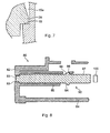
- FIG. 8 illustrates a pushbutton that is disclosed in JP 2010-225324A as an example of such an interior component.
- the pushbutton includes a button main body 80 and an indicator 90.
- An interior component according to the preamble of claim 1 is disclosed in the document Ep 2 154 699 .
- the button main body 80 includes an operation wall 82, which is exposed on the front side of the panel and is subjected to a pressing operation by a finger or the like, and a side wall 84, which extends rearward from a peripheral border of the operation wall 82.
- An indication window 83 is provided passing through the operation wall 82.
- An indicator holding wall 86 that is cylindrical in shape extends rearward from the circumference of this window 83.
- the indicator holding wall 86 includes, at appropriate positions, latch holes 88 that pass through the indicator holding wall 86 in its thickness direction.
- the indicator 90 is made from a material such as acrylic resin that is capable of guiding light, and held by the indicator holding wall 86.
- this indicator 90 includes an elongate indicator main body 92 and can be inserted into the indicator holding wall 86, an indicating portion 93 that projects further forward from the top surface of the indicator main body 92, and a pair of held projections 94 that project laterally from the posterior part of the side surface of the indicator main body 92.
- the indicating portion 93 has such a shape that it can be inserted from behind into the window 83 of the button main body 80, and in the state in which the indicating portion 93 is inserted into the window 83, the held projections 94 are fitted into the latch holes 88 of the indicator holding wall 86, so that the indicator 90 is fixed on the indicator holding wall 86.
- a light emitting element 100 for illumination is arranged that is mounted on a circuit board (not shown). Light that is emitted by the light emitting element 100 is guided to the indicating portion 93 through the indicator main body 92 of the indicator 90, thereby illuminating a particular area of the operation wall 82.
- JP 2010-225324 A is an example of related art.
- the indicator 90 is held only by inserting the indicating portion 93 into the indication window 83 and by fitting the held projections 94 into the latch holes 88 of the indicator holding wall 86. Therefore, the indicator 90 is liable to be shaken in the indicator holding wall 86. Such shaking may cause an abnormal noise, for example when the vehicle is driving. Further, in recent years, it has been proposed to mount the indicator on an outside surface of the component main body due to design requirements or the like. However, since in such a type of interior component, the indicator cannot be held in an enclosed manner as in the case using the indicator holding wall 86 illustrated in FIG. 8 , it becomes difficult to stably mount the indicator, and there is the risk that the indicator comes off.
- a vehicle interior component that includes a component main body and an indicator that is mounted thereon, the vehicle interior component enabling the component main body to reliably hold the indicator, and effectively preventing the indicator from being shaken, without making the configuration significantly more complex.
- the present invention provides a vehicle interior component including a component main body that includes an indicator holding portion; and an indicator that is made from a material capable of guiding light and has a shape that allows the indicator to be held by the indicator holding portion after being inserted into the indicator holding portion in a predetermined insertion direction.
- the indicator has a front side surface that faces forward in the insertion direction, and held projections that project further forward at a plurality of locations on the front side surface and are tapered.
- the indicator holding portion includes a front side holding portion that is made from a material into which the held projections can be stuck in the insertion direction and hold the held projections that are stuck thereinto, and a back side holding portion that restrains the indicator from behind, with respect to the insertion direction, at a position in which the held projections are stuck into the front side holding portions, preventing the held projections from disengaging from the front side holding portions.
- the component main body includes an indicating wall that is arranged so as to be exposed on the front side of an interior panel, and that has an indication window, the indicator holding portion is provided on the rear side of the indication window, extending from the rear surface of the indicating wall in a depth direction thereof, and has such a shape that the indicator is inserted into the indicator holding portion in the longitudinal direction of the indicator holding portion, and the indicator emits light toward the front side of the indicating wall through the indication window in the state in which the indicator is inserted into the indicator holding portion.
- the indicator includes: an indicator main body that has a shape that allows it to be inserted into the indicator holding portion from the rear side of the indicating wall and includes the front side surface, which faces the rear surface of the indicating wall; and an indicating portion that projects further forward in the insertion direction from the front side surface of the indicator main body and is shaped so as to be fitted into the indication window, and the held projections project from the front side surface at a plurality of locations surrounding the indicating portion, and are stuck into the rear surface of the indicating wall.
- the shapes of the indication window and the indicating portion can be set with a higher degree of freedom than, for example, an interior component in which an indicator is inserted into an indicator holding portion from the front side of the indicating wall. It is also possible to use the indicating wall as the front side holding portions into whose rear surfaces the held projections stick.
- the indication window is located at an end of the indicating wall
- the indicator holding portion includes: a holding wall that extends rearward from a location inward of the indication window; and restraining portions that protrude from an external side of the holding wall and are configured to restrain the indicator from both sides in a width direction of the indicator, which is a direction perpendicular to the insertion direction and perpendicular to the normal to the holding wall, so that the indicator can be inserted from the rear side of the indicating wall along the holding wall, the held projections of the indicator are located on both sides in the width direction of the indicator, the indicating portion being arranged between the held projections, and the back side holding portion is formed in the holding wall.
- the indicator is arranged at an end of the indicating wall on its rear side, in other words, outside the holding wall extending from the rear surface of the indicating wall, it is possible to stably hold the indicator by the holding wall, the restraining portions that project from the external sides of the holding wall, the held projections sticking into the rear surface of the indicating wall, and the back side holding portion restraining the indicator from behind.
- the indicator including the held projections be made from a material that has a higher Rockwell hardness than that of the front side holding portions. Held projections that are made from such a material can be stuck into the front side holding portions more reliably so as to be held by the front side holding portions.
- a vehicle interior component that includes a component main body and an indicator that is mounted thereon, the vehicle interior component enabling the component main body to reliably hold the indicator, and effectively preventing the indicator from being shaken, without making the configuration significantly more complex.
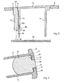
- a vehicle interior component according to this embodiment is a pushbutton that is incorporated into an interior panel 2 as illustrated in FIGS. 2 and 3 , and includes a button main body 10, which is a component main body, and an indicator 20.
- the present invention is not limited to such a pushbutton, and may also be applicable, for example, to a dial knob that is operated in a rotating manner or to a component that only functions to indicate but is not operated.
- the button main body 10 includes an indicating wall 12 and a peripheral wall 14.
- the indicating wall 12 is a wall that is arranged in a through hole 4 provided in an appropriate position in the interior panel 2 (see FIGS. 2 and 3 ) so as to be exposed on the front side, and an indication window 11 is provided on part of the indicating wall 12.
- the indicating wall 12 has a substantially rectangular shape, when seen from the front, and the indication window 11 is provided at an end in its longitudinal direction, the indication window 11 having a cut-out shape that is opened outward.
- the location of the indication window is not specifically limited, and the indication window may be, for example, a through hole that is provided in the middle of the indicating wall.
- the peripheral wall 14 extends rearward (downward in FIGS. 1 and 3 , and leftward in FIG. 4 ) from a location on the rear surface of the indicating wall 12 that is slightly inside the outer rim of the indicating wall 12, and has a shape of a substantially quadrangular prism as a whole.
- an outer peripheral portion of the indicating wall 12 has a portion that projects outward from the external sides of the peripheral wall 14, and the indication window 11 is provided in part of this outer peripheral portion.
- the button main body 10 is further provided with an indicator holding portion 16 for holding the indicator 20 on the rear side of the indication window 11 (the lower side in FIGS. 1 and 3 , and the left side in FIG. 4 ).
- the indicator holding portion 16 of this embodiment is configured to extend in the depth direction, that is, to the rear from the rear surface of the indicating wall 12, and to have such a shape that the indicator 20 is inserted into the indicator holding portion 16 in the longitudinal direction of the indicator holding portion 16 (that is, the depth direction) from the rear side of the indicating wall 12 (the lower side in FIGS. 1 and 3 , and the left side in FIG. 4 ).
- the specific configuration of the indicator holding portion 16 will be described later.
- the indicator 20 exhibits its indication function by emitting light toward the front side of the indicating wall 12 through the indication window 11.
- a circuit board 30 as illustrated in FIG. 3 is arranged on which a light emitting element 32, that is, a light source is mounted, and the entire indicator 20 is made from a material that has a light guiding functionality to be able to guide the light emitted by the light emitting element 32 towards the indication window 11.
- the indicator 20 includes an indicator main body 22, an indicating portion 24, and a pair of projections 26 that are to be held, as an integrated component.
- the indicator main body 22 is shaped so as to be inserted into the indicator holding portion 16 from the rear side of the indicating wall 12, and has a front side surface 21 that is located on the front side in its insertion direction, and faces the rear surface of the indicating wall 12. Further, both sides of the indicator main body 22 in the width direction of the indicator are recessed further inward than the other portions, and serve as restrained portions 23. These restrained portions 23 extend in a direction that is parallel to the insertion direction.
- the indicating portion 24 has a cross-section that is smaller than that of the front side surface 21 and has such a shape that it can be fitted into the indication window 11.
- the indicating portion 24 projects further forward in the insertion direction from an appropriate position of the front side surface 23.
- the indicating portion 24 is provided in the central portion of the indicator in its width direction.
- "Width direction of the indicator” refers here to a direction that is perpendicular to the insertion direction in which the indicator 20 is inserted into the indicator holding portion 16, and perpendicular to the normal to the holding wall 15 that will be described later.
- the indicating portion 24 emits the light that has been guided from the light emitting element 32 through the indicator main body 22 toward the front side (the upper side in FIGS. 1 and 3 , and the right side in FIG. 4 ) of the indicating wall 12.
- the held projections 26 are provided at a plurality of positions surrounding the indicating portion 24, that is, in this embodiment, positions on the both sides across the indicating portion 24 in the width direction of the indicator, and project forward from the front side surface 23.
- the held projections are tapered such that their cross-sectional area is reduced towards the tip.
- Tapered may refer to a shape that is sharpened to some extent that the held projections 26 can be stuck into the indicating wall 12 when they are pressed against the rear surface of the indicating wall 12 in the insertion direction. Within this extent, the tapered top may be slightly rounded.
- the shape of the held projection 26 is not limited to any specific shape and may be, for example, a cone as illustrated in FIG. 6(a) or a pyramid as illustrated in FIG. 6(b) .
- the indicator 20 is preferably made from a material that has the above-explained light guiding functionality, and a higher Rockwell hardness than that of the material from which the indicating wall 12 is made.
- the entire button main body 10 including the indicating wall 12 is made from polycarbonate, it is preferable that the indicator 20 be made from a methacrylate resin.
- the indicator holding portion 16 includes front side holding portions 13, a holding wall 15, and a pair of restraining portions 17 that project from the holding wall 15, the holding wall 15.
- a back side holding portion 18 is formed in the holding wall 15.
- the front side holding portions 13 are portions into which both held projections 26 of the indicator 20 inserted into the indicator holding portion 16 are stuck in the insertion direction, and that hold the projections 26 due to the held projections 26 being stuck into the front side holding portions 13.
- the portions of the indicating wall 12 that are located on both sides thereof across the indication window 11 in the width direction of the indicator correspond to the front side holding portions 13.
- the holding wall 15 is a wall that extends rearward from a location on the rear surface of the indicating wall 12 that is located directly inward of the indication window 11.
- the holding wall 15 is part of the peripheral wall 14 and located directly inward of the indication window 11 in the peripheral wall.
- each restraining portion 17 project from the external side of the holding wall 15 and extend in the insertion direction so as to guide the indicator 20 in the insertion direction while restraining it from the both sides in the width direction of the indicator, in other words, so as to let the indicator 20 move along the holding wall 15.
- the two restraining portions 17 of this embodiment are respectively shaped so as to embrace the two restrained portions 23 of the indicator 20.
- each restraining portion 17 includes, as an integrated component, a base wall 17a, which projects from the external side of the holding wall 15 in a direction normal thereto, and an embracing wall 17b, which projects inward from the base wall 17a in the width direction of the indicator.
- the embracing walls 17b restrain the restrained portions 23 of the indicator 20 from the side opposing the holding wall 15. This embracing wall 17b can be omitted if appropriate.
- the back side holding portion 18 is a portion that restrains, from behind, the back end portion (the lower end portion in FIGS. 1 and 3 ) of the indicator 20 that is inserted up to the point where the held projections 26 are stuck into the front side holding portions 13, preventing the held projections 26 from disengaging from the front side holding portions 13.
- the back side holding portion 18 is provided in the back end portion (the lower end portion in FIGS. 1 and 3 ) of the holding wall 15 and between the two restraining portions 17.
- a latching projection 28 projects on the holding wall 15 side from the inside surface of the indicator main body 22, that is, from the surface that faces the holding wall 15, on the other hand, a recess 15a into which the latching projection 28 can be fitted is provided on the outside surface of the holding wall 15.
- a step-like portion of the recess 15a that limits the lower end thereof corresponds to the back side holding portion 18.
- the part of the outside surface of the holding wall 15 that is located rearward with respect to the recess 15a is an inclined surface 19 that is receded further inward (rightward in FIG. 3 ) of the button main body 10 when following it to the rear end of the holding wall 15, so as to guide the latching projection 28 into the recess 15a.
- the insertion of the indicator 20 into the indicator holding portion 16 makes it easy to mount the indicator 20 on the button main body 10 and to reliably hold it, and prevents the indicator 20 from being shaken.
- the indicator 20 when the indicator 20 is inserted into a lower end opening (an opening enclosed by the holding wall 15 and two restraining portions 17) of the indicator holding portion 16 from the lower side (the rear side of the indicating wall 12), with the indicating portion 24 of the indicator 20 at the front, the indicator 20 advances in the insertion direction (in the direction towards the indicating wall 12) along the holding wall 15, while being restrained and guided by the two restraining portions 17, and ultimately reaches a position where the indicating portion 24 of the indicator 20 is fitted into the indication window 11 and the two held projections 26 abut against the rear surface of the front side holding portions 13 (the portions on both sides of the indication window 11) of the indicating wall 12.
- the indicator 20 When, from this position, the indicator 20 is further pushed in the insertion direction, the two held projections 26 are stuck into the front side holding portions 13, thereby being held by the front side holding portions 13.
- the latching projection 28 of the indicator 20 slides on the inclined surface 19 provided in the holding wall 15, and is fitted into the recess 15a at the position in which the two held projections 26 are stuck into the front side holding portions 13. Accordingly, the back side holding portion 18, which is a step-like portion that limits the lower end of the recess 15a, restrains the latching projection 28 from behind, preventing the held projections 26 from disengaging from the front side holding portions 13.
- the insertion direction in which the indicator 20 is inserted into the indicator holding portion 16 is not limited to the above-explained direction, that is, a direction from the rear side of the indicating wall 12 toward the indicating wall 12.
- a configuration is also possible in which the indicator is inserted into the indicator holding portion from the front side of the indicating wall through the indication window.
- the indicator can have, on its front side in the direction in which it is inserted, a front side surface and the held projections
- the indicator holding portion can include, on its front side in the insertion direction, the front side holding portions into which the held projections can be stuck.
- the entire indicator should have such a shape that it can be inserted into the indication window, that is, the indicator should have a cross-sectional area that is smaller than that of the indication window.
- the configuration in which the indicator 20 is inserted into the indicator holding portion 16 from the rear side of the indicating wall 12, as in this embodiment, has the advantage that it is possible to freely set the shapes of the indication window 11 and the indicating portion 24 that is fitted thereinto. There is a further advantage that it is possible to use part of the indicating wall 12 as the front side holding portions 13 into whose rear surfaces the held projections 26 are stuck.
- the location of the indication window 11 is not limited, and the location of the indicator holding portion 16 can be set according to the location of the indication window 11.
- the indication window is arranged in the central portion of the indicating wall, as in the configuration illustrated in FIG. 8 , it is possible to configure the indicator holding portion on the rear side of the indication window.
- the effect of the present invention is particularly remarkable when the indicator 20 is mounted at an end of the button main body 10, as in the foregoing embodiment.
- the indicator 20 is arranged at an end of the indicating wall 12 on its rear side, in other words, outside the holding wall 15 that extends from the rear surface of the indicating wall 12, it is possible to stably hold the indicator 20 by the combination of the holding wall 15, the restraining portions 17 that project from the external sides of the holding wall, the held projections 26 stuck into the rear surface of the front side holding portions 13 of the indicating wall 12, and the back side holding portion 18 restraining the indicator 20 from behind.
Landscapes
- Instrument Panels (AREA)
- Arrangements Of Lighting Devices For Vehicle Interiors, Mounting And Supporting Thereof, Circuits Therefore (AREA)
Claims (5)
- Fahrzeuginnenraumkomponente, welche aufweist:einen Komponentenhauptkörper (10), der einen Anzeigehalteabschnitt (16) umfasst; undeine Anzeige (20), die aus einem Material hergestellt ist, das zum Führen von Licht geeignet ist, und eine Form hat, die der Anzeige (20) erlaubt, mittels des Anzeigehalteabschnitts (16) gehalten zu werden, nachdem sie in den Anzeigehalteabschnitt (16) in einer vorgegebenen Einschubrichtung eingeschoben ist,wobei die Anzeige (20) eine Vorderseitenoberfläche (21), die nach vorne in Bezug auf die Einschubrichtung weist, und Haltevorsprünge aufweist, die an mehreren Orten an der Vorderseitenoberfläche (21) weiter nach vorne vorspringen,dadurch gekennzeichnet, dass sich die Haltevorsprünge verjüngen unddass der Anzeigehalteabschnitt (16) umfasst: einen Vorderseitenhalteabschnitt (13), der aus einem Material hergestellt ist, in das die Haltevorsprünge in einer Einschubrichtung stecken bleiben können und das die Haltevorsprünge hält, die darin stecken geblieben sind; undeinen Rückseitenhalteabschnitt (18), der die Anzeige (20) von hinten in Bezug auf die Einschubrichtung an einer Position begrenzt, in welcher die Haltevorsprünge in dem Vorderseitenhalteabschnitt (13) stecken geblieben sind, was die Haltevorsprünge daran hindert, sich von dem Vorderseitenhalteabschnitt (13) zu lösen.
- Fahrzeuginnenraumkomponente gemäß Anspruch 1,
wobei der Komponentenhauptkörper (10) eine Anzeigewand (12) umfasst, die eingerichtet ist, auf der Vorderseite einer Innenraumplatte exponiert zu sein, und die ein Anzeigefenster hat,
wobei der Anzeigehalteabschnitt (16) auf der Rückseite des Anzeigefensters angeordnet ist, sich von der hinteren Oberfläche der Anzeigewand (12) in einer Tiefenrichtung davon erstreckt und eine solche Form hat, das die Anzeige (20) in den Anzeigehalteabschnitt (16) in der longitudinalen Richtung des Anzeigehalteabschnitts (16) eingeschoben ist, und
wobei die Anzeige (20) eingerichtet ist, Licht in Richtung der Vorderseite der Anzeigewand (12) durch das Anzeigefenster in einem Zustand zu emittieren, in welchem die Anzeige (20) in den Anzeigehalteabschnitt (16) eingeschoben ist. - Fahrzeuginnenraumkomponente gemäß Anspruch 2,
wobei die Anzeige (20) umfasst: einen Anzeigehauptkörper (22), der eine Form hat, die ihm erlaubt, in den Anzeigehalteabschnitt (16) von der Rückseite der Anzeigewand (12) eingeschoben zu werden, und der die Vorderseitenoberfläche (21) umfasst, welche die hintere Oberfläche der Anzeigewand (12) gegenüberliegt; und einen Anzeigeabschnitt (24), der weiter nach vorne in der Einschubrichtung von der Vorderseitenoberfläche (21) des Anzeigehauptkörpers (22) vorspringt und geformt ist, um in das Anzeigefenster eingepasst zu werden, und
wobei die Haltevorsprünge von der Vorderseitenoberfläche (21) an einer Mehrzahl von Orten hervorspringen, die den Anzeigeabschnitt (21) umgeben, und in der hinteren Oberfläche der Anzeigewand (12) stecken geblieben sind. - Fahrzeuginnenraumkomponente gemäß Anspruch 3,
wobei das Anzeigefenster an einem Ende der Anzeigewand (12) lokalisiert ist,
wobei der Anzeigehalteabschnitt (16) umfasst: eine Haltewand (15), die sich nach hinten von einem Ort einwärts des Anzeigefensters erstreckt; und Begrenzungsabschnitte, die von einer äußeren Seite der Haltewand (15) hervorspringen und eingerichtet sind, die Anzeige (20) von beiden Seiten in einer Breitenrichtung der Anzeige (20) zu begrenzen, welche eine Richtung senkrecht zu der Einschubrichtung und senkrecht zu der Normalen der Haltewand (15) ist, so dass die Anzeige (20) von der Rückseite der Anzeigewand (12) entlang der Haltewand (15) eingeschoben werden kann,
wobei die Haltevorsprünge der Anzeige (20) auf beiden Seiten in der Breitenrichtung der Anzeige (20) lokalisiert sind, wobei der Anzeigeabschnitt (24) zwischen den Haltevorsprüngen angeordnet ist, und
wobei der Rückseitenhalteabschnitt (18) in der Haltewand (15) gebildet ist. - Fahrzeuginnenraumkomponente gemäß einem der Ansprüche 1 bis 4, wobei die Anzeige (20) einschließlich der Haltevorsprünge aus einem Material hergestellt ist, das eine höhere Rockwellhärte als die des Vorderseitenhalteabschnitts (13) aufweist.
Applications Claiming Priority (1)
| Application Number | Priority Date | Filing Date | Title |
|---|---|---|---|
| JP2012109550A JP5904004B2 (ja) | 2012-05-11 | 2012-05-11 | インジケータを有する車両用内装部品 |
Publications (2)
| Publication Number | Publication Date |
|---|---|
| EP2662876A1 EP2662876A1 (de) | 2013-11-13 |
| EP2662876B1 true EP2662876B1 (de) | 2014-12-31 |
Family
ID=47998219
Family Applications (1)
| Application Number | Title | Priority Date | Filing Date |
|---|---|---|---|
| EP20130160653 Not-in-force EP2662876B1 (de) | 2012-05-11 | 2013-03-22 | Fahrzeuginnenraumkomponente mit Anzeige |
Country Status (3)
| Country | Link |
|---|---|
| EP (1) | EP2662876B1 (de) |
| JP (1) | JP5904004B2 (de) |
| CN (1) | CN103390518B (de) |
Families Citing this family (2)
| Publication number | Priority date | Publication date | Assignee | Title |
|---|---|---|---|---|
| JP7514451B2 (ja) | 2019-05-23 | 2024-07-11 | 日本精機株式会社 | 表示装置 |
| CN110509771B (zh) * | 2019-09-18 | 2024-09-17 | 深圳嘉思铂科技有限公司 | 一种车载Android平台控制仪表盘及使用方法 |
Family Cites Families (11)
| Publication number | Priority date | Publication date | Assignee | Title |
|---|---|---|---|---|
| JPS6037127U (ja) * | 1983-08-22 | 1985-03-14 | 株式会社東海理化電機製作所 | 押圧操作部材用表示装置 |
| DE3533719A1 (de) * | 1985-09-21 | 1987-03-26 | Rheinmetall Gmbh | Schalteranordnung mit einer mehrzahl von bedienelementen |
| JP2552613Y2 (ja) * | 1990-06-01 | 1997-10-29 | 自動車電機工業株式会社 | 発光体付スイッチ |
| JPH09320381A (ja) * | 1996-05-29 | 1997-12-12 | Niles Parts Co Ltd | スイッチのノブ照明装置 |
| JP2001060424A (ja) * | 1999-08-23 | 2001-03-06 | Yazaki Corp | 操作ツマミの操作位置表示装置 |
| JP2001325848A (ja) * | 2000-05-17 | 2001-11-22 | Yuhshin Co Ltd | 車輌用コントロ−ルパネルに備えるスイッチ操作部 |
| JP4080322B2 (ja) * | 2002-12-24 | 2008-04-23 | アルプス電気株式会社 | 操作パネル装置の照光機構 |
| DE102004004247A1 (de) * | 2003-09-17 | 2005-05-25 | Prettlnoma Systems Gmbh | Tastenanordnung für eine Bedienblende |
| PL1523022T3 (pl) * | 2003-09-17 | 2012-04-30 | Pas Deutschland Gmbh | Układ przycisków do panelu obsługi |
| JP2010044972A (ja) * | 2008-08-14 | 2010-02-25 | Alps Electric Co Ltd | 照光式スイッチ装置 |
| JP5182524B2 (ja) | 2009-03-19 | 2013-04-17 | 住友電装株式会社 | 操作装置 |
-
2012
- 2012-05-11 JP JP2012109550A patent/JP5904004B2/ja not_active Expired - Fee Related
-
2013
- 2013-03-22 EP EP20130160653 patent/EP2662876B1/de not_active Not-in-force
- 2013-04-12 CN CN201310127598.6A patent/CN103390518B/zh not_active Expired - Fee Related
Also Published As
| Publication number | Publication date |
|---|---|
| EP2662876A1 (de) | 2013-11-13 |
| CN103390518A (zh) | 2013-11-13 |
| CN103390518B (zh) | 2015-08-19 |
| JP5904004B2 (ja) | 2016-04-13 |
| JP2013237284A (ja) | 2013-11-28 |
Similar Documents
| Publication | Publication Date | Title |
|---|---|---|
| US9659719B2 (en) | Display switch | |
| EP2662876B1 (de) | Fahrzeuginnenraumkomponente mit Anzeige | |
| US7530714B2 (en) | Front bezel with light-guiding device | |
| JP5182524B2 (ja) | 操作装置 | |
| US10035420B2 (en) | Vehicle instrument device | |
| US9711305B2 (en) | Multidirectional switch device | |
| US20120236570A1 (en) | Electronic apparatus | |
| US20180192744A1 (en) | Illuminated safety belt buckle for a safety belt device of a motor vehicle | |
| JP6177121B2 (ja) | 照明装置、及び収納装置 | |
| JP2008296781A (ja) | バンパー | |
| CN106057549B (zh) | 钮子开关以及开关装置 | |
| JP5201094B2 (ja) | 回転摘み | |
| JP5450035B2 (ja) | 車両用照明装置 | |
| JP2008147077A (ja) | 車載電子装置 | |
| JP4904829B2 (ja) | 発光表示構造 | |
| KR101704001B1 (ko) | 차량용 조명버튼 | |
| US20080232056A1 (en) | Front bezel with light-directing device | |
| JP2005209505A (ja) | 車載用押しボタンスイッチ | |
| JP6707840B2 (ja) | スイッチ装置 | |
| KR101557977B1 (ko) | 차량용 클러스터 | |
| JP6167977B2 (ja) | 照明装置 | |
| JP2007305349A (ja) | カバー付スイッチ及びスイッチ用カバー | |
| JP6133105B2 (ja) | 替芯ケース | |
| JP6133105B6 (ja) | 替芯ケース | |
| CN114866083A (zh) | 开关 |
Legal Events
| Date | Code | Title | Description |
|---|---|---|---|
| PUAI | Public reference made under article 153(3) epc to a published international application that has entered the european phase |
Free format text: ORIGINAL CODE: 0009012 |
|
| 17P | Request for examination filed |
Effective date: 20130827 |
|
| AK | Designated contracting states |
Kind code of ref document: A1 Designated state(s): AL AT BE BG CH CY CZ DE DK EE ES FI FR GB GR HR HU IE IS IT LI LT LU LV MC MK MT NL NO PL PT RO RS SE SI SK SM TR |
|
| AX | Request for extension of the european patent |
Extension state: BA ME |
|
| RIC1 | Information provided on ipc code assigned before grant |
Ipc: H01H 13/02 20060101AFI20140729BHEP |
|
| GRAP | Despatch of communication of intention to grant a patent |
Free format text: ORIGINAL CODE: EPIDOSNIGR1 |
|
| INTG | Intention to grant announced |
Effective date: 20140905 |
|
| GRAS | Grant fee paid |
Free format text: ORIGINAL CODE: EPIDOSNIGR3 |
|
| GRAA | (expected) grant |
Free format text: ORIGINAL CODE: 0009210 |
|
| AK | Designated contracting states |
Kind code of ref document: B1 Designated state(s): AL AT BE BG CH CY CZ DE DK EE ES FI FR GB GR HR HU IE IS IT LI LT LU LV MC MK MT NL NO PL PT RO RS SE SI SK SM TR |
|
| REG | Reference to a national code |
Ref country code: CH Ref legal event code: EP Ref country code: GB Ref legal event code: FG4D |
|
| REG | Reference to a national code |
Ref country code: IE Ref legal event code: FG4D |
|
| REG | Reference to a national code |
Ref country code: AT Ref legal event code: REF Ref document number: 704828 Country of ref document: AT Kind code of ref document: T Effective date: 20150215 |
|
| REG | Reference to a national code |
Ref country code: DE Ref legal event code: R096 Ref document number: 602013000724 Country of ref document: DE Effective date: 20150219 |
|
| PG25 | Lapsed in a contracting state [announced via postgrant information from national office to epo] |
Ref country code: LT Free format text: LAPSE BECAUSE OF FAILURE TO SUBMIT A TRANSLATION OF THE DESCRIPTION OR TO PAY THE FEE WITHIN THE PRESCRIBED TIME-LIMIT Effective date: 20141231 Ref country code: NO Free format text: LAPSE BECAUSE OF FAILURE TO SUBMIT A TRANSLATION OF THE DESCRIPTION OR TO PAY THE FEE WITHIN THE PRESCRIBED TIME-LIMIT Effective date: 20150331 Ref country code: FI Free format text: LAPSE BECAUSE OF FAILURE TO SUBMIT A TRANSLATION OF THE DESCRIPTION OR TO PAY THE FEE WITHIN THE PRESCRIBED TIME-LIMIT Effective date: 20141231 |
|
| REG | Reference to a national code |
Ref country code: NL Ref legal event code: VDEP Effective date: 20141231 |
|
| REG | Reference to a national code |
Ref country code: LT Ref legal event code: MG4D |
|
| PG25 | Lapsed in a contracting state [announced via postgrant information from national office to epo] |
Ref country code: RS Free format text: LAPSE BECAUSE OF FAILURE TO SUBMIT A TRANSLATION OF THE DESCRIPTION OR TO PAY THE FEE WITHIN THE PRESCRIBED TIME-LIMIT Effective date: 20141231 Ref country code: GR Free format text: LAPSE BECAUSE OF FAILURE TO SUBMIT A TRANSLATION OF THE DESCRIPTION OR TO PAY THE FEE WITHIN THE PRESCRIBED TIME-LIMIT Effective date: 20150401 Ref country code: HR Free format text: LAPSE BECAUSE OF FAILURE TO SUBMIT A TRANSLATION OF THE DESCRIPTION OR TO PAY THE FEE WITHIN THE PRESCRIBED TIME-LIMIT Effective date: 20141231 Ref country code: LV Free format text: LAPSE BECAUSE OF FAILURE TO SUBMIT A TRANSLATION OF THE DESCRIPTION OR TO PAY THE FEE WITHIN THE PRESCRIBED TIME-LIMIT Effective date: 20141231 Ref country code: SE Free format text: LAPSE BECAUSE OF FAILURE TO SUBMIT A TRANSLATION OF THE DESCRIPTION OR TO PAY THE FEE WITHIN THE PRESCRIBED TIME-LIMIT Effective date: 20141231 |
|
| REG | Reference to a national code |
Ref country code: AT Ref legal event code: MK05 Ref document number: 704828 Country of ref document: AT Kind code of ref document: T Effective date: 20141231 |
|
| PG25 | Lapsed in a contracting state [announced via postgrant information from national office to epo] |
Ref country code: NL Free format text: LAPSE BECAUSE OF FAILURE TO SUBMIT A TRANSLATION OF THE DESCRIPTION OR TO PAY THE FEE WITHIN THE PRESCRIBED TIME-LIMIT Effective date: 20141231 |
|
| PG25 | Lapsed in a contracting state [announced via postgrant information from national office to epo] |
Ref country code: RO Free format text: LAPSE BECAUSE OF FAILURE TO SUBMIT A TRANSLATION OF THE DESCRIPTION OR TO PAY THE FEE WITHIN THE PRESCRIBED TIME-LIMIT Effective date: 20141231 Ref country code: SK Free format text: LAPSE BECAUSE OF FAILURE TO SUBMIT A TRANSLATION OF THE DESCRIPTION OR TO PAY THE FEE WITHIN THE PRESCRIBED TIME-LIMIT Effective date: 20141231 Ref country code: ES Free format text: LAPSE BECAUSE OF FAILURE TO SUBMIT A TRANSLATION OF THE DESCRIPTION OR TO PAY THE FEE WITHIN THE PRESCRIBED TIME-LIMIT Effective date: 20141231 Ref country code: CZ Free format text: LAPSE BECAUSE OF FAILURE TO SUBMIT A TRANSLATION OF THE DESCRIPTION OR TO PAY THE FEE WITHIN THE PRESCRIBED TIME-LIMIT Effective date: 20141231 |
|
| PG25 | Lapsed in a contracting state [announced via postgrant information from national office to epo] |
Ref country code: IS Free format text: LAPSE BECAUSE OF FAILURE TO SUBMIT A TRANSLATION OF THE DESCRIPTION OR TO PAY THE FEE WITHIN THE PRESCRIBED TIME-LIMIT Effective date: 20150430 Ref country code: AT Free format text: LAPSE BECAUSE OF FAILURE TO SUBMIT A TRANSLATION OF THE DESCRIPTION OR TO PAY THE FEE WITHIN THE PRESCRIBED TIME-LIMIT Effective date: 20141231 Ref country code: PL Free format text: LAPSE BECAUSE OF FAILURE TO SUBMIT A TRANSLATION OF THE DESCRIPTION OR TO PAY THE FEE WITHIN THE PRESCRIBED TIME-LIMIT Effective date: 20141231 |
|
| REG | Reference to a national code |
Ref country code: DE Ref legal event code: R097 Ref document number: 602013000724 Country of ref document: DE |
|
| PG25 | Lapsed in a contracting state [announced via postgrant information from national office to epo] |
Ref country code: LU Free format text: LAPSE BECAUSE OF FAILURE TO SUBMIT A TRANSLATION OF THE DESCRIPTION OR TO PAY THE FEE WITHIN THE PRESCRIBED TIME-LIMIT Effective date: 20150322 Ref country code: DK Free format text: LAPSE BECAUSE OF FAILURE TO SUBMIT A TRANSLATION OF THE DESCRIPTION OR TO PAY THE FEE WITHIN THE PRESCRIBED TIME-LIMIT Effective date: 20141231 Ref country code: EE Free format text: LAPSE BECAUSE OF FAILURE TO SUBMIT A TRANSLATION OF THE DESCRIPTION OR TO PAY THE FEE WITHIN THE PRESCRIBED TIME-LIMIT Effective date: 20141231 Ref country code: MC Free format text: LAPSE BECAUSE OF FAILURE TO SUBMIT A TRANSLATION OF THE DESCRIPTION OR TO PAY THE FEE WITHIN THE PRESCRIBED TIME-LIMIT Effective date: 20141231 |
|
| PLBE | No opposition filed within time limit |
Free format text: ORIGINAL CODE: 0009261 |
|
| STAA | Information on the status of an ep patent application or granted ep patent |
Free format text: STATUS: NO OPPOSITION FILED WITHIN TIME LIMIT |
|
| 26N | No opposition filed |
Effective date: 20151001 |
|
| PG25 | Lapsed in a contracting state [announced via postgrant information from national office to epo] |
Ref country code: IT Free format text: LAPSE BECAUSE OF FAILURE TO SUBMIT A TRANSLATION OF THE DESCRIPTION OR TO PAY THE FEE WITHIN THE PRESCRIBED TIME-LIMIT Effective date: 20141231 |
|
| REG | Reference to a national code |
Ref country code: FR Ref legal event code: ST Effective date: 20151130 |
|
| REG | Reference to a national code |
Ref country code: IE Ref legal event code: MM4A |
|
| PG25 | Lapsed in a contracting state [announced via postgrant information from national office to epo] |
Ref country code: IE Free format text: LAPSE BECAUSE OF NON-PAYMENT OF DUE FEES Effective date: 20150322 |
|
| PG25 | Lapsed in a contracting state [announced via postgrant information from national office to epo] |
Ref country code: SI Free format text: LAPSE BECAUSE OF FAILURE TO SUBMIT A TRANSLATION OF THE DESCRIPTION OR TO PAY THE FEE WITHIN THE PRESCRIBED TIME-LIMIT Effective date: 20141231 Ref country code: FR Free format text: LAPSE BECAUSE OF NON-PAYMENT OF DUE FEES Effective date: 20150331 |
|
| PG25 | Lapsed in a contracting state [announced via postgrant information from national office to epo] |
Ref country code: BE Free format text: LAPSE BECAUSE OF FAILURE TO SUBMIT A TRANSLATION OF THE DESCRIPTION OR TO PAY THE FEE WITHIN THE PRESCRIBED TIME-LIMIT Effective date: 20141231 |
|
| REG | Reference to a national code |
Ref country code: CH Ref legal event code: PL |
|
| PG25 | Lapsed in a contracting state [announced via postgrant information from national office to epo] |
Ref country code: MT Free format text: LAPSE BECAUSE OF FAILURE TO SUBMIT A TRANSLATION OF THE DESCRIPTION OR TO PAY THE FEE WITHIN THE PRESCRIBED TIME-LIMIT Effective date: 20141231 |
|
| PG25 | Lapsed in a contracting state [announced via postgrant information from national office to epo] |
Ref country code: LI Free format text: LAPSE BECAUSE OF NON-PAYMENT OF DUE FEES Effective date: 20160331 Ref country code: CH Free format text: LAPSE BECAUSE OF NON-PAYMENT OF DUE FEES Effective date: 20160331 |
|
| PG25 | Lapsed in a contracting state [announced via postgrant information from national office to epo] |
Ref country code: HU Free format text: LAPSE BECAUSE OF FAILURE TO SUBMIT A TRANSLATION OF THE DESCRIPTION OR TO PAY THE FEE WITHIN THE PRESCRIBED TIME-LIMIT; INVALID AB INITIO Effective date: 20130322 Ref country code: BG Free format text: LAPSE BECAUSE OF FAILURE TO SUBMIT A TRANSLATION OF THE DESCRIPTION OR TO PAY THE FEE WITHIN THE PRESCRIBED TIME-LIMIT Effective date: 20141231 |
|
| PG25 | Lapsed in a contracting state [announced via postgrant information from national office to epo] |
Ref country code: CY Free format text: LAPSE BECAUSE OF FAILURE TO SUBMIT A TRANSLATION OF THE DESCRIPTION OR TO PAY THE FEE WITHIN THE PRESCRIBED TIME-LIMIT Effective date: 20141231 |
|
| PG25 | Lapsed in a contracting state [announced via postgrant information from national office to epo] |
Ref country code: TR Free format text: LAPSE BECAUSE OF FAILURE TO SUBMIT A TRANSLATION OF THE DESCRIPTION OR TO PAY THE FEE WITHIN THE PRESCRIBED TIME-LIMIT Effective date: 20141231 |
|
| GBPC | Gb: european patent ceased through non-payment of renewal fee |
Effective date: 20170322 |
|
| PG25 | Lapsed in a contracting state [announced via postgrant information from national office to epo] |
Ref country code: GB Free format text: LAPSE BECAUSE OF NON-PAYMENT OF DUE FEES Effective date: 20170322 |
|
| PG25 | Lapsed in a contracting state [announced via postgrant information from national office to epo] |
Ref country code: SM Free format text: LAPSE BECAUSE OF FAILURE TO SUBMIT A TRANSLATION OF THE DESCRIPTION OR TO PAY THE FEE WITHIN THE PRESCRIBED TIME-LIMIT Effective date: 20141231 |
|
| PG25 | Lapsed in a contracting state [announced via postgrant information from national office to epo] |
Ref country code: MK Free format text: LAPSE BECAUSE OF FAILURE TO SUBMIT A TRANSLATION OF THE DESCRIPTION OR TO PAY THE FEE WITHIN THE PRESCRIBED TIME-LIMIT Effective date: 20141231 |
|
| PG25 | Lapsed in a contracting state [announced via postgrant information from national office to epo] |
Ref country code: PT Free format text: LAPSE BECAUSE OF FAILURE TO SUBMIT A TRANSLATION OF THE DESCRIPTION OR TO PAY THE FEE WITHIN THE PRESCRIBED TIME-LIMIT Effective date: 20141231 |
|
| PG25 | Lapsed in a contracting state [announced via postgrant information from national office to epo] |
Ref country code: AL Free format text: LAPSE BECAUSE OF FAILURE TO SUBMIT A TRANSLATION OF THE DESCRIPTION OR TO PAY THE FEE WITHIN THE PRESCRIBED TIME-LIMIT Effective date: 20141231 |
|
| PGFP | Annual fee paid to national office [announced via postgrant information from national office to epo] |
Ref country code: DE Payment date: 20210310 Year of fee payment: 9 |
|
| REG | Reference to a national code |
Ref country code: DE Ref legal event code: R119 Ref document number: 602013000724 Country of ref document: DE |
|
| PG25 | Lapsed in a contracting state [announced via postgrant information from national office to epo] |
Ref country code: DE Free format text: LAPSE BECAUSE OF NON-PAYMENT OF DUE FEES Effective date: 20221001 |