EP2662523A1 - Trépan hélicoïdal pour vis sans fin d'un ensemble d'excavation du sol, en particulier pour la construction de pieux excavé et procédé de forage qui utilise un tel trépan - Google Patents
Trépan hélicoïdal pour vis sans fin d'un ensemble d'excavation du sol, en particulier pour la construction de pieux excavé et procédé de forage qui utilise un tel trépan Download PDFInfo
- Publication number
- EP2662523A1 EP2662523A1 EP13166540.8A EP13166540A EP2662523A1 EP 2662523 A1 EP2662523 A1 EP 2662523A1 EP 13166540 A EP13166540 A EP 13166540A EP 2662523 A1 EP2662523 A1 EP 2662523A1
- Authority
- EP
- European Patent Office
- Prior art keywords
- helical
- auger
- drill bit
- casing pipe
- longitudinal axis
- Prior art date
- Legal status (The legal status is an assumption and is not a legal conclusion. Google has not performed a legal analysis and makes no representation as to the accuracy of the status listed.)
- Granted
Links
- 238000009412 basement excavation Methods 0.000 title claims abstract description 96
- 238000005553 drilling Methods 0.000 title claims description 110
- 238000000034 method Methods 0.000 title claims description 26
- 238000005520 cutting process Methods 0.000 description 96
- YSSSPARMOAYJTE-UHFFFAOYSA-N dibenzo-18-crown-6 Chemical compound O1CCOCCOC2=CC=CC=C2OCCOCCOC2=CC=CC=C21 YSSSPARMOAYJTE-UHFFFAOYSA-N 0.000 description 81
- 208000014617 hemorrhoid Diseases 0.000 description 31
- 230000033001 locomotion Effects 0.000 description 17
- 230000008878 coupling Effects 0.000 description 11
- 238000010168 coupling process Methods 0.000 description 11
- 238000005859 coupling reaction Methods 0.000 description 11
- 238000006243 chemical reaction Methods 0.000 description 7
- 238000005192 partition Methods 0.000 description 7
- 230000005540 biological transmission Effects 0.000 description 6
- 230000002829 reductive effect Effects 0.000 description 6
- 230000009471 action Effects 0.000 description 5
- 230000004888 barrier function Effects 0.000 description 5
- 230000000694 effects Effects 0.000 description 5
- 230000036961 partial effect Effects 0.000 description 5
- 239000004568 cement Substances 0.000 description 4
- 230000035515 penetration Effects 0.000 description 4
- 238000005266 casting Methods 0.000 description 3
- 238000013461 design Methods 0.000 description 3
- 238000000605 extraction Methods 0.000 description 3
- 239000000463 material Substances 0.000 description 3
- 239000000203 mixture Substances 0.000 description 3
- 230000002787 reinforcement Effects 0.000 description 3
- PEDCQBHIVMGVHV-UHFFFAOYSA-N Glycerine Chemical compound OCC(O)CO PEDCQBHIVMGVHV-UHFFFAOYSA-N 0.000 description 2
- 230000001174 ascending effect Effects 0.000 description 2
- 238000010276 construction Methods 0.000 description 2
- 238000006073 displacement reaction Methods 0.000 description 2
- 238000005516 engineering process Methods 0.000 description 2
- 239000012530 fluid Substances 0.000 description 2
- 230000000670 limiting effect Effects 0.000 description 2
- 230000009467 reduction Effects 0.000 description 2
- 230000000630 rising effect Effects 0.000 description 2
- 238000004513 sizing Methods 0.000 description 2
- 230000036346 tooth eruption Effects 0.000 description 2
- 238000013519 translation Methods 0.000 description 2
- 238000003466 welding Methods 0.000 description 2
- 238000005452 bending Methods 0.000 description 1
- 230000000903 blocking effect Effects 0.000 description 1
- 230000003247 decreasing effect Effects 0.000 description 1
- 238000007599 discharging Methods 0.000 description 1
- 230000008030 elimination Effects 0.000 description 1
- 238000003379 elimination reaction Methods 0.000 description 1
- 230000002349 favourable effect Effects 0.000 description 1
- 239000006260 foam Substances 0.000 description 1
- 238000003780 insertion Methods 0.000 description 1
- 230000037431 insertion Effects 0.000 description 1
- 238000004519 manufacturing process Methods 0.000 description 1
- 239000007769 metal material Substances 0.000 description 1
- 230000000149 penetrating effect Effects 0.000 description 1
- 230000002093 peripheral effect Effects 0.000 description 1
- 238000012545 processing Methods 0.000 description 1
- 230000000750 progressive effect Effects 0.000 description 1
- 230000000284 resting effect Effects 0.000 description 1
- 239000004576 sand Substances 0.000 description 1
- 239000002689 soil Substances 0.000 description 1
- 230000001052 transient effect Effects 0.000 description 1
- XLYOFNOQVPJJNP-UHFFFAOYSA-N water Substances O XLYOFNOQVPJJNP-UHFFFAOYSA-N 0.000 description 1
Images


Classifications
-
- E—FIXED CONSTRUCTIONS
- E02—HYDRAULIC ENGINEERING; FOUNDATIONS; SOIL SHIFTING
- E02D—FOUNDATIONS; EXCAVATIONS; EMBANKMENTS; UNDERGROUND OR UNDERWATER STRUCTURES
- E02D7/00—Methods or apparatus for placing sheet pile bulkheads, piles, mouldpipes, or other moulds
- E02D7/28—Placing of hollow pipes or mould pipes by means arranged inside the piles or pipes
- E02D7/30—Placing of hollow pipes or mould pipes by means arranged inside the piles or pipes by driving cores
-
- E—FIXED CONSTRUCTIONS
- E21—EARTH DRILLING; MINING
- E21B—EARTH DRILLING, e.g. DEEP DRILLING; OBTAINING OIL, GAS, WATER, SOLUBLE OR MELTABLE MATERIALS OR A SLURRY OF MINERALS FROM WELLS
- E21B10/00—Drill bits
- E21B10/26—Drill bits with leading portion, i.e. drill bits with a pilot cutter; Drill bits for enlarging the borehole, e.g. reamers
-
- E—FIXED CONSTRUCTIONS
- E21—EARTH DRILLING; MINING
- E21B—EARTH DRILLING, e.g. DEEP DRILLING; OBTAINING OIL, GAS, WATER, SOLUBLE OR MELTABLE MATERIALS OR A SLURRY OF MINERALS FROM WELLS
- E21B10/00—Drill bits
- E21B10/44—Bits with helical conveying portion, e.g. screw type bits; Augers with leading portion or with detachable parts
-
- E—FIXED CONSTRUCTIONS
- E21—EARTH DRILLING; MINING
- E21B—EARTH DRILLING, e.g. DEEP DRILLING; OBTAINING OIL, GAS, WATER, SOLUBLE OR MELTABLE MATERIALS OR A SLURRY OF MINERALS FROM WELLS
- E21B17/00—Drilling rods or pipes; Flexible drill strings; Kellies; Drill collars; Sucker rods; Cables; Casings; Tubings
- E21B17/10—Wear protectors; Centralising devices, e.g. stabilisers
- E21B17/12—Devices for placing or drawing out wear protectors
-
- E—FIXED CONSTRUCTIONS
- E21—EARTH DRILLING; MINING
- E21B—EARTH DRILLING, e.g. DEEP DRILLING; OBTAINING OIL, GAS, WATER, SOLUBLE OR MELTABLE MATERIALS OR A SLURRY OF MINERALS FROM WELLS
- E21B7/00—Special methods or apparatus for drilling
- E21B7/003—Drilling with mechanical conveying means
- E21B7/005—Drilling with mechanical conveying means with helical conveying means
Definitions
- the present invention concerns a helical drill bit for an auger of a ground excavation assembly, in particular for building excavated piles, and a drilling method that uses such a bit.
- the present invention refers to a helical drill bit made according to the preamble of the attached claim 1, and to a drilling method carried out with the aforementioned helical drill bit.
- the present invention thus fits into the technological field of foundations in which, for almost twenty years, the technique of the so-called pile excavated with a continuous auger, partially or totally piped, has been known.
- pile excavated piles equipment is generally used that is adapted to carry out drilling or excavations having a substantially cylindrical shape with a vertical longitudinal axis, or having the desired inclination, relative to the surface of the ground (so-called "land surface") on which the piles are intended to be made.
- concrete is then cast that, by setting, forms the excavated piles that constitute the foundation structure for the subsequent work on top.
- the secondary piles (in turn identified with even numbers of the previous numbering, i.e. with 2, 4, 6, ...) are made by drilling adjacent, to the right and left respectively, to the primary piles (pile 2 adjacent to and interpenetrating with the primary piles 1 and 3, and so on), thus forming a substantially continuous partition or barrier.
- the correct penetration and the correct orientation, vertical or inclined, of all of these piles therefore work together to suitably make the excavated partition that, when filled with concrete according to what is known in the field, ensures an adequate support and impermeabilisation (when required) in the case of underground works or out-of-ground works.
- the equipment comprises a self-propelled machine 1 and a mast 2 supported and arranged in a direction that is substantially ascending and vertical with respect to the machine 1.
- the machine 1 has a carrying capacity suitable for supporting the mast 2 also during movement and it preferably comprises a cabin supported by a tracked structure (details not numbered) that allows it to move on the land surface.
- the mast 2 can advantageously move with respect to the machine 1, for example by means of a fluid actuator system, in particular one or more hydraulic cylinders (details not numbered), mounted between such a mast 2 and such a machine 1.
- the equipment can comprise an alignment system (details not numbered), for example an articulated parallelogram structure, suitable for keeping the mast 2 in the desired ascending direction with respect to the machine 1.
- the equipment illustrated in figure 1 also comprises a trolley 3 that is mobile along the mast 2, a lower drive head 4i and an upper drive head 4s both carried by the same trolley 3.
- the drive heads 4i, 4s are able to transform the power, typically of the hydraulic type, supplied by the machine 1 into the mechanical power (more specifically rotary and/or pushing and/or pulling) necessary to carry out the drilling or excavation by the actual excavation assembly of the equipment, which will be described hereafter.
- the drive heads are rotary tables 4i, 4s of the per sé known type (generally known by the name "rotary") suitable for setting in rotation and imparting the pulling and pushing movements on the aforementioned excavation assembly of the equipment.
- the equipment illustrated also comprises a guide member 5, for example of the hydraulic or manual type, which is mounted near to the base of the tower 2 and that is suitable for ensuring, in a per sé known way, that the appropriate orientation, vertical or inclined, of the excavation assembly is maintained.
- the guide member comprises an openable annular element 5 adapted to wrap around the excavation assembly so as to keep them in the appropriate orientation or "verticality" in the first metres of the drilling or excavation.
- annular element 5 can be opened at the suitable moment by the operator in the subsequent steps of the drilling operations.
- the equipment also comprises a sliding device 6 adapted to space from each other the drive heads 4i, 4s that are supported by the same trolley 3.
- the sliding device is a jack 6, connected, on one side, with the lower drive head 4i and, on the other side, with the upper drive head 4s, so as to take them away from or towards each other.
- the relative travel between the drive heads 4i, 4s is of the order of magnitude of a few tens of centimetres.
- the equipment comprises an axial movement system adapted to lift the load deriving from the assembly formed from the trolley 3, the drive heads 4i, 4s and the relative excavation assembly associated with them.
- the axial movement system of the drive heads comprises at least one hoisting winch 7 acting on the trolley 3 so as to move the latter through an appropriate traction winch including for example one or more cables and/or one or more ropes or other flexible traction elements that can be used for this purpose (for example chains, etc.).
- the axial movement system of the drive heads can also include a second traction rope, relayed towards the lower snub pulley 8 to exert a push on the trolley 3.
- the hoisting winch 7 can stay connected to a departing rope and a further winch (not shown) can be added to exert the push on the trolley 3.
- the hoisting winch 7 and/or the relay winch for pushing (and the snub pulley 8) are supported by the mast 2. Therefore, the lifting system fulfils the function of lifting, through traction, the aforementioned assembly and also performs the task of exerting a push on the aforementioned assembly so as to suitably drive the excavation assembly in the ground to allow it to be drilled.
- the equipment also includes an excavation assembly comprising an auger or drilling tool 9 typically shaped like an Archimedean screw or auger, henceforth called “auger” for the sake of simplicity.
- an auger 9 is supported and can be set in rotation by the upper drive head 4s.
- the aforementioned excavation assembly also comprises a substantially cylindrical casing pipe (also known as “guide pipe” and often defined as “casing") 10, coaxial with the auger 9, supported and able to be set in rotation by the lower drive head 4i and connected to it for the necessary pulling and pushing movements.
- the upper drive head 4s and the lower drive head 4i are thus adapted to control, independently from one another, the rotation of the auger 9 and of the casing pipe 10 about the respective longitudinal axes.
- the casing pipe 10 and the auger 9 are placed in counter-rotation to one another (in other words one of the two rotates about its longitudinal axis in a predetermined direction of rotation, whereas the other rotates simultaneously in the opposite direction of rotation).
- the rotation imparted on the auger 9 is directed in the clockwise direction, whereas the rotation imparted on the casing pipe is directed in the anti-clockwise direction.
- the trolley 3 is adapted to actuate the simultaneous sliding of the drilling tool 9 and of the casing pipe 10 along the mast 2.
- the presence of the single trolley 3 forces the auger 9 and the casing pipe 10 to carry out the drilling progressively and with a constant distance between the bit of the auger 9 and the cutting crown 18 installed beneath the casing pipe 10, apart from their possible relative displacement that can be controlled through the sliding device 6.
- the type of equipment shown in figure 1 or its variants are relatively simple and are able to make an excavation in which the depth of the drilling obtained through the penetration in the ground by the auger 9 and the casing pipe 10 (henceforth defined as “piped depth”) substantially corresponds to the depth of the hole obtained through the penetration in the ground by just the auger 9 (henceforth defined as “unpiped depth”).
- pipe depth substantially corresponds to the depth of the hole obtained through the penetration in the ground by just the auger 9
- the equipment illustrated in figure 2 includes a lower trolley 11i and an upper trolley 11s slidably mounted on the mast 2, and on which a lower or “intubating" drive head 12i, associated with the casing pipe 10 and an upper drive head 12s associated with the auger 9 are respectively mounted and supported.
- the trolleys 11i, 11s are thus operatively independent from each other and therefore each of them is able to exert an independent push or pull on the respective drive head 12i, 12s supported by it.
- both of the trolleys 11i, 11s slide along the same guides carried longitudinally by the mast 2 but spaced one from the other in an adjustable manner, manually or automatically (through a data processing unit, known commercially in the field as DMS - Drilling Mate System).
- the lifting system also comprises a pair of lifting devices 7, 14 capable of independently one from the other lifting and lowering (and/or pushing) the lower trolley 11i and the upper trolley 11s, respectively, thus adjusting the distance thereof. It is also provided for there to be a further service winch 13.
- the axial movement devices of the drive heads are winches 7, 14 possibly of the double-cable type (like the winch 7 shown in figure 2 ) mounted either on the rotary tower of the drilling machine 1 or directly on the mast 2 (as indicated in the figures).
- the "intubating" drive head 12i has an axial opening or inner passage, having an inner diameter such as to allow an auger element 9 to pass through it.
- the upper drive head 12s has an inner passage having an inner diameter that is compatible to allow the passage of an extension 15, known in the field as "tube” or "long tube".
- an extension element 15 mounted at the top of the auger 9 has an elongated substantially cylindrical shape, with outer diameter comparable to that of the trunk of the auger 9 (but not necessarily equal), and mechanical locking points that, when mechanically engaged by the drilling drive head 12s, allow the correct transmission of the drilling forces (torque, traction, thrust).
- said mechanical locking points can be longitudinal strips for the transmission by friction of the drilling forces or mixed systems with axial abutments for pulling and pushing and longitudinal strips for torque, developed at least locally near to the two extreme areas, lower and upper, which allow a mechanical abutment for the transmission of the forces between tube and upper drive head.
- the unpiped depth of the drilling can also extend significantly, for example for many metres, beneath the end part or excavation crown 18 of the casing pipe 10 (in other words beyond the so-called piped depth, the extension of which, on the other hand, remains substantially unchanged). Therefore, the excavated pile that is made with the help of the equipment illustrated in figure 2 has a greater length than the equipment illustrated in figure 1 .
- the overall structure of such equipment is in any case simpler and more effective than the variant described in figure 1 , having sliding devices 6 acting directly between tube and upper drive head (to limit the heights of such sliding devices that could otherwise be problematic in the case of restricted spaces or for transportation, it would be necessary to carry out many shorter travels and a multiplicity of grippings that would reduce its effectiveness and would complicate its control).
- the drilling obtained by using the equipment illustrated above, in particular also using that relative to figure 2 has two different diameters.
- the greater diameter corresponds to the outer diameter exhibited by the casing pipe 10, or more specifically to the cutting diameter of the crown 18 and it extends along the drilling in the piped section of depth, whereas the smaller diameter corresponds to the outer diameter exhibited by the bit of the auger defined by just the drilling tool 9 and it extends along the drilling in the unpiped section of depth.
- the difference between the greater diameter and the smaller diameter is of an order of magnitude of between about 50 mm and 120 mm (depending on the diameters) and the different shape of the drilling excavated with just the auger should be suitably considered at the design stage considering the actual load-bearing characteristics that the excavated pile obtained through the drilling itself must have.
- the casing pipe 10 has a tubular shape that extends around a longitudinal axis Z-Z and defines an internal axial cavity such as to allow the auger 9 to pass through it.
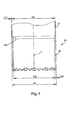
- the casing pipe 10 substantially comprises three sections or portions, in other words a coupling portion or half-joint 16, a jacket pipe 17, a cutting crown or shoe 18 located at the lower end of the casing pipe 10.
- the coupling portion or half-joint 16, the jacket pipe 17 and the cutting crown 18 are firmly connected together and act as a monolithic and integral element when the drilling equipment is operating; preferably, they are made from metallic material and, for example, they can be connected together through welding.
- the cutting crown 18 can be removably constrained with respect to the jacket pipe 17, through known fixing devices (screw, cable, key, ).
- the coupling portion or half-joint 16 is substantially hollow cylinder shaped, for example with a circular cross section, extending around the axis Z-Z.
- the half-joint 16 suitable for allowing the mechanical connection of the upper part of the casing pipe 10 with the "intubating" drive head 12i (or with intermediate jacket pipe elements, when the casing pipe consists of more than one jacket pipe, thus when there are at least two half-joints 16).
- the connection between the coupling portion or half-joint 16 with the "intubating" drive head 12i is provided so as to allow the optimal transmission of mechanical power to the casing pipe 10 to carry out the drilling (for example, by imparting a suitable torque and the pushing force).
- the coupling portion or half-joint 16 can also be adapted for removable connection with lower or bottom portions of possible further tubular elements that can be interposed between the "intubating" drive head 12i and the excavation crown 18 (details not shown).
- the coupling portion or half-joint 16 is equipped with connection means of the male type for the connection with the "intubating" drive head 12i.
- the mechanical connection between the coupling portion or half-joint 16 and the "intubating" drive head 12i can take place through one or more fixing systems that are per sé known in the field, for example keys, screws, bayonets and the like.
- the jacket pipe 17 has a substantially hollow cylindrical shape, for example with a circular cross section, extending around the longitudinal axis Z-Z.
- the jacket pipe 17 also has an inner diameter that is suitably sized so as to allow the auger 9 to pass axially through it.
- the jacket pipe 17 has a longitudinal or main axial extension with respect to the coupling portion or half-joint 16 and with respect to the cutting crown 18.
- the jacket pipe 17 is made so as to be sufficiently robust to transmit to the crown 18 the cutting actions for drilling: torque and thrust at the same time so as to be sufficiently light to not have an excessive impact on the stability of the drilling equipment during operation.
- the jacket pipe 17 can also be made with a double wall, in other words it can include an outer pipe and an inner pipe, in particular having walls of reduced thickness so that there is no presence of inner or outer steps in the jacket pipe 17, and therefore it takes up a configuration such as to ensure the continuity of the inner diameter and of the outer diameter passing from the cutting crown 18 to the jacket pipe 17 itself.
- the outer and inner diameter are similar and the advancing of the pipe in the excavated hole and that of the auger takes place without stranding.
- the cutting crown 18 has a substantially hollow cylindrical shape, for example with a circular cross section, extending around the longitudinal axis Z-Z. Moreover, the cutting crown 18 has an inner diameter that is sized so as to allow the auger 9 to pass axially beyond its terminal end. In this way, the drilling equipment is able to make the auger 9 operate also in sections of unpiped depth.
- the cutting crown 18 can also comprise cutting means (not numbered), in particular provided at the front, on the outside and/or inside with respect to its terminal end.
- the excavation assembly is able to extend the diameter of the drilling even beyond the outer diameter of the casing pipe 10, thus ensuring that the friction between ground and outer surface of the casing pipe 10 are low to allow the excavated pile to be made with lower stresses.
- the cutting crown 18 can have a height or axial extension of between about 500 mm and 2500 mm, whereas the diameters can vary indicatively from 300mm to 1500mm.
- the cylindrical wall of the cutting crown 18 has a thickness S18 generally comprised between about 20 mm and 60 mm.
- the thickness S18 is determined so that the cutting crown 18 is able to house the excavation teeth having the desired characteristics (for example, the diameter, the thickness and the type of teeth).
- the cutting crown 18 is generally the element that tends to wear out most often and therefore requires frequent restoration; also for this reason, the cutting crown 18 can also have a connection system with the jacket pipe 17 that is of the removable type, therefore different from the welding quoted earlier.
- the structure of the casing pipe 10 preferably involves the presence of an intermediate step 18a located between the cylindrical wall of the jacket pipe 17 and the cylindrical wall of the cutting crown 18.
- the step 18a is made between the inner part of the wall (narrower) of the jacket pipe 17 and the inner part of the walls (thicker) of the cutting crown 18, for example making a substantially frustoconical side surface that tapers in the direction of the terminal end of the cutting crown 18.
- the outer diameter D e of the casing pipe 10, preferably coinciding with the outer diameter of the jacket pipe 17 and of the cutting crown 18, is equal to about 40 inches, in other words about 1016 mm.
- the casing pipe 10 preferably has a single thickness and with an inner step 18a.
- the thickness S17 of the cylindrical wall of the jacket pipe 17 is comprised between about 8 mm and 15 mm.
- the inner diameter D i1 of the jacket pipe 17 is equal to 996mm (hypothesising a thickness S17 equal to 10mm).
- the cutting crown 18 has a thickness S18 equal for example to about 30 mm, and therefore the inner diameter D i2 of the crown 18 is about 956 mm (in other words it is about 60 mm less than the outer diameter).
- the cutting crown 18 has an inner diameter D i2 that is advantageously smaller than the inner diameter of the jacket pipe 17. This makes it possible to guide the auger 9 on a lower end section thus with greater precision in vertical orientation and allowing the reduction of the overall friction between auger 9 and casing pipe 10 in virtue of the presence of the inner step 18a.
- the auger 9 can have an outer diameter not greater than about 940 mm so that the auger 9 can pass freely, crossing the cutting crown 18 axially.
- the difference between the value of the outer diameter D e (about 1.016 mm) of the casing pipe 10 and the outer diameter (about 940 mm) of the auger 9 is about 76 mm.
- the aforementioned difference represents the difference in diameter in a drilling made by the equipment beyond the piped depth, which substantially corresponds to the difference in outer diameter (or "step") existing in the excavated pile made in the aforementioned drilling.
- the effects on the load-bearing capacity of each excavated pile due to the difference in diameter must be evaluated at the design stage also based on the shape and optimal configurations to be given to the reinforcement cages that can be inserted in the primary piles and/or in the secondary piles, on the amount of concrete to be cast, on the actual penetration in the ground of the intersecting piles in mutually adjacent positions up to a guaranteed depth.
- a barrier or a partition of intersecting piles is made through the equipment represented in figure 2 , we have an arrangement in which the piles located adjacent to one another have, at the unpiped depth, a smaller diameter (and therefore a greater mutual distance) by about 50-120mm with respect to the diameter that they have in the section of piped depth.
- the design choice of the distance between centres present between adjacent piles is greatly affected by this difference in diameters, as well as the precision of orientation or verticality of the drilling obtained.
- European patent application EP 0 974 729 to the same Applicant describes an excavation device sliding inside a casing pipe; such a device comprises a spiral-shaped auger welded around a tubular core.
- the auger ends at the bottom at a first horizontal plate to which it is fixedly attached and below which the tubular core extends defining a lower end portion.
- the lower end portion has a rotary unit fitted onto it, equipped with a cylindrical excavation bit and offset with respect to the central axis of the device.
- Such a rotary unit is provided with a second horizontal plate that comprises an abutment portion for the first horizontal plate.
- the auger and the tubular core begin to describe a combined movement of relative rotation between the plates and of translation downwards until the first plate goes into abutment with the abutment portion of the second plate, also pulling the rotary excavation unit into rotation as an enbloc with it.
- the excavation bit must be arranged outside the pipe.
- the excavation device described by the aforementioned European patent application does not allow excavation when the excavation bit is inside the casing pipe, because the excavation bit is counter-rotated and this movement opens a passage for discharging the cement. Therefore, this configuration inside the pipe can only be used for the casting step.
- a purpose of the present invention is to make a helical drill bit for an auger of a ground drilling assembly, in particular for building excavated piles, and a drilling method that uses such a bit, which are able to solve the aforementioned and other drawbacks of the prior art, and which at the same time can be made in a simple, safe, effective and cost-effective manner.
- this and other purposes are accomplished through a drilling tool bit according to the attached claim 1 and through a drilling method according to the attached claim 14.
- FIG 5 an example of drilling equipment including a drilling tool equipped with an example embodiment of a bit according to the present invention is illustrated. Such a tool is wholly indicated with 9' to distinguish it from the drilling tools illustrated in combination with the equipment of the previous figures and made according to the prior art.
- the drilling tool or auger 9' defines a helical or Archimedean screw-type structure extending cylindrically around a longitudinal axis X-X, for example defining circular-shaped spirals when observed in plan that are centred with respect to the longitudinal axis X-X, and it is supported and able to be actuated in thrust, traction and rotation, in a per sé known way, through the upper drive head 12s.
- the drilling tool 9' is adapted to be set in rotation by the drilling drive head 12s independently from the "intubating" drive head 12i that, on the other hand, controls the rotation of the casing pipe 10.
- the auger 9' is set in counter-rotation with respect to the direction of rotation of the casing pipe 10 (for a person observing from above the equipment illustrated in the drawings, the rotation imparted on the drilling tool 9' is generally directed in the clockwise direction, whereas the rotation imparted on the casing pipe 10 is usually directed in the anti-clockwise direction).
- the drilling tool 9' has a helical drill bit or auger bit 20 associated or associable, in particular positioned beneath, with a support portion 23 adapted to be connected with the drilling drive head 12s on the opposite side to the helical drill bit 20.
- the bit 20 and the support portion 23 extend mainly according to a longitudinal direction and at their periphery they define the aforementioned helical or Archimedean screw-type structure.
- the support portion 23 and the helical drill bit 20 are two distinct elements stably connected together, for example in a removable manner.
- the support portion 23 and the helical drill bit 20 can be made in a single piece, thus forming a monolithic auger 9'.
- the solution would be less expensive but the restoration manoeuvres of the helical drill bit 20 could be more difficult.
- the bit 20 has at least one lower helical end section 20i of the helical structure made peripherally by the auger 9'.
- the helical end section 20i is adapted to always remain fixedly connected to the support structure 23 and in particular to rotate about the longitudinal axis X-X of the auger 9' as a unit with the support structure 23, so as to make a drilling in the ground. Therefore, the helical drill bit 20 and all the parts of which it consists are fixedly connected and form a single body with the auger 9', and are such as to not have any relative movement with respect to each other, in particular that of rotation.
- the helical end section 20i extends around an extremity axis Y-Y that is offset with respect to the longitudinal axis X-X of the auger 9'.
- the extremity axis Y-Y is offset with respect to the longitudinal axis X-X.
- the extremity axis Y-Y is offset transversally (or radially), or spaced, with respect to the longitudinal axis X-X.
- Such an offsetting value between the axis X-X and the axis Y-Y is defined and remains constant in all working conditions.
- the extremity axis Y-Y is parallel, or eccentric, with respect to the longitudinal axis X-X.
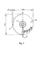
- the support portion 23 and the helical drill bit 20 comprise a supporting trunk or shaft 22 and, respectively, an excavation trunk or shaft 21 made with a hollow cylindrical, for example circular, shape and from the periphery of which the helical structure of the auger 9' extends peripherally.
- the helical end section 20i has a tapered helical extension, preferably substantially conical or frustoconical, with respect to an axis of extremity or of eccentricity Y-Y located eccentrically with respect to the longitudinal axis X-X.
- the longitudinal axis X-X coincides with the axis of the trunk 21 and/or 22.
- the extremity axis Y-Y is substantially parallel to the longitudinal axis X-X.
- the spirals defined by the helical end section 20i have a circular shape, in particular with progressively decreasing radial size, observed in plan with respect to the extremity axis Y-Y. Said spirals wrap around the extremity axis Y-Y for at least one quarter turn, preferably for a value comprised between one half turn and one turn.
- the aforementioned helical end section 20i could also have a cylindrical helical extension, but in this case the front cutting surface, coinciding with the lower transversal surface, should be substantially flat and not conical (concave or convex). In this case, the bit 20 would find it difficult to keep the excavation direction as straight as possible, due to the lack of said conical centring section.
- the size of the eccentricity of the axis Y-Y of the helical end section 20i of the auger 9' is indicated with reference letter "e".
- the helical end section 20i extends transversally with a protruding portion 25 thereof beyond the rest of the helical structure defined by the auger 9'.
- the helical end section 20i defined by the helical drill bit 20 is able to make a drilling having an actual diameter that is greater than that which can be obtained through the action of the other turns that are carried by the rest of the helical structure wholly defined by the auger 9' and that are generally concentric with the longitudinal axis X-X of the trunk 21 and/or 22.
- the protruding portion 25 extends for at least 180° of the helical extension defined by the helical end section 20i.
- the protruding portion 25 has a maximum protrusion at least equal to the size of the aforementioned eccentricity "e".
- the protruding portion 25 is made as a peripheral arched prominence, for example having the concavity facing radially outwards.
- the protruding portion 25 has a so-called “crescent moon” shape, the arched protrusion of which is gradually variable from a maximum value in a middle portion of the arc and equal to the eccentricity "e" up to a zero value at the ends of the arc diametrically opposite one another and located at about 90° from the positioning of the maximum protrusion.
- the helical end section 20i comprises at least one drill tooth 26 located at the protruding portion 25 so as to be able to extend radially even beyond the latter.
- the eccentricity "e” thus carries the drill tooth 26 at a distance from the longitudinal axis X-X such that it can excavate at a distance very close to the outer diameter of the casing pipe 10 and in particular even slightly greater and comparable to the excavation diameter made by the cutting crown 18 of such a casing pipe 10.
- the helical drill bit 20 has a smaller diameter size (for example equal to 940mm) than the diameter size of the casing pipe 10, such a bit 20 is able to make a drilling in which the diameter in the section of unpiped depth (obtained through the action of just the auger 9') corresponding to the diameter displayed in the section of piped depth (obtained through the action of the casing pipe 10 at its cutting crown 18).
- the helical end section 20i when observed in plan from above has a diameter ⁇ i equal to about 940 mm.
- the support portion 23 defines a proximal section of the helical structure of the auger 9'.
- the proximal section of the support portion 23 has a cylindrical extension centred around with respect the longitudinal axis X-X.
- such cylindrical extension has spirals having a circular shape when observed in plan with respect to the longitudinal axis X-X.
- the diameter defined by the proximal section is equal to the diameter ⁇ i of the eccentric helical part 20i, and its centre is located on the longitudinal axis X-X and coinciding with that of the trunk 22.
- the helical end section 20i can be made with a single-start screw or, preferably, with a double-start screw.
- a single-start screw the drilling operation is less preferred, even though it is simpler and more cost-effective, since it would not be effectively balanced; in fact, in this case the cutting stresses would be concentrated just on one side of the helical end section 20i, along the leading edge for drilling provided with teeth 26, those that carry out the enlargement beyond the natural diameter of a cylindrical helical drill bit, aligned with its own trunk.
- it is possible to generate lateral force components such as to make the entire helical structure deviate, making it vibrate or making it subject to bouncing when operating in particularly hard ground.
- the eccentricity "e" when it is required for the helical drill bit 20 to drill to the same cutting diameter as the crown 18, is substantially close to half the difference between the outer diameter D e of the casing pipe 10 (but more specifically of the outer diameter corresponding to the diameter cut by the teeth of the cutting crown 18) and the outer diameter of the circular cylindrical extension of the helical support structure defined overall by the auger 9'.
- a value that can be determined for the eccentricity "e” is close to about 38 mm (for example 40 mm).
- the value of the eccentricity "e” can be selected to be proportionally larger. Once the value of the eccentricity "e” has been assigned, it is kept constant during all of the operating and non-operating steps.
- the helical structure defined by the auger 9' additionally comprises an intermediate section 20s located in a proximal position with respect to the helical end section 20i. More specifically, the intermediate section 20s is located between the proximal section (belonging to the support portion 23) and the lower helical end section 20i.
- the intermediate section 20s has a helical extension substantially centred around the longitudinal axis X-X of the auger, coinciding with that of the trunk 21.
- the intermediate section 20s has a spiral defining a shape, when observed in plan with respect to the longitudinal axis X-X, that has a smaller size than the rest of the helical structure defined by the auger 9'.
- the aforementioned transversal shape of the intermediate section 20s does not extend transversally beyond the shape defined by the rest of the helical structure, but remains within the shape defined by its proximal section and its helical end section 20i.
- the choice of the diameter of the auger, in particular of the support portion 23, is made as a compromise between clearances and verticality.
- the intermediate section 20s is advantageous for the intermediate section 20s to be smaller than the value that has been preselected, in order to allow the helical drill bit 20 to easily pass through and its optimal positioning with axis of eccentricity Y-Y arranged in the operating excavation configuration at the maximum diameter, in the unpiped drilling section.
- the cylindrical extension with smaller size of the intermediate section 20s has a shape, when observed in plan with respect to the longitudinal axis X-X, that is quasi-circular, the centre of which lies in said longitudinal axis X-X, the diameter ⁇ s of which is the same as the diameter ⁇ i of the helical end section 20i but the periphery of which has an arched recess 24 curving in transversally with respect to the rest of the circumference defined by the centred helical part 20s.
- the arched recess 24 has its concavity facing radially outwards.
- the arched recess 24 extends for at least 180° of the helical extension defined by the intermediate section 20s.
- the arched recess 24 has a maximum inward curve at least equal to the size of the eccentricity "e" taken up by the helical end section 20i.
- the arched recess 24 substantially is shaped like a so-called “crescent moon", in which the inward curve of the arched recess is gradually variable from a maximum value in a middle portion of the arc and equal to the eccentricity up to a zero value at the ends of the arc diametrically opposite one another and arranged at about 90° with respect to said maximum value.
- the arched recess 24 of the intermediate section 20s can advantageously correspond to the arched protrusion 25 of the helical end section 20i made and located in a diametrically symmetrical manner with respect to the arched recess 24.
- such an arched protrusion 25 corresponds to the part of the circular cylindrical extension of the helical end section 20i that extends peripherally beyond the rest of the helical structure defined by the auger 9'.
- the shape, when observed in plan with respect to the axis X-X, of the intermediate section 20s is that of a curve consisting of a semi-circumference and a semi-ellipse the centres of which both lie on the longitudinal axis X-X and the diameter and respective greater axis of which coincide and both have the value equal to the diameter of the circumference of the helical end section 20i.
- the quasi-circular shape of the intermediate section 20s in plan from above has a greater dimension l max of about 940 mm (corresponding to the diameter of the semi-circumference coinciding with the greater axis of the semi-ellipse) and a smaller dimension l min (corresponding to the smaller axis of the semi-ellipse) of about 900 mm.
- the difference between l max and l min preferably differs by a value equal to the preselected value of the eccentricity "e".
- the characteristics thus described of the intermediate section 20s contribute to facilitating the passage of the helical end section 20i of the helical drill bit 20 through the cutting crown 18 of the casing pipe 10, which has a smaller inner diameter D i2 than the inner diameter D i1 of the jacket pipe 17, because it is used as a guide for the auger 9'.
- the aforementioned helical drill bit 20 has excellent applicability particularly in medium-hard and compacted ground, in which tamping cannot be applied.
- tamping cannot be applied.
- the tamping tool equipped with a shape having increasing cross section, against the walls of the hole preventing the excavated material from coming out transported by the helical structure defined by the drilling tool or auger (the tamping area is a portion of tool with cylindrical section of equal diameter with respect to the pipe).
- the drilling tool must be able to remove ground, at least partially and it is conveyed towards the land surface through the helical structure defined as a whole that has the function of a Archimedean screw.
- tamping tools could not be used since the adjacent primary piles, in a state of partial or total curing (concrete in set state) could not operate.
- the cutting crown 18 of the casing pipe 10 is sized in accordance with the configuration of the auger 9', in particular of the helical drill bit 20, in order to guide the helical structure defined by it during drilling.
- the radial distance between the cutting crown 18 and the auger 9' suitable for being set in mutual relative motion, must be reduced as much as possible, preserving the operating conditions of free relative sliding between the parts, which must take place as much as possible without stranding.
- a radial distance can vary from a few millimetres to a few tens of millimetres.
- the cutting crown 18 is designed to keep the helical structure wholly defined by the auger 9' guided on the casing pipe 10 itself.
- the auger 9' would be in continuous contact with the inner surface of the cutting crown 18 and wearing and stranding would be produced.
- the helical structure would not be precisely guided and the axis of the drilling going forward would be deviated with respect to the desired orientation or verticality that substantially coincides with the axis Z-Z of the casing pipe 10.
- the helical structure has an intermediate section 20s as described above.
- the shape with smaller size of the intermediate section 20s makes it possible, during the advancing of the helical drill bit 20 beyond the bottom of the casing pipe 10, for the helical end section 20i not to become stranded against the inner surface defined by the cutting crown 18.
- the axial extension of the intermediate section 20s can be substantially greater than the height H18 of the cutting crown 18.
- the cutting crown 18 preferably has a height H18 that is substantially greater than the pitch "p" of the proximal section (belonging to the support portion 23) of the helical structure defined by the auger 9', in this way confining at least the complete angular extension of 360°, of an entire turn, inside the cutting crown 18.
- a contact is made in at least three interface or contact points V, between such a proximal section defined by the support portion 23 and the inner surface defined by the cutting crown 18, obtaining a substantially balanced guide or support of the helical drill bit 20 keeping it in rotation around the longitudinal axis X-X.
- the auger 9' is guided on the cutting crown 18 for at least one complete turn (in other words 360°) of its spiral.
- the aforementioned contact points V can be considered as the points in which the resultant of the local contacts is applied, referring to a contact region limited to a relevant arc or sector.
- a tube 15 is installed on the auger 9', said tube being at least partially mounted above the upper drive head 12s and allowing the unpiped depth to be extended.
- the auger 9' itself could end at the top, and protrude beyond the upper drive head, with a section of auger, or with a section of auger having reduced size or furthermore with a simple elongated cylinder-shaped trunk (tube) that allows the piped depth to be increased through the "gripping" manoeuvre of the upper drive head.
- the upper drive head being axially mobile, can slide along the protruding upper section of the auger 9' or of the tube 15 (if separate) to grip said auger 9' or said tube 15 at an upper locking point in order to be able to increase the excavation depth by an extent equal to the travel carried out by the drive head.
- the simple relative sliding between the drive heads, or rather between the auger 9' and the casing pipe 10, like that which can be carried out in figure 1 is considered as a "gripping" manoeuvre.
- the intermediate section 20s can also have a shape, when observed in plan with respect to the axis X-X, having other shapes with respect to the one described above but with reduced size with respect to the helical end section 20i and to the proximal section.
- the intermediate section 20s can have a circular cylindrical extension with a smaller diameter than that of the support helical structure 22a.
- the helical drill bit 20 is axially fixed to the support portion 23 through coupling systems that transmit the excavation forces, for example through hexagonal grooved profiles that prevent relative rotations about the axis X-X ensuring the transmission of excavation torque, and through axial holding pins that prevent sliding along the axis X-X, ensuring the transmission of the extraction pull of the auger.
- the helical drill bit 20 is able to thus be fixed in a removable manner to different types of support portions 23 available on the market.
- the helical drill bit 20 defines a lower helical end section 20i of the helical structure defined by the auger 9'.
- the helical drill bit 20 includes the helical end section 20i and the intermediate section 20s, for example they are made in a single piece.
- an auger 9' the helical drill bit 20 of which comprises just the helical end section 20i, whereas the support portion 23 includes the proximal section and the intermediate section 20s.
- the helical drill bit 20 is made as a hollow core and in its end part has a union 27 adapted for the concrete to come out through it.
- the union 27 can be of any known type, for example a cap with chain, conical hatch with hinge, cylindrical hatch.
- the helical end section 20i in the lower central part has a helical drill bit, called central bit or pilot bit 28, known in the field, generally of the dismountable and replaceable type, in which at least one cutting tooth carries out the excavation beneath the trunk 21.
- Said tooth is positioned on the central part (as indicated in figure 9 ) or it can be mounted on the periphery of the trunk 21, with the cutting end towards the inside (not represented).
- the helical drill bit 20 at its distal portion comprises a pilot bit 28, for example extending in a prevalently axial direction.
- the pilot bit 28 tends to keep the drilling substantially aligned with the longitudinal axis X-X.
- the pilot bit 28 carries out a cylindrical excavation having a greater transversal extension with respect to its own transversal dimensions. This condition remains until the helical drill bit 20 is contained inside the casing pipe 10 during piped drilling.
- the pilot bit 28 is designed to excavate simultaneously at the front (downwards) and at the side (for eccentric excavation) when it operates on the ground to be excavated in the space circumscribed by the casing pipe 10, and in particular on the cutting crown 18.
- the longitudinal axis X-X in operation tends to deviate from the desired orientation and substantially coinciding with the axis Z-Z of the casing pipe 10 during piped drilling; in particular, during the rotation of the auger 9', when the helical drill bit 20 is in a retracted position with respect to the cutting crown 18, the auger 9' with its helical drill bit 20 has a deviation at the bottom equal to at least the value of the eccentricity "e". Consequently, the central bit 28 tends in this step to describe a circumference C of radius equal to the eccentricity "e”.
- the axes Z-Z and Y-Y coincide only near to the pilot bit 28.
- the longitudinal axis X-X in at least this excavation configuration, on the other hand, takes up a deviated configuration, since it is kept centred at the top (coinciding with the axis Z-Z of the upper drive head 12s) whereas at the base, near to the pilot bit 28, it is laterally deviated by a value at least equal to the eccentricity "e".
- the overall helical structure of the auger 9' and the casing pipe 10 as a function of the eccentricity "e" taken on by the helical drill bit 20, for example taking into consideration one or more of the following factors: rigidity and clearances that can be accumulated in relation to the overall helical structure, clearances on the drive heads 12i, 12s and on the respective trolleys 11i, 11s with respect to the tower 2, constructability of the helical drill bit 20, internal dimensions of the cutting crown 18, axial extension of the cutting crown 18, axial extension of the helical drill bit 20, construction diameters of the helical drill bit 20.
- This sizing leads to having a combination between the helical structure overall defined by the auger 9' and the casing pipe 10 such as to allow drilling in optimal conditions and with reduced consumption of the mutually moving parts due to relative sliding, to the elimination of joints and stranding during the relative translation, thus increasing the useful life of the helical drill bit 20 for greater efficiency, also ensuring that the maximum excavation diameter is maintained for the entire unpiped depth.
- the helical drill bit 20 when the helical drill bit 20 is positioned axially in an intermediate configuration in which the lower helical end section 20i is beyond the cutting crown 18 whereas the intermediate section 20s is still partially engaged inside the cutting crown 18, the helical drill bit 20 can begin to take up its natural excavation position, keeping the axis X-X aligned with the axis Z-Z of the casing pipe.
- the pilot bit 28 (represented in a different variant from the previous ones) will tend to centre in the hole made by itself, which is concentric to the axis Z-Z of the casing pipe 10.
- the axis X-X of the auger 9' becomes fixed and it no longer excavates laterally (i.e. it no longer describes a circular trajectory C concentric to the axis Z-Z of the casing pipe 10).
- the rotation axis of the helical drill bit 20, and more generally the axis X-X of the auger 9' is no longer deviated but coincides with that of the hole being made, i.e. relating to unpiped drilling.
- the eccentric part is represented by the helical end section 20i from which the excavation teeth 26 protrude, positioned on the protruding portion 25, which ensure the over-excavation "s" with greater diameter with respect to that of the remaining helical structure; in particular, such a greater diameter is substantially equal to that made by the cutting crown 18 of the casing pipe 10.
- the excavation teeth 26, are positioned along the outer periphery of the helical plane with conical extension.
- the helical drill bit 20 In this transient step, in which the helical drill bit 20 goes completely beyond the cutting crown 18, the helical drill bit 20 itself is guided in a not yet perfect manner because, if the support portion 23 is present in the form with smaller size, it does not allow a perfect centring on the inner walls of the cutting crown 18.
- at least one pair of points, or rather a pair of portions are in any case in contact: at least one first contact is present between the intermediate section 20s and the crown 18 and a second is present between the support portion 23 (auger that reaches the top in connection with the upper drive head 12s) and the crown 18.
- Such contacts in any case guide the helical drill bit 20, but preferably the guided support ensured by the support portion 23 with at least 2 or 3 contact points is certainly more precise and effective in keeping the longitudinal axis Z-Z and that of the auger X-X coaxial.
- the pilot bit 28 can protrude more or less and have various shapes, also asymmetrical, indicated in the figures with reference numeral 28' (pilot bit end), all in any case intended to centre the helical drill bit 20 on the desired drilling axis ( figure 11 ) or even to push ( figure 12 ) the helical end section 20i against the wall of the drilling being made.
- reference numeral 28' pilot bit end
- the helical drill bit 20 has the helical end section 20i made like an eccentric portion, it will cut in the most protruding part, i.e. that in the direction of the eccentricity.
- the helical drill bit 20 will be pushed inwards - in other words towards the axis X-X - exerting a natural radial stress that leads to a reduction of its actual eccentricity value, and thus of its ability to excavate a greater diameter.
- Such an effect can also be counteracted by the shape of the selected pilot bit 28, for example in the region close to the helical end section 20i, and in greater detail in the area that goes from the pilot bit 28 to the eccentric part of maximum bulk, indicated with rp (reaction section of the bit) of the helical end section 20i.
- the helical drill bit 20 works at least partially inserted in the casing pipe 10 (retracted position) it is the cutting crown 18 that cuts the portion of ground necessary to carry out the drilling suitable for making the excavated pile and the helical drill bit 20 located inside only has the function of demolishing the central core of ground.
- the helical drill bit 20 when the helical drill bit 20 is in advanced position like in the case of figures 11 and 12 , it excavates the portion of ground, and therefore the teeth indicated with 26 and all the other teeth positioned along the cutting line of the lower section 20i (or two cutting lines in the case of double-start screws) on the lower portion of bit are shaped so as to cut the central part and ensure, also through an elongated shape, a favourable lateral containment guide in contrast with the reaction thrusts of the ground that act on the eccentric part of the helical structure defined by the auger 9'. Moreover, the helical structure itself of the auger 9' is developed angularly so as to counteract the eccentric thrusts of the cutting and allow a support on a region opposite that of the helical end section 20i.
- a particularly advantageous configuration of the excavation teeth 26 is that through which a regular passage of the helical drill bit 20 through the cutting crown 18 is obtained, with which efficiency is guaranteed in the eccentric excavation.
- the helical end section 20i can define a helical structure of the single-start screw or double-start screw type.
- the pitch of the helical structure defined by the helical drill bit 20 is advantageously equal to that of the helical structure of the proximal section made by the support portion 23, so as to not have variations in section that can produce problems for the evacuation of the ground.
- the second auger opposite the first does not necessarily extend for the entire axial extension of the helical drill bit 20, but only in a lower region of such a helical drill bit 20.
- the pitch between the start screws is reduced with respect to that of the helical structure made by the proximal section belonging to the support portion 23.
- the presence of a further opposite start screw also contributes to balancing the transversal thrusts and supporting the bit against such thrusts during the cutting produced by the eccentric element rp.
- the arrangement of the teeth 26 can be such as to give them a configuration so that during cutting a force is generated that has a transversal component oriented towards the eccentric part of the bit 20, so as to counteract the thrusts of the ground and promote keeping the bit 20 in the position of maximum drilling diameter.
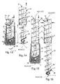
- the helical drill bit 20 is pushed in the excavation at the same time as the casing pipe 10, including the jacket pipe 17 and the cutting crown 18. In this condition the helical drill bit 20 is slightly retracted with respect to the bottom crown of the casing pipe (level indicated with H).
- the cutting crown 18 excavates the ground cutting the maximum diameter and the helical drill bit 20 has the function of merely breaking up the cylindrical column of ground and produces its evacuation. Indeed, the excavated ground is progressively conveyed towards the surface through the overall helical structure of the auger 9'.
- the inner surface defined by the walls of the cutting crown 18, narrower than that defined by the walls of the jacket pipe 17, is in contact with the turns of the helical structure defined by the helical end section 20i of the helical drill bit 20.
- the helical end section 20i tends to deviate the eccentric turns so as to align their centre (and therefore the eccentric axis Y-Y) with the longitudinal axis Z-Z defined by the cutting crown 18 itself, in the portion located lower down of the casing pipe 10. Consequently, as stated above, the axis X-X of the helical drill bit 20, near to the cutting crown 18 in this step describes a circular trajectory C having a radius equal to about the value of the eccentricity "e" exhibited by the eccentric helical portion 20i.
- the movement of the helical structure defined by the helical end section 20i of the helical drill bit 20 that occurs near to the pilot bit 28, generates forces capable of facilitating the breaking up of the ground, making its subsequent evacuation easy.
- the pilot bit 28 is able to make an excavation imprint indicated with 29 that is greater than the actual diameter of the pilot bit 28 and that in any case has a conical, or at least convex, shape in longitudinal section. This step can go on until the "intubating" drive head 12i to which the casing pipe 10 is connected reaches the lower end stroke, corresponding to the maximum excavation depth of the casing pipe 10 (piped depth).
- just the casing pipe 10 is preferably lifted by a height at least equal to or greater than the axial extension, indicated with W, of the bit 20 (normally about 2-3 m) so as to carry the entire helical drill bit 20 below the casing pipe 10 (and the cutting crown 18).
- W the axial extension
- the helical structure of the proximal section 23 of the auger 9' guides the rotation of the helical drill bit 20, centring it.
- the auger 9' continues to be rotated in accordance with the previous step, whereas the casing pipe 10 is advantageously kept in counter-rotation with respect to the auger 9', to avoid the occurrence of high external friction with the ground that would cause the potential blocking of the auger 9' in drilling in the operating step.
- the helical structure wholly defined by the auger 9' is pushed (using the suitable motor means if its weight is not sufficient) against the bottom of the drilling being made so as to force the pilot bit 28 to take up a position centred in the excavation imprint 29 made by it in the step shown in figure 13 .
- the longitudinal axis Z-Z of the casing pipe 10 and the longitudinal axis XX of the auger 9' coincide.
- the casing pipe 10 progressively lowers with the auger 9', until it goes back into the position taken up at the end of the step represented in figure 13 .
- the helical drill bit 20 is able to proceed with drilling below the casing pipe 10, remaining in an advanced position, for the relevant section at the unpiped depth by virtue of the possibility of relative axial movement between the auger 9' and casing pipe 10.
- the helical drill bit 20 is advantageously guided and centred in at least one location positioned near to the inner surface of the cutting crown 18. This ensures the guiding through the contact with the turns of the helical structure defined by the proximal section 23 again at the at least three points (or three sector arcs), indicated with V.
- the drilling drive head 12s is released from the auger 9' and the pipe extension 15 is connected to the top of the helical structure.
- the tube can also be made as an extension of the support portion 23.
- the drilling drive head 12s is made to rise along the mast 2, until it is locked at the top of the tube 15. In this way, it is possible to have an excavation extension equal to the travel carried out by the drive head between the original position and that arranged at a higher level.
- the tube it is possible for the tube to have intermediate locking points and in this case the drive head 20s can lock on them without directly reaching the farthest one arranged at the top (shorter travels of the drive head are thus required, but it is necessary to carry out more "grips").
- the filling of the excavation at the end of drilling is carried out with concrete or cement mixture that is poured or pumped through the hollow inner core of the helical structure 21a, when the auger 9' and the casing pipe are both going up. From this point on the excavated pile is finished off, with relative application of a reinforcement cage, when provided, which is widely known in the field.
- the helical drill bit 20 is brought outside of the cutting crown 18 (in advanced position) in an intermediate step between the initial step and that corresponding to the drilling of the maximum piped depth.
- the helical drill bit 20 from the outset starts in advanced position with respect to the crown 18.
- the piped depth will be shorter, for a level substantially equal to the height of the helical drill bit 20.
- the helical drill bit 20 never has to work inside the crown 18, a step in which it is required for it to break up the ground, and it can always work outside of it.
- the pilot bit 28 can also be selected so as to take up a significant axial extension so as to act as a centring element to best contain the transversal thrusts that develop during the eccentric excavation carried out by the helical end section 20i of the helical drill bit 20.
- a pilot hole directed vertically and with an equivalent diameter to that of the pilot bit 28, can be preliminarily made with directed drilling techniques and if required, when the ground is very compacted or when there are rocky layers, advantageously formed using water or air-operated down-the-hole hammers, head hammers or vibrating-rotating systems.
- the drilling of the helical drill bit 20 can begin by slotting the pilot bit 28 in the aforementioned pilot hole.
- the directed pilot hole (possibly filled with light filling materials like foams, sand, mixtures, ...) acts as a further guide for the helical drill bit 20 that will advance resting and guided in two different locations, the first at the base of the pilot bit 28 and the second at the interface between the proximal section 23 of the helical structure and the inner surface of the cutting crown 18.
- the drilling will therefore proceed with the maximum guarantee of keeping the desired maximum diameter obtained thanks to the helical drill bit 20, which can advantageously be equal to the diameter that can be obtained through the cutting action of the crown 18.
- a further variant provides not simultaneously extracting the casing pipe 10 and the auger 9' in the casting step, but leaving the casing pipe 10 in the drilling (perhaps keeping it in rotation), extracting just the auger 9' defining the overall helical structure. In this way, the helical drill bit 20 will be extracted passing through the cutting crown 18 and at that moment making the overall helical structure take up a deviated configuration.
- the same machine 1 or another one without distinction can be set up with just the auger 9' equipped at its end with at least one lower helical end section 20i and alternatively with an intermediate section 20s or with a support portion 23 or even with both, until a length is reached such as to allow excavation below the casing pipe 10.
- the same auger 9' could be sufficiently long to reach the maximum unpiped depth required or it could be equipped with a tube 15 to extend its excavation lengths.
- the machine can continue feeding the excavation beyond the piped drilling, continuing at least to rotate or to push if necessary, until the required level is reached.
- the same machine could hook the pipe again to be able to move it axially with respect to the auger 9' or to put it in counter-rotation in order to reduce its frictions.
- a further variant of this device is represented by a helical drill bit 20 equipped with a protruding portion that is significantly longer than the diametral bulk of the casing pipe 10.
- the excavation diameter of the bit 20 can be substantially greater than that excavated by the cutting crown 18. In this condition, it is possible to make excavations at the base of the pile (corresponding to the piped portion) with enlarged diameter, thus with a bulb capable of increasing the load-bearing capacity of the pile.
- a further embodiment of a helical drill bit 20 is shown.
- Such a helical drill bit 20 is equipped with an extremity axis ⁇ - ⁇ that is also misaligned with respect to the longitudinal axis X-X.
- the extremity axis ⁇ - ⁇ is offset with respect to the longitudinal axis X-X.
- the extremity axis ⁇ - ⁇ is inclined, in other words it is angularly offset, by an angle ⁇ with respect to the longitudinal axis X-X of the support portion 23 and thus of a main part of the auger 9'.
- the angle ⁇ thus defines an "angular eccentricity" (substantially equivalent to the so-called “transversal or radial eccentricity” indicated with “e” in the embodiment of the bit 20 illustrated in the previous figures) that the helical end section 20i takes up with respect to the rest of the helical structure defined by the auger 9'.
- the extremity axis ⁇ - ⁇ is incident with the longitudinal axis X-X.
- the angle ⁇ is less than 5°, in particular in the illustrated embodiment it is equal to about 2°.
- the inclination of mounting of the trunk 22 with respect to the axis of the trunk 21, ensures that the cutting teeth of the helical drill bit can be projected radially, when the helical drill bit 20 is advancing with respect to the casing pipe 10, to excavate at a diameter that is advantageously equal to the cutting diameter of the excavation crown 18.
- the auger 9' When the helical drill bit 20 is confined inside the casing pipe 10 ( figure 18 ), the auger 9' will be arranged in a deviated configuration so as to allow the lower helical end section 20i, with inclined axis ⁇ - ⁇ to be housed inside the excavation crown 18.
- the longitudinal axis X-X like in the previous cases, will therefore be arranged in a deviated configuration, since on the top it is kept centred by the upper drive head 12s, whereas at the bottom, near to the helical drill bit 20, it will be moved by a similar extent as the value of the eccentricity.
- the cutting teeth 26 that are positioned on the protruding region 25 are capable of cutting the over-excavation "s" beneath the casing pipe 10, thus being able to allow drilling of diameter advantageously equal to that of the cutting crown 18.
- both of the embodiments of the bit 20 and the relative drilling method according to the present invention can also be used in an embodiment of equipment as shown in figure 1 , especially in the version with sliding devices 6 connected between upper drive head 4s and auger 9.
- helical drill bit 20 the helical end section 20i of which has the respective extremity axis equipped with a transversal offset (or distance) and simultaneously with an angular offset (or inclination) with respect to the longitudinal axis X-X.
- the extremity axis would assume both a so-called “transversal eccentricity” (or radial) indicated with “e” and an “angular eccentricity” indicated with “ ⁇ ”, and it would therefore be oriented in space in a substantially skew manner with respect to the longitudinal axis X-X.
- transversal eccentricity or radial
- ⁇ angular eccentricity
Applications Claiming Priority (1)
| Application Number | Priority Date | Filing Date | Title |
|---|---|---|---|
| IT000405A ITTO20120405A1 (it) | 2012-05-07 | 2012-05-07 | Punta di scavo per un'elica di un assieme di scavo di terreno, in particolare per la realizzazione di pali escavati, e procedimento di perforazione che utilizza tale punta. |
Publications (2)
| Publication Number | Publication Date |
|---|---|
| EP2662523A1 true EP2662523A1 (fr) | 2013-11-13 |
| EP2662523B1 EP2662523B1 (fr) | 2016-06-29 |
Family
ID=46397520
Family Applications (1)
| Application Number | Title | Priority Date | Filing Date |
|---|---|---|---|
| EP13166540.8A Active EP2662523B1 (fr) | 2012-05-07 | 2013-05-03 | Trépan hélicoïdal pour vis sans fin d'un ensemble d'excavation du sol, en particulier pour la construction de pieux excavé et procédé de forage qui utilise un tel trépan |
Country Status (5)
| Country | Link |
|---|---|
| US (1) | US9157209B2 (fr) |
| EP (1) | EP2662523B1 (fr) |
| AU (1) | AU2013204232B2 (fr) |
| CA (1) | CA2814917C (fr) |
| IT (1) | ITTO20120405A1 (fr) |
Cited By (10)
| Publication number | Priority date | Publication date | Assignee | Title |
|---|---|---|---|---|
| BE1022352B1 (nl) * | 2015-01-07 | 2016-03-16 | Jde Funderingstechniek Bvba | Boorvoorziening en werkwijze voor het selectief vervaardigen van funderingspalen door gronduithaling of grondverdringing |
| EP3081737A3 (fr) * | 2015-04-17 | 2016-11-02 | BAUER Maschinen GmbH | Appareil de forage destine a pratiquer un forage tube et procede de fonctionnement d'un appareil de forage |
| EP3103958A1 (fr) * | 2015-04-02 | 2016-12-14 | PSM S.p.A. | Ensemble de forage pour forer des puits dans des formations souterraines |
| RU2636071C1 (ru) * | 2016-09-21 | 2017-11-20 | Николай Петрович Дядченко | Ручной бур |
| RU2636335C1 (ru) * | 2016-09-21 | 2017-11-22 | Виктор Николаевич Печерских | Ручной бур |
| IT201700024727A1 (it) * | 2017-03-06 | 2018-09-06 | Soilmec Spa | Gruppo modulare di movimentazione di attrezzature di scavo per macchine di scavo, macchina di scavo, metodo per convertire la configurazione di scavo di una macchina di scavo. |
| IT201800006771A1 (it) * | 2018-06-28 | 2019-12-28 | Macchina di perforazione dotata di un sistema di rilevamento di almeno una posizione di bloccaggio di una testa rotante su una prolunga di estensione di una batteria di perforazione e metodo di rilevamento di detta almeno una posizione di bloccaggio. | |
| CN111350186A (zh) * | 2020-03-18 | 2020-06-30 | 徐州工业职业技术学院 | 一种建筑工程打地基装置 |
| CN111997522A (zh) * | 2020-08-31 | 2020-11-27 | 中启胶建集团有限公司 | 一种贯穿地下深埋废弃管道的钻孔装置及灌注桩施工方法 |
| CN113417326A (zh) * | 2021-06-24 | 2021-09-21 | 浙江德捷建设工程有限公司 | 一种注浆复合地基的加固纠偏用设备 |
Families Citing this family (7)
| Publication number | Priority date | Publication date | Assignee | Title |
|---|---|---|---|---|
| EP2918728B1 (fr) * | 2014-03-13 | 2017-02-22 | Soilmec S.p.A. | Dispositif d'entraînement profond de tubes ayant un grand diamètre |
| JP2016164358A (ja) * | 2015-03-07 | 2016-09-08 | 株式会社西部工建 | 硬質地盤掘削工法及び硬質地盤掘削工法の偏心用砕岩装置用ロープガイド装置 |
| BE1023794B1 (nl) * | 2016-07-14 | 2017-07-26 | Proferro Nv | Een tip met uitsteeksels voor een grondverplaatsingsoperatie voor een funderingspaal |
| JP6997534B2 (ja) * | 2017-04-28 | 2022-01-17 | 株式会社技研製作所 | オーガ装置および杭圧入機 |
| NL2020381B1 (en) * | 2018-02-06 | 2019-08-14 | Ihc Holland Ie Bv | A pile installing system and a method of operating the system |
| CN109778828A (zh) * | 2019-03-14 | 2019-05-21 | 安徽宏志建设工程有限责任公司 | 一种软土地基用双向双轴搅拌桩 |
| CN110823199A (zh) * | 2019-11-15 | 2020-02-21 | 安徽金寨抽水蓄能有限公司 | 竖井超欠挖快速测量结构及其应用方法 |
Citations (7)
| Publication number | Priority date | Publication date | Assignee | Title |
|---|---|---|---|---|
| US4193462A (en) | 1977-03-02 | 1980-03-18 | Stahl- Und Apparatebau Hans Leffer Gmbh | Rotary boring head |
| GB2133821A (en) * | 1983-01-19 | 1984-08-01 | Shuntaro Shiga | An obstacle-ground earth auger and an in-line engineering method for excavating the obstacle ground |
| US4494613A (en) | 1982-03-11 | 1985-01-22 | Kabushiki Kaisha Komatsu Seisakusho | Method and apparatus for driving hollow piles into the ground |
| US5366031A (en) * | 1993-05-03 | 1994-11-22 | Pengo Corporation | Auger head assembly and method of drilling hard earth formations |
| EP0974729A1 (fr) | 1998-07-21 | 2000-01-26 | SOILMEC S.p.A. | Tarière |
| US20070251730A1 (en) * | 2006-04-26 | 2007-11-01 | Barbera Anthony R | Collapsible rock head |
| WO2010030784A1 (fr) * | 2008-09-11 | 2010-03-18 | Vermeer Manufacturing Company | Machine de forage à la tarière |
Family Cites Families (11)
| Publication number | Priority date | Publication date | Assignee | Title |
|---|---|---|---|---|
| US4771830A (en) * | 1987-05-01 | 1988-09-20 | Schlumberger Technology Corp. | Apparatus for positioning well tools in deviated well bores |
| FR2648839B1 (fr) * | 1989-06-21 | 1993-11-12 | Louis Raymond | Pieux de fondation, procedes, outils et machines pour la construction desdits pieux |
| JP3015842B2 (ja) * | 1992-09-01 | 2000-03-06 | 株式会社丸徳基業 | 掘削工法 |
| JPH07122266B2 (ja) * | 1993-08-27 | 1995-12-25 | 株式会社ジオトップ | 基礎地盤の改良工法とその掘孔装置 |
| US6926099B2 (en) * | 2003-03-26 | 2005-08-09 | Varel International, L.P. | Drill out bi-center bit and method for using same |
| US7357200B2 (en) * | 2005-09-29 | 2008-04-15 | Harleman Ronald E | Earth auger |
| US8631883B2 (en) * | 2008-03-06 | 2014-01-21 | Varel International Ind., L.P. | Sectorial force balancing of drill bits |
| PL2133507T3 (pl) * | 2008-06-13 | 2011-09-30 | Bauer Maschinen Gmbh | Urządzenie wiertnicze i metoda wiercenia |
| IT1404943B1 (it) * | 2010-06-14 | 2013-12-09 | Soilmec Spa | Dispositivo e metodo di perforazione a costipamento di terreno. |
| US8820435B2 (en) * | 2010-10-13 | 2014-09-02 | Danuser Llc | Auger for digging holes |
| US8757298B2 (en) * | 2011-04-26 | 2014-06-24 | Edwin J. Broussard, JR. | Method and apparatus for dual speed, dual torque drilling |
-
2012
- 2012-05-07 IT IT000405A patent/ITTO20120405A1/it unknown
-
2013
- 2013-04-12 AU AU2013204232A patent/AU2013204232B2/en not_active Ceased
- 2013-05-02 US US13/875,577 patent/US9157209B2/en not_active Expired - Fee Related
- 2013-05-03 CA CA2814917A patent/CA2814917C/fr not_active Expired - Fee Related
- 2013-05-03 EP EP13166540.8A patent/EP2662523B1/fr active Active
Patent Citations (7)
| Publication number | Priority date | Publication date | Assignee | Title |
|---|---|---|---|---|
| US4193462A (en) | 1977-03-02 | 1980-03-18 | Stahl- Und Apparatebau Hans Leffer Gmbh | Rotary boring head |
| US4494613A (en) | 1982-03-11 | 1985-01-22 | Kabushiki Kaisha Komatsu Seisakusho | Method and apparatus for driving hollow piles into the ground |
| GB2133821A (en) * | 1983-01-19 | 1984-08-01 | Shuntaro Shiga | An obstacle-ground earth auger and an in-line engineering method for excavating the obstacle ground |
| US5366031A (en) * | 1993-05-03 | 1994-11-22 | Pengo Corporation | Auger head assembly and method of drilling hard earth formations |
| EP0974729A1 (fr) | 1998-07-21 | 2000-01-26 | SOILMEC S.p.A. | Tarière |
| US20070251730A1 (en) * | 2006-04-26 | 2007-11-01 | Barbera Anthony R | Collapsible rock head |
| WO2010030784A1 (fr) * | 2008-09-11 | 2010-03-18 | Vermeer Manufacturing Company | Machine de forage à la tarière |
Cited By (21)
| Publication number | Priority date | Publication date | Assignee | Title |
|---|---|---|---|---|
| BE1022352B1 (nl) * | 2015-01-07 | 2016-03-16 | Jde Funderingstechniek Bvba | Boorvoorziening en werkwijze voor het selectief vervaardigen van funderingspalen door gronduithaling of grondverdringing |
| EP3103958A1 (fr) * | 2015-04-02 | 2016-12-14 | PSM S.p.A. | Ensemble de forage pour forer des puits dans des formations souterraines |
| CN106065767B (zh) * | 2015-04-17 | 2018-07-10 | 包尔机械有限公司 | 用于产生套管钻孔的钻进设备及用于操作钻进设备的方法 |
| EP3081737A3 (fr) * | 2015-04-17 | 2016-11-02 | BAUER Maschinen GmbH | Appareil de forage destine a pratiquer un forage tube et procede de fonctionnement d'un appareil de forage |
| CN106065767A (zh) * | 2015-04-17 | 2016-11-02 | 包尔机械有限公司 | 用于产生套管钻孔的钻进设备及用于操作钻进设备的方法 |
| US10344586B2 (en) | 2015-04-17 | 2019-07-09 | Bauer Maschinen Gmbh | Drilling apparatus for producing a cased bore and method for operating a drilling apparatus |
| EP3081737B1 (fr) | 2015-04-17 | 2018-03-14 | BAUER Maschinen GmbH | Appareil de forage destine a pratiquer un forage tube et procede de fonctionnement d'un appareil de forage |
| RU2636335C1 (ru) * | 2016-09-21 | 2017-11-22 | Виктор Николаевич Печерских | Ручной бур |
| RU2636071C1 (ru) * | 2016-09-21 | 2017-11-20 | Николай Петрович Дядченко | Ручной бур |
| EP3372777A1 (fr) * | 2017-03-06 | 2018-09-12 | Soilmec S.p.A. | Ensemble modulaire pour manipuler un équipement d'excavation pour machines à excavation, machine à excavation, procédé de conversion de la configuration d'excavation d'une machine d'excavation |
| US10415207B2 (en) | 2017-03-06 | 2019-09-17 | Soilmec S.P.A. | Modular assembly for handling excavating equipment for excavating machines, excavating machine, method for converting the excavating configuration of an excavating machine |
| IT201700024727A1 (it) * | 2017-03-06 | 2018-09-06 | Soilmec Spa | Gruppo modulare di movimentazione di attrezzature di scavo per macchine di scavo, macchina di scavo, metodo per convertire la configurazione di scavo di una macchina di scavo. |
| US11473379B2 (en) | 2018-06-28 | 2022-10-18 | Soilmec S.P.A. | Drilling machine provided with a detection system for detecting at least one locking position of a rotary head of an extension element of a drill string and method for detecting said at least one locking position |
| IT201800006771A1 (it) * | 2018-06-28 | 2019-12-28 | Macchina di perforazione dotata di un sistema di rilevamento di almeno una posizione di bloccaggio di una testa rotante su una prolunga di estensione di una batteria di perforazione e metodo di rilevamento di detta almeno una posizione di bloccaggio. | |
| WO2020003145A1 (fr) * | 2018-06-28 | 2020-01-02 | Soilmec S.P.A. | Machine de forage pourvue d'un système de détection pour détecter au moins une position de verrouillage d'une tête rotative d'un élément d'extension d'un train de tiges de forage et procédé de détection de ladite position de verrouillage |
| CN111350186A (zh) * | 2020-03-18 | 2020-06-30 | 徐州工业职业技术学院 | 一种建筑工程打地基装置 |
| CN111350186B (zh) * | 2020-03-18 | 2021-09-03 | 徐州工业职业技术学院 | 一种建筑工程打地基装置 |
| CN111997522B (zh) * | 2020-08-31 | 2022-05-31 | 中启胶建集团有限公司 | 一种贯穿地下深埋废弃管道的钻孔装置及灌注桩施工方法 |
| CN111997522A (zh) * | 2020-08-31 | 2020-11-27 | 中启胶建集团有限公司 | 一种贯穿地下深埋废弃管道的钻孔装置及灌注桩施工方法 |
| CN113417326A (zh) * | 2021-06-24 | 2021-09-21 | 浙江德捷建设工程有限公司 | 一种注浆复合地基的加固纠偏用设备 |
| CN113417326B (zh) * | 2021-06-24 | 2022-05-17 | 浙江德捷建设工程有限公司 | 一种注浆复合地基的加固纠偏用设备 |
Also Published As
| Publication number | Publication date |
|---|---|
| US20130294843A1 (en) | 2013-11-07 |
| US9157209B2 (en) | 2015-10-13 |
| ITTO20120405A1 (it) | 2013-11-08 |
| CA2814917A1 (fr) | 2013-11-07 |
| AU2013204232A1 (en) | 2013-11-21 |
| CA2814917C (fr) | 2020-09-22 |
| AU2013204232B2 (en) | 2015-07-02 |
| EP2662523B1 (fr) | 2016-06-29 |
Similar Documents
| Publication | Publication Date | Title |
|---|---|---|
| EP2662523B1 (fr) | Trépan hélicoïdal pour vis sans fin d'un ensemble d'excavation du sol, en particulier pour la construction de pieux excavé et procédé de forage qui utilise un tel trépan | |
| CN107407131B (zh) | 用于钻探系统的竖井扩大布置 | |
| CN110541708B (zh) | 一种开挖矩形竖井的钻机 | |
| CN106761763A (zh) | 一种新型竖井掘进机及其施工方法 | |
| US20140219730A1 (en) | Diaphragm wall apparatus and methods | |
| US20220145567A1 (en) | Construction Method and Device for Execution of a Cast In-Situ Pile with Multiple Diameters Decreasing with Depth | |
| US11692324B2 (en) | Wall element system and method and apparatus for constructing shoring walls | |
| JP4070143B2 (ja) | 二重構造の作業筒とトンネルの作業筒先進全断面後退掘削法 | |
| CN115478543B (zh) | 一种人工挖孔桩基坑支护结构及施工方法 | |
| CN113668512B (zh) | 毗邻地铁全护筒全回转钻机桩基施工方法 | |
| AU2022271401A1 (en) | Improved caisson and wall element system and method and apparatus for constructing shoring walls | |
| JP2007291807A (ja) | 基礎機械および軸体の着脱方法 | |
| CN112962603A (zh) | 一种钢筋混凝土灌注桩拆除施工工艺 | |
| JPH10195873A (ja) | オールケーシング工法の既設構造物回収方法及び既設構造物回収装置 | |
| JP4272591B2 (ja) | 立坑掘削装置 | |
| JP4070514B2 (ja) | 放水路の築造方法 | |
| CN116591693B (zh) | 一种隧道管棚施工方法 | |
| JP5562735B2 (ja) | 地下埋設体の除去方法 | |
| JPH09273373A (ja) | アースドリル用掘削装置 | |
| EP2535462B1 (fr) | Dispositif de production d'une tranchée blindée | |
| JPH0960462A (ja) | 掘削工法 | |
| CN112064640A (zh) | 一种分片组合式全桩护筒的桩机及其施工工艺 | |
| BR202019025185U2 (pt) | perfuratriz compacta de hélice continua conjugada com hélice segmentada | |
| JPH0473325A (ja) | 立坑掘進装置 |
Legal Events
| Date | Code | Title | Description |
|---|---|---|---|
| PUAI | Public reference made under article 153(3) epc to a published international application that has entered the european phase |
Free format text: ORIGINAL CODE: 0009012 |
|
| AK | Designated contracting states |
Kind code of ref document: A1 Designated state(s): AL AT BE BG CH CY CZ DE DK EE ES FI FR GB GR HR HU IE IS IT LI LT LU LV MC MK MT NL NO PL PT RO RS SE SI SK SM TR |
|
| AX | Request for extension of the european patent |
Extension state: BA ME |
|
| 17P | Request for examination filed |
Effective date: 20140326 |
|
| RBV | Designated contracting states (corrected) |
Designated state(s): AL AT BE BG CH CY CZ DE DK EE ES FI FR GB GR HR HU IE IS IT LI LT LU LV MC MK MT NL NO PL PT RO RS SE SI SK SM TR |
|
| REG | Reference to a national code |
Ref country code: DE Ref legal event code: R079 Ref document number: 602013008854 Country of ref document: DE Free format text: PREVIOUS MAIN CLASS: E21B0007000000 Ipc: E02D0007300000 |
|
| GRAP | Despatch of communication of intention to grant a patent |
Free format text: ORIGINAL CODE: EPIDOSNIGR1 |
|
| RIC1 | Information provided on ipc code assigned before grant |
Ipc: E21B 10/44 20060101ALI20151112BHEP Ipc: E21B 7/00 20060101ALI20151112BHEP Ipc: E21B 10/26 20060101ALI20151112BHEP Ipc: E02D 7/30 20060101AFI20151112BHEP Ipc: E21B 17/12 20060101ALI20151112BHEP |
|
| INTG | Intention to grant announced |
Effective date: 20151202 |
|
| GRAS | Grant fee paid |
Free format text: ORIGINAL CODE: EPIDOSNIGR3 |
|
| GRAA | (expected) grant |
Free format text: ORIGINAL CODE: 0009210 |
|
| AK | Designated contracting states |
Kind code of ref document: B1 Designated state(s): AL AT BE BG CH CY CZ DE DK EE ES FI FR GB GR HR HU IE IS IT LI LT LU LV MC MK MT NL NO PL PT RO RS SE SI SK SM TR |
|
| REG | Reference to a national code |
Ref country code: GB Ref legal event code: FG4D |
|
| REG | Reference to a national code |
Ref country code: CH Ref legal event code: EP |
|
| REG | Reference to a national code |
Ref country code: AT Ref legal event code: REF Ref document number: 809222 Country of ref document: AT Kind code of ref document: T Effective date: 20160715 |
|
| REG | Reference to a national code |
Ref country code: IE Ref legal event code: FG4D |
|
| REG | Reference to a national code |
Ref country code: DE Ref legal event code: R096 Ref document number: 602013008854 Country of ref document: DE |
|
| REG | Reference to a national code |
Ref country code: LT Ref legal event code: MG4D |
|
| PG25 | Lapsed in a contracting state [announced via postgrant information from national office to epo] |
Ref country code: FI Free format text: LAPSE BECAUSE OF FAILURE TO SUBMIT A TRANSLATION OF THE DESCRIPTION OR TO PAY THE FEE WITHIN THE PRESCRIBED TIME-LIMIT Effective date: 20160629 Ref country code: NO Free format text: LAPSE BECAUSE OF FAILURE TO SUBMIT A TRANSLATION OF THE DESCRIPTION OR TO PAY THE FEE WITHIN THE PRESCRIBED TIME-LIMIT Effective date: 20160929 Ref country code: LT Free format text: LAPSE BECAUSE OF FAILURE TO SUBMIT A TRANSLATION OF THE DESCRIPTION OR TO PAY THE FEE WITHIN THE PRESCRIBED TIME-LIMIT Effective date: 20160629 |
|
| REG | Reference to a national code |
Ref country code: NL Ref legal event code: MP Effective date: 20160629 |
|
| PG25 | Lapsed in a contracting state [announced via postgrant information from national office to epo] |
Ref country code: HR Free format text: LAPSE BECAUSE OF FAILURE TO SUBMIT A TRANSLATION OF THE DESCRIPTION OR TO PAY THE FEE WITHIN THE PRESCRIBED TIME-LIMIT Effective date: 20160629 Ref country code: SE Free format text: LAPSE BECAUSE OF FAILURE TO SUBMIT A TRANSLATION OF THE DESCRIPTION OR TO PAY THE FEE WITHIN THE PRESCRIBED TIME-LIMIT Effective date: 20160629 Ref country code: GR Free format text: LAPSE BECAUSE OF FAILURE TO SUBMIT A TRANSLATION OF THE DESCRIPTION OR TO PAY THE FEE WITHIN THE PRESCRIBED TIME-LIMIT Effective date: 20160930 Ref country code: RS Free format text: LAPSE BECAUSE OF FAILURE TO SUBMIT A TRANSLATION OF THE DESCRIPTION OR TO PAY THE FEE WITHIN THE PRESCRIBED TIME-LIMIT Effective date: 20160629 Ref country code: NL Free format text: LAPSE BECAUSE OF FAILURE TO SUBMIT A TRANSLATION OF THE DESCRIPTION OR TO PAY THE FEE WITHIN THE PRESCRIBED TIME-LIMIT Effective date: 20160629 Ref country code: LV Free format text: LAPSE BECAUSE OF FAILURE TO SUBMIT A TRANSLATION OF THE DESCRIPTION OR TO PAY THE FEE WITHIN THE PRESCRIBED TIME-LIMIT Effective date: 20160629 |
|
| REG | Reference to a national code |
Ref country code: AT Ref legal event code: MK05 Ref document number: 809222 Country of ref document: AT Kind code of ref document: T Effective date: 20160629 |
|
| PG25 | Lapsed in a contracting state [announced via postgrant information from national office to epo] |
Ref country code: CZ Free format text: LAPSE BECAUSE OF FAILURE TO SUBMIT A TRANSLATION OF THE DESCRIPTION OR TO PAY THE FEE WITHIN THE PRESCRIBED TIME-LIMIT Effective date: 20160629 Ref country code: SK Free format text: LAPSE BECAUSE OF FAILURE TO SUBMIT A TRANSLATION OF THE DESCRIPTION OR TO PAY THE FEE WITHIN THE PRESCRIBED TIME-LIMIT Effective date: 20160629 Ref country code: IS Free format text: LAPSE BECAUSE OF FAILURE TO SUBMIT A TRANSLATION OF THE DESCRIPTION OR TO PAY THE FEE WITHIN THE PRESCRIBED TIME-LIMIT Effective date: 20161029 Ref country code: RO Free format text: LAPSE BECAUSE OF FAILURE TO SUBMIT A TRANSLATION OF THE DESCRIPTION OR TO PAY THE FEE WITHIN THE PRESCRIBED TIME-LIMIT Effective date: 20160629 Ref country code: EE Free format text: LAPSE BECAUSE OF FAILURE TO SUBMIT A TRANSLATION OF THE DESCRIPTION OR TO PAY THE FEE WITHIN THE PRESCRIBED TIME-LIMIT Effective date: 20160629 |
|
| PG25 | Lapsed in a contracting state [announced via postgrant information from national office to epo] |
Ref country code: PT Free format text: LAPSE BECAUSE OF FAILURE TO SUBMIT A TRANSLATION OF THE DESCRIPTION OR TO PAY THE FEE WITHIN THE PRESCRIBED TIME-LIMIT Effective date: 20161031 Ref country code: AT Free format text: LAPSE BECAUSE OF FAILURE TO SUBMIT A TRANSLATION OF THE DESCRIPTION OR TO PAY THE FEE WITHIN THE PRESCRIBED TIME-LIMIT Effective date: 20160629 Ref country code: SM Free format text: LAPSE BECAUSE OF FAILURE TO SUBMIT A TRANSLATION OF THE DESCRIPTION OR TO PAY THE FEE WITHIN THE PRESCRIBED TIME-LIMIT Effective date: 20160629 Ref country code: BE Free format text: LAPSE BECAUSE OF FAILURE TO SUBMIT A TRANSLATION OF THE DESCRIPTION OR TO PAY THE FEE WITHIN THE PRESCRIBED TIME-LIMIT Effective date: 20160629 Ref country code: PL Free format text: LAPSE BECAUSE OF FAILURE TO SUBMIT A TRANSLATION OF THE DESCRIPTION OR TO PAY THE FEE WITHIN THE PRESCRIBED TIME-LIMIT Effective date: 20160629 Ref country code: ES Free format text: LAPSE BECAUSE OF FAILURE TO SUBMIT A TRANSLATION OF THE DESCRIPTION OR TO PAY THE FEE WITHIN THE PRESCRIBED TIME-LIMIT Effective date: 20160629 |
|
| REG | Reference to a national code |
Ref country code: DE Ref legal event code: R097 Ref document number: 602013008854 Country of ref document: DE |
|
| REG | Reference to a national code |
Ref country code: FR Ref legal event code: PLFP Year of fee payment: 5 |
|
| PG25 | Lapsed in a contracting state [announced via postgrant information from national office to epo] |
Ref country code: DK Free format text: LAPSE BECAUSE OF FAILURE TO SUBMIT A TRANSLATION OF THE DESCRIPTION OR TO PAY THE FEE WITHIN THE PRESCRIBED TIME-LIMIT Effective date: 20160629 |
|
| 26N | No opposition filed |
Effective date: 20170330 |
|
| PLBE | No opposition filed within time limit |
Free format text: ORIGINAL CODE: 0009261 |
|
| STAA | Information on the status of an ep patent application or granted ep patent |
Free format text: STATUS: NO OPPOSITION FILED WITHIN TIME LIMIT |
|
| PG25 | Lapsed in a contracting state [announced via postgrant information from national office to epo] |
Ref country code: BG Free format text: LAPSE BECAUSE OF FAILURE TO SUBMIT A TRANSLATION OF THE DESCRIPTION OR TO PAY THE FEE WITHIN THE PRESCRIBED TIME-LIMIT Effective date: 20160929 Ref country code: LU Free format text: LAPSE BECAUSE OF NON-PAYMENT OF DUE FEES Effective date: 20170531 Ref country code: SI Free format text: LAPSE BECAUSE OF FAILURE TO SUBMIT A TRANSLATION OF THE DESCRIPTION OR TO PAY THE FEE WITHIN THE PRESCRIBED TIME-LIMIT Effective date: 20160629 |
|
| REG | Reference to a national code |
Ref country code: CH Ref legal event code: PL |
|
| PG25 | Lapsed in a contracting state [announced via postgrant information from national office to epo] |
Ref country code: MC Free format text: LAPSE BECAUSE OF FAILURE TO SUBMIT A TRANSLATION OF THE DESCRIPTION OR TO PAY THE FEE WITHIN THE PRESCRIBED TIME-LIMIT Effective date: 20160629 |
|
| REG | Reference to a national code |
Ref country code: IE Ref legal event code: MM4A |
|
| PG25 | Lapsed in a contracting state [announced via postgrant information from national office to epo] |
Ref country code: CH Free format text: LAPSE BECAUSE OF NON-PAYMENT OF DUE FEES Effective date: 20170531 Ref country code: LI Free format text: LAPSE BECAUSE OF NON-PAYMENT OF DUE FEES Effective date: 20170531 |
|
| REG | Reference to a national code |
Ref country code: FR Ref legal event code: PLFP Year of fee payment: 6 |
|
| PG25 | Lapsed in a contracting state [announced via postgrant information from national office to epo] |
Ref country code: LU Free format text: LAPSE BECAUSE OF NON-PAYMENT OF DUE FEES Effective date: 20170503 |
|
| PG25 | Lapsed in a contracting state [announced via postgrant information from national office to epo] |
Ref country code: IE Free format text: LAPSE BECAUSE OF NON-PAYMENT OF DUE FEES Effective date: 20170503 |
|
| PG25 | Lapsed in a contracting state [announced via postgrant information from national office to epo] |
Ref country code: MT Free format text: LAPSE BECAUSE OF NON-PAYMENT OF DUE FEES Effective date: 20170503 |
|
| PG25 | Lapsed in a contracting state [announced via postgrant information from national office to epo] |
Ref country code: AL Free format text: LAPSE BECAUSE OF FAILURE TO SUBMIT A TRANSLATION OF THE DESCRIPTION OR TO PAY THE FEE WITHIN THE PRESCRIBED TIME-LIMIT Effective date: 20160629 |
|
| PG25 | Lapsed in a contracting state [announced via postgrant information from national office to epo] |
Ref country code: HU Free format text: LAPSE BECAUSE OF FAILURE TO SUBMIT A TRANSLATION OF THE DESCRIPTION OR TO PAY THE FEE WITHIN THE PRESCRIBED TIME-LIMIT; INVALID AB INITIO Effective date: 20130503 |
|
| PG25 | Lapsed in a contracting state [announced via postgrant information from national office to epo] |
Ref country code: CY Free format text: LAPSE BECAUSE OF NON-PAYMENT OF DUE FEES Effective date: 20160629 |
|
| PG25 | Lapsed in a contracting state [announced via postgrant information from national office to epo] |
Ref country code: MK Free format text: LAPSE BECAUSE OF FAILURE TO SUBMIT A TRANSLATION OF THE DESCRIPTION OR TO PAY THE FEE WITHIN THE PRESCRIBED TIME-LIMIT Effective date: 20160629 |
|
| PG25 | Lapsed in a contracting state [announced via postgrant information from national office to epo] |
Ref country code: TR Free format text: LAPSE BECAUSE OF FAILURE TO SUBMIT A TRANSLATION OF THE DESCRIPTION OR TO PAY THE FEE WITHIN THE PRESCRIBED TIME-LIMIT Effective date: 20160629 |
|
| PGFP | Annual fee paid to national office [announced via postgrant information from national office to epo] |
Ref country code: GB Payment date: 20210408 Year of fee payment: 9 |
|
| GBPC | Gb: european patent ceased through non-payment of renewal fee |
Effective date: 20220503 |
|
| PGFP | Annual fee paid to national office [announced via postgrant information from national office to epo] |
Ref country code: FR Payment date: 20230309 Year of fee payment: 11 |
|
| PG25 | Lapsed in a contracting state [announced via postgrant information from national office to epo] |
Ref country code: GB Free format text: LAPSE BECAUSE OF NON-PAYMENT OF DUE FEES Effective date: 20220503 |
|
| PGFP | Annual fee paid to national office [announced via postgrant information from national office to epo] |
Ref country code: IT Payment date: 20230524 Year of fee payment: 11 Ref country code: DE Payment date: 20230307 Year of fee payment: 11 |