EP2661380B1 - Sitzschiene für einen kraftfahrzeugsitz - Google Patents
Sitzschiene für einen kraftfahrzeugsitz Download PDFInfo
- Publication number
- EP2661380B1 EP2661380B1 EP11797210.9A EP11797210A EP2661380B1 EP 2661380 B1 EP2661380 B1 EP 2661380B1 EP 11797210 A EP11797210 A EP 11797210A EP 2661380 B1 EP2661380 B1 EP 2661380B1
- Authority
- EP
- European Patent Office
- Prior art keywords
- spindle
- seat
- section
- lower rail
- fastening
- Prior art date
- Legal status (The legal status is an assumption and is not a legal conclusion. Google has not performed a legal analysis and makes no representation as to the accuracy of the status listed.)
- Active
Links
Images




Classifications
-
- B—PERFORMING OPERATIONS; TRANSPORTING
- B60—VEHICLES IN GENERAL
- B60N—SEATS SPECIALLY ADAPTED FOR VEHICLES; VEHICLE PASSENGER ACCOMMODATION NOT OTHERWISE PROVIDED FOR
- B60N2/00—Seats specially adapted for vehicles; Arrangement or mounting of seats in vehicles
- B60N2/02—Seats specially adapted for vehicles; Arrangement or mounting of seats in vehicles the seat or part thereof being movable, e.g. adjustable
- B60N2/04—Seats specially adapted for vehicles; Arrangement or mounting of seats in vehicles the seat or part thereof being movable, e.g. adjustable the whole seat being movable
- B60N2/06—Seats specially adapted for vehicles; Arrangement or mounting of seats in vehicles the seat or part thereof being movable, e.g. adjustable the whole seat being movable slidable
- B60N2/07—Slide construction
- B60N2/0722—Constructive details
-
- B—PERFORMING OPERATIONS; TRANSPORTING
- B60—VEHICLES IN GENERAL
- B60N—SEATS SPECIALLY ADAPTED FOR VEHICLES; VEHICLE PASSENGER ACCOMMODATION NOT OTHERWISE PROVIDED FOR
- B60N2/00—Seats specially adapted for vehicles; Arrangement or mounting of seats in vehicles
- B60N2/02—Seats specially adapted for vehicles; Arrangement or mounting of seats in vehicles the seat or part thereof being movable, e.g. adjustable
- B60N2/04—Seats specially adapted for vehicles; Arrangement or mounting of seats in vehicles the seat or part thereof being movable, e.g. adjustable the whole seat being movable
- B60N2/06—Seats specially adapted for vehicles; Arrangement or mounting of seats in vehicles the seat or part thereof being movable, e.g. adjustable the whole seat being movable slidable
- B60N2/07—Slide construction
-
- B—PERFORMING OPERATIONS; TRANSPORTING
- B60—VEHICLES IN GENERAL
- B60N—SEATS SPECIALLY ADAPTED FOR VEHICLES; VEHICLE PASSENGER ACCOMMODATION NOT OTHERWISE PROVIDED FOR
- B60N2/00—Seats specially adapted for vehicles; Arrangement or mounting of seats in vehicles
- B60N2/02—Seats specially adapted for vehicles; Arrangement or mounting of seats in vehicles the seat or part thereof being movable, e.g. adjustable
- B60N2/04—Seats specially adapted for vehicles; Arrangement or mounting of seats in vehicles the seat or part thereof being movable, e.g. adjustable the whole seat being movable
- B60N2/06—Seats specially adapted for vehicles; Arrangement or mounting of seats in vehicles the seat or part thereof being movable, e.g. adjustable the whole seat being movable slidable
-
- B—PERFORMING OPERATIONS; TRANSPORTING
- B60—VEHICLES IN GENERAL
- B60N—SEATS SPECIALLY ADAPTED FOR VEHICLES; VEHICLE PASSENGER ACCOMMODATION NOT OTHERWISE PROVIDED FOR
- B60N2/00—Seats specially adapted for vehicles; Arrangement or mounting of seats in vehicles
- B60N2/02—Seats specially adapted for vehicles; Arrangement or mounting of seats in vehicles the seat or part thereof being movable, e.g. adjustable
- B60N2/04—Seats specially adapted for vehicles; Arrangement or mounting of seats in vehicles the seat or part thereof being movable, e.g. adjustable the whole seat being movable
- B60N2/06—Seats specially adapted for vehicles; Arrangement or mounting of seats in vehicles the seat or part thereof being movable, e.g. adjustable the whole seat being movable slidable
- B60N2/067—Seats specially adapted for vehicles; Arrangement or mounting of seats in vehicles the seat or part thereof being movable, e.g. adjustable the whole seat being movable slidable by linear actuators, e.g. linear screw mechanisms
Definitions
- Seat rails of the type mentioned are known in various embodiments of the prior art, for example from the document DE 10 2006 022 947 B3 , which discloses a longitudinal adjuster for a motor vehicle seat comprising a rail profile formed from two longitudinally displaceably arranged seat rails, wherein both seat rails are moved relative to each other by a gear, a spindle and a spindle nut.
- the seat rail of the prior art are used in motor vehicle seats to adapt the seating position to the respective vehicle users, the motor vehicle seats are usually connected to an upper rail, which is adjustable relative to a lower rail fixed to the vehicle, so that the longitudinal position of the vehicle seat in its installed position on the Personal needs is customizable.
- Modern motor vehicle seats increasingly have the possibility of a motorized adjustment of the motor vehicle seat relative to the lower rail, so that the respective user has the opportunity to adjust the seating position in a particularly comfortable way to his needs.
- Drive units which provide a spindle arranged on a lower rail, which is designed for longitudinal adjustment for receiving a driven spindle nut, have proved particularly suitable for the adjustment.
- the principle underlying the drive units operating principle requires the spindle to be arranged rotationally fixed to the bottom rail.
- spindle holders are preferably used, which receive the spindle and are connected to the lower rail.
- the invention is therefore based on the object to provide a seat rail with a bottom rail on which a rotation of the spindle holder, in particular in the case of extending through the spindle holder bottom screw is largely excluded.
- Characteristic of the seat rail according to the invention is that the fastening openings provided for fastening the spindle holder to the lower rail and the spindle holder and / or the fastening means in a arranged in the region of the fastening openings connecting portion has a deviating from a circular shape, preferably polygonal cross-section.
- the spindle holder and the lower rail in their installed position to each other substantially aligned extending mounting holes, which are formed for receiving a fastening openings penetrating fastening means.
- a polygonal configuration of the cross section with a corresponding design of the attachment opening is characterized by its particularly high anti-rotation of the spindle holder relative to the lower rail.
- the fastening means extending through the attachment openings on the spindle holder and the lower rail can in principle be designed in any desired manner.
- the fastening means is formed by a dacasniet whose cross-section in the connecting portion, d. H. the region of the fastening means, which is arranged in the mounted state within the fastening openings, is adapted to the cross section of the fastening openings.
- the dacasniet can be attached very easily and thus allows a cost-effective production of the seat rail.
- the connecting rivet can be designed in such a way that it protrudes only in a small area from a surface of the lower rail or the spindle holder, so that only a small installation space is claimed by the connecting rivet.
- the concrete configuration of the connecting portion with a deviating from a circular shape, preferably with a polygonal cross-section can basically be done in any way.
- the connecting portion of the fastening means has a quadrangular, preferably a pentagonal, more preferably a hexagonal cross-section.
- Fastening means with connecting portions designed in this way can be produced in a particularly simple and cost-effective manner and moreover ensure, via their side surfaces, a particularly reliable securing against rotation of the spindle holder with respect to the lower rail.
- the design of the fastening means is basically freely selectable. According to a particularly advantageous embodiment of the invention, it is provided that adjoins the connecting portion of the fastening means a pin projecting in the mounted state of a spindle holder opposite side of the lower rail. According to this embodiment of the invention, the fastening means protrudes with a portion of the opposite side of the spindle holder - usually the underside of the lower rail - before.
- This section, d. H. the pin can be used to position the bottom rail on the motor vehicle.
- the pin can serve as a supplementary or single arrangement means to achieve a particularly simple and quick positioning of the seat rail on the motor vehicle floor. In particular, in conjunction with other positioning aids and / or a fastening screw can thus also avoid incorrect assembly of the seat rail in a particularly effective manner.
- the pin of the fastening means has a tapering to the free end of the pin shape and / or a polygonal cross-section.
- a tapered cross-section facilitates the mounting of the seat rail on the vehicle floor and a polygonal cross section allows alignment of the seat rail relative to the vehicle floor or prevents twisting movements of the seat rail and thus increases the positioning accuracy.
- the fixing screw provided for fastening the lower rail to the motor vehicle can extend in any manner through the lower rail.
- the spindle holder and the lower rail each have a second, in the assembled state in alignment with each other arranged mounting opening, which are formed for receiving a fastening screw for fixing the seat rail to the motor vehicle.
- a corresponding configuration ensures that the fastening screw is arranged in a region with the lower rail, in which additional material is provided by the material thickness of the spindle holder, which counteracts tearing, in particular in the event of a crash.
- the spindle holder has a U-shaped receiving section for the rotationally secure reception of the spindle.
- a correspondingly designed section for arranging the spindle makes it possible to secure it in a particularly reliable manner against rotation against the spindle holder.
- the free legs of the U-shaped portion enclose the spindle at least in sections and thus reliably prevent rotation of the spindle relative to the spindle holder.
- the fastening means is also arranged in the region of the U-shaped receiving region.
- the stability of the connection is increased in a complementary manner, after the spindle holder has a particularly high rigidity.
- the spindle holder has a particularly high rigidity.
- in the event of a crash can thus be particularly effectively prevented that it comes to a tearing of the spindle holder relative to the lower rail.
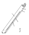
- Fig. 1 is an embodiment of a seat rail 1 with a connectable to a motor vehicle seat upper rail 2 and a connectable to a vehicle floor bottom rail 3 is shown.
- the upper rail 2 is mounted longitudinally displaceable on the lower rail 3, wherein on the seat bottom rail 3 for comfortable longitudinal adjustment via an adjusting a spindle 6 via a spindle holder 4 and a spindle mount 11 against rotation on the lower rail 3 is stored.
- the spindle 6 allows, in cooperation with a not shown, driven spindle nut of the adjusting the upper rail 2 to adjust motor relative to the lower rail 3.
- Such adjustability is an increase in comfort over a manual longitudinal adjustment, for the position securing arranged on the lower rail 3 Rastismesmarken 13 are provided, which, however, are in the case of a motor adjustment without function.
- the spindle 6 is fastened to a spindle receptacle 11, which is fastened against rotation by means of through-holes 12 on the lower rail 3.
- the spindle 6 is connected via a spindle holder 4 to the lower rail 3, the spindle holder 4 having a first attachment opening 20 and a second attachment opening 9 and the lower rail 3 having a first attachment opening 17 and a second attachment opening 16 (cf. Fig. 2 - 4c ).
- the first attachment openings 20, 17 have a polygonal, namely hexagonal cross-section and allow the arrangement of a correspondingly formed fastening means 8, 8 'in the form of a kausniets, which has a corresponding hexagonal cross-section in a connecting portion 18.
- a corresponding anti-rotation is particularly advantageous if a fastening screw 10, by means of which the seat rail 1 is fixed to a vehicle floor, through the second mounting holes 9, 16 and is bolted to the vehicle floor, as when tightening the fastening screw 10, due to friction between the fastening screw 10 and the spindle holder 4, a torque is generated, which can lead to a rotation of the spindle holder 4, as a result of which it could lead to a bending of the spindle 6, which in turn results in a stiffness.
- the spindle holder 4 has a U-shaped receiving portion 5, which surrounds a flattened connecting portion 7 of the spindle 6 with the free legs.
- the fastener formed as a rivet 8, 8 ' can be configured as desired, provided that it is ensured via the connecting portion 18 that an anti-twist device is present.
- the fastening means is designed as a rivet 8, which rests with its connecting portion 18 in the first mounting holes 20, 17 of spindle holder 4 and lower rail 3, wherein the positioning is secured on the rivet head 19.
- a second embodiment of a fastening means is in Fig. 5b illustrated, wherein the Befest Trent Whilesniet 8 'has a subsequent to the connecting portion 18 pin 15 having a tapered cross-section.
- the pin 15 is in the installed position, as in particular Fig. 3b can be seen from the bottom 14 of the lower rail 3 and makes it possible to use the rivet 8 'in addition to a rotation also for positioning the seat rail 1 on the vehicle floor.
- the tapering in the end region of the cross section 15 serves as an assembly aid.
Landscapes
- Engineering & Computer Science (AREA)
- Aviation & Aerospace Engineering (AREA)
- Transportation (AREA)
- Mechanical Engineering (AREA)
- Seats For Vehicles (AREA)
Description
- Die Erfindung betrifft eine Sitzschiene für einen Kraftfahrzeugsitz, mit
- einer mit einem Kraftfahrzeug verbindbaren Unterschiene,
- einer an der Unterschiene mittels eines Spindelhalters verdrehfest angeordneten Spindel, wobei der Spindelhalter über ein sich durch eine Befestigungsöffnung an dem Spindelhalter sowie eine Befestigungsöffnung an der Unterschiene erstreckendes Befestigungsmittel an der Unterschiene festgelegt ist.
- Sitzschienen der eingangs genannten Art sind in vielfältigen Ausgestaltungen aus dem Stand der Technik bekannt, beispielsweise aus der Druckschrift
DE 10 2006 022 947 B3 , die einen Längseinsteller für einen Kraftfahrzeugsitz offenbart, umfassend ein aus zwei relativ zueinander in Längsrichtung verschieblich angeordneten Sitzschienen gebildetes Schienenprofil, wobei beide Sitzschiene zueinander von einem Getriebe, einer Spindel sowie einer Spindelmutter bewegt werden. Die Sitzschiene des Standes der Technik dienen bei Kraftfahrzeugsitzen zur Anpassung der Sitzposition an die jeweiligen Fahrzeugnutzer, wobei die Kraftfahrzeugsitze in der Regel mit einer Oberschiene verbunden sind, welche gegenüber einer fahrzeugfest angeordneten Unterschiene verstellbar ist, so dass die Längsposition des Fahrzeugsitzes in dessen Einbaulage an die persönlichen Bedürfnisse anpassbar ist. - Moderne Kraftfahrzeugsitze weisen dabei vermehrt die Möglichkeit einer motorischen Verstellung des Kraftfahrzeugsitzes relativ gegenüber der Unterschiene auf, so dass der jeweilige Nutzer die Möglichkeit hat, die Sitzposition in besonders komfortabler Weise an seine Bedürfnisse anzupassen. Als besonders bewährt zur Verstellung haben sich dabei Antriebseinheiten, welche eine an einer Unterschiene angeordnete Spindel vorsehen, die zur Längsverstellung zur Aufnahme einer angetriebenen Spindelmutter ausgebildet ist. Das teilweise den Antriebseinheiten zugrunde liegende Funktionsprinzip erfordert es, die Spindel verdrehfest an der Unterschiene anzuordnen. Hierzu werden vorzugsweise Spindelhalter verwendet, welche die Spindel aufnehmen und mit der Unterschiene verbunden sind.
- Zur Befestigung des Spindelhalters an der Unterschiene ist es dabei bekannt, sich sowohl durch den Spindelhalter wie auch die Unterschiene erstreckende Befestigungsschrauben zu verwenden, welche neben einer Befestigung des Spindelhalters an der Unterschiene auch eine Festlegung der Unterschiene am Kraftfahrzeug ermöglichen. Beim Anziehen derartiger Bodenverschraubungen kommt es jedoch aufgrund der Reibung zwischen der Befestigungsschrauben und dem Spindelhalter zu einer Übertragung des Anzugmoments auf den Spindelhalter, was zu einer Verschwenkung des Spindelhalters gegenüber der Unterschiene führen kann, infolge dessen sich die Spindel verbiegt. Eine Befestigung des Spindelhalters über bspw. eine Nietverbindung ist nicht dazu geeignet, um eine Verdrehung des Spindelhalters bei einem Anziehen einer Bodenverschraubung zu verhindern. Eine Verbiegung der Spindel kann neben einer Geräuschbelastung - in Abhängigkeit von dem Verbiegungsgrad - darüber hinaus zu Funktionsbeeinträchtigungen führen, welche unter Umständen auch zu einem Totalausfall der Längsverstellung führen können.
- Der Erfindung liegt hiervon ausgehend die Aufgabe zugrunde, eine Sitzschiene mit einer Unterschiene bereitzustellen, an der eine Verdrehung des Spindelhalters, insbesondere im Falle einer sich durch den Spindelhalter erstreckenden Bodenverschraubung weitestgehend ausgeschlossen ist.
- Die Erfindung löst die Aufgabe durch eine Sitzschiene mit den Merkmalen des Anspruchs 1. Vorteilhafte Weiterbildungen der Erfindung sind in den abhängigen Ansprüchen angegeben.
- Kennzeichnend für die erfindungsgemäße Sitzschiene ist, dass die zur Befestigung des Spindelhalters an der Unterschiene und dem Spindelhalter vorgesehenen Befestigungsöffnungen und/oder das Befestigungsmittel in einem im Bereich der Befestigungsöffnungen angeordneten Verbindungsabschnitt einen von einer Kreisform abweichenden, vorzugsweise polygonalen Querschnitt aufweist. Gemäß der Erfindung weist der Spindelhalter sowie die Unterschiene in ihrer Einbaulage zueinander im Wesentlichen fluchtend verlaufende Befestigungsöffnungen auf, die zur Aufnahme eines die Befestigungsöffnungen durchdringenden Befestigungsmittels ausgebildet sind.
- Durch die erfindungsgemäße Ausgestaltung der Befestigungsöffnungen und/oder des Befestigungsmittels mit einem von einer Kreisform abweichenden, vorzugsweise polygonalen Querschnitt, wird eine zuverlässige Verdrehsicherung des Spindelhalters gegenüber der Unterschiene erzielt. Im Falle eines sich durch eine Befestigungsschraube hervorgerufenen, auf den Spindelhalter wirkenden Moments wird wirksam eine Verlagerung des Spindelhalters verhindert, so dass schädigende, auf die Spindel wirkende Querkräfte, welche zu einer Durchbiegung der Spindel führen, ausgeschlossen werden können. Die Ausgestaltung des Verbindungsabschnitts und/oder der Befestigungsöffnungen mit einem von einer Kreisform abweichenden Querschnitt, insbesondere mit einem polygonalen Querschnitt, verhindert dabei besonders zuverlässig eine Verdrehung des Spindelhalters gegenüber der Unterschiene, nachdem hierdurch Relativbewegungen des Spindelhalters blockiert werden. Insbesondere eine polygonale Ausgestaltung des Querschnitts bei entsprechender Ausgestaltung der Befestigungsöffnung zeichnet sich dabei durch seine besonders hohe Verdrehsicherung des Spindelhalters gegenüber der Unterschiene aus.
- Das sich durch die Befestigungsöffnungen an Spindelhalter und Unterschiene erstreckende Befestigungsmittel kann grundsätzlich in beliebiger Weise ausgebildet sein. Nach einer besonders vorteilhaften Ausgestaltung der Erfindung ist das Befestigungsmittel jedoch durch einen Verbindungsniet gebildet, dessen Querschnitt im Verbindungsabschnitt, d. h. der Bereich des Befestigungsmittels, der im montierten Zustand innerhalb der Befestigungsöffnungen angeordnet ist, an den Querschnitt der Befestigungsöffnungen angepasst ist. Der Verbindungsniet lässt sich besonders einfach anbringen und ermöglicht somit eine kostengünstige Herstellung der Sitzschiene. Insbesondere lässt sich der Verbindungsniet derart ausgestalten, dass er nur in einem geringen Bereich von einer Oberfläche der Unterschiene oder des Spindelhalters vorsteht, so dass durch den Verbindungsniet nur ein geringer Bauraum beansprucht wird.
- Die konkrete Ausgestaltung des Verbindungsabschnitts mit einem von einer Kreisform abweichenden, vorzugsweise mit einem polygonalen Querschnitt kann grundsätzlich in beliebiger Weise erfolgen. Nach einer besonders vorteilhaften Ausgestaltung der Erfindung weist der Verbindungsabschnitt des Befestigungsmittels jedoch einen viereckigen, bevorzugt einen fünfeckigen, besonders bevorzugt einen sechseckigen Querschnitt auf. Befestigungsmittel mit derart ausgestalteten Verbindungsabschnitten lassen sich besonders einfach und kostengünstig herstellen und gewährleisten überdies über ihre Seitenflächen eine besonders zuverlässige Verdrehsicherung des Spindelhalters gegenüber der Unterschiene. Besonders bewährt hat sich dabei die Ausgestaltung eines fünfeckigen, insbesondere sechseckigen Querschnitts, wodurch eine besonders spielarme bzw. spielfreie Befestigung des Spindelhalters an der Sitzschiene möglich ist.
- Wie bereits an obiger Stelle ausgeführt, ist die Ausgestaltung des Befestigungsmittels grundsätzlich frei wählbar. Nach einer besonders vorteilhaften Ausgestaltung der Erfindung ist vorgesehen, dass sich an den Verbindungsabschnitt des Befestigungsmittels ein Zapfen anschließt, der im montierten Zustand von einer dem Spindelhalter gegenüberliegenden Seite der Unterschiene vorsteht. Gemäß dieser Ausgestaltung der Erfindung ragt das Befestigungsmittel mit einem Abschnitt von der dem Spindelhalter gegenüberliegenden Seite- in der Regel der Unterseite der Unterschiene - vor. Dieser Abschnitt, d. h. der Zapfen kann zur Positionierung der Unterschiene am Kraftfahrzeug genutzt werden. Der Zapfen kann dabei als ergänzendes oder einziges Anordnungsmittel dienen, um eine besonders einfache und schnelle Positionierung der Sitzschiene am Kraftfahrzeugboden zu erreichen. Insbesondere in Verbindung mit weiteren Positionierhilfen und/oder einer Befestigungsschraube lässt sich somit auch eine Fehlmontage der Sitzschiene in besonders wirksamer Weise vermeiden.
- Nach einer besonders vorteilhaften Ausgestaltung der Erfindung weist dabei der Zapfen des Befestigungsmittels eine sich zum freien Zapfenende verjüngende Form und/oder einen polygonalen Querschnitt auf. Ein sich verjüngender Querschnitt erleichtert die Montage der Sitzschiene am Fahrzeugboden und ein polygonaler Querschnitt ermöglicht eine Ausrichtung der Sitzschiene gegenüber dem Fahrzeugboden bzw. verhindert Verdrehbewegungen der Sitzschiene und steigert somit die Positioniergenauigkeit.
- Grundsätzlich kann sich die zur Befestigung der Unterschiene an dem Kraftfahrzeug vorgesehene Befestigungsschraube in beliebiger Weise durch die Unterschiene erstrecken. Nach einer besonders vorteilhaften Ausgestaltung der Erfindung weisen der Spindelhalter und die Unterschiene jeweils eine zweite, im montierten Zustand fluchtend zueinander angeordnete Befestigungsöffnung auf, die zur Aufnahme einer Befestigungsschraube zur Festlegung der Sitzschiene an dem Kraftfahrzeug ausgebildet sind. Eine entsprechende Ausgestaltung gewährleistet, dass die Befestigungsschraube in einem Bereich mit der Unterschiene angeordnet ist, in dem durch die Materialdicke des Spindelhalters zusätzliches Material bereitsteht, welche insbesondere im Crashfall einem Ausreißen entgegenwirkt. Aufgrund der Verwendung eines erfindungsgemäßen Befestigungsmittels kann dabei zuverlässig ausgeschlossen werden, dass das beim Anziehen der Befestigungsschraube, aufgrund der Reibung auf den Spindelhalter wirkende Drehmoment zu einer Verdrehung des Spindelhalters führt, welche eine Beschädigung der Spindel zur Folge haben könnte.
- Die Anordnung der Spindel an dem Spindelhalter erfolgt in Abhängigkeit vom Funktionsprinzip der Antriebseinheit entweder verdrehsicher oder in einer verdrehbaren Weise. Nach einer besonders vorteilhaften Ausgestaltung der Erfindung weist der Spindelhalter jedoch zur verdrehsicheren Aufnahme der Spindel einen U-förmigen Aufnahmeabschnitt auf. Ein entsprechend ausgestalteter Abschnitt zur Anordnung der Spindel ermöglicht es, diese in besonders zuverlässiger Weise verdrehsicher an dem Spindelhalter zu befestigen. Hierbei umschließen die freien Schenkel des U-förmigen Abschnitts die Spindel zumindest abschnittsweise und verhindern somit zuverlässig eine Verdrehung der Spindel gegenüber dem Spindelhalter. Besonders vorteilhafterweise ist dabei auch das Befestigungsmittel im Bereich des U-förmigen Aufnahmebereichs angeordnet. Hierdurch wird die Stabilität der Verbindung in ergänzender Weise gesteigert, nachdem der Spindelhalter eine besonders hohe Steifigkeit aufweist. Insbesondere im Crashfall kann somit besonders wirksam vorgebeugt werden, dass es zu einem Ausreißen des Spindelhalters gegenüber der Unterschiene kommt.
- Nachfolgend werden Ausführungsbeispiele der Erfindung mit Bezug auf die Zeichnungen erläutert. In den Zeichnungen zeigen:
- Fig. 1
- eine perspektivische Ansicht einer Sitzschiene;
- Fig. 2
- eine perspektivische Ansicht der Sitzschiene von
Fig. 1 ohne daran angeordneter Oberschiene; - Fig. 3a
- eine perspektivische Ansicht auf eine Unterseite der Unterschiene von
Fig. 2 ; - Fig. 3b
- eine weitere perspektivische Ansicht auf die Unterschiene von
Fig. 2 mit einem von der Unterseite vorstehenden Befestigungsmittel; - Fig. 4a
- eine perspektivische Ansicht eines Teilbereichs der Sitzschiene von
Fig. 1 ; - Fig. 4b
- eine weitere perspektivische Ansicht eines Teilbereichs der Sitzschiene von
Fig. 1 teilweise im Schnitt; - Fig. 4c
- eine Draufsicht auf den in
Fig. 4a und 4b dargestellten Teilbereich der Sitzschiene vonFig. 1 ; - Fig. 5a
- eine erste Ausführungsform eines Befestigungsmittels mit polygonalem Verbindungsquerschnitt und
- Fig. 5b
- eine zweite Ausführungsform eines Befestigungsmittels mit polygonalem Verbindungsquerschnitt und sich hieran anschließendem Zapfen.
- In
Fig. 1 ist ein Ausführungsbeispiel einer Sitzschiene 1 mit einer mit einem Kraftfahrzeugsitz verbindbaren Oberschiene 2 und einer mit einem Fahrzeugboden verbindbaren Unterschiene 3 dargestellt. - Zur Längsverstellung des hier nicht dargestellten Kraftfahrzeugsitzes gegenüber dem ebenfalls nicht dargestellten Fahrzeugboden ist die Oberschiene 2 längsverschiebbar an der Unterschiene 3 gelagert, wobei an der Sitzunterschiene 3 zur komfortablen Längsverstellung über eine Verstelleinrichtung eine Spindel 6 über einen Spindelhalter 4 sowie eine Spindelaufnahme 11 verdrehsicher an der Unterschiene 3 gelagert ist.
- Die Spindel 6 erlaubt es, im Zusammenwirken mit einer hier nicht dargestellten, angetriebenen Spindelmutter der Verstelleinrichtung die Oberschiene 2 motorisch gegenüber der Unterschiene 3 zu verstellen. Eine derartige Verstellbarkeit stellt eine Komfortsteigerung gegenüber einer manuellen Längsverstellung dar, für die zur Lagesicherung die an der Unterschiene 3 angeordneten Rastierungsmarken 13 vorgesehen sind, welche jedoch im Falle einer motorischen Verstellbarkeit ohne Funktion sind.
- Einenends ist die Spindel 6 an einer Spindelaufnahme 11 befestigt, welche über Durchstellungen 12 verdrehsicher an der Unterschiene 3 befestigt ist. Anderenends ist die Spindel 6 über einen Spindelhalter 4 mit der Unterschiene 3 verbunden, wobei der Spindelhalter 4 eine erste Befestigungsöffnung 20 und eine zweite Befestigungsöffnung 9 und die Unterschiene 3 eine erste Befestigungsöffnung 17 und eine zweite Befestigungsöffnung 16 aufweisen (vgl.
Fig. 2 - 4c ). - In der montierten Lage des Spindelhalters 4 an der Unterschiene 3 sind die ersten Befestigungsöffnungen 20, 17 und die zweiten Befestigungsöffnungen 9, 16 fluchtend zueinander angeordnet. Die ersten Befestigungsöffnungen 20, 17 weisen einen polygonalen, nämlich sechseckigen Querschnitt auf und ermöglichen die Anordnung eines entsprechend ausgebildeten Befestigungsmittels 8, 8' in Form eines Verbindungsniets, welcher in einem Verbindungsabschnitt 18 einen entsprechenden sechseckigen Querschnitt aufweist. Der Befestigungsniet 8, 8' erstreckt sich durch die ersten Befestigungsöffnungen 20,17 und verhindert aufgrund des polygonalen Querschnitts des Verbindungsabschnitts 18 sowie der entsprechenden Ausgestaltung der Befestigungsöffnungen 20, 17 eine Verdrehung des Spindelhalters 4 gegenüber der Unterschiene 3.
- Eine entsprechende Verdrehsicherung ist insbesondere dann vorteilhaft, wenn sich eine Befestigungsschraube 10, mittels derer die Sitzschiene 1 an einem Fahrzeugboden befestigt wird, durch die zweiten Befestigungsöffnungen 9, 16 erstreckt und mit dem Fahrzeugboden verschraubt wird, da beim Anzug der Befestigungsschraube 10, aufgrund der Reibung zwischen der Befestigungsschraube 10 und dem Spindelhalter 4, ein Drehmoment erzeugt wird, welches zu einem Verdrehen des Spindelhalters 4 führen kann, infolge dessen es zu einer Verbiegung der Spindel 6 kommen könnte, aus der wiederum eine Schwergängigkeit resultiert.
- Zur verdrehsicheren Anordnung der Spindel 6 an dem Spindelhalter 4 weist der Spindelhalter 4 einen U-förmigen Aufnahmeabschnitt 5 auf, welcher einen abgeflachten Verbindungsabschnitt 7 der Spindel 6 mit den freien Schenkeln umgibt.
- Zur Befestigung kann das als Niet 8, 8' ausgebildete Befestigungsmittel beliebig ausgestaltet sein, sofern über den Verbindungsabschnitt 18 gewährleistet ist, dass eine Verdrehsicherung vorliegt. Gemäß einer in
Fig. 5a dargestellten Ausführungsform ist das Befestigungsmittel als Niet 8 ausgebildet, welches mit seinem Verbindungsabschnitt 18 in den ersten Befestigungsöffnungen 20, 17 von Spindelhalter 4 und Unterschiene 3 anliegt, wobei die Positionierung über den Nietkopf 19 gesichert ist. Eine zweite Ausführungsform eines Befestigungsmittels ist inFig. 5b dargestellt, wobei der Befestigungsniet 8' einen sich an den Verbindungsabschnitt 18 anschließenden Zapfen 15 mit einem sich verjüngenden Querschnitt aufweist. Der Zapfen 15 steht in der Einbaulage, wie insbesondere ausFig. 3b ersichtlich, von der Unterseite 14 der Unterschiene 3 vor und ermöglicht es, den Niet 8' neben einer Verdrehsicherung auch zur Positionierung der Sitzschiene 1 am Fahrzeugboden zu verwenden. Der sich im Endbereich verjüngende Querschnitt des Zapfens 15 dient dabei als Montagehilfe.
Claims (8)
- Sitzschiene für einen Kraftfahrzeugsitz, mit- einer mit einem Kraftfahrzeug verbindbaren Unterschiene,- einer an der Unterschiene mittels eines Spindelhalters verdrehfest angeordneten Spindel, wobei der Spindelhalter über ein sich durch eine Befestigungsöffnung an dem Spindelhalter sowie eine Befestigungsöffnung an der Unterschiene erstreckendes Befestigungsmittel an der Unterschiene festgelegt ist,dadurch gekennzeichnet, dass die Befestigungsöffnungen (17, 20) und/oder das Befestigungsmittel (8, 8') in einem im Bereich der Befestigungsöffnungen (17, 20) angeordneten Verbindungsabschnitt (18) einen von einer Kreisform abweichenden, vorzugsweise polygonalen Querschnitt aufweisen.
- Sitzschiene nach Anspruch 1, dadurch gekennzeichnet, dass das Befestigungsmittel durch einen Verbindungsniet (8, 8') gebildet ist.
- Sitzschiene nach Anspruch 1 oder 2, dadurch gekennzeichnet, dass der Verbindungsabschnitt (18) einen viereckigen, bevorzugt einen fünfeckigen, besonders bevorzugt einen sechseckigen Querschnitt aufweist.
- Sitzschiene nach einem der vorher genannten Ansprüche, dadurch gekennzeichnet, dass sich an den Verbindungsabschnitt (18) des Befestigungsmittels (8') ein von der dem Spindelhalter (4) gegenüberliegenden Seite der Unterschiene (3) vorstehender Zapfen (15) anschließt.
- Sitzschiene nach einem der vorherigen Ansprüche, dadurch gekennzeichnet, dass der Zapfen (15) eine sich zum freien Zapfenende verjüngende Form und/oder einen polygonalen Querschnitt aufweist.
- Sitzschiene nach einem der vorherigen Ansprüche, dadurch gekennzeichnet, dass der Spindelhalter (4) und die Unterschiene (3) jeweils eine zweite, korrespondierend zueinander angeordnete Befestigungsöffnung (9, 16) aufweisen, die zur Aufnahme einer Befestigungsschraube (10) zur Festlegung der Sitzschiene (1) an dem Fahrzeug ausgebildet sind.
- Sitzschiene nach einem der vorherigen Ansprüche, dadurch gekennzeichnet, dass der Spindelhalter (4) zur verdrehsicheren Aufnahme der Spindel (6) einen u-förmigen Aufnahmeabschnitt (5) aufweist.
- Sitzschiene nach einem der vorherigen Ansprüche, dadurch gekennzeichnet, dass das Befestigungsmittel (8, 8') im Bereich des u-förmigen Aufnahmeabschnittes (5) angeordnet ist.
Applications Claiming Priority (2)
| Application Number | Priority Date | Filing Date | Title |
|---|---|---|---|
| DE102011002441A DE102011002441A1 (de) | 2011-01-04 | 2011-01-04 | Sitzschiene für einen Kraftfahrzeugsitz |
| PCT/EP2011/071267 WO2012093002A1 (de) | 2011-01-04 | 2011-11-29 | Sitzschiene für einen kraftfahrzeugsitz |
Publications (2)
| Publication Number | Publication Date |
|---|---|
| EP2661380A1 EP2661380A1 (de) | 2013-11-13 |
| EP2661380B1 true EP2661380B1 (de) | 2015-07-15 |
Family
ID=45350750
Family Applications (1)
| Application Number | Title | Priority Date | Filing Date |
|---|---|---|---|
| EP11797210.9A Active EP2661380B1 (de) | 2011-01-04 | 2011-11-29 | Sitzschiene für einen kraftfahrzeugsitz |
Country Status (7)
| Country | Link |
|---|---|
| US (1) | US9242579B2 (de) |
| EP (1) | EP2661380B1 (de) |
| JP (1) | JP5771703B2 (de) |
| KR (1) | KR101547107B1 (de) |
| CN (1) | CN103298650B (de) |
| DE (1) | DE102011002441A1 (de) |
| WO (1) | WO2012093002A1 (de) |
Families Citing this family (10)
| Publication number | Priority date | Publication date | Assignee | Title |
|---|---|---|---|---|
| USD754521S1 (en) * | 2012-12-28 | 2016-04-26 | Thk Co., Ltd. | Vehicle seat rail |
| FR3025756B1 (fr) * | 2014-09-12 | 2018-03-16 | Faurecia Sieges D'automobile | Glissieres pour sieges de vehicules, siege de vehicule comportant une telle glissiere |
| KR101600191B1 (ko) | 2014-09-30 | 2016-03-07 | 주식회사다스 | 차량용 시트 레일 |
| DE102015203763A1 (de) | 2015-03-03 | 2016-09-08 | Volkswagen Aktiengesellschaft | Vorrichtung zum Befestigen eines Sitzes in einem Fahrzeug, Fahrzeugsitzanordnung |
| US10137803B2 (en) | 2015-03-20 | 2018-11-27 | Adient Luxembourg Holding S.à.r.l. | Longitudinal adjustment mechanism for a vehicle seat |
| DE102016224514A1 (de) * | 2016-12-08 | 2018-06-14 | Brose Fahrzeugteile Gmbh & Co. Kg, Coburg | Verstelleinrichtung für die Längsverstellung eines Fahrzeugsitzes |
| DE102017218492B4 (de) * | 2017-08-08 | 2022-12-22 | Keiper Seating Mechanisms Co., Ltd. | Längseinsteller und fahrzeugsitz |
| DE102018212288B4 (de) | 2018-07-24 | 2024-12-24 | Brose Fahrzeugteile SE & Co. Kommanditgesellschaft, Coburg | Verfahren zum Verbinden einer Spindel mit einem Spindelhalteelement, Längsverstelleinrichtung für einen Fahrzeugsitz |
| DE102020102867B4 (de) * | 2019-10-02 | 2024-08-22 | Keiper Seating Mechanisms Co., Ltd. | Längseinsteller für einen fahrzeugsitz und fahrzeugsitz |
| FR3106538B1 (fr) * | 2020-01-29 | 2022-01-14 | Faurecia Sieges Dautomobile | Fixation de glissière de siège de véhicule |
Family Cites Families (17)
| Publication number | Priority date | Publication date | Assignee | Title |
|---|---|---|---|---|
| GB931839A (en) * | 1960-08-09 | 1963-07-17 | Goodrich Co B F | Expansible hollow rivet |
| JPS57198224U (de) * | 1981-06-12 | 1982-12-16 | ||
| DE19639007A1 (de) * | 1996-09-23 | 1998-03-26 | Boellhoff Gmbh Verbindungs Und | Befestigungselement zum Einnieten in eine Lochkontur eines flächigen Bauteiles |
| JPH111136A (ja) * | 1997-06-12 | 1999-01-06 | Gifu Shatai Kogyo Kk | シートトラックスライド装置における部品固定構造 |
| EP0979750A3 (de) | 1998-08-12 | 2001-04-11 | C. Rob. Hammerstein GmbH & Co.KG | Farhzeugsitz mit Verstellvorrichtung, die eine Spindel und eine zugeordnete Spindelmutter hat |
| GB0107664D0 (en) | 2001-03-28 | 2001-05-16 | Emhart Inc | Blind rivet nut with improved seal retention |
| JP2004106713A (ja) | 2002-09-19 | 2004-04-08 | Shiroki Corp | パワーシートトラック |
| DE10358586B4 (de) * | 2003-12-08 | 2008-02-21 | Keiper Gmbh & Co.Kg | Getriebegehäuse eines Sitzverstellgetriebes für ein Kraftfahrzeug |
| DE102004001624B3 (de) * | 2004-01-09 | 2005-09-01 | Keiper Gmbh & Co. Kg | Antrieb einer Sitzverstelleinrichtung für ein Kraftfahrzeug |
| DE202005000317U1 (de) * | 2004-02-12 | 2005-04-07 | Keiper Gmbh & Co Kg | Längseinsteller für einen Fahrzeugsitz |
| JP4484549B2 (ja) * | 2004-03-09 | 2010-06-16 | 富士機工株式会社 | 自動車用シートスライド装置 |
| JP4857558B2 (ja) * | 2004-12-21 | 2012-01-18 | アイシン精機株式会社 | 車両用パワーシートスライド装置 |
| US7407214B2 (en) * | 2005-01-18 | 2008-08-05 | Dura Global Technologies, Inc. | Seat adjusting assembly including lead screw and mounting attachment |
| FR2882974B1 (fr) * | 2005-03-14 | 2008-11-07 | Faurecia Sieges Automobile | Mecanisme de reglage a vis, glissiere comportant un tel mecanisme de reglage et siege comportant une telle glissiere |
| DE102006022947B3 (de) * | 2006-05-17 | 2007-09-27 | Keiper Gmbh & Co.Kg | Längseinsteller für einen Fahrzeugsitz |
| JP5365225B2 (ja) | 2009-02-03 | 2013-12-11 | トヨタ紡織株式会社 | 車両用シートのスライド構造 |
| US8540203B2 (en) * | 2009-12-16 | 2013-09-24 | Keiper Gmbh & Co. Kg | Longitudinal adjuster for a vehicle seat with spindle and spindle holder |
-
2011
- 2011-01-04 DE DE102011002441A patent/DE102011002441A1/de not_active Withdrawn
- 2011-11-29 EP EP11797210.9A patent/EP2661380B1/de active Active
- 2011-11-29 US US13/978,371 patent/US9242579B2/en active Active
- 2011-11-29 KR KR1020137020687A patent/KR101547107B1/ko not_active Expired - Fee Related
- 2011-11-29 JP JP2013547829A patent/JP5771703B2/ja not_active Expired - Fee Related
- 2011-11-29 WO PCT/EP2011/071267 patent/WO2012093002A1/de not_active Ceased
- 2011-11-29 CN CN201180064093.9A patent/CN103298650B/zh active Active
Also Published As
| Publication number | Publication date |
|---|---|
| DE102011002441A1 (de) | 2012-07-05 |
| WO2012093002A1 (de) | 2012-07-12 |
| US9242579B2 (en) | 2016-01-26 |
| EP2661380A1 (de) | 2013-11-13 |
| CN103298650B (zh) | 2016-05-11 |
| KR101547107B1 (ko) | 2015-08-25 |
| JP2014501662A (ja) | 2014-01-23 |
| KR20130114711A (ko) | 2013-10-17 |
| JP5771703B2 (ja) | 2015-09-02 |
| US20140374560A1 (en) | 2014-12-25 |
| CN103298650A (zh) | 2013-09-11 |
Similar Documents
| Publication | Publication Date | Title |
|---|---|---|
| WO2012093002A1 (de) | Sitzschiene für einen kraftfahrzeugsitz | |
| DE102008007094B4 (de) | Verriegelungsvorrichtung für eine längs- und/oder neigungsverstellbare Lenksäule eines Kraftfahrzeuges | |
| EP2070761B1 (de) | Getriebebaueinheit einer Verstelleinrichtung eines Kraftfahrzeugs | |
| DE102008024154B4 (de) | Fangbügel eines Fahrzeugschlosses und Verschlussanordnung | |
| DE102017213912A1 (de) | Verstellbare Lenksäule für ein Kraftfahrzeug mit Energieabsorptionsvorrichtung | |
| WO2014048535A1 (de) | Lenksäule für ein kraftfahrzeug | |
| EP1926641A1 (de) | Scheibenwischvorrichtung, insbesondere für ein kraftfahrzeug | |
| DE112016004519T5 (de) | Gestänge für eine Lenkradkippanordnung mit Elektromotor | |
| DE102012111477B4 (de) | Sitzverstelleinrichtung, zusätzliches Getriebe und Kraftfahrzeug | |
| DE102010045423B4 (de) | Feststellvorrichtung für verstellbare Kraftfahrzeuglenksäule | |
| DE102010042008A1 (de) | Längsverstelleinrichtung für einen Kraftfahrzeugsitz | |
| DE102010010585B4 (de) | Längseinsteller für einen Fahrzeugsitz mit Spindel und Spindelhalter | |
| DE102009028458B4 (de) | Modulares Lenkerelement | |
| EP4037931B1 (de) | Längseinsteller für einen fahrzeugsitz und fahrzeugsitz | |
| DE102020108378B4 (de) | Längseinsteller und fahrzeugsitz | |
| EP2839987B1 (de) | Tragstangenbügel, Kopfstütze und Verfahren zur Montage | |
| DE102004013979B3 (de) | Vorrichtung zur Halterung einer Komponente, insbesondere eine Kopfstütze und insbesondere in oder an einem Fahrzeug | |
| DE102019110910B4 (de) | Türfeststeller | |
| DE10045806A1 (de) | Sitzlängsverstellung für einen Kraftfahrzeugsitz | |
| DE102004056574B4 (de) | Arretiervorrichtung für ein verstellbares Anschlussteil | |
| EP3178363A1 (de) | Saugbalken für eine bodenreinigungsmaschine | |
| DE10145209B4 (de) | Kopfstützenanordnung für ein Kraftfahrzeug | |
| DE102010027039A1 (de) | Vorrichtung zum Distanzausgleich zwischen zwei Karosserieteilen | |
| DE102014220131B4 (de) | Verstellvorrichtung und Fahrzeugsitz mit Verstellvorrichtung | |
| DE102007004139B4 (de) | Fahrgastsitz für Personenbeförderungsfahrzeuge |
Legal Events
| Date | Code | Title | Description |
|---|---|---|---|
| PUAI | Public reference made under article 153(3) epc to a published international application that has entered the european phase |
Free format text: ORIGINAL CODE: 0009012 |
|
| 17P | Request for examination filed |
Effective date: 20130805 |
|
| AK | Designated contracting states |
Kind code of ref document: A1 Designated state(s): AL AT BE BG CH CY CZ DE DK EE ES FI FR GB GR HR HU IE IS IT LI LT LU LV MC MK MT NL NO PL PT RO RS SE SI SK SM TR |
|
| DAX | Request for extension of the european patent (deleted) | ||
| RAP1 | Party data changed (applicant data changed or rights of an application transferred) |
Owner name: JOHNSON CONTROLS METALS AND MECHANISMS GMBH & CO. |
|
| REG | Reference to a national code |
Ref country code: DE Ref legal event code: R079 Ref document number: 502011007356 Country of ref document: DE Free format text: PREVIOUS MAIN CLASS: B60N0002060000 Ipc: B60N0002070000 |
|
| GRAP | Despatch of communication of intention to grant a patent |
Free format text: ORIGINAL CODE: EPIDOSNIGR1 |
|
| RIC1 | Information provided on ipc code assigned before grant |
Ipc: B60N 2/06 20060101ALI20150109BHEP Ipc: B60N 2/07 20060101AFI20150109BHEP |
|
| INTG | Intention to grant announced |
Effective date: 20150211 |
|
| GRAS | Grant fee paid |
Free format text: ORIGINAL CODE: EPIDOSNIGR3 |
|
| GRAA | (expected) grant |
Free format text: ORIGINAL CODE: 0009210 |
|
| AK | Designated contracting states |
Kind code of ref document: B1 Designated state(s): AL AT BE BG CH CY CZ DE DK EE ES FI FR GB GR HR HU IE IS IT LI LT LU LV MC MK MT NL NO PL PT RO RS SE SI SK SM TR |
|
| REG | Reference to a national code |
Ref country code: GB Ref legal event code: FG4D Free format text: NOT ENGLISH Ref country code: CH Ref legal event code: EP |
|
| REG | Reference to a national code |
Ref country code: IE Ref legal event code: FG4D Free format text: LANGUAGE OF EP DOCUMENT: GERMAN |
|
| REG | Reference to a national code |
Ref country code: AT Ref legal event code: REF Ref document number: 736601 Country of ref document: AT Kind code of ref document: T Effective date: 20150815 |
|
| REG | Reference to a national code |
Ref country code: DE Ref legal event code: R096 Ref document number: 502011007356 Country of ref document: DE |
|
| REG | Reference to a national code |
Ref country code: FR Ref legal event code: PLFP Year of fee payment: 5 |
|
| REG | Reference to a national code |
Ref country code: NL Ref legal event code: MP Effective date: 20150715 |
|
| REG | Reference to a national code |
Ref country code: LT Ref legal event code: MG4D |
|
| PG25 | Lapsed in a contracting state [announced via postgrant information from national office to epo] |
Ref country code: LT Free format text: LAPSE BECAUSE OF FAILURE TO SUBMIT A TRANSLATION OF THE DESCRIPTION OR TO PAY THE FEE WITHIN THE PRESCRIBED TIME-LIMIT Effective date: 20150715 Ref country code: GR Free format text: LAPSE BECAUSE OF FAILURE TO SUBMIT A TRANSLATION OF THE DESCRIPTION OR TO PAY THE FEE WITHIN THE PRESCRIBED TIME-LIMIT Effective date: 20151016 Ref country code: NO Free format text: LAPSE BECAUSE OF FAILURE TO SUBMIT A TRANSLATION OF THE DESCRIPTION OR TO PAY THE FEE WITHIN THE PRESCRIBED TIME-LIMIT Effective date: 20151015 Ref country code: FI Free format text: LAPSE BECAUSE OF FAILURE TO SUBMIT A TRANSLATION OF THE DESCRIPTION OR TO PAY THE FEE WITHIN THE PRESCRIBED TIME-LIMIT Effective date: 20150715 Ref country code: LV Free format text: LAPSE BECAUSE OF FAILURE TO SUBMIT A TRANSLATION OF THE DESCRIPTION OR TO PAY THE FEE WITHIN THE PRESCRIBED TIME-LIMIT Effective date: 20150715 |
|
| PG25 | Lapsed in a contracting state [announced via postgrant information from national office to epo] |
Ref country code: PT Free format text: LAPSE BECAUSE OF FAILURE TO SUBMIT A TRANSLATION OF THE DESCRIPTION OR TO PAY THE FEE WITHIN THE PRESCRIBED TIME-LIMIT Effective date: 20151116 Ref country code: PL Free format text: LAPSE BECAUSE OF FAILURE TO SUBMIT A TRANSLATION OF THE DESCRIPTION OR TO PAY THE FEE WITHIN THE PRESCRIBED TIME-LIMIT Effective date: 20150715 Ref country code: SE Free format text: LAPSE BECAUSE OF FAILURE TO SUBMIT A TRANSLATION OF THE DESCRIPTION OR TO PAY THE FEE WITHIN THE PRESCRIBED TIME-LIMIT Effective date: 20150715 Ref country code: RS Free format text: LAPSE BECAUSE OF FAILURE TO SUBMIT A TRANSLATION OF THE DESCRIPTION OR TO PAY THE FEE WITHIN THE PRESCRIBED TIME-LIMIT Effective date: 20150715 Ref country code: HR Free format text: LAPSE BECAUSE OF FAILURE TO SUBMIT A TRANSLATION OF THE DESCRIPTION OR TO PAY THE FEE WITHIN THE PRESCRIBED TIME-LIMIT Effective date: 20150715 Ref country code: ES Free format text: LAPSE BECAUSE OF FAILURE TO SUBMIT A TRANSLATION OF THE DESCRIPTION OR TO PAY THE FEE WITHIN THE PRESCRIBED TIME-LIMIT Effective date: 20150715 |
|
| REG | Reference to a national code |
Ref country code: DE Ref legal event code: R097 Ref document number: 502011007356 Country of ref document: DE |
|
| PG25 | Lapsed in a contracting state [announced via postgrant information from national office to epo] |
Ref country code: SK Free format text: LAPSE BECAUSE OF FAILURE TO SUBMIT A TRANSLATION OF THE DESCRIPTION OR TO PAY THE FEE WITHIN THE PRESCRIBED TIME-LIMIT Effective date: 20150715 Ref country code: EE Free format text: LAPSE BECAUSE OF FAILURE TO SUBMIT A TRANSLATION OF THE DESCRIPTION OR TO PAY THE FEE WITHIN THE PRESCRIBED TIME-LIMIT Effective date: 20150715 Ref country code: IT Free format text: LAPSE BECAUSE OF FAILURE TO SUBMIT A TRANSLATION OF THE DESCRIPTION OR TO PAY THE FEE WITHIN THE PRESCRIBED TIME-LIMIT Effective date: 20150715 Ref country code: DK Free format text: LAPSE BECAUSE OF FAILURE TO SUBMIT A TRANSLATION OF THE DESCRIPTION OR TO PAY THE FEE WITHIN THE PRESCRIBED TIME-LIMIT Effective date: 20150715 Ref country code: CZ Free format text: LAPSE BECAUSE OF FAILURE TO SUBMIT A TRANSLATION OF THE DESCRIPTION OR TO PAY THE FEE WITHIN THE PRESCRIBED TIME-LIMIT Effective date: 20150715 |
|
| PLBE | No opposition filed within time limit |
Free format text: ORIGINAL CODE: 0009261 |
|
| STAA | Information on the status of an ep patent application or granted ep patent |
Free format text: STATUS: NO OPPOSITION FILED WITHIN TIME LIMIT |
|
| PG25 | Lapsed in a contracting state [announced via postgrant information from national office to epo] |
Ref country code: RO Free format text: LAPSE BECAUSE OF FAILURE TO SUBMIT A TRANSLATION OF THE DESCRIPTION OR TO PAY THE FEE WITHIN THE PRESCRIBED TIME-LIMIT Effective date: 20150715 |
|
| 26N | No opposition filed |
Effective date: 20160418 |
|
| PG25 | Lapsed in a contracting state [announced via postgrant information from national office to epo] |
Ref country code: MC Free format text: LAPSE BECAUSE OF FAILURE TO SUBMIT A TRANSLATION OF THE DESCRIPTION OR TO PAY THE FEE WITHIN THE PRESCRIBED TIME-LIMIT Effective date: 20150715 Ref country code: LU Free format text: LAPSE BECAUSE OF FAILURE TO SUBMIT A TRANSLATION OF THE DESCRIPTION OR TO PAY THE FEE WITHIN THE PRESCRIBED TIME-LIMIT Effective date: 20151129 Ref country code: IS Free format text: LAPSE BECAUSE OF FAILURE TO SUBMIT A TRANSLATION OF THE DESCRIPTION OR TO PAY THE FEE WITHIN THE PRESCRIBED TIME-LIMIT Effective date: 20150715 |
|
| REG | Reference to a national code |
Ref country code: CH Ref legal event code: PL |
|
| GBPC | Gb: european patent ceased through non-payment of renewal fee |
Effective date: 20151129 |
|
| PG25 | Lapsed in a contracting state [announced via postgrant information from national office to epo] |
Ref country code: CH Free format text: LAPSE BECAUSE OF NON-PAYMENT OF DUE FEES Effective date: 20151130 Ref country code: LI Free format text: LAPSE BECAUSE OF NON-PAYMENT OF DUE FEES Effective date: 20151130 |
|
| REG | Reference to a national code |
Ref country code: IE Ref legal event code: MM4A |
|
| PG25 | Lapsed in a contracting state [announced via postgrant information from national office to epo] |
Ref country code: SI Free format text: LAPSE BECAUSE OF FAILURE TO SUBMIT A TRANSLATION OF THE DESCRIPTION OR TO PAY THE FEE WITHIN THE PRESCRIBED TIME-LIMIT Effective date: 20150715 |
|
| PG25 | Lapsed in a contracting state [announced via postgrant information from national office to epo] |
Ref country code: IE Free format text: LAPSE BECAUSE OF NON-PAYMENT OF DUE FEES Effective date: 20151129 Ref country code: GB Free format text: LAPSE BECAUSE OF NON-PAYMENT OF DUE FEES Effective date: 20151129 |
|
| REG | Reference to a national code |
Ref country code: FR Ref legal event code: PLFP Year of fee payment: 6 |
|
| REG | Reference to a national code |
Ref country code: DE Ref legal event code: R081 Ref document number: 502011007356 Country of ref document: DE Owner name: KEIPER SEATING MECHANISMS CO., LTD., CN Free format text: FORMER OWNER: JOHNSON CONTROLS METALS AND MECHANISMS GMBH & CO. KG, 42699 SOLINGEN, DE Ref country code: DE Ref legal event code: R081 Ref document number: 502011007356 Country of ref document: DE Owner name: ADIENT LUXEMBOURG HOLDING S.A R.L., LU Free format text: FORMER OWNER: JOHNSON CONTROLS METALS AND MECHANISMS GMBH & CO. KG, 42699 SOLINGEN, DE Ref country code: DE Ref legal event code: R081 Ref document number: 502011007356 Country of ref document: DE Owner name: ADIENT LUXEMBOURG HOLDING S.A.R.L., LU Free format text: FORMER OWNER: JOHNSON CONTROLS METALS AND MECHANISMS GMBH & CO. KG, 42699 SOLINGEN, DE |
|
| PG25 | Lapsed in a contracting state [announced via postgrant information from national office to epo] |
Ref country code: SM Free format text: LAPSE BECAUSE OF FAILURE TO SUBMIT A TRANSLATION OF THE DESCRIPTION OR TO PAY THE FEE WITHIN THE PRESCRIBED TIME-LIMIT Effective date: 20150715 Ref country code: BG Free format text: LAPSE BECAUSE OF FAILURE TO SUBMIT A TRANSLATION OF THE DESCRIPTION OR TO PAY THE FEE WITHIN THE PRESCRIBED TIME-LIMIT Effective date: 20150715 Ref country code: HU Free format text: LAPSE BECAUSE OF FAILURE TO SUBMIT A TRANSLATION OF THE DESCRIPTION OR TO PAY THE FEE WITHIN THE PRESCRIBED TIME-LIMIT; INVALID AB INITIO Effective date: 20111129 |
|
| PG25 | Lapsed in a contracting state [announced via postgrant information from national office to epo] |
Ref country code: CY Free format text: LAPSE BECAUSE OF FAILURE TO SUBMIT A TRANSLATION OF THE DESCRIPTION OR TO PAY THE FEE WITHIN THE PRESCRIBED TIME-LIMIT Effective date: 20150715 Ref country code: NL Free format text: LAPSE BECAUSE OF FAILURE TO SUBMIT A TRANSLATION OF THE DESCRIPTION OR TO PAY THE FEE WITHIN THE PRESCRIBED TIME-LIMIT Effective date: 20150715 |
|
| PG25 | Lapsed in a contracting state [announced via postgrant information from national office to epo] |
Ref country code: BE Free format text: LAPSE BECAUSE OF NON-PAYMENT OF DUE FEES Effective date: 20151130 |
|
| PG25 | Lapsed in a contracting state [announced via postgrant information from national office to epo] |
Ref country code: MT Free format text: LAPSE BECAUSE OF FAILURE TO SUBMIT A TRANSLATION OF THE DESCRIPTION OR TO PAY THE FEE WITHIN THE PRESCRIBED TIME-LIMIT Effective date: 20150715 |
|
| REG | Reference to a national code |
Ref country code: FR Ref legal event code: PLFP Year of fee payment: 7 |
|
| REG | Reference to a national code |
Ref country code: AT Ref legal event code: MM01 Ref document number: 736601 Country of ref document: AT Kind code of ref document: T Effective date: 20161129 |
|
| PG25 | Lapsed in a contracting state [announced via postgrant information from national office to epo] |
Ref country code: AT Free format text: LAPSE BECAUSE OF NON-PAYMENT OF DUE FEES Effective date: 20161129 |
|
| REG | Reference to a national code |
Ref country code: DE Ref legal event code: R081 Ref document number: 502011007356 Country of ref document: DE Owner name: KEIPER SEATING MECHANISMS CO., LTD., CN Free format text: FORMER OWNER: ADIENT LUXEMBOURG HOLDING S.A.R.L., LUXEMBOURG, LU Ref country code: DE Ref legal event code: R081 Ref document number: 502011007356 Country of ref document: DE Owner name: ADIENT LUXEMBOURG HOLDING S.A R.L., LU Free format text: FORMER OWNER: ADIENT LUXEMBOURG HOLDING S.A.R.L., LUXEMBOURG, LU |
|
| PG25 | Lapsed in a contracting state [announced via postgrant information from national office to epo] |
Ref country code: MK Free format text: LAPSE BECAUSE OF FAILURE TO SUBMIT A TRANSLATION OF THE DESCRIPTION OR TO PAY THE FEE WITHIN THE PRESCRIBED TIME-LIMIT Effective date: 20150715 |
|
| PG25 | Lapsed in a contracting state [announced via postgrant information from national office to epo] |
Ref country code: TR Free format text: LAPSE BECAUSE OF FAILURE TO SUBMIT A TRANSLATION OF THE DESCRIPTION OR TO PAY THE FEE WITHIN THE PRESCRIBED TIME-LIMIT Effective date: 20150715 Ref country code: AL Free format text: LAPSE BECAUSE OF FAILURE TO SUBMIT A TRANSLATION OF THE DESCRIPTION OR TO PAY THE FEE WITHIN THE PRESCRIBED TIME-LIMIT Effective date: 20150715 |
|
| REG | Reference to a national code |
Ref country code: DE Ref legal event code: R082 Ref document number: 502011007356 Country of ref document: DE Representative=s name: KUTZENBERGER WOLFF & PARTNER PATENTANWALTSPART, DE Ref country code: DE Ref legal event code: R081 Ref document number: 502011007356 Country of ref document: DE Owner name: KEIPER SEATING MECHANISMS CO., LTD., CN Free format text: FORMER OWNER: ADIENT YANFENG SEATING MECHANISMS CO., LTD., SHANGHAI, CN Ref country code: DE Ref legal event code: R081 Ref document number: 502011007356 Country of ref document: DE Owner name: KEIPER SEATING MECHANISMS CO., LTD., CN Free format text: FORMER OWNER: ADIENT LUXEMBOURG HOLDING S.A R.L., LUXEMBOURG, LU Ref country code: DE Ref legal event code: R082 Ref document number: 502011007356 Country of ref document: DE Representative=s name: LIEDTKE & PARTNER PATENTANWAELTE, DE |
|
| REG | Reference to a national code |
Ref country code: DE Ref legal event code: R082 Ref document number: 502011007356 Country of ref document: DE Representative=s name: KUTZENBERGER WOLFF & PARTNER PATENTANWALTSPART, DE |
|
| PGFP | Annual fee paid to national office [announced via postgrant information from national office to epo] |
Ref country code: FR Payment date: 20250930 Year of fee payment: 15 |
|
| PGFP | Annual fee paid to national office [announced via postgrant information from national office to epo] |
Ref country code: DE Payment date: 20250930 Year of fee payment: 15 |