EP2657166A2 - Dispositif de retournement pour produits plats en papier, matière synthétique et analogues et procédé de retournement de produits plats de ce type - Google Patents
Dispositif de retournement pour produits plats en papier, matière synthétique et analogues et procédé de retournement de produits plats de ce type Download PDFInfo
- Publication number
- EP2657166A2 EP2657166A2 EP13002200.7A EP13002200A EP2657166A2 EP 2657166 A2 EP2657166 A2 EP 2657166A2 EP 13002200 A EP13002200 A EP 13002200A EP 2657166 A2 EP2657166 A2 EP 2657166A2
- Authority
- EP
- European Patent Office
- Prior art keywords
- turning
- ring
- product
- transport
- turning device
- Prior art date
- Legal status (The legal status is an assumption and is not a legal conclusion. Google has not performed a legal analysis and makes no representation as to the accuracy of the status listed.)
- Withdrawn
Links
Images


Classifications
-
- B—PERFORMING OPERATIONS; TRANSPORTING
- B65—CONVEYING; PACKING; STORING; HANDLING THIN OR FILAMENTARY MATERIAL
- B65H—HANDLING THIN OR FILAMENTARY MATERIAL, e.g. SHEETS, WEBS, CABLES
- B65H15/00—Overturning articles
- B65H15/016—Overturning articles employing rotary or reciprocating elements supporting transport means
-
- B—PERFORMING OPERATIONS; TRANSPORTING
- B65—CONVEYING; PACKING; STORING; HANDLING THIN OR FILAMENTARY MATERIAL
- B65H—HANDLING THIN OR FILAMENTARY MATERIAL, e.g. SHEETS, WEBS, CABLES
- B65H2301/00—Handling processes for sheets or webs
- B65H2301/30—Orientation, displacement, position of the handled material
- B65H2301/33—Modifying, selecting, changing orientation
- B65H2301/332—Turning, overturning
- B65H2301/3321—Turning, overturning kinetic therefor
- B65H2301/33212—Turning, overturning kinetic therefor about an axis parallel to the direction of displacement of material
-
- B—PERFORMING OPERATIONS; TRANSPORTING
- B65—CONVEYING; PACKING; STORING; HANDLING THIN OR FILAMENTARY MATERIAL
- B65H—HANDLING THIN OR FILAMENTARY MATERIAL, e.g. SHEETS, WEBS, CABLES
- B65H2403/00—Power transmission; Driving means
- B65H2403/20—Belt drives
- B65H2403/21—Timing belts
-
- B—PERFORMING OPERATIONS; TRANSPORTING
- B65—CONVEYING; PACKING; STORING; HANDLING THIN OR FILAMENTARY MATERIAL
- B65H—HANDLING THIN OR FILAMENTARY MATERIAL, e.g. SHEETS, WEBS, CABLES
- B65H2404/00—Parts for transporting or guiding the handled material
- B65H2404/10—Rollers
- B65H2404/14—Roller pairs
- B65H2404/142—Roller pairs arranged on movable frame
- B65H2404/1421—Roller pairs arranged on movable frame rotating, pivoting or oscillating around an axis, e.g. parallel to the roller axis
- B65H2404/14212—Roller pairs arranged on movable frame rotating, pivoting or oscillating around an axis, e.g. parallel to the roller axis rotating, pivoting or oscillating around an axis perpendicular to the roller axis
Definitions
- the invention relates to a turning device for flat products made of paper, plastic and the like according to the preamble of claim 1 and a method for turning such flat products of paper, plastic and the like according to the preamble of claim 12.
- Turning devices are known with which flat products, such as single sheets, are turned.
- the turning device is located between two transport planes, on which the product is first fed to the turning device and discharged after the turning process.
- the product enters the turning device, is stopped and then turned. After the turning process, the product leaves the turning device on the other transport plane on which it is discharged.
- This transport plane lies at a different height than the transport plane used before the turning device for feeding the products.
- turning devices consist of an entangled transport belt drive.
- the product is located between the Transport belt and is transported over a longer distance with them. Due to the entanglement of the transport belt here the product is turned.
- the entangled Transporttriementriebe for larger or thicker products are less suitable. The products may shift between the belts during transport and must be realigned after turning.
- these turning devices have a considerable length, so that a correspondingly large installation space is necessary.
- the invention has the object of providing the generic turning device and the generic method in such a way that in a simple constructive and space-saving design high transport speeds and high clock speeds during the turning process are possible, and it should also be possible that the products can run through the turning device without being turned around.
- the axis of rotation is at the level of the transport planes and extends in the transport direction. Therefore, after the turning process, the product is at the level of the transport plane intended for the removal of the turned product, so that the product can be immediately transported further. Additional equipment to bring the turned product on the level of this transport level, are not required. It is also possible to transport the product without a turning process by the turning device, since the two transport planes are equal to the axis of rotation of the turning device. Therefore, the products can either be subjected to a turning process during their transport or transported without turning through the turning device become. With the turning device according to the invention, it is thus possible to achieve a high speed or a high number of cycles and to selectively achieve a turning operation without changing the transport planes.
- the recording is part of a turning ring. It is characterized by a compact design.
- the turning ring is rotated by a Endlostrieb about its axis.
- the endless drive advantageously has a toothed belt with which a slip-free rotary drive of the reversing ring is ensured.
- the turning ring is provided with transport rollers for the product. With them, the product can at least be held during the turning process, but preferably also be transported on.
- the transport rollers preferably sit on mutually parallel shafts, which in turn are rotatably mounted in the turning ring. With such a design, the product can be transported between the transport rollers and held with them during the turning process. If no turning operation is to be performed, then the transport rollers serve to transport the product without turning through the turning device from one to the other transport plane.
- the drive of the shafts is advantageously derived from a drive ring.
- the drive ring contributes to a compact design of the turning device.
- the drive ring is rotatably driven by a Endlostrieb.
- a endless drive advantageously has a toothed belt with which a slip-free drive of the drive ring is ensured.
- the waves of the turning ring are drive-connected to the drive ring via a gear transmission.
- the waves of the turning ring can be driven easily rotatable.
- the gear transmission is formed in an advantageous embodiment in that sitting on the shafts of the turning ring gears, which engage in a face gear of the drive ring. By turning the drive ring, the gears of the shafts are driven via the spur toothing.
- the spur gear is preferably a crown gear teeth.
- a simple and compact design results when the turning ring and the drive ring are coaxial with each other and / or are rotatably supported side by side in a carrier.
- the product is transported during the turning process in the recording so that it is at the end of the turning process in height of the transport plane for discharging the turned product.
- the turned product can be transported immediately after the turning process.
- the transport path of the product during the turning process is smaller than the length / width of the product measured in the transport direction. As a result, the product is still in the receptacle of the turning device at the end of the turning process.
- the transport can be kept short in this way.
- the product is advantageously held reliably when it is transported by transport rollers, between which the product is located.
- the product can be transported by the transport rollers without turning operation between the transport rollers on the subsequent transport plane.
- the transport rollers are driven independently of the drive for the turning process.
- the speed of the transport rollers can be easily adapted to the speed of the turning ring.
- the turning ring can stand still while the transport rollers continue to be driven to transport the product without turning through the turning device.
- the turning device serves to turn flat products of paper, plastic and the like, such as cut sheets, envelopes, flat piles and the like.
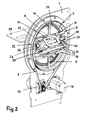
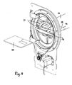
- the turning device has as a carrier a base plate 1, in which a turning ring 2 and a drive ring 3 are rotatably mounted about an axis 37.
- the turning ring 2 and the drive ring 3 are coaxial with each other and side by side and are each axially secured by retaining rings 4, 5, which are screwed to both sides of the base plate 1.
- the reversing ring 2 has a base plate 1 projecting ring 6 over which a drive belt 7 is placed. It is designed as a toothed belt, in which engages a gear 8, which sits on a shaft 9 of a drive motor 10.
- the drive motor 10 is advantageously a servomotor, which is fastened to the base plate 1. It lies at a distance from the securing rings 4, 5.
- the drive belt 7 is driven properly due to its positive engagement with the gear 8, so that the reversing ring 2 is reliably rotated in the turning process to be described.
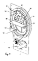
- the drive ring 3 also has a ring 11 ( Fig. 1 ), over which a drive belt 12 is placed and which projects beyond the other side of the base plate 1.
- the drive belt 12 is formed as a toothed belt and in engagement with a gear 13, which sits on a shaft 14 of a drive motor 15. It is advantageous a servo drive with which the drive ring 3 can be reliably rotated about its axis 37.
- the positive connection of the gear 13 with the drive belt 12 ensures that the drive ring 3 is reliably rotated.
- Fig. 1 and 2 shows the drive belts 7 and 12 for the turning ring 2 and the drive ring 3 on opposite sides of the base plate 1.
- the corresponding rings 6, 11 lead the drive belt 7, 12 and are on the retaining rings 4, 5 so far on that they safely from the drive belt 7, 12 can be detected.
- the outside of the rings 6, 11 is advantageously provided with a toothing, in which the drive belt 7, 12 formed as a toothed belt engage. In this way, a slip between the rings 6, 11 and the drive belt 7, 12 is prevented, so that the turning ring 2 and the drive ring 3 are properly rotated during the turning process. That's the way it is possible to achieve very high numbers of cycles with the turning device, without affecting the safety during the turning process.
- the turning ring 2 is stiffened by transverse struts 16 to 19.
- the transverse struts 16, 17 each perpendicular to the transverse struts 18 and 19, which extend parallel to each other.
- In the region between these transverse struts 18, 19 are two shafts 20, which are parallel to each other and each carry at least one transport roller 21. In the exemplary embodiment sit on each shaft 20 at a distance from each other two transport rollers 21st
- each shaft 20 sits at the ends facing away from each other a gear 22.
- the shafts 20 are rotatably mounted in bearing parts 23, 24. They are mounted in recesses 25, 26 on the inside of the turning ring 2.
- the gears 22 engage in a spur gear, preferably a crown gear 27 of the drive ring 3 a. If the drive ring 3 is rotated about its axis, then the shafts 20 and thus the transport rollers 21 are rotated via the gears 22. Between the transport rollers 21, the product to be turned 28 is introduced.
- the transport rollers 21 may consist of elastically yielding material or even have only a coating consisting of elastic material. The introduced between the transport rollers 21 product 28 is then held securely by appropriate elastic deformation during the turning process.
- a receptacle 29 is attached, which receives the product to be turned 28 for the turning process.
- the receptacle 29 has two spaced-apart frame-shaped guide members 30, 31, between which the product to be turned 28 is pushed.
- the guide elements 30, 31 are provided with perforations 32, 33, so that the transport rollers 21 come into contact with the product 28.
- the guide elements 30, 31 are each secured to the transverse struts 18, 19 by holding elements 34, 35.
- the product 28 supplied by a feed device (not shown) is located in a transport plane 28 (FIG. Fig. 1 ) and is moved between the two guide elements 30, 31 of the receptacle 29. With this feeding device, the product is pushed so far between the guide elements 30, 31 until it comes into contact with the transport rollers 21.
- the drive motor 10 of the turning ring 2 is automatically started.
- the drive ring 3 is already rotated about its axis by the drive motor 15, while the feed device 28 feeds the product.
- the direction of rotation of the drive ring 3 is adjusted so that the product 28 is drawn into the receptacle 29 as soon as it is detected by the transport rollers 21.
- the reversing ring 2 and the drive ring 3 are driven by the respective drive motors 10, 15 so that the drive ring 3 rotates faster by that amount than the propulsion of the product 28, which it should have during the turning process.
- the rotational speeds of turning ring 2 and drive ring 3 are coordinated so that during the turning process, the transport rollers 21 further transport the product 28 in the receptacle 29 so that at the end of the turning process, the turned product 28 is picked up by a removal device and transported further in the turned position can be.
- Fig. 1 shows the product 28 still at a distance from the turning device.
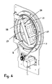
- the feed device (not shown) transports the product 28 into the receptacle 29 until it is detected by the transport rollers 21 in the manner described ( Fig. 5 ).
- the drive motor 10 is turned on, whereby the turning ring 2 is rotated about the drive belt 7 about its axis.
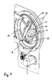
- the Fig. 6 and 7 show intermediate positions of the turning ring 2 in this turning process.
- the drive ring 3 is constantly driven by the drive belt 12, whereby the shafts 20 of the turning ring 2 are rotated via the crown gear teeth 27 and the gears 22 engaging in them.
- the product is therefore continuously transported during the turning process in the receptacle 29 of the transport rollers 21.
- Fig. 8 shows the turning ring 2 after a 180 ° turn.
- the drive motor 10 is stopped, so that the reversing ring 2 stops in the position shown. In this position, the turned product 28 is not yet released from the transport rollers 21.
- the speed of the drive ring 3 is changed in this position by means of the drive motor 15 so that the turned product 28 is released from the transport rollers 21 only when a (not shown) transport device can take over the turned product 28.
- sensors 40, 41 are provided ( Fig. 5 ) monitoring the inlet and outlet of the products 28 in the turning device.
- the sensors 40, 41 which are, for example, light guides - photo switches or light barriers, are fastened to the base plate 1 by means of holding brackets 42, 43.
- the brackets 42, 43 are formed so that the sensors 40, 41 have no contact with the turning ring 2 and the drive ring 3.
- the sensors 40, 41 are placed as close as possible to the shafts 20 and the transport rollers 21 for optimum performance and evaluate the passing of the leading edge 44 and the trailing edge 36 of the product 28 (FIG. Fig. 9 ).
- the next product to be used 28 can be supplied in the manner described. Then a new turning cycle begins.
- the turned product 28 is on a Transport level 39, which is at the same height as the inlet-side transport plane 38.
- the axis of rotation 37 of the turning ring 2 and the drive ring 3 is equal to the two transport planes 38, 39 and extends in the transport direction of the product 28 (FIG. Fig. 1 ). This ensures that the product 28 is after the turning process in the amount of the output side transport plane 39.
- the product 28, without being turned can be transported from the transport plane 38 through the turning device to the transport plane 39.
- the two guide elements 30, 31 of the receptacle 29 are arranged in the starting position of the Wenderinges 2 so that the product 28 is transported into the receptacle 29.
- the drive ring 3 is rotatably driven in the described manner when the turning ring 2 is stationary, so that the transport rollers 21 transport the product 28 without turning through the turning device.
- the speed with which the products 28 are successively fed to the turning device is adjusted so that the time interval between the release of the turned product 28 and the feed of the product to be used is minimal. Since the reversing ring 2 and the drive ring 3 are rotatably driven independently of each other, this tuning can be made reliably with high precision. The turning device thus works perfectly with a very high number of cycles.
- the transport rollers 21 are always driven in the same direction, so that a reversal of the drive ring 3 is not required. Thereby, the cycle time for the delivery and the delivery of the products 28 can be kept very small.
- the reversing ring 2 is driven discontinuously in contrast to the drive ring 3. So that the product 28 can be transported into the receptacle 29 of the reversing ring 2, the reversing ring 2 must stand still. Only when the introduced into the receptacle 29 product 28 has been taken over by the transport rollers 21 and the feeder has released the product 28, the turning ring 2 is rotated by 180 °.
- the drive ring 3 is driven with the drive motor 15 at such a speed that the product 28 is always conveyed during the turning process of the transport rollers 21 so that the product at the end of the turning process is still held by the transport rollers 21 until the subsequent Transport device can take over the turned product 28. This ensures that the product is always held between the transport rollers 21 during the turning process, so that the turning operation can be carried out reliably.
- the turning device allows high speeds or high clock speeds.
- the turning device is characterized by a short and stable design. Since the reversing ring 2 and the drive ring 3 are driven independently of each other, there is also the possibility that the product 28 is transported through the receptacle 29 without a turning process taking place. In this way, with the turning device selectively depending on the application, the product can be turned or not turned.
- the receptacle 29 is located centrally in the reversing ring 2. As a result, the product 28 is before and after the turning process in the same plane, so that the transport plane for the product 28 does not have to be changed.
- the transport rollers 21 ensure in the manner described that the product 28 is not displaced during the turning process. This also eliminates an alignment process, as is the case with conventional turning devices.
- the turning device it is possible in a simple manner to turn the products 28 not only by 180 °, but, for example, only to rotate by 90 °.
- This is advantageous, for example, when the feed device is arranged in front of and the transport device behind the turning device at right angles to one another.
- the turning ring 2 is stopped in each case after a rotation of 90 °.
- the rotational speed of the drive ring 3 is then at the corresponding smaller angle of rotation matched the turning ring 2.
- One possible application is the placement of lying products or vice versa.
- the turning device can be easily installed in existing systems, where a turning of the product is required.
Landscapes
- Engineering & Computer Science (AREA)
- Mechanical Engineering (AREA)
- Attitude Control For Articles On Conveyors (AREA)
Applications Claiming Priority (1)
| Application Number | Priority Date | Filing Date | Title |
|---|---|---|---|
| DE102012008504A DE102012008504A1 (de) | 2012-04-25 | 2012-04-25 | Wendevorrichtung für flache Produkte aus Papier, Kunststoff und dergleichen sowie Verfahren zum Wenden von solchen flachen Produkten |
Publications (1)
| Publication Number | Publication Date |
|---|---|
| EP2657166A2 true EP2657166A2 (fr) | 2013-10-30 |
Family
ID=48190685
Family Applications (1)
| Application Number | Title | Priority Date | Filing Date |
|---|---|---|---|
| EP13002200.7A Withdrawn EP2657166A2 (fr) | 2012-04-25 | 2013-04-25 | Dispositif de retournement pour produits plats en papier, matière synthétique et analogues et procédé de retournement de produits plats de ce type |
Country Status (2)
| Country | Link |
|---|---|
| EP (1) | EP2657166A2 (fr) |
| DE (1) | DE102012008504A1 (fr) |
Cited By (4)
| Publication number | Priority date | Publication date | Assignee | Title |
|---|---|---|---|---|
| CN104891226A (zh) * | 2015-06-01 | 2015-09-09 | 上海同韵环保能源科技有限公司 | 一种风电叶片翻转装置 |
| CN105729213A (zh) * | 2016-04-30 | 2016-07-06 | 临清兴和宏鑫机床有限公司 | 翻转机构 |
| CN111807104A (zh) * | 2020-07-14 | 2020-10-23 | 瑞安市方大信封机械有限公司 | 一种一体化信封装订运输台 |
| CN114193065A (zh) * | 2021-12-29 | 2022-03-18 | 宁夏鑫中奥智能装备有限公司 | 中部槽专用开放式联动焊接变位机 |
-
2012
- 2012-04-25 DE DE102012008504A patent/DE102012008504A1/de not_active Withdrawn
-
2013
- 2013-04-25 EP EP13002200.7A patent/EP2657166A2/fr not_active Withdrawn
Non-Patent Citations (1)
| Title |
|---|
| None |
Cited By (6)
| Publication number | Priority date | Publication date | Assignee | Title |
|---|---|---|---|---|
| CN104891226A (zh) * | 2015-06-01 | 2015-09-09 | 上海同韵环保能源科技有限公司 | 一种风电叶片翻转装置 |
| CN105729213A (zh) * | 2016-04-30 | 2016-07-06 | 临清兴和宏鑫机床有限公司 | 翻转机构 |
| CN105729213B (zh) * | 2016-04-30 | 2018-06-08 | 临清兴和宏鑫机床有限公司 | 翻转机构 |
| CN111807104A (zh) * | 2020-07-14 | 2020-10-23 | 瑞安市方大信封机械有限公司 | 一种一体化信封装订运输台 |
| CN111807104B (zh) * | 2020-07-14 | 2022-04-08 | 瑞安市方大信封机械有限公司 | 一种一体化信封装订运输台 |
| CN114193065A (zh) * | 2021-12-29 | 2022-03-18 | 宁夏鑫中奥智能装备有限公司 | 中部槽专用开放式联动焊接变位机 |
Also Published As
| Publication number | Publication date |
|---|---|
| DE102012008504A1 (de) | 2013-10-31 |
Similar Documents
| Publication | Publication Date | Title |
|---|---|---|
| EP2199240B1 (fr) | Dispositif destiné à la séparation de pièces | |
| DE3911859A1 (de) | Verfahren und vorrichtung zum abteilen eines von einer fuellmaschine kommenden durchgehenden wurststranges in einzelne wuerste | |
| DE3420336A1 (de) | Papierblatt-ablagevorrichtung | |
| EP3400805A1 (fr) | Dispositif et procédé de transfert et d'insertion de groupes de saucisses dans un emballage | |
| DE1782864A1 (de) | Vorrichtung zum wenden von in einer reihe kontinuierlich angelieferten zigaretten | |
| DE2401340C3 (de) | Einwickelvorrichtung in einer Münzverpackungsmaschine | |
| EP2657166A2 (fr) | Dispositif de retournement pour produits plats en papier, matière synthétique et analogues et procédé de retournement de produits plats de ce type | |
| DE2747799C2 (fr) | ||
| EP0302376A3 (fr) | Appareil et procédé de tri porteurs d'enregistrement en forme de feuilles, délivrés par une machine de bureau | |
| EP1084977A2 (fr) | Méthode pour transporter des feuilles et dispositif pour sa mise en oeuvre | |
| DE2164215C3 (de) | Vorrichtung zum Transportieren eines bahnförmigen randgelochten Materials | |
| DE3818959C2 (de) | Maschine zum Anbringen von Zigarettenfiltern | |
| DE3909373C2 (fr) | ||
| EP2896490B1 (fr) | Entraînement de lame circulaire, en particulier pour des trancheuses à pain | |
| DD216422A5 (de) | Vorrichtung zum vereinzelten zufuehren von blaettern zur schreibwalze einer bueromaschine | |
| EP3186180B1 (fr) | DISPOSITIF D'EMPILAGE DE DOCUMENTS DE VALEUR, PROCÉDÉ & xA;D'EMPILAGE DE DOCUMENTS DE VALEUR AVEC TEL DISPOSITIF D'EMPILAGE, ET DISPOSITIF DE TRAITEMENT DE DOCUMENTS DE VALEUR AVEC TEL DISPOSITIF D'EMPILAGE | |
| DE3214457C2 (fr) | ||
| DE102017128349A1 (de) | Kantenbearbeitungsanordnung | |
| DE2231088C3 (de) | Vorrichtung zum Sortieren und Zählen von Münzen verschiedener Größe | |
| DE2755210C3 (de) | Heftklammerschließvorrichtung | |
| DE1574639B2 (de) | Vorrichtung zum ausrichten eines in einer richtung bewegbaren bandes oder bandabschnittes aus klebrigem reifenbaumaterial in bezug auf eine zur foerderrichtung parallele lotrechte bezugsebene | |
| DE102021125587B3 (de) | Vorrichtung und Verfahren zum Ausrichten von Würsten | |
| EP0982253B1 (fr) | Dispositif pour traiter des produits flexibles et plats | |
| DE2007368A1 (de) | Vorrichtung zum ziehharmonikaartigen Falten von Bögen | |
| DE2318552A1 (de) | Vorrichtung zur verhinderung der erschlaffung des verpackungsmaterials in muenzverpackungsgeraeten |
Legal Events
| Date | Code | Title | Description |
|---|---|---|---|
| PUAI | Public reference made under article 153(3) epc to a published international application that has entered the european phase |
Free format text: ORIGINAL CODE: 0009012 |
|
| AK | Designated contracting states |
Kind code of ref document: A2 Designated state(s): AL AT BE BG CH CY CZ DE DK EE ES FI FR GB GR HR HU IE IS IT LI LT LU LV MC MK MT NL NO PL PT RO RS SE SI SK SM TR |
|
| AX | Request for extension of the european patent |
Extension state: BA ME |
|
| STAA | Information on the status of an ep patent application or granted ep patent |
Free format text: STATUS: THE APPLICATION IS DEEMED TO BE WITHDRAWN |
|
| 18D | Application deemed to be withdrawn |
Effective date: 20151103 |