EP2657166A2 - Turning device for flat products made of paper, plastic and the like and method for turning of such flat products - Google Patents
Turning device for flat products made of paper, plastic and the like and method for turning of such flat products Download PDFInfo
- Publication number
- EP2657166A2 EP2657166A2 EP13002200.7A EP13002200A EP2657166A2 EP 2657166 A2 EP2657166 A2 EP 2657166A2 EP 13002200 A EP13002200 A EP 13002200A EP 2657166 A2 EP2657166 A2 EP 2657166A2
- Authority
- EP
- European Patent Office
- Prior art keywords
- turning
- ring
- product
- transport
- turning device
- Prior art date
- Legal status (The legal status is an assumption and is not a legal conclusion. Google has not performed a legal analysis and makes no representation as to the accuracy of the status listed.)
- Withdrawn
Links
Images


Classifications
-
- B—PERFORMING OPERATIONS; TRANSPORTING
- B65—CONVEYING; PACKING; STORING; HANDLING THIN OR FILAMENTARY MATERIAL
- B65H—HANDLING THIN OR FILAMENTARY MATERIAL, e.g. SHEETS, WEBS, CABLES
- B65H15/00—Overturning articles
- B65H15/016—Overturning articles employing rotary or reciprocating elements supporting transport means
-
- B—PERFORMING OPERATIONS; TRANSPORTING
- B65—CONVEYING; PACKING; STORING; HANDLING THIN OR FILAMENTARY MATERIAL
- B65H—HANDLING THIN OR FILAMENTARY MATERIAL, e.g. SHEETS, WEBS, CABLES
- B65H2301/00—Handling processes for sheets or webs
- B65H2301/30—Orientation, displacement, position of the handled material
- B65H2301/33—Modifying, selecting, changing orientation
- B65H2301/332—Turning, overturning
- B65H2301/3321—Turning, overturning kinetic therefor
- B65H2301/33212—Turning, overturning kinetic therefor about an axis parallel to the direction of displacement of material
-
- B—PERFORMING OPERATIONS; TRANSPORTING
- B65—CONVEYING; PACKING; STORING; HANDLING THIN OR FILAMENTARY MATERIAL
- B65H—HANDLING THIN OR FILAMENTARY MATERIAL, e.g. SHEETS, WEBS, CABLES
- B65H2403/00—Power transmission; Driving means
- B65H2403/20—Belt drives
- B65H2403/21—Timing belts
-
- B—PERFORMING OPERATIONS; TRANSPORTING
- B65—CONVEYING; PACKING; STORING; HANDLING THIN OR FILAMENTARY MATERIAL
- B65H—HANDLING THIN OR FILAMENTARY MATERIAL, e.g. SHEETS, WEBS, CABLES
- B65H2404/00—Parts for transporting or guiding the handled material
- B65H2404/10—Rollers
- B65H2404/14—Roller pairs
- B65H2404/142—Roller pairs arranged on movable frame
- B65H2404/1421—Roller pairs arranged on movable frame rotating, pivoting or oscillating around an axis, e.g. parallel to the roller axis
- B65H2404/14212—Roller pairs arranged on movable frame rotating, pivoting or oscillating around an axis, e.g. parallel to the roller axis rotating, pivoting or oscillating around an axis perpendicular to the roller axis
Definitions
- the invention relates to a turning device for flat products made of paper, plastic and the like according to the preamble of claim 1 and a method for turning such flat products of paper, plastic and the like according to the preamble of claim 12.
- Turning devices are known with which flat products, such as single sheets, are turned.
- the turning device is located between two transport planes, on which the product is first fed to the turning device and discharged after the turning process.
- the product enters the turning device, is stopped and then turned. After the turning process, the product leaves the turning device on the other transport plane on which it is discharged.
- This transport plane lies at a different height than the transport plane used before the turning device for feeding the products.
- turning devices consist of an entangled transport belt drive.
- the product is located between the Transport belt and is transported over a longer distance with them. Due to the entanglement of the transport belt here the product is turned.
- the entangled Transporttriementriebe for larger or thicker products are less suitable. The products may shift between the belts during transport and must be realigned after turning.
- these turning devices have a considerable length, so that a correspondingly large installation space is necessary.
- the invention has the object of providing the generic turning device and the generic method in such a way that in a simple constructive and space-saving design high transport speeds and high clock speeds during the turning process are possible, and it should also be possible that the products can run through the turning device without being turned around.
- the axis of rotation is at the level of the transport planes and extends in the transport direction. Therefore, after the turning process, the product is at the level of the transport plane intended for the removal of the turned product, so that the product can be immediately transported further. Additional equipment to bring the turned product on the level of this transport level, are not required. It is also possible to transport the product without a turning process by the turning device, since the two transport planes are equal to the axis of rotation of the turning device. Therefore, the products can either be subjected to a turning process during their transport or transported without turning through the turning device become. With the turning device according to the invention, it is thus possible to achieve a high speed or a high number of cycles and to selectively achieve a turning operation without changing the transport planes.
- the recording is part of a turning ring. It is characterized by a compact design.
- the turning ring is rotated by a Endlostrieb about its axis.
- the endless drive advantageously has a toothed belt with which a slip-free rotary drive of the reversing ring is ensured.
- the turning ring is provided with transport rollers for the product. With them, the product can at least be held during the turning process, but preferably also be transported on.
- the transport rollers preferably sit on mutually parallel shafts, which in turn are rotatably mounted in the turning ring. With such a design, the product can be transported between the transport rollers and held with them during the turning process. If no turning operation is to be performed, then the transport rollers serve to transport the product without turning through the turning device from one to the other transport plane.
- the drive of the shafts is advantageously derived from a drive ring.
- the drive ring contributes to a compact design of the turning device.
- the drive ring is rotatably driven by a Endlostrieb.
- a endless drive advantageously has a toothed belt with which a slip-free drive of the drive ring is ensured.
- the waves of the turning ring are drive-connected to the drive ring via a gear transmission.
- the waves of the turning ring can be driven easily rotatable.
- the gear transmission is formed in an advantageous embodiment in that sitting on the shafts of the turning ring gears, which engage in a face gear of the drive ring. By turning the drive ring, the gears of the shafts are driven via the spur toothing.
- the spur gear is preferably a crown gear teeth.
- a simple and compact design results when the turning ring and the drive ring are coaxial with each other and / or are rotatably supported side by side in a carrier.
- the product is transported during the turning process in the recording so that it is at the end of the turning process in height of the transport plane for discharging the turned product.
- the turned product can be transported immediately after the turning process.
- the transport path of the product during the turning process is smaller than the length / width of the product measured in the transport direction. As a result, the product is still in the receptacle of the turning device at the end of the turning process.
- the transport can be kept short in this way.
- the product is advantageously held reliably when it is transported by transport rollers, between which the product is located.
- the product can be transported by the transport rollers without turning operation between the transport rollers on the subsequent transport plane.
- the transport rollers are driven independently of the drive for the turning process.
- the speed of the transport rollers can be easily adapted to the speed of the turning ring.
- the turning ring can stand still while the transport rollers continue to be driven to transport the product without turning through the turning device.
- the turning device serves to turn flat products of paper, plastic and the like, such as cut sheets, envelopes, flat piles and the like.
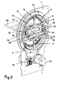
- the turning device has as a carrier a base plate 1, in which a turning ring 2 and a drive ring 3 are rotatably mounted about an axis 37.
- the turning ring 2 and the drive ring 3 are coaxial with each other and side by side and are each axially secured by retaining rings 4, 5, which are screwed to both sides of the base plate 1.
- the reversing ring 2 has a base plate 1 projecting ring 6 over which a drive belt 7 is placed. It is designed as a toothed belt, in which engages a gear 8, which sits on a shaft 9 of a drive motor 10.
- the drive motor 10 is advantageously a servomotor, which is fastened to the base plate 1. It lies at a distance from the securing rings 4, 5.
- the drive belt 7 is driven properly due to its positive engagement with the gear 8, so that the reversing ring 2 is reliably rotated in the turning process to be described.
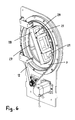
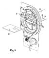
- the drive ring 3 also has a ring 11 ( Fig. 1 ), over which a drive belt 12 is placed and which projects beyond the other side of the base plate 1.
- the drive belt 12 is formed as a toothed belt and in engagement with a gear 13, which sits on a shaft 14 of a drive motor 15. It is advantageous a servo drive with which the drive ring 3 can be reliably rotated about its axis 37.
- the positive connection of the gear 13 with the drive belt 12 ensures that the drive ring 3 is reliably rotated.
- Fig. 1 and 2 shows the drive belts 7 and 12 for the turning ring 2 and the drive ring 3 on opposite sides of the base plate 1.
- the corresponding rings 6, 11 lead the drive belt 7, 12 and are on the retaining rings 4, 5 so far on that they safely from the drive belt 7, 12 can be detected.
- the outside of the rings 6, 11 is advantageously provided with a toothing, in which the drive belt 7, 12 formed as a toothed belt engage. In this way, a slip between the rings 6, 11 and the drive belt 7, 12 is prevented, so that the turning ring 2 and the drive ring 3 are properly rotated during the turning process. That's the way it is possible to achieve very high numbers of cycles with the turning device, without affecting the safety during the turning process.
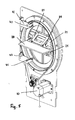
- the turning ring 2 is stiffened by transverse struts 16 to 19.
- the transverse struts 16, 17 each perpendicular to the transverse struts 18 and 19, which extend parallel to each other.
- In the region between these transverse struts 18, 19 are two shafts 20, which are parallel to each other and each carry at least one transport roller 21. In the exemplary embodiment sit on each shaft 20 at a distance from each other two transport rollers 21st
- each shaft 20 sits at the ends facing away from each other a gear 22.
- the shafts 20 are rotatably mounted in bearing parts 23, 24. They are mounted in recesses 25, 26 on the inside of the turning ring 2.
- the gears 22 engage in a spur gear, preferably a crown gear 27 of the drive ring 3 a. If the drive ring 3 is rotated about its axis, then the shafts 20 and thus the transport rollers 21 are rotated via the gears 22. Between the transport rollers 21, the product to be turned 28 is introduced.
- the transport rollers 21 may consist of elastically yielding material or even have only a coating consisting of elastic material. The introduced between the transport rollers 21 product 28 is then held securely by appropriate elastic deformation during the turning process.
- a receptacle 29 is attached, which receives the product to be turned 28 for the turning process.
- the receptacle 29 has two spaced-apart frame-shaped guide members 30, 31, between which the product to be turned 28 is pushed.
- the guide elements 30, 31 are provided with perforations 32, 33, so that the transport rollers 21 come into contact with the product 28.
- the guide elements 30, 31 are each secured to the transverse struts 18, 19 by holding elements 34, 35.
- the product 28 supplied by a feed device (not shown) is located in a transport plane 28 (FIG. Fig. 1 ) and is moved between the two guide elements 30, 31 of the receptacle 29. With this feeding device, the product is pushed so far between the guide elements 30, 31 until it comes into contact with the transport rollers 21.
- the drive motor 10 of the turning ring 2 is automatically started.
- the drive ring 3 is already rotated about its axis by the drive motor 15, while the feed device 28 feeds the product.
- the direction of rotation of the drive ring 3 is adjusted so that the product 28 is drawn into the receptacle 29 as soon as it is detected by the transport rollers 21.
- the reversing ring 2 and the drive ring 3 are driven by the respective drive motors 10, 15 so that the drive ring 3 rotates faster by that amount than the propulsion of the product 28, which it should have during the turning process.
- the rotational speeds of turning ring 2 and drive ring 3 are coordinated so that during the turning process, the transport rollers 21 further transport the product 28 in the receptacle 29 so that at the end of the turning process, the turned product 28 is picked up by a removal device and transported further in the turned position can be.
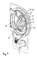
- Fig. 1 shows the product 28 still at a distance from the turning device.
- the feed device (not shown) transports the product 28 into the receptacle 29 until it is detected by the transport rollers 21 in the manner described ( Fig. 5 ).
- the drive motor 10 is turned on, whereby the turning ring 2 is rotated about the drive belt 7 about its axis.
- the Fig. 6 and 7 show intermediate positions of the turning ring 2 in this turning process.
- the drive ring 3 is constantly driven by the drive belt 12, whereby the shafts 20 of the turning ring 2 are rotated via the crown gear teeth 27 and the gears 22 engaging in them.
- the product is therefore continuously transported during the turning process in the receptacle 29 of the transport rollers 21.
- Fig. 8 shows the turning ring 2 after a 180 ° turn.
- the drive motor 10 is stopped, so that the reversing ring 2 stops in the position shown. In this position, the turned product 28 is not yet released from the transport rollers 21.
- the speed of the drive ring 3 is changed in this position by means of the drive motor 15 so that the turned product 28 is released from the transport rollers 21 only when a (not shown) transport device can take over the turned product 28.
- sensors 40, 41 are provided ( Fig. 5 ) monitoring the inlet and outlet of the products 28 in the turning device.
- the sensors 40, 41 which are, for example, light guides - photo switches or light barriers, are fastened to the base plate 1 by means of holding brackets 42, 43.
- the brackets 42, 43 are formed so that the sensors 40, 41 have no contact with the turning ring 2 and the drive ring 3.
- the sensors 40, 41 are placed as close as possible to the shafts 20 and the transport rollers 21 for optimum performance and evaluate the passing of the leading edge 44 and the trailing edge 36 of the product 28 (FIG. Fig. 9 ).
- the next product to be used 28 can be supplied in the manner described. Then a new turning cycle begins.
- the turned product 28 is on a Transport level 39, which is at the same height as the inlet-side transport plane 38.
- the axis of rotation 37 of the turning ring 2 and the drive ring 3 is equal to the two transport planes 38, 39 and extends in the transport direction of the product 28 (FIG. Fig. 1 ). This ensures that the product 28 is after the turning process in the amount of the output side transport plane 39.
- the product 28, without being turned can be transported from the transport plane 38 through the turning device to the transport plane 39.
- the two guide elements 30, 31 of the receptacle 29 are arranged in the starting position of the Wenderinges 2 so that the product 28 is transported into the receptacle 29.
- the drive ring 3 is rotatably driven in the described manner when the turning ring 2 is stationary, so that the transport rollers 21 transport the product 28 without turning through the turning device.
- the speed with which the products 28 are successively fed to the turning device is adjusted so that the time interval between the release of the turned product 28 and the feed of the product to be used is minimal. Since the reversing ring 2 and the drive ring 3 are rotatably driven independently of each other, this tuning can be made reliably with high precision. The turning device thus works perfectly with a very high number of cycles.
- the transport rollers 21 are always driven in the same direction, so that a reversal of the drive ring 3 is not required. Thereby, the cycle time for the delivery and the delivery of the products 28 can be kept very small.
- the reversing ring 2 is driven discontinuously in contrast to the drive ring 3. So that the product 28 can be transported into the receptacle 29 of the reversing ring 2, the reversing ring 2 must stand still. Only when the introduced into the receptacle 29 product 28 has been taken over by the transport rollers 21 and the feeder has released the product 28, the turning ring 2 is rotated by 180 °.
- the drive ring 3 is driven with the drive motor 15 at such a speed that the product 28 is always conveyed during the turning process of the transport rollers 21 so that the product at the end of the turning process is still held by the transport rollers 21 until the subsequent Transport device can take over the turned product 28. This ensures that the product is always held between the transport rollers 21 during the turning process, so that the turning operation can be carried out reliably.
- the turning device allows high speeds or high clock speeds.
- the turning device is characterized by a short and stable design. Since the reversing ring 2 and the drive ring 3 are driven independently of each other, there is also the possibility that the product 28 is transported through the receptacle 29 without a turning process taking place. In this way, with the turning device selectively depending on the application, the product can be turned or not turned.
- the receptacle 29 is located centrally in the reversing ring 2. As a result, the product 28 is before and after the turning process in the same plane, so that the transport plane for the product 28 does not have to be changed.
- the transport rollers 21 ensure in the manner described that the product 28 is not displaced during the turning process. This also eliminates an alignment process, as is the case with conventional turning devices.
- the turning device it is possible in a simple manner to turn the products 28 not only by 180 °, but, for example, only to rotate by 90 °.
- This is advantageous, for example, when the feed device is arranged in front of and the transport device behind the turning device at right angles to one another.
- the turning ring 2 is stopped in each case after a rotation of 90 °.
- the rotational speed of the drive ring 3 is then at the corresponding smaller angle of rotation matched the turning ring 2.
- One possible application is the placement of lying products or vice versa.
- the turning device can be easily installed in existing systems, where a turning of the product is required.
Landscapes
- Engineering & Computer Science (AREA)
- Mechanical Engineering (AREA)
- Attitude Control For Articles On Conveyors (AREA)
Abstract
Description
Die Erfindung betrifft eine Wendevorrichtung für flache Produkte aus Papier, Kunststoff und dergleichen nach dem Oberbegriff des Anspruches 1 sowie ein Verfahren zum Wenden von solchen flachen Produkten aus Papier, Kunststoff und dergleichen nach dem Oberbegriff des Anspruches 12.The invention relates to a turning device for flat products made of paper, plastic and the like according to the preamble of claim 1 and a method for turning such flat products of paper, plastic and the like according to the preamble of
Es sind Wendevorrichtungen bekannt, mit denen flache Produkte, wie beispielsweise Einzelblätter, gewendet werden. Die Wendevorrichtung befindet sich zwischen zwei Transportebenen, auf denen das Produkt zunächst der Wendevorrichtung zugeführt und nach dem Wendevorgang abgeführt wird. Das Produkt fährt in die Wendevorrichtung ein, wird angehalten und anschließend gewendet. Nach dem Wendevorgang verlässt das Produkt die Wendevorrichtung auf der anderen Transportebene, auf der es abgeführt wird. Diese Transportebene liegt auf einer a-nderen Höhe als die vor der Wendevorrichtung zur Zuführung der Produkte eingesetzte Transportebene. Im Einsatz solcher Einrichtungen kommt es vor, dass nicht alle Produkte gewendet werden müssen. In einem solchen Fall ist es notwendig, das Produkt vor oder nach der Wendevorrichtung durch eine Schwenkeinheit auf die jeweils andere Transportebene zu bringen. Darum ist ein sehr hoher mechanischer Aufwand erforderlich. Es werden vier Transportachsen mit entsprechendem Antrieb benötigt, wodurch sich größere zu bewegende Massen beim Wendevorgang, eine geringe Taktzahl und damit auch eine geringe Leistung der Einrichtung ergeben.Turning devices are known with which flat products, such as single sheets, are turned. The turning device is located between two transport planes, on which the product is first fed to the turning device and discharged after the turning process. The product enters the turning device, is stopped and then turned. After the turning process, the product leaves the turning device on the other transport plane on which it is discharged. This transport plane lies at a different height than the transport plane used before the turning device for feeding the products. In the use of such facilities, it may happen that not all products have to be turned. In such a case, it is necessary to bring the product before or after the turning device by a pivoting unit to the other transport plane. Therefore, a very high mechanical effort is required. There are four transport axes required with the corresponding drive, resulting in larger masses to be moved during the turning process, a low number of cycles and thus also a low performance of the device.
Es sind auch Wendevorrichtungen bekannt, die aus einem verschränkten Transportriementrieb bestehen. Das Produkt befindet sich zwischen den Transportriemen und wird über eine längere Strecke mit ihnen transportiert. Aufgrund der Verschränkung der Transportriemen wird hierbei das Produkt gewendet. Bei einer solchen Wendevorrichtung sind zwar hohe Taktzahlen möglich, jedoch besteht keine Möglichkeit, ein Produkt auch ohne Wenden durchlaufen zu lassen. Darüber hinaus sind die verschränkten Transportriementriebe für größere oder dickere Produkte wenig geeignet. Die Produkte können sich während des Transportes zwischen den Riemen verschieben und müssen nach dem Wendevorgang neu ausgerichtet werden. Zudem haben diese Wendevorrichtungen eine erhebliche Länge, so dass ein entsprechend großer Aufstellraum notwendig ist.There are also turning devices are known which consist of an entangled transport belt drive. The product is located between the Transport belt and is transported over a longer distance with them. Due to the entanglement of the transport belt here the product is turned. In such a turning device, although high cycle numbers are possible, but there is no way to run a product without turning. In addition, the entangled Transporttriementriebe for larger or thicker products are less suitable. The products may shift between the belts during transport and must be realigned after turning. In addition, these turning devices have a considerable length, so that a correspondingly large installation space is necessary.
Der Erfindung liegt die Aufgabe zugrunde, die gattungsgemäße Wendevorrichtung und das gattungsgemäße Verfahren so auszubilden, dass bei einfacher konstruktiver und platzsparender Bauweise hohe Transportgeschwindigkeiten bzw. hohe Taktzahlen beim Wendevorgang möglich sind, wobei es auch möglich sein soll, dass die Produkte durch die Wendevorrichtung laufen können, ohne dass sie gewendet werden.The invention has the object of providing the generic turning device and the generic method in such a way that in a simple constructive and space-saving design high transport speeds and high clock speeds during the turning process are possible, and it should also be possible that the products can run through the turning device without being turned around.
Diese Aufgabe wird bei der gattungsgemäßen Wendevorrichtung sowie dem gattungsgemäßen Verfahren erfindungsgemäß mit den kennzeichnenden Merkmalen des Anspruches 1 bzw. 12 gelöst.This object is achieved according to the invention in the generic turning device and the generic method with the characterizing features of
Bei der erfindungsgemäßen Wendevorrichtung liegt die Drehachse in Höhe der Transportebenen und verläuft in Transportrichtung. Darum befindet sich das Produkt nach dem Wendevorgang auf Höhe der zur Abführung des gewendeten Produktes vorgesehenen Transportebene, so dass das Produkt unmittelbar weitertransportiert werden kann. Zusatzeinrichtungen, um das gewendete Produkt auf die Höhe dieser Transportebene zu bringen, sind nicht erforderlich. Es ist auch möglich, das Produkt ohne einen Wendevorgang durch die Wendevorrichtung zu transportieren, da die beiden Transportebenen in Höhe der Drehachse der Wendevorrichtung liegen. Darum können die Produkte wahlweise bei ihrem Transport einem Wendevorgang unterzogen werden oder ohne Wenden durch die Wendevorrichtung transportiert werden. Mit der erfindungsgemäßen Wendevorrichtung ist es somit möglich, eine hohe Geschwindigkeit bzw. eine hohe Taktzahl zu erreichen und selektiv einen Wendevorgang ohne Umstellung der Transportebenen zu erreichen.In the turning device according to the invention, the axis of rotation is at the level of the transport planes and extends in the transport direction. Therefore, after the turning process, the product is at the level of the transport plane intended for the removal of the turned product, so that the product can be immediately transported further. Additional equipment to bring the turned product on the level of this transport level, are not required. It is also possible to transport the product without a turning process by the turning device, since the two transport planes are equal to the axis of rotation of the turning device. Therefore, the products can either be subjected to a turning process during their transport or transported without turning through the turning device become. With the turning device according to the invention, it is thus possible to achieve a high speed or a high number of cycles and to selectively achieve a turning operation without changing the transport planes.
Vorteilhaft ist die Aufnahme Teil eines Wenderings. Er zeichnet sich durch eine kompakte Bauform aus.Advantageously, the recording is part of a turning ring. It is characterized by a compact design.
Bei einer vorteilhaften Ausführungsform wird der Wendering durch einen Endlostrieb um seine Achse gedreht. Der Endlostrieb hat vorteilhaft einen Zahnriemen, mit dem ein schlupffreier Drehantrieb des Wenderinges sichergestellt ist.In an advantageous embodiment of the turning ring is rotated by a Endlostrieb about its axis. The endless drive advantageously has a toothed belt with which a slip-free rotary drive of the reversing ring is ensured.
Vorteilhaft ist der Wendering mit Transportrollen für das Produkt versehen. Mit ihnen kann das Produkt während des Wendevorganges zumindest festgehalten, vorzugsweise aber auch weitertransportiert werden.Advantageously, the turning ring is provided with transport rollers for the product. With them, the product can at least be held during the turning process, but preferably also be transported on.
Die Transportrollen sitzen bevorzugt auf zueinander parallelen Wellen, die ihrerseits im Wendering drehbar gelagert sind. Bei einer solchen Ausbildung kann das Produkt zwischen die Transportrollen transportiert und mit ihnen während des Wendevorganges festgehalten werden. Soll kein Wendevorgang durchgeführt werden, dann dienen die Transportrollen dazu, das Produkt ohne Wenden durch die Wendevorrichtung von der einen zur anderen Transportebene zu transportieren.The transport rollers preferably sit on mutually parallel shafts, which in turn are rotatably mounted in the turning ring. With such a design, the product can be transported between the transport rollers and held with them during the turning process. If no turning operation is to be performed, then the transport rollers serve to transport the product without turning through the turning device from one to the other transport plane.
Um die Wellen und damit die Transportrollen anzutreiben, ist der Antrieb der Wellen vorteilhaft von einem Antriebsring abgeleitet. Der Antriebsring trägt zur einer kompakten Bauform der Wendevorrichtung bei.In order to drive the shafts and thus the transport rollers, the drive of the shafts is advantageously derived from a drive ring. The drive ring contributes to a compact design of the turning device.
Vorteilhaft wird der Antriebsring durch einen Endlostrieb drehbar angetrieben. Ein solcher Endlostrieb hat vorteilhaft einen Zahnriemen, mit dem ein schlupffreier Antrieb des Antriebsringes gewährleistet ist.Advantageously, the drive ring is rotatably driven by a Endlostrieb. Such a endless drive advantageously has a toothed belt with which a slip-free drive of the drive ring is ensured.
Bei einer vorteilhaften Ausführungsform sind die Wellen des Wenderinges über ein Zahnradgetriebe mit dem Antriebsring antriebsverbunden. Über das Zahnradgetriebe können die Wellen des Wenderinges einfach drehbar angetrieben werden.In an advantageous embodiment, the waves of the turning ring are drive-connected to the drive ring via a gear transmission. About the gear transmission, the waves of the turning ring can be driven easily rotatable.
Das Zahnradgetriebe ist bei einer vorteilhaften Ausführungsform dadurch gebildet, dass auf den Wellen des Wenderinges Zahnräder sitzen, die in eine Stirnverzahnung des Antriebsringes eingreifen. Durch Drehen des Antriebsringes werden über dessen Stirnverzahnung die Zahnräder der Wellen angetrieben. Die Stirnverzahnung ist bevorzugt eine Kronenradverzahnung.The gear transmission is formed in an advantageous embodiment in that sitting on the shafts of the turning ring gears, which engage in a face gear of the drive ring. By turning the drive ring, the gears of the shafts are driven via the spur toothing. The spur gear is preferably a crown gear teeth.
Eine einfache und kompakte Bauform ergibt sich, wenn der Wendering und der Antriebsring koaxial zueinander liegen und/oder nebeneinander in einem Träger drehbar gelagert sind.A simple and compact design results when the turning ring and the drive ring are coaxial with each other and / or are rotatably supported side by side in a carrier.
Beim erfindungsgemäßen Verfahren wird das Produkt während des Wendevorganges in der Aufnahme so weitertransportiert, dass es am Ende des Wendevorganges in Höhe der Transportebene zum Abführen des gewendeten Produktes liegt. Dadurch kann das gewendete Produkt unmittelbar nach dem Wendevorgang weitertransportiert werden.In the method according to the invention, the product is transported during the turning process in the recording so that it is at the end of the turning process in height of the transport plane for discharging the turned product. As a result, the turned product can be transported immediately after the turning process.
Von Vorteil ist es, wenn der Transportweg des Produktes während des Wendevorganges kleiner ist als die in Transportrichtung gemessene Länge/Breite des Produktes. Dadurch befindet sich das Produkt am Ende des Wendevorganges noch in der Aufnahme der Wendevorrichtung. Der Transportweg kann auf diese Weise kurz gehalten werden.It is advantageous if the transport path of the product during the turning process is smaller than the length / width of the product measured in the transport direction. As a result, the product is still in the receptacle of the turning device at the end of the turning process. The transport can be kept short in this way.
Während des Wendevorganges wird das Produkt in vorteilhafter Weise dann zuverlässig gehalten, wenn es durch Transportrollen transportiert wird, zwischen denen das Produkt liegt. Außerdem kann durch die Transportrollen das Produkt auch ohne Wendevorgang zwischen den Transportrollen hindurch auf die nachfolgende Transportebene transportiert werden.During the turning process, the product is advantageously held reliably when it is transported by transport rollers, between which the product is located. In addition, the product can be transported by the transport rollers without turning operation between the transport rollers on the subsequent transport plane.
Bei einer erfindungsgemäßen Ausbildung werden die Transportrollen unabhängig vom Antrieb für den Wendevorgang angetrieben. Dadurch kann die Drehzahl der Transportrollen an die Drehzahl des Wenderinges einfach angepasst werden. So kann der Wendering still stehen, während die Transportrollen weiterhin angetrieben werden, um das Produkt ohne Wenden durch die Wendevorrichtung zu transportieren.In an embodiment of the invention, the transport rollers are driven independently of the drive for the turning process. As a result, the speed of the transport rollers can be easily adapted to the speed of the turning ring. Thus, the turning ring can stand still while the transport rollers continue to be driven to transport the product without turning through the turning device.
Weitere Merkmale der Erfindung ergeben sich aus den weiteren Ansprüchen, der Beschreibung und den Zeichnungen.Further features of the invention will become apparent from the other claims, the description and the drawings.
Die Erfindung wird anhand eines in den Zeichnungen dargestellten Ausführungsbeispieles näher erläutert. Es zeigen
- Fig. 1
- in perspektivischer Darstellung eine erfindungsgemäße Wendevorrichtung von der Einlaufseite aus,
- Fig. 2
- in perspektivischer Darstellung die erfindungsgemäße Wendevorrichtung von der Auslaufseite aus gesehen,
- Fig. 3
- in perspektivischer Darstellung einen Wendering mit Antrieb der erfindungsgemäßen Wendevorrichtung,
- Fig. 4
- in perspektivischer Darstellung einen Antriebsring mit Antrieb der erfindungsgemäßen Wendevorrichtung,
- Fig. 5 bis Fig. 9
- jeweils in perspektivischer Darstellung einen mit der erfindungsgemäßen Wendevorrichtung durchgeführten Wendevorgang.
- Fig. 1
- in a perspective view of a turning device according to the invention from the inlet side,
- Fig. 2
- in a perspective view of the turning device according to the invention seen from the outlet side,
- Fig. 3
- in a perspective view a turning ring with drive of the turning device according to the invention,
- Fig. 4
- a perspective view of a drive ring with drive the turning device according to the invention,
- Fig. 5 to Fig. 9
- in each case in perspective view a turning process carried out with the turning device according to the invention.
Die Wendevorrichtung dient dazu, flache Produkte aus Papier, Kunststoff und dergleichen, wie Einzelblätter, Briefumschläge, flache Stapel und dergleichen, zu wenden.The turning device serves to turn flat products of paper, plastic and the like, such as cut sheets, envelopes, flat piles and the like.
Die Wendevorrichtung hat als Träger eine Grundplatte 1, in welcher ein Wendering 2 und ein Antriebsring 3 um eine Achse 37 drehbar gelagert sind. Der Wendering 2 und der Antriebsring 3 liegen koaxial zueinander und nebeneinander und sind jeweils durch Sicherungsringe 4, 5 axial gesichert, die an beide Seiten der Grundplatte 1 angeschraubt sind. Der Wendering 2 hat einen über die Grundplatte 1 vorstehenden Ring 6, über den ein Antriebsriemen 7 gelegt ist. Er ist als Zahnriemen ausgebildet, in den ein Zahnrad 8 eingreift, das auf einer Welle 9 eines Antriebsmotors 10 sitzt. Der Antriebsmotor 10 ist vorteilhaft ein Servomotor, der an der Grundplatte 1 befestigt ist. Er liegt mit Abstand zu den Sicherungsringen 4, 5. Der Antriebsriemen 7 wird infolge seines Formschlusses mit dem Zahnrad 8 einwandfrei angetrieben, so dass der Wendering 2 beim noch zu beschreibenden Wendevorgang zuverlässig gedreht wird. Der Antriebsring 3 hat ebenfalls einen Ring 11 (
Wie sich aus den
Der Wendering 2 wird durch Querstreben 16 bis 19 versteift. Die Querstreben 16, 17 schließen jeweils rechtwinklig an die Querstreben 18 und 19 an, die parallel zueinander verlaufen. Im Bereich zwischen diesen Querstreben 18, 19 befinden sich zwei Wellen 20, die parallel zueinander liegen und jeweils wenigstens eine Transportrolle 21 tragen. Im Ausführungsbeispiel sitzen auf jeder Welle 20 mit Abstand voneinander zwei Transportrollen 21.The
Auf jeder Welle 20 sitzt an den voneinander abgewandten Enden jeweils ein Zahnrad 22. Die Wellen 20 sind in Lagerteilen 23, 24 drehbar gelagert. Sie sind in Vertiefungen 25, 26 an der Innenseite des Wenderinges 2 befestigt.On each
Die Zahnräder 22 greifen in eine Stirnverzahnung, vorzugsweise eine Kronenradverzahnung 27 des Antriebsringes 3 ein. Wird der Antriebsring 3 um seine Achse gedreht, dann werden über die Zahnräder 22 die Wellen 20 und damit die Transportrollen 21 gedreht. Zwischen die Transportrollen 21 wird das zu wendende Produkt 28 eingebracht. Die Transportrollen 21 können aus elastisch nachgiebigem Material bestehen oder auch lediglich einen aus elastischem Material bestehenden Überzug aufweisen. Das zwischen die Transportrollen 21 eingeführte Produkt 28 wird dann durch entsprechende elastische Verformung während des Wendevorganges sicher gehalten.The
An den beiden Querstreben 18, 19 ist eine Aufnahme 29 befestigt, die das zu wendende Produkt 28 für den Wendevorgang aufnimmt. Wie
Zu Beginn eines Wendevorganges befindet sich der Wendering 2 mit der Aufnahme 29 in der in
Der Wendering 2 und der Antriebsring 3 werden durch die jeweiligen Antriebsmotoren 10, 15 so angetrieben, dass der Antriebsring 3 um denjenigen Betrag schneller dreht als der Vortrieb des Produktes 28, den er während des Wendevorganges haben soll. Die Drehgeschwindigkeiten von Wendering 2 und Antriebsring 3 sind so aufeinander abgestimmt, dass während des Wendevorganges die Transportrollen 21 das Produkt 28 in der Aufnahme 29 weiter so transportieren, dass am Ende des Wendevorganges das gewendete Produkt 28 von einer Entnahmevorrichtung aufgenommen und in der gewendeten Lage weitertransportiert werden kann.The reversing
Während dieses Wendevorganges wird der Antriebsring 3 durch den Antriebsriemen 12 ständig angetrieben, wodurch über die Kronenradverzahnung 27 und die in sie eingreifenden Zahnräder 22 die Wellen 20 des Wenderinges 2 gedreht werden. Das Produkt wird darum während des Wendevorganges ständig in der Aufnahme 29 von den Transportrollen 21 weitertransportiert.During this turning operation, the
Um den Wendevorgang zu starten, den Transport des Produktes 28 während des Wendevorganges und die Übergabe des Produktes 28 an die Entnahmevorrichtung nach dem Wenden zu steuern, sind Sensoren 40, 41 vorgesehen (
Sobald die in Transportrichtung des gewendeten Produktes 28 hintere Kante 36 von den Transportrollen 21 freikommt (
Die Geschwindigkeit, mit der die Produkte 28 nacheinander der Wendevorrichtung zugeführt werden, ist so abgestimmt, dass der zeitliche Abstand zwischen der Freigabe des gewendeten Produktes 28 und der Zuführung des zu wendenden Produktes minimal ist. Da der Wendering 2 und der Antriebsring 3 unabhängig voneinander drehbar angetrieben werden, lässt sich diese Abstimmung mit hoher Präzision zuverlässig vornehmen. Die Wendevorrichtung arbeitet dadurch mit einer sehr hohen Taktzahl einwandfrei.The speed with which the
Die Transportrollen 21 werden stets in gleicher Richtung angetrieben, so dass eine Umsteuerung des Antriebsringes 3 nicht erforderlich ist. Dadurch kann die Taktzeit für die Abgabe und die Zuführung der Produkte 28 sehr klein gehalten werden. Der Wendering 2 wird im Unterschied zum Antriebsring 3 diskontinuierlich angetrieben. Damit das Produkt 28 in die Aufnahme 29 des Wenderinges 2 transportiert werden kann, muss der Wendering 2 still stehen. Erst wenn das in die Aufnahme 29 eingeführte Produkt 28 von den Transportrollen 21 übernommen worden ist und die Zuführvorrichtung das Produkt 28 freigegeben hat, wird der Wendering 2 um 180° gedreht. Der Antriebsring 3 wird mit dem Antriebsmotor 15 mit einer solchen Geschwindigkeit angetrieben, dass das Produkt 28 während des Wendevorganges stets von den Transportrollen 21 so weitergefördert wird, dass das Produkt am Ende des Wendevorganges noch von den Transportrollen 21 so lange gehalten wird, bis die nachfolgende Transportvorrichtung das gewendete Produkt 28 übernehmen kann. Somit ist sichergestellt, dass das Produkt während des Wendevorganges stets zwischen den Transportrollen 21 gehalten ist, so dass der Wendevorgang zuverlässig durchgeführt werden kann.The
Die Wendevorrichtung ermöglicht hohe Geschwindigkeiten bzw. hohe Taktzahlen. Dabei zeichnet sich die Wendevorrichtung durch eine kurze und stabile Bauform aus. Da der Wendering 2 und der Antriebsring 3 unabhängig voneinander angetrieben werden, besteht auch die Möglichkeit, dass das Produkt 28 durch die Aufnahme 29 transportiert wird, ohne dass ein Wendevorgang stattfindet. Auf diese Weise kann mit der Wendevorrichtung selektiv je nach Anwendungsfall das Produkt gewendet oder nicht gewendet werden. Die Aufnahme 29 befindet sich mittig im Wendering 2. Dadurch befindet sich das Produkt 28 vor und nach dem Wendevorgang in der gleichen Ebene, so dass die Transportebene für das Produkt 28 nicht umgestellt werden muss. Die Transportrollen 21 sorgen in der beschriebenen Weise dafür, dass das Produkt 28 während des Wendevorganges nicht verschoben wird. Dadurch entfällt auch ein Ausrichtvorgang, wie dies bei herkömmlichen Wendevorrichtungen der Fall ist.The turning device allows high speeds or high clock speeds. The turning device is characterized by a short and stable design. Since the reversing
Mit der Wendevorrichtung ist es in einfacher Weise möglich, die Produkte 28 nicht nur um 180° zu wenden, sondern beispielsweise nur um 90° zu drehen. Dies ist beispielsweise dann von Vorteil, wenn die Zuführvorrichtung vor und die Transportvorrichtung hinter der Wendevorrichtung in rechtem Winkel zueinander angeordnet sind. In diesem Falle wird der Wendering 2 jeweils nach einer Drehung um 90° angehalten. Die Drehgeschwindigkeit des Antriebsringes 3 wird dann auf den entsprechend kleineren Drehwinkel des Wenderinges 2 abgestimmt. Ein möglicher Anwendungsfall ist das Aufstellen von liegenden Produkten oder umgekehrt.With the turning device, it is possible in a simple manner to turn the
Die Wendevorrichtung lässt sich einfach in bestehende Anlagen einbauen, bei denen ein Wenden des Produktes erforderlich ist.The turning device can be easily installed in existing systems, where a turning of the product is required.
Claims (15)
dadurch gekennzeichnet, dass die Aufnahme (29) Teil eines Wenderinges (2) ist.Turning device according to claim 1,
characterized in that the receptacle (29) is part of a turning ring (2).
dadurch gekennzeichnet, dass der Wendering (2) durch einen Endlostrieb (7 bis 10) drehbar ist.Turning device according to claim 2,
characterized in that the turning ring (2) by a Endlostrieb (7 to 10) is rotatable.
dadurch gekennzeichnet, dass der Wendering (2) mit Transportrollen (21) für das Produkt (28) versehen ist.Turning device according to claim 2 or 3,
characterized in that the turning ring (2) is provided with transport rollers (21) for the product (28).
dadurch gekennzeichnet, dass die Transportrollen (21) auf zueinander parallelen Wellen (20) sitzen, die im Wendering (2) drehbar gelagert sind.Turning device according to claim 4,
characterized in that the transport rollers (21) sitting on mutually parallel shafts (20) which are rotatably mounted in the turning ring (2).
dadurch gekennzeichnet, dass der Antrieb der Wellen (20) von einem Antriebsring (3) abgeleitet ist.Turning device according to claim 5,
characterized in that the drive of the shafts (20) is derived from a drive ring (3).
dadurch gekennzeichnet, dass der Antriebsring (3) durch einen Endlostrieb (12 bis 15) drehbar ist.Turning device according to claim 6,
characterized in that the drive ring (3) by a Endlostrieb (12 to 15) is rotatable.
dadurch gekennzeichnet, dass die Wellen (20) des Wenderinges (2) über ein Zahnradgetriebe (22, 27) mit dem Antriebsring (3) antriebsverbunden sind.Turning device according to claim 6 or 7,
characterized in that the shafts (20) of the turning ring (2) are drive-connected via a gear transmission (22, 27) to the drive ring (3).
dadurch gekennzeichnet, dass auf den Wellen (20) des Wenderinges (2) Zahnräder (22) sitzen, die in eine Stirnverzahnung (27), vorzugsweise eine Kronenradverzahnung, des Antriebsringes (3) eingreifen.Turning device according to claim 8,
characterized in that on the shafts (20) of the turning ring (2) gear wheels (22) are seated, which engage in a spur toothing (27), preferably a crown gear, the drive ring (3).
dadurch gekennzeichnet, dass der Wendering (2) und der Antriebsring (3) koaxial zueinander liegen.Turning device according to one of claims 1 to 9,
characterized in that the turning ring (2) and the drive ring (3) are coaxial with each other.
dadurch gekennzeichnet, dass der Wendering (2) und der Antriebsring (3) nebeneinander in einem Träger (1) drehbar gelagert sind.Turning device according to one of claims 1 to 10,
characterized in that the turning ring (2) and the drive ring (3) side by side in a carrier (1) are rotatably mounted.
dadurch gekennzeichnet, dass der Transportweg des Produktes (28) während des Wendevorganges kleiner ist als die in Transportrichtung gemessene Länge/Breite des Produktes (28).Method according to claim 12,
characterized in that the transport path of the product (28) during the turning process is smaller than the length / width of the product (28) measured in the transport direction.
dadurch gekennzeichnet, dass das Produkt (28) durch Transportrollen (21) transportiert wird, zwischen denen das Produkt (28) liegt.Method according to claim 12 or 13,
characterized in that the product (28) is transported by transport rollers (21) between which the product (28) lies.
dadurch gekennzeichnet, dass die Transportrollen (21) unabhängig vom Antrieb (10) für den Wendevorgang angetrieben werden.Method, in particular according to one of claims 12 to 14,
characterized in that the transport rollers (21) are driven independently of the drive (10) for the turning operation.
Applications Claiming Priority (1)
| Application Number | Priority Date | Filing Date | Title |
|---|---|---|---|
| DE102012008504A DE102012008504A1 (en) | 2012-04-25 | 2012-04-25 | Turning device for flat products of paper, plastic and the like, as well as methods for turning such flat products |
Publications (1)
| Publication Number | Publication Date |
|---|---|
| EP2657166A2 true EP2657166A2 (en) | 2013-10-30 |
Family
ID=48190685
Family Applications (1)
| Application Number | Title | Priority Date | Filing Date |
|---|---|---|---|
| EP13002200.7A Withdrawn EP2657166A2 (en) | 2012-04-25 | 2013-04-25 | Turning device for flat products made of paper, plastic and the like and method for turning of such flat products |
Country Status (2)
| Country | Link |
|---|---|
| EP (1) | EP2657166A2 (en) |
| DE (1) | DE102012008504A1 (en) |
Cited By (4)
| Publication number | Priority date | Publication date | Assignee | Title |
|---|---|---|---|---|
| CN104891226A (en) * | 2015-06-01 | 2015-09-09 | 上海同韵环保能源科技有限公司 | Wind-power blade turnover device |
| CN105729213A (en) * | 2016-04-30 | 2016-07-06 | 临清兴和宏鑫机床有限公司 | Turnover mechanism |
| CN111807104A (en) * | 2020-07-14 | 2020-10-23 | 瑞安市方大信封机械有限公司 | Integrated envelope binding and transporting table |
| CN114193065A (en) * | 2021-12-29 | 2022-03-18 | 宁夏鑫中奥智能装备有限公司 | Special open linkage welding positioner for middle groove |
-
2012
- 2012-04-25 DE DE102012008504A patent/DE102012008504A1/en not_active Withdrawn
-
2013
- 2013-04-25 EP EP13002200.7A patent/EP2657166A2/en not_active Withdrawn
Non-Patent Citations (1)
| Title |
|---|
| None |
Cited By (6)
| Publication number | Priority date | Publication date | Assignee | Title |
|---|---|---|---|---|
| CN104891226A (en) * | 2015-06-01 | 2015-09-09 | 上海同韵环保能源科技有限公司 | Wind-power blade turnover device |
| CN105729213A (en) * | 2016-04-30 | 2016-07-06 | 临清兴和宏鑫机床有限公司 | Turnover mechanism |
| CN105729213B (en) * | 2016-04-30 | 2018-06-08 | 临清兴和宏鑫机床有限公司 | Switching mechanism |
| CN111807104A (en) * | 2020-07-14 | 2020-10-23 | 瑞安市方大信封机械有限公司 | Integrated envelope binding and transporting table |
| CN111807104B (en) * | 2020-07-14 | 2022-04-08 | 瑞安市方大信封机械有限公司 | Integrated envelope binding and transporting table |
| CN114193065A (en) * | 2021-12-29 | 2022-03-18 | 宁夏鑫中奥智能装备有限公司 | Special open linkage welding positioner for middle groove |
Also Published As
| Publication number | Publication date |
|---|---|
| DE102012008504A1 (en) | 2013-10-31 |
Similar Documents
| Publication | Publication Date | Title |
|---|---|---|
| EP2199240B1 (en) | Device for separating parts | |
| DE3911859A1 (en) | METHOD AND DEVICE FOR DIVIDING A CONTINUOUS SAUSAGE STRING COMING FROM A FILLING MACHINE INTO INDIVIDUAL SAUSAGES | |
| DE3420336A1 (en) | PAPER SHEET STORAGE DEVICE | |
| EP3400805A1 (en) | Device and method for transferring and lay sausages groups in a package | |
| DE1782864A1 (en) | DEVICE FOR TURNING CIGARETTES CONTINUOUSLY DELIVERED IN A ROW | |
| DE2401340C3 (en) | Wrapping device in a coin wrapping machine | |
| EP2657166A2 (en) | Turning device for flat products made of paper, plastic and the like and method for turning of such flat products | |
| DE3108044C2 (en) | Device for handling sheets of material | |
| DE2747799C2 (en) | ||
| EP0302376A3 (en) | Apparatus and method for sorting sheet-formed record carriers delivered by an office machine | |
| EP1084977A2 (en) | Method for transporting sheets and device for carrying out this method | |
| DE2164215C3 (en) | Device for transporting a web-shaped edge-perforated material | |
| DE3909373C2 (en) | ||
| EP2896490B1 (en) | Circular blade drive, in particular for bread cutting machines | |
| DD216422A5 (en) | DEVICE FOR THE ADDED FEEDING OF BLADES TO THE WRAPPING ROLL OF A BUEROOM MACHINE | |
| EP3186180B1 (en) | Stacking device for stacking value documents, method for stacking value documents with such a stacking device, and value documents processing device with such a stacking device | |
| DE3214457C2 (en) | ||
| DE102017128349A1 (en) | Edge processing arrangement | |
| DE2231088C3 (en) | Device for sorting and counting coins of various sizes | |
| DE1574639B2 (en) | DEVICE FOR ALIGNING A TAPE MOVABLE IN ONE DIRECTION OR TAPE SECTIONS MADE OF STICKY TIRE BUILDING MATERIAL IN RELATION TO A PLANE PARALLEL TO THE CONVEYOR DIRECTION | |
| DE102021125587B3 (en) | Device and method for aligning sausages | |
| EP0982253B1 (en) | Device for processing flexible and flat products | |
| DE2007368A1 (en) | Device for concertina-like folding of arches | |
| DE2318552A1 (en) | DEVICE TO PREVENT THE DEPLOYMENT OF PACKAGING MATERIAL IN COIN PACKAGING EQUIPMENT | |
| DE10335418B3 (en) | Collecting device for sheets supplied in succession has stop element in form of motorized rotating body with recess to hold front edge of sheet |
Legal Events
| Date | Code | Title | Description |
|---|---|---|---|
| PUAI | Public reference made under article 153(3) epc to a published international application that has entered the european phase |
Free format text: ORIGINAL CODE: 0009012 |
|
| AK | Designated contracting states |
Kind code of ref document: A2 Designated state(s): AL AT BE BG CH CY CZ DE DK EE ES FI FR GB GR HR HU IE IS IT LI LT LU LV MC MK MT NL NO PL PT RO RS SE SI SK SM TR |
|
| AX | Request for extension of the european patent |
Extension state: BA ME |
|
| STAA | Information on the status of an ep patent application or granted ep patent |
Free format text: STATUS: THE APPLICATION IS DEEMED TO BE WITHDRAWN |
|
| 18D | Application deemed to be withdrawn |
Effective date: 20151103 |