EP2652940B1 - Comprehension and intent-based content for augmented reality displays - Google Patents
Comprehension and intent-based content for augmented reality displays Download PDFInfo
- Publication number
- EP2652940B1 EP2652940B1 EP11849398.0A EP11849398A EP2652940B1 EP 2652940 B1 EP2652940 B1 EP 2652940B1 EP 11849398 A EP11849398 A EP 11849398A EP 2652940 B1 EP2652940 B1 EP 2652940B1
- Authority
- EP
- European Patent Office
- Prior art keywords
- user
- objects
- intent
- focal region
- interact
- Prior art date
- Legal status (The legal status is an assumption and is not a legal conclusion. Google has not performed a legal analysis and makes no representation as to the accuracy of the status listed.)
- Not-in-force
Links
Images


Classifications
-
- G—PHYSICS
- G06—COMPUTING OR CALCULATING; COUNTING
- G06F—ELECTRIC DIGITAL DATA PROCESSING
- G06F3/00—Input arrangements for transferring data to be processed into a form capable of being handled by the computer; Output arrangements for transferring data from processing unit to output unit, e.g. interface arrangements
- G06F3/01—Input arrangements or combined input and output arrangements for interaction between user and computer
- G06F3/011—Arrangements for interaction with the human body, e.g. for user immersion in virtual reality
- G06F3/013—Eye tracking input arrangements
-
- G—PHYSICS
- G02—OPTICS
- G02B—OPTICAL ELEMENTS, SYSTEMS OR APPARATUS
- G02B27/00—Optical systems or apparatus not provided for by any of the groups G02B1/00 - G02B26/00, G02B30/00
- G02B27/01—Head-up displays
-
- G—PHYSICS
- G02—OPTICS
- G02B—OPTICAL ELEMENTS, SYSTEMS OR APPARATUS
- G02B27/00—Optical systems or apparatus not provided for by any of the groups G02B1/00 - G02B26/00, G02B30/00
- G02B27/01—Head-up displays
- G02B27/017—Head mounted
-
- G—PHYSICS
- G06—COMPUTING OR CALCULATING; COUNTING
- G06F—ELECTRIC DIGITAL DATA PROCESSING
- G06F3/00—Input arrangements for transferring data to be processed into a form capable of being handled by the computer; Output arrangements for transferring data from processing unit to output unit, e.g. interface arrangements
- G06F3/01—Input arrangements or combined input and output arrangements for interaction between user and computer
- G06F3/017—Gesture based interaction, e.g. based on a set of recognized hand gestures
-
- G—PHYSICS
- G06—COMPUTING OR CALCULATING; COUNTING
- G06T—IMAGE DATA PROCESSING OR GENERATION, IN GENERAL
- G06T17/00—Three dimensional [3D] modelling, e.g. data description of 3D objects
-
- H—ELECTRICITY
- H04—ELECTRIC COMMUNICATION TECHNIQUE
- H04N—PICTORIAL COMMUNICATION, e.g. TELEVISION
- H04N21/00—Selective content distribution, e.g. interactive television or video on demand [VOD]
- H04N21/20—Servers specifically adapted for the distribution of content, e.g. VOD servers; Operations thereof
- H04N21/25—Management operations performed by the server for facilitating the content distribution or administrating data related to end-users or client devices, e.g. end-user or client device authentication, learning user preferences for recommending movies
- H04N21/258—Client or end-user data management, e.g. managing client capabilities, user preferences or demographics, processing of multiple end-users preferences to derive collaborative data
- H04N21/25866—Management of end-user data
- H04N21/25891—Management of end-user data being end-user preferences
-
- H—ELECTRICITY
- H04—ELECTRIC COMMUNICATION TECHNIQUE
- H04N—PICTORIAL COMMUNICATION, e.g. TELEVISION
- H04N21/00—Selective content distribution, e.g. interactive television or video on demand [VOD]
- H04N21/40—Client devices specifically adapted for the reception of or interaction with content, e.g. set-top-box [STB]; Operations thereof
- H04N21/47—End-user applications
- H04N21/472—End-user interface for requesting content, additional data or services; End-user interface for interacting with content, e.g. for content reservation or setting reminders, for requesting event notification, for manipulating displayed content
- H04N21/47205—End-user interface for requesting content, additional data or services; End-user interface for interacting with content, e.g. for content reservation or setting reminders, for requesting event notification, for manipulating displayed content for manipulating displayed content, e.g. interacting with MPEG-4 objects, editing locally
-
- H—ELECTRICITY
- H04—ELECTRIC COMMUNICATION TECHNIQUE
- H04N—PICTORIAL COMMUNICATION, e.g. TELEVISION
- H04N21/00—Selective content distribution, e.g. interactive television or video on demand [VOD]
- H04N21/40—Client devices specifically adapted for the reception of or interaction with content, e.g. set-top-box [STB]; Operations thereof
- H04N21/47—End-user applications
- H04N21/472—End-user interface for requesting content, additional data or services; End-user interface for interacting with content, e.g. for content reservation or setting reminders, for requesting event notification, for manipulating displayed content
- H04N21/4722—End-user interface for requesting content, additional data or services; End-user interface for interacting with content, e.g. for content reservation or setting reminders, for requesting event notification, for manipulating displayed content for requesting additional data associated with the content
- H04N21/4725—End-user interface for requesting content, additional data or services; End-user interface for interacting with content, e.g. for content reservation or setting reminders, for requesting event notification, for manipulating displayed content for requesting additional data associated with the content using interactive regions of the image, e.g. hot spots
-
- H—ELECTRICITY
- H04—ELECTRIC COMMUNICATION TECHNIQUE
- H04N—PICTORIAL COMMUNICATION, e.g. TELEVISION
- H04N5/00—Details of television systems
- H04N5/222—Studio circuitry; Studio devices; Studio equipment
- H04N5/262—Studio circuits, e.g. for mixing, switching-over, change of character of image, other special effects ; Cameras specially adapted for the electronic generation of special effects
-
- G—PHYSICS
- G02—OPTICS
- G02B—OPTICAL ELEMENTS, SYSTEMS OR APPARATUS
- G02B27/00—Optical systems or apparatus not provided for by any of the groups G02B1/00 - G02B26/00, G02B30/00
- G02B27/01—Head-up displays
- G02B27/0101—Head-up displays characterised by optical features
- G02B2027/014—Head-up displays characterised by optical features comprising information/image processing systems
-
- G—PHYSICS
- G02—OPTICS
- G02B—OPTICAL ELEMENTS, SYSTEMS OR APPARATUS
- G02B27/00—Optical systems or apparatus not provided for by any of the groups G02B1/00 - G02B26/00, G02B30/00
- G02B27/01—Head-up displays
- G02B27/017—Head mounted
- G02B2027/0178—Eyeglass type
-
- G—PHYSICS
- G02—OPTICS
- G02B—OPTICAL ELEMENTS, SYSTEMS OR APPARATUS
- G02B27/00—Optical systems or apparatus not provided for by any of the groups G02B1/00 - G02B26/00, G02B30/00
- G02B27/01—Head-up displays
- G02B27/0179—Display position adjusting means not related to the information to be displayed
- G02B2027/0187—Display position adjusting means not related to the information to be displayed slaved to motion of at least a part of the body of the user, e.g. head, eye
Definitions
- Augmented reality is a technology that allows virtual imagery to be mixed with a real world physical environment or space.
- near eye displays are worn by users to view the mixed imagery of virtual and real objects.
- near-eye displays use a combination of optics and stereopsis to focus virtual imagery within the space.
- the virtual imagery that is displayed to a user via a near-eye display device may include virtual images or objects that include highly detailed graphics.
- near-eye display devices being generally mobile, tend to be limited on computational resources and may not present the virtual imagery accurately to the user.
- a user wearing a near-eye display device is typically presented with large amounts of information that the user is not necessarily interested in looking at.
- WO 2007/085303 A1 shows a head-mounted display with a camera connected thereto.
- the camera detects this looking direction and the corresponding image of this part of the environment.
- a presentation unit may be adapted for overlaying secondary information with primary data to the user. Thus, an impression or illusion may be given to the user that the physical primary data is perceived simultaneously with the virtual secondary data.
- US 2010/0238161 A1 discloses a computer-aided system for 360° heads up display of safety/mission critical data.
- the user can look in a direction of an object and either by activating a control button or by speech recognition selects the object. This can cause the object to be highlighted and the system can then provide further information on the selected object.
- the user can also remove or add layers of occlusions by selecting and requesting a layer to be removed. As an example, if a pilot is looking at an aircraft wing, and the pilot wants to look at what is behind the wing, the pilot can select a function to turn off wing occlusion and have video feed of a gimbaled zoom camera positioned so that the wing does not occlude it.
- US 2010/056274 A1 discloses a method, apparatus, and computer program that reduces bandwidth requirements in mobile video and gaming applications by tracking a gaze fixation point of a user on a video image at a remote location.
- a method and system that enhances a user's experience when using a near eye display device, such as a see-through display device or a head mounted display device by optimizing the visualized information displayed to the user.
- the visualized information is optimized by prioritizing the visualized information displayed to the user.
- the visualized information is prioritized by determining the user's inferred or expressed_intent to interact with one or more objects in the user's environment.
- an optimized image is generated based on the prioritized visual information.
- the optimized image visually enhances the appearance of objects that the user intends to interact with in the user's environment and/or diminishes the appearance of objects that the user does not intend to interact with in the user's environment.
- the user's intent is determined by analyzing the user's eye movements, and intensity of the user's gaze on the objects in the user's environment.
- the user's intent is automatically determined based on user specific information related to the user.
- the optimized image reduces the computational resources required by the head mounted display device while processing and presenting visualized information to a user.
- the user's comprehension of visualized information in the user's environment is increased by automatically enhancing one or more objects in the user's environment.
- an optimized image that visually enhances the appearance of the one or more objects that increase the user's comprehension is generated.
- the user's intent to interact with the one or more visually enhanced objects in the optimized image is determined.
- a method for generating an optimized image based on user intent in an augmented reality system includes determining objects or people of interest in a scene the user is viewing using a see-through display device.
- the field of view of the user is determined.
- the field of view is a portion of the space or environment that the user is looking at.
- the focal region of the user within the field of view is determined.
- the user's intent to interact with one or more objects or people in the focal region of the user is determined.
- an optimized image is generated for the user based on the user's intent.
- the optimized image is displayed to the user, via the see-through display device.
- a user looks at a scene via a near eye display device such as a head mounted display device.
- the user's field of view which is a portion of the environment or space that the user may observe, is determined. Objects of possible interest within the field of view are also determined.
- the field of view may include a user's focal region, or what the user is actually focusing on within the field of view.
- the user's focal region is determined by tracking the position of the user's eyes in the field of view. The user's inferred or expressed intent to interact with one or more objects in the user's focal region is then determined.
- the user's intent to interact with one or more objects in the user's focal region is determined by detecting the user's eye movement patterns in the user's focal region and determining the intensity of the user's gaze on one or more objects being viewed by the user in the user's focal region.
- the user's intent to interact with one or more objects in the user's focal region is automatically determined by accessing user-specific information related to the user.
- the user's intent to interact with one or more objects in the user's focal region is determined by prompting the user to specify intent to interact with one or more objects via a user physical action, such as a voice input, keyboard entry, a touch sensitive device or a gesture.
- a user's inferred or expressed intent to interact with one or more objects is determined by the environment and other factors, such as the time of day, location, and external inputs.
- An optimized image is generated based on the user's need or intent.
- the optimized image is displayed to the user, via the head mounted display device.
- the optimized image may include one or more of an enhanced appearance of objects in the user's focal region, a diminished appearance of objects outside the user's focal region but within the user's field of view and augmented content such as virtual images, or virtual objects related to the objects that the user intends to interact with, in the user's focal region. Any one or more of such enhancements may be used in combination.
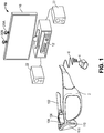
- Fig. 1 is a block diagram depicting example components of one embodiment of a system 10 for generating an optimized image based on user intent.
- System 10 includes a see-through display device as a near-eye, head mounted display device 2 in communication with processing unit 4 via wire 6.
- head mounted display device 2 communicates with processing unit 4 via wireless communication.
- Head mounted display device 2 which in one embodiment is in the shape of glasses, is worn on the head of a user so that the user can see through a display and thereby have an actual direct view of the space in front of the user.
- actual and direct view refers to the ability to see the real world objects directly with the human eye, rather than seeing created image representations of the objects. For example, looking through glass at a room allows a user to have an actual direct view of the room, while viewing a video of a room on a television is not an actual direct view of the room. More details of the head mounted display device 2 are provided below.
- processing unit 4 is worn by the user and includes much of the computing power used to operate head mounted display device 2.
- Processing unit 4 communicates wirelessly (e.g., WiFi, Bluetooth, infra-red, or other wireless communication means) to one or more hub computing systems 12.
- Hub computing system 12 may be a computer, a gaming system or console, or the like.
- the hub computing system 12 may include hardware components and/or software components such that hub computing system 12 may be used to execute applications such as gaming applications, non-gaming applications, or the like.
- hub computing system 12 may include a processor such as a standardized processor, a specialized processor, a microprocessor, or the like that may execute instructions stored on a processor readable storage device for performing the processes described herein.
- Hub computing system 12 further includes one or more capture devices, such as capture devices 20A and 20B.
- capture devices 20A and 20B are pointed in different directions so that they capture different portions of the room. It may be advantageous that the field of view of the two capture devices slightly overlap so that hub computing system 12 can understand how the fields of view of the capture devices relate to each other. In this manner, multiple capture devices can be used to view an entire room (or other space).
- one capture device can be used if the capture device can be panned during operation so that over time the field of view is viewed by the capture device.
- Non-overlapping capture devices can also determine fields of view in relation to another known point, such as the position of the head mounted display worn by a user.
- Capture devices 20A and 20B may be, for example, cameras that visually monitor one or more users and the surrounding space such that gestures and/or movements performed by the one or more users, as well as the structure of the surrounding space, may be captured, analyzed, and tracked to perform one or more controls or actions within the application and/or animate an avatar or on-screen character.
- Hub computing system 12 may be connected to an audiovisual device 16 such as a television, a monitor, a high-definition television (HDTV), or the like that may provide game or application visuals.
- an audiovisual device 16 such as a television, a monitor, a high-definition television (HDTV), or the like that may provide game or application visuals.
- hub computing system 12 may include a video adapter such as a graphics card and/or an audio adapter such as a sound card that may provide audiovisual signals associated with the game application, non-game application, etc.
- the audiovisual device 16 may receive the audiovisual signals from hub computing system 12 and may then output the game or application visuals and/or audio associated with the audiovisual signals.
- the audiovisual device 16 may be connected to hub computing system 12 via, for example, an S-Video cable, a coaxial cable, an HDMI cable, a DVI cable, a VGA cable, component video cable, RCA cables, etc.
- audiovisual device 16 includes internal speakers.
- audiovisual device 16, a separate stereo or hub computing system 12 is connected to external speakers 22.
- Hub computing device 10, with capture devices 20A and 20B may be used to recognize, analyze, and/or track human (and other types of) targets.
- a user wearing head mounted display device 2 may be tracked using the capture devices 20A and 20B such that the gestures and/or movements of the user may be captured to animate an avatar or on-screen character and/or may be interpreted as controls that may be used to affect the application being executed by hub computing system 12.
- system 10 generates an optimized image for the user based on determining the user's intent to interact with one or more objects in the user's environment.
- the optimized image may include an enhanced appearance of objects that the user intends to interact with, a diminished appearance of objects that the user does not intend to interact with, or both.
- the optimized image is displayed to the user, via the head mounted display device 2.
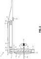
- Fig. 2 depicts a top view of a portion of head mounted display device 2, including a portion of the frame that includes temple 102 and nose bridge 104. Only the right side of head mounted display device 2 is depicted.
- a microphone 110 for recording sounds and transmitting that audio data to processing unit 4, as described below.
- At the front of head mounted display device 2 is room facing video camera 113 that can capture video and still images. Those images are transmitted to processing unit 4, as described below.
- a portion of the frame of head mounted display device 2 will surround a display (that includes one or more lenses). In order to show the components of head mounted display device 2, a portion of the frame surrounding the display is not depicted.
- the display includes a light guide optical element 112, opacity filter 114, see-through lens 116 and see-through lens 118.
- opacity filter 114 is behind and aligned with see-through lens 116
- lightguide optical element 112 is behind and aligned with opacity filter 114
- see-through lens 118 is behind and aligned with lightguide optical element 112. See-through lenses 116 and 118 are standard lenses used in eye glasses and can be made to any prescription (including no prescription).
- see-through lenses 116 and 118 can be replaced by a variable prescription lens.
- head mounted display device 2 will include only one see-through lens or no see-through lenses.
- a prescription lens can go inside light guide optical element 112.
- Opacity filter 114 filters out natural light (either on a per pixel basis or uniformly) to enhance the contrast of the virtual imagery.
- Light guide optical element 112 channels artificial light to the eye. More details of the opacity filter 114 and light guide optical element 112 is provided below. In alternative embodiments, an opacity filter 114 may not be utilized.
- an image source which (in one embodiment) includes micro display assembly 120 for projecting a virtual image and lens 122 for directing images from micro display 120 into light guide optical element 112.
- lens 122 is a collimating lens.
- Control circuits 136 provide various electronics that support the other components of head mounted display device 2. More details of control circuits 136 are provided below with respect to Fig. 3 .
- ear phones 130 Inside, or mounted to temple 102, are ear phones 130, inertial sensors 132 and temperature sensor 138.
- inertial sensors 132 include a three axis magnetometer 132A, three axis gyro 132B and three axis accelerometer 132C (See Fig. 3 ).
- the inertial sensors are for sensing position, orientation, and sudden accelerations of head mounted display device 2.
- Micro display 120 projects an image through lens 122.
- image generation technologies can be used to implement micro display 120.
- micro display 120 can be implemented in using a transmissive projection technology where the light source is modulated by optically active material, backlit with white light. These technologies are usually implemented using LCD type displays with powerful backlights and high optical energy densities.
- Micro display 120 can also be implemented using a reflective technology for which external light is reflected and modulated by an optically active material. The illumination is forward lit by either a white source or RGB source, depending on the technology.
- DGP digital light processing
- LCOS liquid crystal on silicon
- Mirasol® display technology from Qualcomm, inc.
- micro display 120 can be implemented using an emissive technology where light is generated by the display.
- a PicoPTM display engine from Microvision, Inc. emits a laser signal with a micro mirror steering either onto a tiny screen that acts as a transmissive element or beamed directly into the eye (e.g., laser).
- Light guide optical element 112 transmits light from micro display 120 to the eye 140 of the user wearing head mounted display device 2. Light guide optical element 112 also allows light from in front of the head mounted display device 2 to be transmitted through light guide optical element 112 to eye 140, as depicted by arrow 142, thereby allowing the user to have an actual direct view of the space in front of head mounted display device 2 in addition to receiving a virtual image from micro display 120. Thus, the walls of light guide optical element 112 are see-through.
- Light guide optical element 112 includes a first reflecting surface 124 (e.g., a mirror or other surface). Light from micro display 120 passes through lens 122 and becomes incident on reflecting surface 124.
- the reflecting surface 124 reflects the incident light from the micro display 120 such that light is trapped inside a planar, substrate comprising light guide optical element 112 by internal reflection. After several reflections off the surfaces of the substrate, the trapped light waves reach an array of selectively reflecting surfaces 126. Note that only one of the five surfaces is labeled 126 to prevent over-crowding of the drawing. Reflecting surfaces 126 couple the light waves incident upon those reflecting surfaces out of the substrate into the eye 140 of the user. As different light rays will travel and bounce off the inside of the substrate at different angles, the different rays will hit the various reflecting surface 126 at different angles. Therefore, different light rays will be reflected out of the substrate by different ones of the reflecting surfaces.
- each eye will have its own light guide optical element 112.
- each eye can have its own micro display 120 that can display the same image in both eyes or different images in the two eyes.
- Opacity filter 114 which is aligned with light guide optical element 112, selectively blocks natural light, either uniformly or on a per-pixel basis, from passing through light guide optical element 112.
- the opacity filter can be a see-through LCD panel, electro chromic film, or similar device which is capable of serving as an opacity filter.
- a see-through LCD panel can be obtained by removing various layers of substrate, backlight and diffusers from a conventional LCD.
- the LCD panel can include one or more light-transmissive LCD chips which allow light to pass through the liquid crystal. Such chips are used in LCD projectors, for instance.
- Opacity filter 114 can include a dense grid of pixels, where the light transmissivity of each pixel is individually controllable between minimum and maximum transmissivities. While a transmissivity range of 0-100% is ideal, more limited ranges are also acceptable. As an example, a monochrome LCD panel with no more than two polarizing filters is sufficient to provide an opacity range of about 50% to 90% per pixel, up to the resolution of the LCD. At the minimum of 50%, the lens will have a slightly tinted appearance, which is tolerable. 100% transmissivity represents a perfectly clear lens.
- An "alpha" scale can be defined from 0-100%, where 0% allows no light to pass and 100% allows all light to pass. The value of alpha can be set for each pixel by the opacity filter control circuit 224 described below.
- a mask of alpha values can be used from a rendering pipeline, after z-buffering with proxies for real-world objects.
- the system When the system renders a scene for the augmented reality display, it takes note of which real-world objects are in front of which virtual objects. If a virtual object is in front of a real-world object, then the opacity should be on for the coverage area of the virtual object. If the virtual is (virtually) behind a real-world object, then the opacity should be off, as well as any color for that pixel, so the user will only see the real-world object for that corresponding area (a pixel or more in size) of real light.
- opacity filter can be rendered in color, such as with a color LCD or with other displays such as organic LEDs, to provide a wide field of view. More details of an opacity filter are provided in U.S. Patent Application No. 12/887,426 , "Opacity Filter For See-Through Mounted Display," filed on September 21, 2010.
- An opacity filter such as an LCD has generally not been used with a see-through lens as described herein because at this near distance to the eye it can be out of focus. However, in some cases, this result can be desirable.
- a user sees the virtual image with crisp color graphics via the normal HMD display using additive color, which is designed to be in focus.
- the LCD panel is placed "behind" this display such that a fuzzy black border surrounds any virtual content, making it as opaque as desired.
- the system converts the flaw of natural blurring to expediently obtain the feature of anti-aliasing and bandwidth reduction. These are a natural result of using a lower-resolution and out-of-focus image. There is an effective smoothing of the digitally-sampled image.
- Any digital image is subject to aliasing, where the discrete nature of the sampling causes errors against the naturally analog and continuous signal, around the wavelengths of light. Smoothing means visually closer to the ideal analog signal. Although information lost to the low resolution is not recovered, the resulting errors are less noticeable.
- the display and the opacity filter are rendered simultaneously and are calibrated to a user's precise position in space to compensate for angle-offset issues. Eye tracking can be employed to compute the correct image offset at the extremities of the viewing field.
- a temporal or spatial fade in the amount of opacity can be used in the opacity filter.
- a temporal or spatial fade in the virtual image can be used.
- a temporal fade in the amount of opacity of the opacity filter corresponds to a temporal fade in the virtual image.
- a spatial fade in the amount of opacity of the opacity filter corresponds to a spatial fade in the virtual image.
- an increased opacity is provided for the pixels of the opacity filter which are behind the virtual image, from the perspective of the identified location of the user's eye.
- the pixels behind the virtual image are darkened so that light from a corresponding portion of the real world scene is blocked from reaching the user's eyes.
- This allows the virtual image to be realistic and represent a full range of colors and intensities.
- power consumption by the augmented reality emitter is reduced since the virtual image can be provided at a lower intensity. Without the opacity filter, the virtual image would need to be provided at a sufficiently high intensity which is brighter than the corresponding portion of the real world scene, for the virtual image to be distinct and not transparent.
- the pixels which follow the closed perimeter of virtual image are darkened, along with pixels within the perimeter. It can be desirable to provide some overlap so that some pixels which are just outside the perimeter and surround the perimeter are also darkened (at the same level of darkness or less dark than pixels inside the perimeter). These pixels just outside the perimeter can provide a fade (e.g., a gradual transition in opacity) from the darkness inside the perimeter to full amount of opacity outside the perimeter.
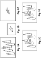
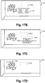
- Fig. 2A depicts an example real-world scene of a forest that is visible to a human eye looking through head mounted display device 2.
- Fig. 2B depicts a virtual image, which in this case is a dolphin.
- Fig. 2C depicts an example configuration of an opacity filter based on a shape of the virtual image of Fig. 2B .
- the opacity filter provides a darkened region of increased opacity where the dolphin will be rendered.
- An increased opacity generally refers to a darkening of pixels which can include allowing less light to pass through.
- FIG. 2D depicts the example image which is seen by a user and is the result of projecting the virtual image of the dolphin into the user's vision and using the opacity filter to remove light for the pixels corresponding to the position of the virtual image of the dolphin.
- the background is not visible through the dolphin.
- Fig. 2E shows the inserting of the virtual image into the real image without using the opacity filter. As can be seen, the real background can be seen through the virtual image of the dolphin.
- Head mounted display device 2 also includes a system for tracking the position of the user's eyes. As will be explained below, the system will track the user's position and orientation so that the system can determine the field of view of the user. However, a human will not perceive everything in front of them. Instead, a user's eyes will be directed at a subset of the environment. Therefore, in one embodiment, the system will include technology for tracking the position of the user's eyes in order to refine the measurement of the field of view of the user.
- head mounted display device 2 includes eye tracking assembly 134 (see Fig. 2 ), which will include an eye tracking illumination device 134A and eye tracking camera 134B (see Fig. 3 ).
- eye tracking illumination source 134A includes one or more infrared (IR) emitters, which emit IR light toward the eye.
- Eye tracking camera 134B includes one or more cameras that sense the reflected IR light.
- the position of the pupil can be identified by known imaging techniques which detects the reflection of the cornea. For example, see U.S. patent 7,401,920 , entitled “Head Mounted Eye Tracking and Display System", issued July 22, 2008 to Kranz et al. Such a technique can locate a position of the center of the eye relative to the tracking camera.
- eye tracking involves obtaining an image of the eye and using computer vision techniques to determine the location of the pupil within the eye socket.
- eye tracking camera may be an alternative form of tracking camera using any motion based image of the eye to detect position, with or without an illumination source.
- the system will use four IR LEDs and four IR photo detectors in rectangular arrangement so that there is one IR LED and IR photo detector at each corner of the lens of head mounted display device 2. Light from the LEDs reflect off the eyes. The amount of infrared light detected at each of the four IR photo detectors determines the pupil direction. That is, the amount of white versus black in the eye will determine the amount of light reflected off the eye for that particular photo detector. Thus, the photo detector will have a measure of the amount of white or black in the eye. From the four samples, the system can determine the direction of the eye.
- FIG. 2 shows one assembly with one IR emitter, the structure of Fig. 2 can be adjusted to have four IR transmitters and/or four IR sensors. More or less than four IR transmitters and/or four IR sensors can also be used.
- Another embodiment for tracking the direction of the eyes is based on charge tracking. This concept is based on the observation that a retina carries a measurable positive charge and the cornea has a negative charge. Sensors are mounted by the user's ears (near earphones 130) to detect the electrical potential while the eyes move around and effectively read out what the eyes are doing in real time. Other embodiments for tracking eyes, such as a small camera mounted on the inside of the glasses, can also be used.
- detectors may be included on the head mounted display device 2.
- detectors may include, without limitation, SONAR, LIDAR, Structured Light, and/or Time of Flight distance detectors positioned to detect information that a wearer of the device may be viewing.
- Fig. 2 only shows half of the head mounted display device 2.
- a full head mounted display device would include another set of see through lenses, another opacity filter, another light guide optical element, another micro display 136, another lens 122, room facing camera, eye tracking assembly, micro display, earphones, and temperature sensor. Additional details of a head mounted display 2 are illustrated in United States Patent Application Serial No. 12/905952 entitled Fusing Virtual Content Into Real Content, Filed October 15, 2010.
- Fig. 3 is a block diagram depicting the various components of head mounted display device 2.
- Fig. 4 is a block diagram describing the various components of processing unit 4.
- Head mounted display device 2 the components of which are depicted in Fig. 3 , are used to display an optimized image to the user, based on determining the user's intent to interact with one or more objects in the user's environment. Additionally, the head mounted display device components of Fig. 3 include many sensors that track various conditions. Head mounted display device 2 will receive instructions about the virtual image from processing unit 4 and will provide the sensor information back to processing unit 4.
- Processing unit 4, the components of which are depicted in Fig. 3 will receive the sensory information from head mounted display device 2 and also from hub computing device 12 (See Fig. 1 ). Based on that information, processing unit 4 will determine where and when to provide a virtual image to the user and send instructions accordingly to the head mounted display device of Fig. 3 .
- Fig. 3 shows the control circuit 200 in communication with the power management circuit 202.
- Control circuit 200 includes processor 210, memory controller 212 in communication with memory 214 (e.g., D-RAM), camera interface 216, camera buffer 218, display driver 220, display formatter 222, timing generator 226, display out interface 228, and display in interface 230.
- memory 214 e.g., D-RAM
- control circuit 200 all of components of control circuit 200 are in communication with each other via dedicated lines or one or more buses. In another embodiment, each of the components of control circuit 200 is in communication with processor 210.
- Camera interface 216 provides an interface to the two room facing cameras 113 and stores images received from the room facing cameras in camera buffer 218.
- Display driver 220 will drive micro display 120.
- Display formatter 222 provides information, about the virtual image being displayed on micro display 120, to opacity control circuit 224, which controls opacity filter 114.
- Timing generator 226 is used to provide timing data for the system.
- Display out interface 228 is a buffer for providing images from room facing cameras 113 to the processing unit 4.
- Display in 230 is a buffer for receiving images such as a virtual image to be displayed on micro display 120.
- Display out 228 and display in 230 communicate with band interface 232 which is an interface to processing unit 4.
- Power management circuit 202 includes voltage regulator 234, eye tracking illumination driver 236, audio DAC and amplifier 238, microphone preamplifier audio ADC 240, temperature sensor interface 242 and clock generator 244.
- Voltage regulator 234 receives power from processing unit 4 via band interface 232 and provides that power to the other components of head mounted display device 2.
- Eye tracking illumination driver 236 provides the IR light source for eye tracking illumination 134A, as described above.
- Audio DAC and amplifier 238 receive the audio information from earphones 130.
- Microphone preamplifier and audio ADC 240 provide an interface for microphone 110.
- Temperature sensor interface 242 is an interface for temperature sensor 138.
- Power management unit 202 also provides power and receives data back from three axis magnetometer 132A, three axis gyro 132B and three axis accelerometer 132C.
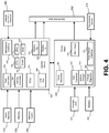
- Fig. 4 is a block diagram describing the various components of processing unit 4.
- Control circuit 304 includes a central processing unit (CPU) 320, graphics processing unit (GPU) 322, cache 324, RAM 326, memory control 328 in communication with memory 330 (e.g., D-RAM), flash memory controller 332 in communication with flash memory 334 (or other type of non-volatile storage), display out buffer 336 in communication with head mounted display device 2 via band interface 302 and band interface 232, display in buffer 338 in communication with head mounted display device 2 via band interface 302 and band interface 232, microphone interface 340 in communication with an external microphone connector 342 for connecting to a microphone, PCI express interface for connecting to a wireless communication device 346, and USB port(s) 348.
- CPU central processing unit
- GPU graphics processing unit
- RAM random access memory
- memory control 328 in communication with memory 330 (e.g., D-RAM)
- flash memory controller 332 in communication with flash memory 334 (or other type of non-volatile
- wireless communication device 346 can include a Wi-Fi enabled communication device, BlueTooth communication device, infrared communication device, etc.
- the USB port can be used to dock the processing unit 4 to hub computing device 12 in order to load data or software onto processing unit 4, as well as charge processing unit 4.
- CPU 320 and GPU 322 are the main workhorses for determining where, when and how to insert virtual images into the view of the user. More details are provided below.
- Power management circuit 306 includes clock generator 360, analog to digital converter 362, battery charger 364, voltage regulator 366, head mounted display power source 376, and temperature sensor interface 372 in communication with temperature sensor 374 (located on the wrist band of processing unit 4).
- Analog to digital converter 362 is connected to a charging jack 370 for receiving an AC supply and creating a DC supply for the system.
- Voltage regulator 366 is in communication with battery 368 for supplying power to the system.
- Battery charger 364 is used to charge battery 368 (via voltage regulator 366) upon receiving power from charging jack 370.
- HMD power source 376 provides power to the head mounted display device 2.
- the above-described system will be configured to insert a virtual image into the field of view of a user so that the virtual image replaces the view of a real world object.
- the virtual image can be inserted without replacing the image of a real world object.
- the virtual image will be adjusted to match the appropriate orientation, size and shape based on the object being replaced or the environment for which the image is being inserted into.
- the virtual image can be adjusted to include reflectivity and shadows.
- head mounted display device 12, processing unit 4 and hub computing device 12 work together as each of the devices includes a subset of sensors that are used to obtain the data for determining where, when and how to insert the virtual images.
- hub computing device 12 will create a model of the environment that the user is in and track various moving objects in that environment. In an alternative embodiment, object and users of interest in the environment are determined by other means. In addition, hub computing device 12 tracks the field of view of the head mounted display device 2 by tracking the position and orientation of head mounted display device 2. The model and the tracking information are provided from hub computing device 12 to processing unit 4. Sensor information obtained by head mounted display device 2 is transmitted to processing unit 4. Processing unit 4 then uses additional sensor information it receives from head mounted display device 2 to refine the field of view of the user and provide instructions to head mounted display device 2 on how, where and when to insert the virtual image.
- Fig. 5 illustrates an example embodiment of hub computing system 12 with a capture device.
- capture devoices 20A and 20B are the same structure, therefore, Fig. 5 only shows capture device 20A.
- capture device 20A may be configured to capture video with depth information including a depth image that may include depth values via any suitable technique including, for example, time-of-flight, structured light, stereo image, or the like.
- the capture device 20A may organize the depth information into "Z layers," or layers that may be perpendicular to a Z axis extending from the depth camera along its line of sight.
- capture device 20A may include a camera component 423.
- camera component 423 may be or may include a depth camera that may capture a depth image of a scene.
- the depth image may include a two-dimensional (2-D) pixel area of the captured scene where each pixel in the 2-D pixel area may represent a depth value such as a distance in, for example, centimeters, millimeters, or the like of an object in the captured scene from the camera.
- Camera component 23 may include an infra-red (IR) light component 425, a three-dimensional (3-D) camera 426, and an RGB (visual image) camera 428 that may be used to capture the depth image of a scene.
- IR infra-red
- 3-D three-dimensional
- RGB visual image
- the IR light component 425 of the capture device 20A may emit an infrared light onto the scene and may then use sensors (in some embodiments, including sensors not shown) to detect the backscattered light from the surface of one or more targets and objects in the scene using, for example, the 3-D camera 426 and/or the RGB camera 428.
- pulsed infrared light may be used such that the time between an outgoing light pulse and a corresponding incoming light pulse may be measured and used to determine a physical distance from the capture device 20A to a particular location on the targets or objects in the scene. Additionally, in other example embodiments, the phase of the outgoing light wave may be compared to the phase of the incoming light wave to determine a phase shift. The phase shift may then be used to determine a physical distance from the capture device to a particular location on the targets or objects.
- time-of-flight analysis may be used to indirectly determine a physical distance from the capture device 20A to a particular location on the targets or objects by analyzing the intensity of the reflected beam of light over time via various techniques including, for example, shuttered light pulse imaging.
- capture device 20A may use a structured light to capture depth information.
- patterned light i.e., light displayed as a known pattern such as grid pattern, a stripe pattern, or different pattern
- the pattern may become deformed in response.
- Such a deformation of the pattern may be captured by, for example, the 3-D camera 426 and/or the RGB camera 428 (and/or other sensor) and may then be analyzed to determine a physical distance from the capture device to a particular location on the targets or objects.
- the IR Light component 425 is displaced from the cameras 425 and 426 so triangulation can be used to determined distance from cameras 425 and 426.
- the capture device 20A will include a dedicated IR sensor to sense the IR light, or a sensor with an IR filter.
- the capture device 20A may include two or more physically separated cameras that may view a scene from different angles to obtain visual stereo data that may be resolved to generate depth information.
- Other types of depth image sensors can also be used to create a depth image.
- the capture device 20A may further include a microphone 430, which includes a transducer or sensor that may receive and convert sound into an electrical signal. Microphone 430 may be used to receive audio signals that may also be provided by hub computing system 12.
- the capture device 20A may further include a processor 432 that may be in communication with the image camera component 423.
- Processor 432 may include a standardized processor, a specialized processor, a microprocessor, or the like that may execute instructions including, for example, instructions for receiving a depth image, generating the appropriate data format (e.g., frame) and transmitting the data to hub computing system 12.
- Capture device 20A may further include a memory 434 that may store the instructions that are executed by processor 432, images or frames of images captured by the 3-D camera and/or RGB camera, or any other suitable information, images, or the like.
- memory 434 may include random access memory (RAM), read only memory (ROM), cache, flash memory, a hard disk, or any other suitable storage component.
- RAM random access memory
- ROM read only memory
- cache flash memory
- hard disk or any other suitable storage component.
- memory 434 may be a separate component in communication with the image capture component 423 and processor 432.
- the memory 434 may be integrated into processor 432 and/or the image capture component 422.
- Capture devices 20A and 20B are in communication with hub computing system 12 via a communication link 436.
- the communication link 436 may be a wired connection including, for example, a USB connection, a Firewire connection, an Ethernet cable connection, or the like and/or a wireless connection such as a wireless 802.1 lb, g, a, or n connection.
- hub computing system 12 may provide a clock to capture device 20A that may be used to determine when to capture, for example, a scene via the communication link 436.
- the capture device 20A provides the depth information and visual (e.g., RGB) images captured by, for example, the 3-D camera 426 and/or the RGB camera 428 to hub computing system 12 via the communication link 436.
- RGB visual
- the depth images and visual images are transmitted at 30 frames per second; however, other frame rates can be used.
- Hub computing system 12 may then create and use a model, depth information, and captured images to, for example, control an application such as a game or word processor and/or animate an avatar or on-screen character.
- Hub computing system 12 includes depth image processing and skeletal tracking module 450, which uses the depth images to track one or more persons detectable by the depth camera function of capture device 20A.
- Depth image processing and skeletal tracking module 450 provides the tracking information to application 453, which can be a video game, productivity application, communications application or other software application etc.
- the audio data and visual image data is also provided to application 452 and depth image processing and skeletal tracking module 450.
- Application 452 provides the tracking information, audio data and visual image data to recognizer engine 454.
- recognizer engine 454 receives the tracking information directly from depth image processing and skeletal tracking module 450 and receives the audio data and visual image data directly from capture devices 20A and 20B.
- Recognizer engine 454 is associated with a collection of filters 460, 462, 464, ..., 466 each comprising information concerning a gesture, action or condition that may be performed by any person or object detectable by capture device 20A or 20B.
- the data from capture device 20A may be processed by filters 460, 462, 464, ..., 466 to identify when a user or group of users has performed one or more gestures or other actions.
- Those gestures may be associated with various controls, objects or conditions of application 452.
- hub computing system 12 may use the recognizer engine 454, with the filters, to interpret and track movement of objects (including people).
- Capture devices 20A and 20B provide RGB images (or visual images in other formats or color spaces) and depth images to hub computing system 12.
- the depth image may be a plurality of observed pixels where each observed pixel has an observed depth value.
- the depth image may include a two-dimensional (2-D) pixel area of the captured scene where each pixel in the 2-D pixel area may have a depth value such as distance of an object in the captured scene from the capture device.
- Hub computing system 12 will use the RGB images and depth images to track a user's or object's movements. For example, the system will track a skeleton of a person using the depth images. There are many methods that can be used to track the skeleton of a person using depth images.
- Patent Applications U.S. Patent Application 12/475,308 , "Device for Identifying and Tracking Multiple Humans Over Time,” filed on May 29, 2009; U.S. Patent Application 12/696,282 , “Visual Based Identity Tracking,” filed on January 29, 2010; U.S. Patent Application 12/641,788 , “Motion Detection Using Depth Images,” filed on December 18, 2009; and U.S. Patent Application 12/575,388 , “Human Tracking System,” filed on October 7, 2009.
- Recognizer engine 454 includes multiple filters 460, 462, 464, ..., 466 to determine a gesture or action.
- a filter comprises information defining a gesture, action or condition along with parameters, or metadata, for that gesture, action or condition. For instance, a throw, which comprises motion of one of the hands from behind the rear of the body to past the front of the body, may be implemented as a gesture comprising information representing the movement of one of the hands of the user from behind the rear of the body to past the front of the body, as that movement would be captured by the depth camera. Parameters may then be set for that gesture.
- a parameter may be a threshold velocity that the hand has to reach, a distance the hand travels (either absolute, or relative to the size of the user as a whole), and a confidence rating by the recognizer engine that the gesture occurred.
- These parameters for the gesture may vary between applications, between contexts of a single application, or within one context of one application over time.
- Filters may be modular or interchangeable.
- a filter has a number of inputs (each of those inputs having a type) and a number of outputs (each of those outputs having a type).
- a first filter may be replaced with a second filter that has the same number and types of inputs and outputs as the first filter without altering any other aspect of the recognizer engine architecture. For instance, there may be a first filter for driving that takes as input skeletal data and outputs a confidence that the gesture associated with the filter is occurring and an angle of steering.
- a filter need not have a parameter. For instance, a "user height" filter that returns the user's height may not allow for any parameters that may be tuned.
- An alternate "user height” filter may have tunable parameters - such as to whether to account for a user's footwear, hairstyle, headwear and posture in determining the user's height.
- Inputs to a filter may comprise things such as joint data about a user's joint position, angles formed by the bones that meet at the joint, RGB color data from the scene, and the rate of change of an aspect of the user.
- Outputs from a filter may comprise things such as the confidence that a given gesture is being made, the speed at which a gesture motion is made, and a time at which a gesture motion is made.
- Recognizer engine 454 may have a base recognizer engine that provides functionality to the filters.
- the functionality that recognizer engine 454 implements includes an input-over-time archive that tracks recognized gestures and other input, a Hidden Markov Model implementation (where the modeled system is assumed to be a Markov process - one where a present state encapsulates any past state information used to determine a future state, so no other past state information must be maintained for this purpose - with unknown parameters, and hidden parameters are determined from the observable data), as well as other functionality used to solve particular instances of gesture recognition.
- Filters 460, 462, 464, ..., 466 are loaded and implemented on top of the recognizer engine 454 and can utilize services provided by recognizer engine 454 to all filters 460, 462, 464, ..., 466.
- recognizer engine 454 receives data to determine whether it meets the requirements of any filter 460, 462, 464, ..., 466. Since these provided services, such as parsing the input, are provided once by recognizer engine 454 rather than by each filter 460, 462, 464, ..., 466, such a service need only be processed once in a period of time as opposed to once per filter for that period, so the processing used to determine gestures is reduced.
- Application 452 may use the filters 460, 462, 464, ..., 466 provided with the recognizer engine 454, or it may provide its own filter, which plugs in to recognizer engine 454.
- all filters have a common interface to enable this plug-in characteristic. Further, all filters may utilize parameters, so a single gesture tool below may be used to debug and tune the entire filter system.
- recognizer engine 454 More information about recognizer engine 454 can be found in U.S. Patent Application 12/422,661 , "Gesture Recognizer System Architecture,” filed on April 13, 2009. More information about recognizing gestures can be found in U.S. Patent Application 12/391,150 , “Standard Gestures,” filed on February 23,2009; and U.S. Patent Application 12/474,655 , “Gesture Tool” filed on May 29, 2009.
- computing system 12 includes a user profile database 470 that includes user-specific information related to one or more users interacting with hub computing system 12.
- the user-specific information includes information related to a user such as the user's expressed preferences, the user's friends' list, the user's preferred activities, a list of the user's reminders, the user's social groups, the user's current location, the user's past intents to interact with objects in the user's environment and other user created content, such as the user's photos, images and recorded videos.
- the user-specific information may be obtained from one or more data sources such as the user's social networking sites, address book, email data, Instant Messaging data, user profiles or other sources on the Internet. In one approach, and as will be discussed in detail below, the user-specific information is utilized to automatically determine the user's intent to interact with one or more objects in the user's environment.
- Fig. 6 illustrates an example embodiment of a computing system that may be used to implement hub computing system 12.
- the multimedia console 500 has a central processing unit (CPU) 501 having a level 1 cache 502, a level 2 cache 504, and a flash ROM (Read Only Memory) 506.
- the level 1 cache 502 and a level 2 cache 504 temporarily store data and hence reduce the number of memory access cycles, thereby improving processing speed and throughput.
- CPU 501 may be provided having more than one core, and thus, additional level 1 and level 2 caches 502 and 504.
- the flash ROM 506 may store executable code that is loaded during an initial phase of a boot process when the multimedia console 500 is powered on.
- a graphics processing unit (GPU) 508 and a video encoder/video codec (coder/decoder) 514 form a video processing pipeline for high speed and high resolution graphics processing. Data is carried from the graphics processing unit 508 to the video encoder/video codec 514 via a bus. The video processing pipeline outputs data to an A/V (audio/video) port 540 for transmission to a television or other display.
- a memory controller 510 is connected to the GPU 508 to facilitate processor access to various types of memory 512, such as, but not limited to, a RAM (Random Access Memory).
- the multimedia console 500 includes an I/O controller 520, a system management controller 522, an audio processing unit 523, a network interface 524, a first USB host controller 526, a second USB controller 528 and a front panel I/O subassembly 530 that are preferably implemented on a module 518.
- the USB controllers 526 and 528 serve as hosts for peripheral controllers 542(1)-542(2), a wireless adapter 548, and an external memory device 546 (e.g., flash memory, external CD/DVD ROM drive, removable media, etc.).
- the network interface 524 and/or wireless adapter 548 provide access to a network (e.g., the Internet, home network, etc.) and may be any of a wide variety of various wired or wireless adapter components including an Ethernet card, a modem, a Bluetooth module, a cable modem, and the like.
- a network e.g., the Internet, home network, etc.
- wired or wireless adapter components including an Ethernet card, a modem, a Bluetooth module, a cable modem, and the like.
- System memory 543 is provided to store application data that is loaded during the boot process.
- a media drive 544 is provided and may comprise a DVD/CD drive, Blu-Ray drive, hard disk drive, or other removable media drive, etc.
- the media drive 144 may be internal or external to the multimedia console 500.
- Application data may be accessed via the media drive 544 for execution, playback, etc. by the multimedia console 500.
- the media drive 544 is connected to the I/O controller 520 via a bus, such as a Serial ATA bus or other high speed connection (e.g., IEEE 1394).
- the system management controller 522 provides a variety of service functions related to assuring availability of the multimedia console 500.
- the audio processing unit 523 and an audio codec 532 form a corresponding audio processing pipeline with high fidelity and stereo processing. Audio data is carried between the audio processing unit 523 and the audio codec 532 via a communication link.
- the audio processing pipeline outputs data to the A/V port 540 for reproduction by an external audio user or device having audio capabilities.
- the front panel I/O subassembly 530 supports the functionality of the power button 550 and the eject button 552, as well as any LEDs (light emitting diodes) or other indicators exposed on the outer surface of the multimedia console 100.
- a system power supply module 536 provides power to the components of the multimedia console 100.
- a fan 538 cools the circuitry within the multimedia console 500.
- the CPU 501, GPU 508, memory controller 510, and various other components within the multimedia console 500 are interconnected via one or more buses, including serial and parallel buses, a memory bus, a peripheral bus, and a processor or local bus using any of a variety of bus architectures.
- bus architectures can include a Peripheral Component Interconnects (PCI) bus, PCI-Express bus, etc.
- application data may be loaded from the system memory 543 into memory 512 and/or caches 502, 504 and executed on the CPU 501.
- the application may present a graphical user interface that provides a consistent user experience when navigating to different media types available on the multimedia console 500.
- applications and/or other media contained within the media drive 544 may be launched or played from the media drive 544 to provide additional functionalities to the multimedia console 500.
- the multimedia console 500 may be operated as a standalone system by simply connecting the system to a television or other display. In this standalone mode, the multimedia console 500 allows one or more users to interact with the system, watch movies, or listen to music. However, with the integration of broadband connectivity made available through the network interface 524 or the wireless adapter 548, the multimedia console 500 may further be operated as a participant in a larger network community. Additionally, multimedia console 500 can communicate with processing unit 4 via wireless adaptor 548.
- a set amount of hardware resources are reserved for system use by the multimedia console operating system. These resources may include a reservation of memory, CPU and GPU cycle, networking bandwidth, etc. Because these resources are reserved at system boot time, the reserved resources do not exist from the application's view.
- the memory reservation preferably is large enough to contain the launch kernel, concurrent system applications and drivers.
- the CPU reservation is preferably constant such that if the reserved CPU usage is not used by the system applications, an idle thread will consume any unused cycles.
- lightweight messages generated by the system applications are displayed by using a GPU interrupt to schedule code to render popup into an overlay.
- the amount of memory required for an overlay depends on the overlay area size and the overlay preferably scales with screen resolution. Where a full user interface is used by the concurrent system application, it is preferable to use a resolution independent of application resolution. A scaler may be used to set this resolution such that the need to change frequency and cause a TV resync is eliminated.
- multimedia console 500 boots and system resources are reserved, concurrent system applications execute to provide system functionalities.
- the system functionalities are encapsulated in a set of system applications that execute within the reserved system resources described above.
- the operating system kernel identifies threads that are system application threads versus gaming application threads.
- the system applications are preferably scheduled to run on the CPU 501 at predetermined times and intervals in order to provide a consistent system resource view to the application. The scheduling is to minimize cache disruption for the gaming application running on the console.
- a multimedia console application manager controls the gaming application audio level (e.g., mute, attenuate) when system applications are active.
- Optional input devices are shared by gaming applications and system applications.
- the input devices are not reserved resources, but are to be switched between system applications and the gaming application such that each will have a focus of the device.
- the application manager preferably controls the switching of input stream, without knowing the gaming application's knowledge and a driver maintains state information regarding focus switches.
- Capture devices 20A and 20B may define additional input devices for the console 500 via USB controller 526 or other interface.
- hub computing system 12 can be implemented using other hardware architectures. No one hardware architecture is required.
- Fig. 1 depicts one head mounted display device 2 and processing unit 4 (collectively referred to as a mobile display device) in communication with one hub computing device 12 (referred to as a hub).
- a mobile display device in communication with one hub computing device 12 (referred to as a hub).
- multiple mobile display devices can be in communication with a single hub.
- Each of the mobile display devices will communicate with the hub using wireless communication, as described above.
- the hub will generate the model of the environment and provide that model to all of the mobile display devices in communication with the hub.
- the hub can track the location and orientation of the mobile display devices and of the moving objects in the room, and then transfer that information to each of the mobile display devices.
- a system could include multiple hubs, with each hub including one or more mobile display devices.
- the hubs can communicate with each other directly or via the Internet (or other networks).
- Fig. 7 shows hubs 560, 562 and 564.
- Hub 560 communicates directly to hub 562.
- Hub 560 communicates to hub 564 via the Internet.
- Hub 560 communicated with mobile display devices 570, 572, ..., 574.
- Hub 562 communicates with mobile display device 578, 580, ..., 582.
- Hub 564 communicates with mobile display device 584, 586, ..., 588.
- Each of the mobile display devices communicate with their respective hub via wireless communication as discussed above.
- each of the hubs can provide a portion of the model of the environments, or one hub can create the model for the other hubs.
- Each of the hubs will track a subset of moving objects and share that information with the other hubs, which will in turn share the information with the appropriate mobile display devices.
- Sensor information for the mobile display devices will be provided to their respective hubs and then shared to the other hubs for eventual sharing to the other mobile display devices.
- information shared between hubs can include skeleton tracking, information about the models, various states of applications, and other tracking.
- the information communicated between the hubs and their respective mobile display devices include tracking information of moving objects, the state and physics updates for the world models, geometry and texture information, video and audio, and other information used to perform the operations described herein.
- Fig. 8 describes one embodiment of a process for optimizing the display of visualized information that is presented to a user of a head mounted display device.
- the system 10 is configured.
- an application e.g., application 452 of Fig. 5
- an application running on hub computing system 12 will indicate that augmented content (such as a particular virtual image or a virtual object) is to be inserted into the scene as part of a video game or other process.
- objects of interest in the user's environment will be determined. In one embodiment, this may be performed by creating a three dimensional model of the user's space as outlined in steps 602 - 606.
- the system will create a volumetric model of the space for which head mounted display device 2 is located.
- hub computing device 12 will use depth images from one or more depth cameras to create a three dimensional model of the environment or scene in which head mounted display device 2 is located.
- that model is segmented into one or more objects. For example, if hub computing device 12 creates a three dimensional model of a room, that room is likely to have multiple objects in it. Examples of objects that can be in a room include persons, chairs, tables, couches, etc.
- Step 604 includes determining distinct objects from each other.
- the system will identify the objects. For example, hub computing device 12 may identify that a particular object is a table and another object is a chair.
- step 605 may be performed by any number of means.
- sensors may be embedded in one or more objects or individuals in the room. Sensors which emit a detectable signal identifying the object of interest or providing additional information such as the type of object and the level of interest one might have in the object relative to a specific application may be used to identify objects in the user's environment.
- other sensor technologies may be used to identify objects within the range of either the capture device disclosed above, other sensor devices employing other distance detection sensor technologies (such as SONAR, LIDAR, Structured Light, and/or Time of Flight distance detectors) positioned in the environment, or on the head mounted display device, can all be used to provide possible focal objects and their shape.
- Another alternative is to use one or more of the above described depth cameras to perform a stereo reconstruction of the environment, one frame at a time.
- objects may themselves emit light pulses directed to the head mounted display to and indicate to the display that the object is of interest and that the portion of the display including the object should be highlighted.
- step 608 of Fig. 8 the system determines the field of view of the user based on the model or the above techniques. That is, the system determines a portion of the environment or space the user is looking at.
- step 608 may be performed using hub computing device 12, processing unit 4 and head mounted display device 2.
- hub computing device 12 will track the user and the head mounted display device 2 in order to provide a preliminary determination of location and orientation of head mounted display device 2.
- Sensors on the head mounted display device 2 will be used to refine the determined orientation.
- the inertial sensors 34 described above, can be used to refine the orientation of head mounted display device 2.
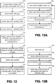
- the eye tracking process described below can be used to identify a subset of the initially determined field of view that corresponds to where in particular a user is looking otherwise known as the user's focal region or depth focus in the field of view. More details will be described below with respect to Figs. 12, 13A and 13B .
- the system determines the user's current focal region within the user's field of view.
- eye tracking processing based on data captured by the eye tracking camera 134 for each eye, can provide the current focal region of the user. For example, the convergence between the pupils with data indicating the face position of the user can be used to triangulate to a focal point on a focal curve, the Horopter, from which the focal region, the Panum's fusion area, can be calculated.
- the Panum's fusion area is the area of single vision for binocular stereopsis used by the human eyes.
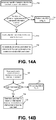
- step 612 the processing unit 4 alone or in cooperation with the hub computing device 12 (under the control of software) determines the user's intent to interact with one or more objects in the user's focal region.
- step 614 under the control of software, the processing unit 4 alone or in cooperation with the hub computing device 12 generates an optimized image and displays the optimized image to the user based on the user's intent to interact with the one or more objects.
- step 616 the user of head mounted display device 2 interacts with an application running on hub computing device 12 (or another computing device) based on the optimized image displayed in the head mounted display device 2.
- the processing steps (608-616) of Fig. 8 can be performed continuously during operation of the system such that the user's field of view and focal region are updated as the user moves his or her head, the user's intent to interact with one or more objects in the user's focal region is determined and an optimized image is displayed to the user based on the user's intent.
- Each of the steps 604-614 are described in more detail below.
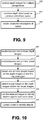
- Fig. 9 describes one embodiment of a process for creating a model of the user's space.
- the process of Fig. 9 is one example implementation of step 602 of Fig. 8 .
- hub computing system 12 receives one or more depth images for multiple perspectives, such as those shown in Fig. 1 , of the environment that head mounted display device is in.
- hub computing device 12 can obtain depth images from multiple depth cameras or multiple depth images from the same camera by pointing the camera in different directions or using a depth camera with a lens that allows a full view of the environment or space for which a model will be built.
- depth data from the various depth images are combined based on a common coordinate system. For example, if this system receives depth images from multiple cameras, the system will correlate the two images to have a common coordinate system (e.g., line up the images).
- a volumetric description of the space is created using the depth data.
- Fig. 10 is a flowchart describing one embodiment of a process for segmenting the model of the space into objects.
- the process of Fig. 10 is one example implementation of step 604 of Fig. 8 .
- the system will receive one or more depth images from one or more depth cameras as discussed above. Alternatively, the system can access one or more depth images that it has already received.
- the system will receive one or more visual images from the cameras described above. Alternatively, the system can access one or more visual images already received.
- hub computing system will detect one or more people based on the depth images and/or visual images. For example, the system will recognize one or more skeletons.
- hub computing device will detect edges within the model based on the depth images and/or the visual images.
- hub computing device will use the detected edges to identify distinct objects from each other. For example, it is assumed that edges are boundaries between objects.
- the model created using the process of Fig. 9 will be updated to show which portions of the model are associated with different objects.
- Fig. 11A is a flowchart describing one embodiment of a process for identifying objects.
- the process of Fig. 1A1 is one example implementation of step 606 of Fig. 8 .
- hub computing device 12 will match identified people to user identities.
- user profiles may include visual images that can be matched to the images of detected objects received by the capture devices.
- a user's profile can describe features of the person which can be matched based on the depth images or visual images.
- users may log into the system and hub computing device 12 can use the login process to identify a particular user and track that user throughout the interaction described herein.
- hub computing device 12 will access the database of shapes.
- hub computing device will match as many objects in the model to the shapes in the database.
- those shapes that are unmatched will be highlighted and displayed to the user (e.g., using monitor 16).
- hub computing device 12 will receive user input that identifies each (or a subset) of the shapes highlighted. For example, the user can use a keyboard, mouse, speech input, or other type of input to indicate what each unidentified shape is.
- the database of shapes is updated based on the user input in step 648.
- the model of the environment created in step 602, and updated in step 636 is further updated by adding metadata for each of the objects.
- the metadata identifies the object. For example the metadata may indicate that the particular object is a round shiny table, John Doe, green leather couch, etc.
- Fig. 11B is a flowchart describing one embodiment of a process for updating the model created by the process of Fig. 8 in response to moving objects (e.g., a moving person or other type of object).
- the system determines that an object is moving. For example, the system will continuously receive depth images. If the depth images change over time, then an object is moving. If no moving object is detected, then the system will continue to receive depth images and continue to look for moving objects.
- step 654 the system will identify the object that is moving.
- Frame differencing or any of various tracking technologies can be used to recognize the moving object and correlate the recognized object to one of the objects identified in step 606 of Fig. 8 .
- Some objects will change shape when moving. For example, a human may change shape as the human walks or runs.
- step 658 the new shape of the moving object is identified and stored.
- step 660 the model of the space that was previously created is updated based on the new position and shape of the moving object.
- the process of Fig. 11B can be performed by processing unit 4 of hub computing device 12.
- Fig. 12 is a flowchart describing one embodiment of a process for determining the field of view of a user, which is an example implementation of step 608 of Fig. 8 , and for determining the user's focal region, which is an example implementation of step 610 of Fig. 8 .
- the process of Fig. 12 relies on information from the hub computing device 12 and the eye tracking technology described above.
- Fig. 13A is a flowchart describing one embodiment of a process performed by the hub computing system to provide tracking information used in the process of Fig. 12.
- Fig. 13B is a flowchart describing one embodiment of a process for tracking an eye, the results of which are used by the process of Fig. 12 .
- the hub computing device 12 will track the user's position.
- hub computing device 12 will use one or more depth images and one or more visual images to track a user (e.g., using skeleton tracking).
- One or more depth images and one or more visual images can be used to determine the position of the head mounted display device 2 and the orientation of the head mounted display device 2 in step 688.
- the position and orientation of the user and the head mounted display device 2 are transmitted from the hub computing device 12 to processing unit 4.
- the position and orientation information is received at processing unit 4.
- the processing steps of Fig. 13A can be performed continuously during operation of the system such that the user is continuously tracked.
- Fig. 13B is a flowchart describing one embodiment for tracking a position of the user's eye in the environment.
- the eye is illuminated.
- the eye can be illuminated using infrared light from eye tracking illumination 134A.
- the reflection from the eye is detected using one or more eye tracking cameras 134B.
- the reflection data is sent from head mounted display device 2 to processing unit 4.
- processing unit 4 will determine the position of the eye based on the reflection data, as discussed above.
- Fig. 12 is a flowchart describing one embodiment of a process for determining the field of view of the user (e.g., step 608 of Fig. 8 ) and the focal region of the user (e.g., step 610 of Fig. 8 ).
- processing unit 4 will access the latest position and orientation information received from the hub.
- the process of Fig. 12 can be performed continuously as depicted by the arrow from step 686 to step 690; therefore, processing unit 4 will periodically receive updated position and orientation information from hub computing device 12.
- processing unit 4 will need to draw the virtual image more frequently than it receives the updated information from hub computing device 12. Therefore, processing unit 4 will need to rely on information sensed locally (e.g., from the head mounted device 2) to provide updates to the orientation in between samples from hub computing device 12.
- processing unit 4 will access data from three axis gyro 132B.
- processing unit 4 will access data from three axis accelerometer 132C.
- processing unit 4 will access data from three axis magnetometer 132A.
- processing unit 4 will refine (or otherwise update), the position and orientation data from hub computing device 12 with the data from the gyro, accelerometer and magnetometer.
- processing unit 4 will determine the potential point of view based on the location and orientation of head mounted display device.
- processing unit 4 will access the latest eye position information.
- processing unit 4 will determine portion of model being viewed by user, as a subset of the potential point of view, based on eye position. For example, the user may be facing a wall and, therefore, the point of the view for the head mounted display could include anywhere along the wall. However, if the user's eyes are pointed to the right, then step 684 will conclude that the field of view of the user is only the right hand portion of the wall.
- processing unit 4 has determined the point of view of the user through head mounted display 2. Then, processing unit 4 can identify a location within that field of view to insert a virtual image and block light using the opacity filter.
- the processing steps of Fig. 12 can be performed continuously during operation of the system such that the user's field of view and focal region are continuously updated as the user moves his or her head.
- Fig. 14 is a flowchart describing one embodiment of a process for determining a user's inferred or expressed intent to interact with one or more objects in the user's focal region.
- the process of Fig. 14 is one example implementation of step 612 of Fig. 8 .
- the steps of Fig. 14 may be performed, under the control of software, by the hub computing device 12 or the processing unit 4.
- Fig. 14 describes a process by which a user's intent to interact with one or more objects in the user's focal region is determined based on detecting the user's eye movement patterns in the user's focal region and determining the intensity of the user's gaze on one or more objects being viewed by the user in the user's focal region.
- Fig. 14 describes a process by which a user's intent to interact with one or more objects in the user's focal region is determined based on detecting the user's eye movement patterns in the user's focal region and determining the intensity of the user's gaze on one or more objects being
- FIG. 14A describes a process by which a user's intent to interact with one or more objects or people is inferred based on user-specific information related to the user.
- Fig. 14B describes a process by which a user's intent to interact with one or more objects is determined based on the user's expressed intent to interact with one or more objects.
- step 690 of Fig. 14 the user's eye movement patterns in the user's focal region are detected.
- Eye movements are typically divided into fixations and saccades, when the eye gaze pauses in a certain position, and when it moves to another position, respectively.
- Eye movement patterns may therefore be defined as a series of fixations and saccades followed by the user's eyes when looking at an image or a visual scene.
- the resulting series of fixations and saccades is generally referred to as a scanpath, which is a path followed by the user's eyes when looking at a visual scene.
- most information from the eye is made available during a fixation.
- the central one or two degrees of the visual angle provide the bulk of visual information and the input from larger eccentricities (the periphery) is less informative.
- the locations of fixations along a scanpath show the information loci on the stimulus that were processed by the user's eyes when viewing a visual scene.
- the locations of fixations along the scanpath may be used to detect one or more objects being viewed by the user in the user's focal region.
- step 692 it is determined if the user is viewing one or more objects in the user's focal region.
- the locations of fixations along the scanpath may be used to detect if the user is viewing one or more objects in the user's focal region. If it is determined that the user is not viewing any object, then, in one embodiment, steps (710-716) of the process described in Fig. 14A are performed.
- the objects being viewed by the user are identified in step 694.
- the one or more objects may be identified by utilizing the process described in Fig. 11 .
- the objects may be identified as a wall clock, a round shiny table, John Doe, a green leather couch, etc.
- the intensity of the user's gaze on the one or more objects being viewed by the user in the user's focal region is determined. In one example, the intensity of the user's gaze is determined based on determining the duration of the user's gaze (or fixation) on the objects within a time window.
- step 698 it is determined if the user's gaze intensity is greater than a pre-defined threshold value.
- the pre-defined threshold value is 10 seconds. If the gaze intensity is greater than the pre-defined threshold value, then the user's intent to interact with the one or more objects in the user's focal region is inferred in step 700.
- each of the objects in the user's environment may include a parameter that represents the user's intent to interact with an object.
- the system 10 upon determining the user's intent to interact with an object, may assign a binary value to the object's parameter, wherein a binary value of 1 indicates the user's intent to interact with the object.
- the user's intent is stored in the user profile database 470.
- the intensity of the user's gaze may also determine the type of activity being performed by the user while viewing an object. For example, the length of sequences of saccades derived from the intensity of the user's gaze may be used to determine if the user is searching/browsing the object, reading a line of text displayed by the object, thinking about the object or looking intensely at the object. In one embodiment, the type of activity being performed by the user as determined by the intensity of the user's gaze on the object may also be used to infer the user's intent to interact with the object.
- step 698 if it is determined that the user's gaze intensity is not greater than the pre-defined threshold, in one embodiment, steps (720-724) of the process described in Fig. 14B are performed.
- Fig. 14A is a flowchart describing another embodiment of a process for determining a user's intent to interact with one or more objects in the user's focal region.
- the process described in Fig. 14A is performed when the user's eye movement patterns indicate that the user is not viewing any specific object in the user's focal region (e.g., step 692 of Fig. 14 ).
- the user's intent to interact with one or more objects or people may automatically be inferred by accessing user-specific information related to the user.
- the process for automatically determining a user's intent is described in steps 710-716 below.
- user-specific information related to the user is accessed from the user profile database 470.
- user-specific information may include, information related to a user such as the user's expressed preferences, the user's friends' list, the user's preferred activities, the user's social groups, the user's current location, the user's past intents to interact with objects, the user's reminders, and other user created content, such as the user's photos, images and recorded videos.
- step 712 it is determined if any of the objects or people in the user's focal region correlate to the user-specific information.
- the people that appear in the user's focal region may be correlated to the user-specific information related to the user to determine if one or more of the people correspond to any of the user's friends.
- a facial recognition technique may be utilized to correlate images of people in the user's focal region to visual images of the user's friends that are stored in the user profile database 470 to determine if one or more of the people in the user's focal region correspond to any of the user's friends.
- step 712 if it is determined that none of the objects or people in the user's focal region correlate to the user-specific information, then in step 704, the process returns to tracking the field of view of the user in step 608 in Fig. 8 .
- a virtual text message such as "There is currently no object or person of interest in your focal region", may be displayed to the user, via the user's HMD.
- the one or more objects or people are identified based on the correlation.
- the people may be identified as the user's friends, John Doe and Sally Doe.
- a user's keys may be identified as placed within the scene.
- the user's intent to interact with the identified objects or people is automatically inferred based on the correlation.
- the system assigns a binary value to a parameter represented by the one or more identified objects or people upon determining the user's intent to interact with the objects or people.
- the user's intent to interact with the one or more identified objects is stored in the user profile database 470. Step 716 may include automatically inferring intent based on user specific or external factors.
- Such factors may include, but are not limited to, a user's calendar or schedule information, a user's friend information as stored in a contact database or social graph, geographical positioning information, time of day, and the like.
- user specific information may indicate that on a Monday, the user is scheduled to attend a meeting and the user's laptop is within the field of view.
- the system may highlight the laptop to induce the user to remember to take the laptop with them for the meeting.
- Fig. 14B is a flowchart describing another embodiment of a process for determining a user's intent to interact with one or more objects based on the user's expressed intent to interact with one or more objects.
- the process described in Fig. 14B is performed, for example, when it is determined that the user is viewing one or more objects in the user's focal region but user's gaze intensity is not long enough (i.e., not greater than the pre-defined threshold, as discussed in step 698 of Fig. 14 ).
- the user is prompted to specify or express intent to interact with one or more objects in the user's focal region.
- the system may display virtual text to the user via the user's HMD device to prompt the user to specify intent to interact with one or more objects.
- the user may be prompted to specify intent via a user physical action such as a voice input, a keyboard entry, a touch or a gesture.
- the voice input may be a voice command uttered by the user such as spoken words, whistling, shouts and other utterances.
- the user may utter a command such as "Help me find my friends!"
- Non-vocal sounds such as clapping the hands may also be received from the user.
- the voice input or non-vocal sounds may be captured by microphone 110 in the head mounted display shown in Fig. 3 or the microphone 430 in the capture device 423 shown in Fig. 5 .
- Gestures from the user may include facial expressions performed by the user such as a smile, laughter or a cheer.
- gestures may be captured by the recognizer engine 454 in the hub computing device 12.
- step 722 it is determined if an intent to interact with one or more objects has been received by the user. If the user's intent has not been received, then in step 704, the process returns to tracking the field of view of the user in step 608 in Fig. 8 . If the user's intent has been received (via the physical action), then the user's intent to interact with the one or more objects is determined and the user's specified or expressed intent is stored in the user profile database 470.
- Fig. 15A is a flowchart describing one embodiment of a process for generating an optimized image and displaying the optimized image to the user based on determining the user's inferred or expressed intent to interact with one or more objects.
- generating an optimized image comprises visually enhancing the appearance of objects in the user's focal region that the user intends to interact with and diminishing the appearance of objects that are outside the user's focal region but within the user's field of view that the user does not intend to interact with.
- the process of Fig. 15A is one example implementation of step 614 of Fig. 8 .
- the steps of Fig. 15A may be performed, under the control of software, by the hub computing device 12 or the processing unit 4.
- step 730 the appearance of objects that are outside the user's focal region but within the user's field of view is diminished.
- the opacity filter 114 in the HMD device 2 is utilized to block out or darken the objects that are outside the user's focal region to diminish the appearance of objects that are outside the user's focal region.
- a portion of the real-world scene which includes the objects that the user is not interested may be blocked out by the opacity filter 114 from reaching the user's eye, so that the objects that the user intends to interact with in the user's focal region may clearly be seen by the user.
- the objects that the user intends to interact with in the user's focal region are visually enhanced.
- the micro display assembly 120 in the HMD device 2 is utilized to visually enhance the objects in the user's focal region.
- the objects are visually enhanced by highlighting the edges of the objects.
- the objects are visually enhanced by displaying a virtual box, circle or a visual indicator in a region in which the objects are located. Additionally, color may also be used to visually enhance an object.
- augmented content related to the one or more objects is retrieved.
- the augmented content may include user-specific information retrieved from the user profile database 470.
- the augmented content may include user-specific information that is retrieved in real time from one or more data sources such as the user's social networking sites, address book, email data, Instant Messaging data, user profiles or other sources on the Internet.
- step 736 audio content related to the identified objects is extracted.
- Step 736 is optional. For example, if the user is looking at a wall clock in the user's living room and it is determined that the user intends to interact with the wall clock object then audio information about the time may be heard by the user. Or for example, if the user is at a party with his or her friends, and it is determined that the user intends to interact with a specific group of friends at the party, then the user may only hear voices from the specific group of friends.
- the augmented content is projected over or next to the one or more objects in the user's focal region.
- the augmented content is a virtual image including one or more virtual objects or virtual text that is displayed to the user.
- the augmented content may include a virtual object such as a menu with one or more choices.
- an optimized image is displayed to the user via the head mounted display device 2.
- the optimized image includes an enhanced appearance of objects in the user's focal region, a diminished appearance of objects outside the user's focal region and may optionally include augmented content related to the one or more objects.
- Exemplary illustrations of the manner of generating an optimized image and displaying the optimized image to a user is shown in Figs. 16A-C , 17A-D and 18A-C .
- the processing unit 4 sends instructions to display driver 220 of control circuitry 136 for display on micro display 120 of the augmented content.
- the lens system 122 projects the optimized image received from the micro display 120 onto the reflecting surface 124 and towards the user's eyes or into the light guide optical element 112 for viewing by the user.
- the display the user is looking through in the head mounted display device e.g., the light guide optical element 112 is divided into pixels.
- the optimized image is displayed in a target location by the pixels.
- the opacity filter 114 may be used to prevent unrealistic visual effects.
- the opacity filter 114 can modify light to pixels in the light guide optical element 112 so that a background virtual object in the optimized image is not seen through a foreground virtual object.
- Fig. 15B is a flowchart describing one embodiment of a process for displaying additional augmented content to a user, based on determining the user's inferred or expressed intent to interact with augmented content displayed in an optimized image.
- the user may be presented with additional augmented information. For example, consider the situation in which a user looks at a basket of apples placed on a table in the user's living room and it is determined that user intends to interact with the basket of apples. An optimized image that visually enhances the appearance of the basket of apples is displayed to the user. Assume that the optimized image also projects augmented content that includes a virtual object such as a menu of choices to the user.
- step 756 the user's intent to interact with a choice displayed by the menu is determined.
- the user's intent may be determined as discussed by the process described in Fig. 14 .
- step 760 the user's selection of a choice in the menu is received, based on the user's intent.
- step 762 augmented content and optionally audio information related to the menu choice is retrieved.
- step 762 the augmented content is projected over or next to the visually enhanced objects in the optimized image.
- An exemplary illustration of the manner of displaying an optimized image that includes a menu of choices and determining the user's intent to interact with a menu choice is shown in Figs. 17A-D .
- the user's comprehension of visualized information in the user's environment is increased by automatically enhancing certain objects in the user's environment.
- Fig. 15C describes a process by which a user's comprehension of visualized information in the user's environment is increased.
- step 770 one or more objects in the user's focal region that increase a user's comprehension of the user's environment are identified.
- the objects that increase the user's comprehension may be identified by gathering information about the user's environment, in real time.
- the information may include emergency signs in the user's environment, or the presence of hazardous objects or sharp objects in the user's environment.
- the objects that increase the user's comprehension may be identified based on user-specific information related to the user as noted above with respect to Fig. 14B .
- user-specific information related to the user may include a reminder that specifies that it is time for the user to have a snack when an object such as a basket of apples is identified in the user's living room.
- an optimized image comprising the one or more objects that increase the user's comprehension is generated.
- the optimized image visually enhances the appearance of the one or more objects that increase the user's comprehension in the user's environment.
- the objects are visually enhanced by highlighting the edges of the objects, displaying a virtual box, circle or a visual indicator in a region in which the objects are located.
- the user's intent to interact with the one or more visually enhanced objects in the optimized image may be determined.
- the user's intent may be determined by inferring the user's intent to interact with one or more of the visually enhanced objects (as discussed in Fig. 14 or Fig. 14A ).
- the user's intent may also be determined based on the user's expressed intent to interact with one or more of the visually enhanced objects (as discussed in Fig. 14B ).
- Figs. 16A-C depict one embodiment of a user's interaction with one or more objects in the user's environment and the generation of an optimized image based on the user's interaction.
- Fig. 16A depicts an environment in which a user views one or more objects in a room 1100 using a HMD device 2.
- the room 1100 includes a front wall 1102, side wall 1104 and floor 1108, and example furniture such as a lamp 1106, a chair 1107, a wall clock 1118 and a table 1120.
- a video display screen 1110 is mounted to the wall 1102, in this example, and the hub 1116 rests on the table 1120.
- user 1112 looks at an object such as the wall clock 1118 placed on the front wall 1102, via HMD device 2.
- 1121 represents the field of view of the user and 1122 represents the user's focal region.
- Fig. 16B depicts an optimized image generated by the camera of the HMD device of Fig. 16A , upon determining the user's intent to interact with the wall clock object 1118.
- the user's intent may be determined as discussed by the process described in Fig. 14 .
- the optimized image 1124 includes an enhanced appearance of the wall clock object 1118 in the user's focal region and a diminished appearance of the lamp 1106, the display screen 1110, the hub 1116 and the table 1120 which are outside the user's focal region, but within the user's field of view.
- the wall clock object 1118 has been highlighted to enhance its appearance.
- the dotted lines around the objects 1106, 1110, 1116 and 1120 indicate their diminished appearance.
- the optimized image displays augmented content 1126 that shows the time of day in digital format next to the wall clock object 1118. In one example, audio information about the time of day may also be heard by the user.
- Fig. 16C depicts the optimized image of Fig. 16B as seen by a user via a HMD device.
- the optimized image is provided by each of the lenses 116 and 118, respectively, of the HMD device 2.
- the open regions 1127 and 1128 indicate the locations where light from the display screen enters the user's eyes.
- Figs. 17A-D depict another embodiment of a user's interaction with one or more objects in the user's environment and the generation of an optimized image based on the user's interaction.
- Fig. 17A depicts an environment (such as, as shown in Fig. 16A ) in which a user 1112 views one or more objects in a room 1100 using a HMD device 2.
- user 1112 looks at a basket of apples 1132 that is placed on a table 1130.
- 1121 represents the field of view of the user and 1122 represents the user's focal region.
- Fig. 17B depicts an optimized image generated by the camera of the HMD device of Fig. 17A , upon determining the user's intent to interact with the basket of apples 1132.
- the user's intent may be determined as discussed by the process described in Fig. 14 .
- the optimized image 1133 includes an enhanced appearance of the basket of apples 1132 in the user's focal region and a diminished appearance of the table 1120 which is outside the user's focal region, but within the user's field of view.
- the appearance of the basket of apples may be automatically enhanced based on determining that the basket of apples increases the user's comprehension of the user's environment.
- An optimized image that includes an enhanced appearance of the basket of apples 1132 in the user's focal region may be generated, in accordance with the process described in Fig 15C .
- the optimized image 1133 may also display augmented content 1134.
- the augmented content 1134 is a menu with choices, "Do you wish to make an apple pie?” or "Do you wish to view your reminder?" that is displayed to the user 1112.
- Fig. 17C illustrates another optimized image that is displayed to the user upon determining the user's intent to interact with one of the choices displayed in the menu.
- the user's intent may be determined as discussed by the process described in Fig. 14 .
- the optimized image 1133 displays augmented content 1134 that includes ingredients to make an apple pie, when it is determined that the user intends to interact with the menu choice, "Do you wish to make an apple pie?"
- Fig. 17D illustrates an optimized image that is displayed to the user upon determining the user's intent to interact with one of the choices displayed in the menu.
- the optimized image 1133 displays augmented content 1136 that includes a reminder to the user that it is time for the user to have his or her snack, when it is determined that the user intends to interact with the menu choice, "Do you wish to view your reminder?"
- Figs. 18A-C depict another embodiment of a user's interaction with one or more objects in the user's environment and the generation of an optimized image based on the user's interaction.
- Fig. 18A depicts an environment in which a user 1112 is meeting a number of people at a get together taking place in the user's backyard.
- user 1112 may have less than normal vision and may not be able to clearly see all the people in the get together via HMD device 2. Or, the user may not wish to interact with the people in the get together straight away as the user does not remember their names.
- Fig. 18B illustrates an optimized image that is displayed to the user by automatically determining the user's intent to interact with one or more people in the get together.
- the user's intent to interact with one or more people in the user's focal region may automatically be inferred by accessing user-specific information related to the user.
- the user's intent to interact with one or more people in the user's focal region may automatically be inferred by accessing user-specific information related to the user.
- the user's intent to interact with one or more people in the user's focal region may also be determined by receiving a voice command from the user such as, "Help me find my friends!
- the optimized image 1136 includes an enhanced appearance of the user's friends John Doe 1136 and Sally Doe 1138 and a diminished appearance of the other people 1138 in the party, who are outside the user's focal region, but within the user's field of view.
- the optimized image 1133 also displays augmented content that identifies the user's friends John Doe 1136 and Sally Doe 1138 with a virtual text message such as "Here is John Doe! and "Here is Sally Doe!, respectively.
- a determination of individuals a user may intend to interact with may be performed via an analysis of the user's social graph (stored in the user-specific information, or by reference to friends of the user (however determined) who may be seeking the user at the same time.
- Fig. 18C depicts the optimized image of FIG. 18B as seen by a user via a HMD device.
- the optimized image is provided by each of the lenses 116 and 118, respectively, of the HMD device 2.
- the open regions 1127 and 1128 indicate the locations where light from the video display screen enters the user's eyes.
Landscapes
- Engineering & Computer Science (AREA)
- Physics & Mathematics (AREA)
- Databases & Information Systems (AREA)
- Theoretical Computer Science (AREA)
- General Engineering & Computer Science (AREA)
- Human Computer Interaction (AREA)
- General Physics & Mathematics (AREA)
- Multimedia (AREA)
- Signal Processing (AREA)
- Computer Graphics (AREA)
- Optics & Photonics (AREA)
- Software Systems (AREA)
- Geometry (AREA)
- User Interface Of Digital Computer (AREA)
- Closed-Circuit Television Systems (AREA)
- Testing, Inspecting, Measuring Of Stereoscopic Televisions And Televisions (AREA)
- Position Input By Displaying (AREA)
- Processing Or Creating Images (AREA)
Applications Claiming Priority (2)
| Application Number | Priority Date | Filing Date | Title |
|---|---|---|---|
| US12/970,695 US9213405B2 (en) | 2010-12-16 | 2010-12-16 | Comprehension and intent-based content for augmented reality displays |
| PCT/US2011/063350 WO2012082444A1 (en) | 2010-12-16 | 2011-12-05 | Comprehension and intent-based content for augmented reality displays |
Publications (3)
| Publication Number | Publication Date |
|---|---|
| EP2652940A1 EP2652940A1 (en) | 2013-10-23 |
| EP2652940A4 EP2652940A4 (en) | 2015-05-20 |
| EP2652940B1 true EP2652940B1 (en) | 2018-08-22 |
Family
ID=46233877
Family Applications (1)
| Application Number | Title | Priority Date | Filing Date |
|---|---|---|---|
| EP11849398.0A Not-in-force EP2652940B1 (en) | 2010-12-16 | 2011-12-05 | Comprehension and intent-based content for augmented reality displays |
Country Status (8)
| Country | Link |
|---|---|
| US (1) | US9213405B2 (enExample) |
| EP (1) | EP2652940B1 (enExample) |
| JP (1) | JP2014504413A (enExample) |
| KR (1) | KR101935061B1 (enExample) |
| CN (1) | CN102566756B (enExample) |
| AR (1) | AR084345A1 (enExample) |
| TW (1) | TWI549505B (enExample) |
| WO (1) | WO2012082444A1 (enExample) |
Families Citing this family (324)
| Publication number | Priority date | Publication date | Assignee | Title |
|---|---|---|---|---|
| US9530144B2 (en) * | 2010-05-28 | 2016-12-27 | Rakuten, Inc. | Content output device, content output method, content output program, and recording medium having content output program recorded thereon |
| US9132352B1 (en) | 2010-06-24 | 2015-09-15 | Gregory S. Rabin | Interactive system and method for rendering an object |
| US9429438B2 (en) * | 2010-12-23 | 2016-08-30 | Blackberry Limited | Updating map data from camera images |
| CN102934458B (zh) * | 2011-02-04 | 2016-06-29 | 松下电器(美国)知识产权公司 | 兴趣度估计装置以及兴趣度估计方法 |
| JP5377537B2 (ja) * | 2011-02-10 | 2013-12-25 | 株式会社エヌ・ティ・ティ・ドコモ | オブジェクト表示装置、オブジェクト表示方法及びオブジェクト表示プログラム |
| US10895917B2 (en) * | 2011-03-12 | 2021-01-19 | Uday Parshionikar | Multipurpose controllers and methods |
| US20130010068A1 (en) * | 2011-04-12 | 2013-01-10 | Radiation Monitoring Devices, Inc. | Augmented reality system |
| US8836771B2 (en) * | 2011-04-26 | 2014-09-16 | Echostar Technologies L.L.C. | Apparatus, systems and methods for shared viewing experience using head mounted displays |
| WO2012154620A2 (en) | 2011-05-06 | 2012-11-15 | Magic Leap, Inc. | Massive simultaneous remote digital presence world |
| US8885877B2 (en) * | 2011-05-20 | 2014-11-11 | Eyefluence, Inc. | Systems and methods for identifying gaze tracking scene reference locations |
| JP5757166B2 (ja) * | 2011-06-09 | 2015-07-29 | ソニー株式会社 | 音制御装置、プログラム及び制御方法 |
| US9996972B1 (en) | 2011-06-10 | 2018-06-12 | Amazon Technologies, Inc. | User/object interactions in an augmented reality environment |
| US9921641B1 (en) | 2011-06-10 | 2018-03-20 | Amazon Technologies, Inc. | User/object interactions in an augmented reality environment |
| US10008037B1 (en) * | 2011-06-10 | 2018-06-26 | Amazon Technologies, Inc. | User/object interactions in an augmented reality environment |
| US20120326948A1 (en) * | 2011-06-22 | 2012-12-27 | Microsoft Corporation | Environmental-light filter for see-through head-mounted display device |
| US9288468B2 (en) * | 2011-06-29 | 2016-03-15 | Microsoft Technology Licensing, Llc | Viewing windows for video streams |
| US8558759B1 (en) * | 2011-07-08 | 2013-10-15 | Google Inc. | Hand gestures to signify what is important |
| WO2013028908A1 (en) | 2011-08-24 | 2013-02-28 | Microsoft Corporation | Touch and social cues as inputs into a computer |
| JP5762892B2 (ja) * | 2011-09-06 | 2015-08-12 | ビッグローブ株式会社 | 情報表示システム、情報表示方法、及び情報表示用プログラム |
| CA2847975A1 (en) * | 2011-09-07 | 2013-03-14 | Tandemlaunch Technologies Inc. | System and method for using eye gaze information to enhance interactions |
| US9690100B1 (en) * | 2011-09-22 | 2017-06-27 | Sprint Communications Company L.P. | Wireless communication system with a liquid crystal display embedded in an optical lens |
| US20150199081A1 (en) * | 2011-11-08 | 2015-07-16 | Google Inc. | Re-centering a user interface |
| USH2282H1 (en) * | 2011-11-23 | 2013-09-03 | The United States Of America, As Represented By The Secretary Of The Navy | Automatic eye tracking control |
| US9182815B2 (en) | 2011-12-07 | 2015-11-10 | Microsoft Technology Licensing, Llc | Making static printed content dynamic with virtual data |
| US9183807B2 (en) | 2011-12-07 | 2015-11-10 | Microsoft Technology Licensing, Llc | Displaying virtual data as printed content |
| US9229231B2 (en) * | 2011-12-07 | 2016-01-05 | Microsoft Technology Licensing, Llc | Updating printed content with personalized virtual data |
| US9256071B1 (en) * | 2012-01-09 | 2016-02-09 | Google Inc. | User interface |
| JP5620414B2 (ja) | 2012-01-18 | 2014-11-05 | 株式会社スクウェア・エニックス | ゲーム装置 |
| US9829715B2 (en) | 2012-01-23 | 2017-11-28 | Nvidia Corporation | Eyewear device for transmitting signal and communication method thereof |
| US9625720B2 (en) * | 2012-01-24 | 2017-04-18 | Accipiter Radar Technologies Inc. | Personal electronic target vision system, device and method |
| FR2987155A1 (fr) * | 2012-02-16 | 2013-08-23 | Univ Paris Curie | Procede de mise en evidence d'au moins un element en mouvement dans une scene ainsi qu'un dispositif portatif de realite augmentee mettant en oeuvre ledit procede |
| EP2629498A1 (en) * | 2012-02-17 | 2013-08-21 | Sony Ericsson Mobile Communications AB | Portable electronic equipment and method of visualizing sound |
| EP2831699A1 (en) * | 2012-03-30 | 2015-02-04 | Sony Mobile Communications AB | Optimizing selection of a media object type in which to present content to a user of a device |
| GB2501567A (en) * | 2012-04-25 | 2013-10-30 | Christian Sternitzke | Augmented reality information obtaining system |
| US9165381B2 (en) | 2012-05-31 | 2015-10-20 | Microsoft Technology Licensing, Llc | Augmented books in a mixed reality environment |
| JP5483761B2 (ja) * | 2012-06-29 | 2014-05-07 | 株式会社ソニー・コンピュータエンタテインメント | 映像出力装置、立体映像観察デバイス、映像提示システム、および映像出力方法 |
| US9841537B2 (en) | 2012-07-02 | 2017-12-12 | Nvidia Corporation | Near-eye microlens array displays |
| USRE47984E1 (en) | 2012-07-02 | 2020-05-12 | Nvidia Corporation | Near-eye optical deconvolution displays |
| US9557565B2 (en) | 2012-07-02 | 2017-01-31 | Nvidia Corporation | Near-eye optical deconvolution displays |
| US9494797B2 (en) | 2012-07-02 | 2016-11-15 | Nvidia Corporation | Near-eye parallax barrier displays |
| US9361730B2 (en) * | 2012-07-26 | 2016-06-07 | Qualcomm Incorporated | Interactions of tangible and augmented reality objects |
| WO2014021602A2 (ko) * | 2012-07-31 | 2014-02-06 | 인텔렉추얼디스커버리 주식회사 | 착용형 전자 장치 및 그의 제어 방법 |
| US9329678B2 (en) | 2012-08-14 | 2016-05-03 | Microsoft Technology Licensing, Llc | Augmented reality overlay for control devices |
| US10548514B2 (en) | 2013-03-07 | 2020-02-04 | Alpinereplay, Inc. | Systems and methods for identifying and characterizing athletic maneuvers |
| US10408857B2 (en) * | 2012-09-12 | 2019-09-10 | Alpinereplay, Inc. | Use of gyro sensors for identifying athletic maneuvers |
| KR101989893B1 (ko) * | 2012-10-29 | 2019-09-30 | 엘지전자 주식회사 | 헤드 마운트 디스플레이 및 이를 이용한 오디오 신호 출력 방법 |
| JP5787099B2 (ja) * | 2012-11-06 | 2015-09-30 | コニカミノルタ株式会社 | 案内情報表示装置 |
| JP6040715B2 (ja) * | 2012-11-06 | 2016-12-07 | ソニー株式会社 | 画像表示装置及び画像表示方法、並びにコンピューター・プログラム |
| US9448404B2 (en) * | 2012-11-13 | 2016-09-20 | Qualcomm Incorporated | Modifying virtual object display properties to increase power performance of augmented reality devices |
| TWI486629B (zh) * | 2012-11-21 | 2015-06-01 | Ind Tech Res Inst | 穿透型頭部穿戴式顯示系統與互動操作方法 |
| US9189021B2 (en) * | 2012-11-29 | 2015-11-17 | Microsoft Technology Licensing, Llc | Wearable food nutrition feedback system |
| US20140152530A1 (en) * | 2012-12-03 | 2014-06-05 | Honeywell International Inc. | Multimedia near to eye display system |
| US9851783B2 (en) * | 2012-12-06 | 2017-12-26 | International Business Machines Corporation | Dynamic augmented reality media creation |
| KR102205374B1 (ko) | 2012-12-06 | 2021-01-21 | 아이플루언스, 인크. | 아이 트래킹 웨어러블 디바이스들 및 사용을 위한 방법들 |
| US9317972B2 (en) * | 2012-12-18 | 2016-04-19 | Qualcomm Incorporated | User interface for augmented reality enabled devices |
| US9996150B2 (en) * | 2012-12-19 | 2018-06-12 | Qualcomm Incorporated | Enabling augmented reality using eye gaze tracking |
| US20140168264A1 (en) | 2012-12-19 | 2014-06-19 | Lockheed Martin Corporation | System, method and computer program product for real-time alignment of an augmented reality device |
| US10514541B2 (en) * | 2012-12-27 | 2019-12-24 | Microsoft Technology Licensing, Llc | Display update time reduction for a near-eye display |
| US9497448B2 (en) * | 2012-12-31 | 2016-11-15 | Lg Display Co., Ltd. | Image processing method of transparent display apparatus and apparatus thereof |
| GB2524216B (en) * | 2013-01-03 | 2018-06-27 | Icrealisations Bvba | Dual sensor system and related data manipulation methods and uses |
| KR102019124B1 (ko) * | 2013-01-04 | 2019-09-06 | 엘지전자 주식회사 | 헤드 마운트 디스플레이 및 그 제어 방법 |
| US20140195968A1 (en) * | 2013-01-09 | 2014-07-10 | Hewlett-Packard Development Company, L.P. | Inferring and acting on user intent |
| US9812046B2 (en) * | 2013-01-10 | 2017-11-07 | Microsoft Technology Licensing, Llc | Mixed reality display accommodation |
| WO2014115387A1 (ja) * | 2013-01-28 | 2014-07-31 | ソニー株式会社 | 情報処理装置、情報処理方法およびプログラム |
| US10133342B2 (en) | 2013-02-14 | 2018-11-20 | Qualcomm Incorporated | Human-body-gesture-based region and volume selection for HMD |
| US9791921B2 (en) * | 2013-02-19 | 2017-10-17 | Microsoft Technology Licensing, Llc | Context-aware augmented reality object commands |
| EP2965228A4 (en) * | 2013-03-06 | 2016-12-14 | Arthur J Zito Jr | MULTIMEDIA PRESENTATION SYSTEM |
| JP5962547B2 (ja) * | 2013-03-08 | 2016-08-03 | ソニー株式会社 | 情報処理装置、情報処理方法およびプログラム |
| CA2905427C (en) | 2013-03-11 | 2022-07-12 | Magic Leap, Inc. | System and method for augmented and virtual reality |
| US20140280505A1 (en) | 2013-03-15 | 2014-09-18 | John Cronin | Virtual reality interaction with 3d printing |
| US20140280644A1 (en) | 2013-03-15 | 2014-09-18 | John Cronin | Real time unified communications interaction of a predefined location in a virtual reality location |
| WO2014138925A1 (en) * | 2013-03-15 | 2014-09-18 | Interaxon Inc. | Wearable computing apparatus and method |
| KR102458124B1 (ko) | 2013-03-15 | 2022-10-21 | 매직 립, 인코포레이티드 | 디스플레이 시스템 및 방법 |
| US9838506B1 (en) | 2013-03-15 | 2017-12-05 | Sony Interactive Entertainment America Llc | Virtual reality universe representation changes viewing based upon client side parameters |
| US20140280503A1 (en) | 2013-03-15 | 2014-09-18 | John Cronin | System and methods for effective virtual reality visitor interface |
| US20140280502A1 (en) | 2013-03-15 | 2014-09-18 | John Cronin | Crowd and cloud enabled virtual reality distributed location network |
| US20140282113A1 (en) | 2013-03-15 | 2014-09-18 | John Cronin | Personal digital assistance and virtual reality |
| US20140280506A1 (en) | 2013-03-15 | 2014-09-18 | John Cronin | Virtual reality enhanced through browser connections |
| US11228805B2 (en) * | 2013-03-15 | 2022-01-18 | Dish Technologies Llc | Customized commercial metrics and presentation via integrated virtual environment devices |
| JP5900393B2 (ja) * | 2013-03-21 | 2016-04-06 | ソニー株式会社 | 情報処理装置、操作制御方法及びプログラム |
| EP2790126B1 (en) * | 2013-04-08 | 2016-06-01 | Cogisen SRL | Method for gaze tracking |
| EP2996016B1 (en) * | 2013-05-09 | 2020-02-12 | Sony Interactive Entertainment Inc. | Information processing device and application execution method |
| CN103246350A (zh) * | 2013-05-14 | 2013-08-14 | 中国人民解放军海军航空工程学院 | 基于感兴趣区实现辅助信息提示的人机接口设备及方法 |
| US9230368B2 (en) * | 2013-05-23 | 2016-01-05 | Microsoft Technology Licensing, Llc | Hologram anchoring and dynamic positioning |
| US10019057B2 (en) * | 2013-06-07 | 2018-07-10 | Sony Interactive Entertainment Inc. | Switching mode of operation in a head mounted display |
| US9710130B2 (en) * | 2013-06-12 | 2017-07-18 | Microsoft Technology Licensing, Llc | User focus controlled directional user input |
| US9329682B2 (en) * | 2013-06-18 | 2016-05-03 | Microsoft Technology Licensing, Llc | Multi-step virtual object selection |
| US10955665B2 (en) * | 2013-06-18 | 2021-03-23 | Microsoft Technology Licensing, Llc | Concurrent optimal viewing of virtual objects |
| US10330931B2 (en) * | 2013-06-28 | 2019-06-25 | Microsoft Technology Licensing, Llc | Space carving based on human physical data |
| KR102056221B1 (ko) * | 2013-07-12 | 2019-12-16 | 삼성전자주식회사 | 시선인식을 이용한 장치 연결 방법 및 장치 |
| KR20150008733A (ko) * | 2013-07-15 | 2015-01-23 | 엘지전자 주식회사 | 안경형 휴대기기 및 그의 정보 투사면 탐색방법 |
| US9582075B2 (en) | 2013-07-19 | 2017-02-28 | Nvidia Corporation | Gaze-tracking eye illumination from display |
| US9880325B2 (en) | 2013-08-14 | 2018-01-30 | Nvidia Corporation | Hybrid optics for near-eye displays |
| KR20150020918A (ko) * | 2013-08-19 | 2015-02-27 | 엘지전자 주식회사 | 디스플레이 장치 및 그것의 제어 방법 |
| KR102160650B1 (ko) * | 2013-08-26 | 2020-09-28 | 삼성전자주식회사 | 사용자의 의도를 자동으로 인지하여 정보를 제공하는 모바일 장치 및 그의 동작 방법 |
| US9658454B2 (en) | 2013-09-06 | 2017-05-23 | Omnivision Technologies, Inc. | Eyewear display system providing vision enhancement |
| US9630105B2 (en) * | 2013-09-30 | 2017-04-25 | Sony Interactive Entertainment Inc. | Camera based safety mechanisms for users of head mounted displays |
| US9729864B2 (en) * | 2013-09-30 | 2017-08-08 | Sony Interactive Entertainment Inc. | Camera based safety mechanisms for users of head mounted displays |
| US9489765B2 (en) * | 2013-11-18 | 2016-11-08 | Nant Holdings Ip, Llc | Silhouette-based object and texture alignment, systems and methods |
| EP3077867B1 (en) * | 2013-12-06 | 2018-02-14 | Telefonaktiebolaget LM Ericsson (publ) | Optical head mounted display, television portal module and methods for controlling graphical user interface |
| JP6331374B2 (ja) * | 2013-12-17 | 2018-05-30 | セイコーエプソン株式会社 | 頭部装着型表示装置 |
| JP2015118556A (ja) * | 2013-12-18 | 2015-06-25 | マイクロソフト コーポレーション | コントロールデバイスのための拡張現実オーバーレイ |
| CN103752010B (zh) * | 2013-12-18 | 2017-07-11 | 微软技术许可有限责任公司 | 用于控制设备的增强现实覆盖 |
| US9484005B2 (en) | 2013-12-20 | 2016-11-01 | Qualcomm Incorporated | Trimming content for projection onto a target |
| TWI530909B (zh) | 2013-12-31 | 2016-04-21 | 財團法人工業技術研究院 | 影像合成系統及方法 |
| JP2015134079A (ja) * | 2014-01-17 | 2015-07-27 | 株式会社ユニバーサルエンターテインメント | ゲーミングマシン |
| TWI486631B (zh) * | 2014-01-24 | 2015-06-01 | Quanta Comp Inc | 頭戴式顯示裝置及其控制方法 |
| US9437159B2 (en) | 2014-01-25 | 2016-09-06 | Sony Interactive Entertainment America Llc | Environmental interrupt in a head-mounted display and utilization of non field of view real estate |
| US9588343B2 (en) * | 2014-01-25 | 2017-03-07 | Sony Interactive Entertainment America Llc | Menu navigation in a head-mounted display |
| US9792406B2 (en) | 2014-02-10 | 2017-10-17 | Neuronetics, Inc. | Head modeling for a therapeutic or diagnostic procedure |
| JP2015158748A (ja) * | 2014-02-21 | 2015-09-03 | ソニー株式会社 | 制御装置、情報処理装置、制御方法、情報処理方法、情報処理システム、ウェアラブル機器 |
| WO2015136250A1 (en) * | 2014-03-10 | 2015-09-17 | Bae Systems Plc | Interactive information display |
| KR102227659B1 (ko) * | 2014-03-12 | 2021-03-15 | 삼성전자주식회사 | Hmd 장치를 통하여 가상 이미지를 디스플레이하는 시스템 및 방법 |
| US9715113B2 (en) | 2014-03-18 | 2017-07-25 | Seiko Epson Corporation | Head-mounted display device, control method for head-mounted display device, and computer program |
| JP6287399B2 (ja) * | 2014-03-18 | 2018-03-07 | セイコーエプソン株式会社 | 頭部装着型表示装置および頭部装着型表示装置の制御方法 |
| US10083675B2 (en) | 2014-04-02 | 2018-09-25 | Beijing Zhigu Rui Tuo Tech Co., Ltd | Display control method and display control apparatus |
| CN103927966A (zh) | 2014-04-02 | 2014-07-16 | 北京智谷睿拓技术服务有限公司 | 显示控制方法及显示控制装置 |
| JP2017519999A (ja) * | 2014-04-22 | 2017-07-20 | アルブーゾフ, イワンARBOUZOV, Ivan | 頭部搭載型スマートデバイス用熱画像形成アクセサリ |
| AU2015297035B2 (en) | 2014-05-09 | 2018-06-28 | Google Llc | Systems and methods for biomechanically-based eye signals for interacting with real and virtual objects |
| US10564714B2 (en) | 2014-05-09 | 2020-02-18 | Google Llc | Systems and methods for biomechanically-based eye signals for interacting with real and virtual objects |
| KR20150131577A (ko) | 2014-05-15 | 2015-11-25 | 엘지전자 주식회사 | 글래스 타입 단말기 |
| CN103984413B (zh) * | 2014-05-19 | 2017-12-08 | 北京智谷睿拓技术服务有限公司 | 信息交互方法及信息交互装置 |
| KR102266195B1 (ko) * | 2014-06-20 | 2021-06-17 | 삼성전자주식회사 | 객체와 관련된 정보를 제공하는 방법 및 장치 |
| EP3166319A4 (en) * | 2014-07-03 | 2018-02-07 | Sony Corporation | Information processing device, information processing method, and program |
| JP6008911B2 (ja) * | 2014-07-22 | 2016-10-19 | Necパーソナルコンピュータ株式会社 | 動作認識装置、動作認識方法、及び、プログラム |
| US10371944B2 (en) * | 2014-07-22 | 2019-08-06 | Sony Interactive Entertainment Inc. | Virtual reality headset with see-through mode |
| WO2016017945A1 (en) | 2014-07-29 | 2016-02-04 | Samsung Electronics Co., Ltd. | Mobile device and method of pairing the same with electronic device |
| KR102437104B1 (ko) | 2014-07-29 | 2022-08-29 | 삼성전자주식회사 | 모바일 디바이스에서 촬영된 전자 기기와 페어링하는 방법 및 장치 |
| US9799142B2 (en) | 2014-08-15 | 2017-10-24 | Daqri, Llc | Spatial data collection |
| US9799143B2 (en) | 2014-08-15 | 2017-10-24 | Daqri, Llc | Spatial data visualization |
| US9830395B2 (en) * | 2014-08-15 | 2017-11-28 | Daqri, Llc | Spatial data processing |
| US9829708B1 (en) * | 2014-08-19 | 2017-11-28 | Boston Incubator Center, LLC | Method and apparatus of wearable eye pointing system |
| JP6394174B2 (ja) * | 2014-08-19 | 2018-09-26 | セイコーエプソン株式会社 | 頭部装着型表示装置、画像表示システム、頭部装着型表示装置を制御する方法、および、コンピュータープログラム |
| EP3192058A4 (en) * | 2014-09-08 | 2018-05-02 | Simx LLC | Augmented reality simulator for professional and educational training |
| US9924143B2 (en) * | 2014-09-23 | 2018-03-20 | Intel Corporation | Wearable mediated reality system and method |
| US10495726B2 (en) | 2014-11-13 | 2019-12-03 | WorldViz, Inc. | Methods and systems for an immersive virtual reality system using multiple active markers |
| GB201421000D0 (en) * | 2014-11-26 | 2015-01-07 | Bae Systems Plc | Improvements in and relating to displays |
| EP3037915B1 (en) * | 2014-12-23 | 2017-08-16 | Nokia Technologies OY | Virtual reality content control |
| US20160189268A1 (en) * | 2014-12-31 | 2016-06-30 | Saumil Ashvin Gandhi | Wearable device for interacting with media-integrated vendors |
| US9407865B1 (en) * | 2015-01-21 | 2016-08-02 | Microsoft Technology Licensing, Llc | Shared scene mesh data synchronization |
| US10212325B2 (en) | 2015-02-17 | 2019-02-19 | Alpinereplay, Inc. | Systems and methods to control camera operations |
| US11468639B2 (en) * | 2015-02-20 | 2022-10-11 | Microsoft Technology Licensing, Llc | Selective occlusion system for augmented reality devices |
| EP3062142B1 (en) | 2015-02-26 | 2018-10-03 | Nokia Technologies OY | Apparatus for a near-eye display |
| CN104754497B (zh) * | 2015-04-02 | 2018-10-16 | 清华大学 | 一种视觉注意力驱动的通信连接建立方法 |
| JP6892213B2 (ja) * | 2015-04-30 | 2021-06-23 | ソニーグループ株式会社 | 表示装置及び表示装置の初期設定方法 |
| CN113050280B (zh) * | 2015-05-04 | 2024-01-19 | 奇跃公司 | 用于虚拟和增强现实的分离光瞳光学系统以及用于使用其显示图像的方法 |
| US9910275B2 (en) | 2015-05-18 | 2018-03-06 | Samsung Electronics Co., Ltd. | Image processing for head mounted display devices |
| CN107852488B (zh) * | 2015-05-22 | 2021-03-30 | 三星电子株式会社 | 用于通过hmd设备显示虚拟图像的系统和方法 |
| US11252399B2 (en) * | 2015-05-28 | 2022-02-15 | Microsoft Technology Licensing, Llc | Determining inter-pupillary distance |
| JP6901412B2 (ja) * | 2015-06-24 | 2021-07-14 | マジック リープ, インコーポレイテッドMagic Leap,Inc. | 購入のための拡張現実デバイス、システムおよび方法 |
| US10464482B2 (en) * | 2015-07-21 | 2019-11-05 | Utherverse Digital Inc. | Immersive displays |
| JP6865175B2 (ja) * | 2015-08-15 | 2021-04-28 | グーグル エルエルシーGoogle LLC | 実在オブジェクトおよび仮想オブジェクトと対話するための生体力学に基づく視覚信号用のシステムおよび方法 |
| JP6560074B2 (ja) * | 2015-09-16 | 2019-08-14 | グリー株式会社 | ゲーム処理プログラム、ゲーム処理装置及びゲーム処理方法 |
| CN108351700B (zh) | 2015-09-16 | 2022-08-12 | 奇跃公司 | 音频文件的头部姿势混合 |
| US10466780B1 (en) * | 2015-10-26 | 2019-11-05 | Pillantas | Systems and methods for eye tracking calibration, eye vergence gestures for interface control, and visual aids therefor |
| US10321208B2 (en) | 2015-10-26 | 2019-06-11 | Alpinereplay, Inc. | System and method for enhanced video image recognition using motion sensors |
| US9990689B2 (en) | 2015-12-16 | 2018-06-05 | WorldViz, Inc. | Multi-user virtual reality processing |
| CN112667190A (zh) * | 2015-12-18 | 2021-04-16 | 麦克赛尔株式会社 | 头戴式显示器装置 |
| US10052170B2 (en) | 2015-12-18 | 2018-08-21 | MediLux Capitol Holdings, S.A.R.L. | Mixed reality imaging system, apparatus and surgical suite |
| US11386556B2 (en) | 2015-12-18 | 2022-07-12 | Orthogrid Systems Holdings, Llc | Deformed grid based intra-operative system and method of use |
| US10037085B2 (en) * | 2015-12-21 | 2018-07-31 | Intel Corporation | Techniques for real object and hand representation in virtual reality content |
| US10095928B2 (en) | 2015-12-22 | 2018-10-09 | WorldViz, Inc. | Methods and systems for marker identification |
| KR102417177B1 (ko) | 2016-02-18 | 2022-07-05 | 애플 인크. | 인사이드-아웃 위치, 사용자 신체 및 환경 추적을 갖는 가상 및 혼합 현실을 위한 머리 장착 디스플레이 |
| JP6632443B2 (ja) * | 2016-03-23 | 2020-01-22 | 株式会社ソニー・インタラクティブエンタテインメント | 情報処理装置、情報処理システム、および情報処理方法 |
| US10824638B2 (en) * | 2016-03-25 | 2020-11-03 | Microsoft Technology Licensing, Llc | Enhancing object representations using inferred user intents |
| EP3438789A4 (en) * | 2016-03-29 | 2019-03-27 | Sony Corporation | INFORMATION PROCESSING DEVICE, INFORMATION PROCESSING PROCESS AND PROGRAM |
| US9807383B2 (en) * | 2016-03-30 | 2017-10-31 | Daqri, Llc | Wearable video headset and method for calibration |
| WO2017187708A1 (ja) | 2016-04-26 | 2017-11-02 | ソニー株式会社 | 情報処理装置、情報処理方法、及びプログラム |
| US10242501B1 (en) | 2016-05-03 | 2019-03-26 | WorldViz, Inc. | Multi-user virtual and augmented reality tracking systems |
| US10238001B2 (en) | 2016-05-19 | 2019-03-19 | Cimcon Lighting, Inc. | Configurable data center platform |
| US10089071B2 (en) | 2016-06-02 | 2018-10-02 | Microsoft Technology Licensing, Llc | Automatic audio attenuation on immersive display devices |
| FR3052565B1 (fr) * | 2016-06-10 | 2019-06-28 | Stereolabs | Dispositif individuel d'immersion visuelle pour personne en mouvement |
| CN107771342B (zh) * | 2016-06-20 | 2020-12-15 | 华为技术有限公司 | 一种增强现实显示方法及头戴式显示设备 |
| CN106204743B (zh) * | 2016-06-28 | 2020-07-31 | Oppo广东移动通信有限公司 | 一种增强现实功能的控制方法、装置及移动终端 |
| GB2553086B (en) | 2016-07-20 | 2022-03-02 | V Nova Int Ltd | Decoder devices, methods and computer programs |
| US11570454B2 (en) | 2016-07-20 | 2023-01-31 | V-Nova International Limited | Use of hierarchical video and image coding for telepresence |
| JP7182538B2 (ja) * | 2016-07-25 | 2022-12-02 | マジック リープ, インコーポレイテッド | 拡張現実および仮想現実アイウェアを用いた結像修正、表示、および可視化 |
| US20180310066A1 (en) * | 2016-08-09 | 2018-10-25 | Paronym Inc. | Moving image reproduction device, moving image reproduction method, moving image distribution system, storage medium with moving image reproduction program stored therein |
| WO2018035133A1 (en) * | 2016-08-17 | 2018-02-22 | Vid Scale, Inc. | Secondary content insertion in 360-degree video |
| WO2018058601A1 (zh) * | 2016-09-30 | 2018-04-05 | 深圳达闼科技控股有限公司 | 虚拟与现实融合方法、系统和虚拟现实设备 |
| US20190253743A1 (en) * | 2016-10-26 | 2019-08-15 | Sony Corporation | Information processing device, information processing system, and information processing method, and computer program |
| US20190258313A1 (en) * | 2016-11-07 | 2019-08-22 | Changchun Ruixinboguan Technology Development Co., Ltd. | Systems and methods for interaction with an application |
| US10979721B2 (en) | 2016-11-17 | 2021-04-13 | Dolby Laboratories Licensing Corporation | Predicting and verifying regions of interest selections |
| US10152851B2 (en) * | 2016-11-29 | 2018-12-11 | Microsoft Technology Licensing, Llc | Notification artifact display |
| CN106888203B (zh) | 2016-12-13 | 2020-03-24 | 阿里巴巴集团控股有限公司 | 基于增强现实的虚拟对象分配方法及装置 |
| US10650552B2 (en) | 2016-12-29 | 2020-05-12 | Magic Leap, Inc. | Systems and methods for augmented reality |
| EP4300160A3 (en) | 2016-12-30 | 2024-05-29 | Magic Leap, Inc. | Polychromatic light out-coupling apparatus, near-eye displays comprising the same, and method of out-coupling polychromatic light |
| CN106531073B (zh) * | 2017-01-03 | 2018-11-20 | 京东方科技集团股份有限公司 | 显示屏的处理电路、显示方法及显示器件 |
| JP6266814B1 (ja) * | 2017-01-27 | 2018-01-24 | 株式会社コロプラ | 情報処理方法及び当該情報処理方法をコンピュータに実行させるためのプログラム |
| GB2560177A (en) | 2017-03-01 | 2018-09-05 | Thirdeye Labs Ltd | Training a computational neural network |
| JP2018163461A (ja) * | 2017-03-24 | 2018-10-18 | ソニー株式会社 | 情報処理装置、および情報処理方法、並びにプログラム |
| TWI746805B (zh) * | 2017-04-04 | 2021-11-21 | 國立大學法人福井大學 | 映像生成裝置及映像生成方法 |
| US10872289B2 (en) | 2017-04-08 | 2020-12-22 | Geun Il Kim | Method and system for facilitating context based information |
| US10403050B1 (en) * | 2017-04-10 | 2019-09-03 | WorldViz, Inc. | Multi-user virtual and augmented reality tracking systems |
| WO2018198320A1 (ja) * | 2017-04-28 | 2018-11-01 | 株式会社オプティム | ウェアラブル端末表示システム、ウェアラブル端末表示方法およびプログラム |
| KR102803808B1 (ko) | 2017-05-16 | 2025-05-08 | 애플 인크. | 이모지 레코딩 및 전송 |
| WO2018225149A1 (ja) * | 2017-06-06 | 2018-12-13 | マクセル株式会社 | 複合現実表示システム及び複合現実表示端末 |
| US10366691B2 (en) * | 2017-07-11 | 2019-07-30 | Samsung Electronics Co., Ltd. | System and method for voice command context |
| WO2019015765A1 (en) * | 2017-07-20 | 2019-01-24 | Universitätsklinikum Hamburg-Eppendorf | APPARATUS FOR MEASURING OR DRIVING EMOTION OR BEHAVIOR |
| US10578870B2 (en) | 2017-07-26 | 2020-03-03 | Magic Leap, Inc. | Exit pupil expander |
| EP3665649A4 (en) * | 2017-08-07 | 2021-01-06 | Standard Cognition, Corp. | SUBJECT IDENTIFICATION AND TRACKING USING IMAGE RECOGNITION |
| US11200692B2 (en) | 2017-08-07 | 2021-12-14 | Standard Cognition, Corp | Systems and methods to check-in shoppers in a cashier-less store |
| US20190057180A1 (en) * | 2017-08-18 | 2019-02-21 | International Business Machines Corporation | System and method for design optimization using augmented reality |
| US10943399B2 (en) * | 2017-08-28 | 2021-03-09 | Microsoft Technology Licensing, Llc | Systems and methods of physics layer prioritization in virtual environments |
| US10904615B2 (en) * | 2017-09-07 | 2021-01-26 | International Business Machines Corporation | Accessing and analyzing data to select an optimal line-of-sight and determine how media content is distributed and displayed |
| CN107656613B (zh) * | 2017-09-08 | 2020-12-18 | 国网智能科技股份有限公司 | 一种基于眼动追踪的人机交互系统及其工作方法 |
| US10437328B2 (en) * | 2017-09-27 | 2019-10-08 | Igt | Gaze detection using secondary input |
| DE102017217193B4 (de) * | 2017-09-27 | 2019-07-25 | Audi Ag | Anzeigevorrichtung, insbesondere für ein Fahrzeug, sowie Fahrzeug mit einer solchen Anzeigevorrichtung |
| CN119717285A (zh) | 2017-10-26 | 2025-03-28 | 奇跃公司 | 用于增强现实显示器的宽带自适应透镜组件 |
| CN107835361B (zh) * | 2017-10-27 | 2020-02-11 | Oppo广东移动通信有限公司 | 基于结构光的成像方法、装置和移动终端 |
| EP4390219A3 (en) | 2017-12-10 | 2025-01-01 | Magic Leap, Inc. | Anti-reflective coatings on optical waveguides |
| WO2019126331A1 (en) | 2017-12-20 | 2019-06-27 | Magic Leap, Inc. | Insert for augmented reality viewing device |
| CN108108025A (zh) * | 2018-01-03 | 2018-06-01 | 上海闻泰电子科技有限公司 | 基于头戴设备的信息指引方法、装置、头戴设备和介质 |
| EP3676656B1 (en) | 2018-01-18 | 2025-12-10 | Samsung Electronics Co., Ltd. | Method and apparatus for adjusting augmented reality content |
| US11893755B2 (en) | 2018-01-19 | 2024-02-06 | Interdigital Vc Holdings, Inc. | Multi-focal planes with varying positions |
| JP7042644B2 (ja) * | 2018-02-15 | 2022-03-28 | 株式会社ソニー・インタラクティブエンタテインメント | 情報処理装置、画像生成方法およびコンピュータプログラム |
| US11716548B2 (en) * | 2018-03-13 | 2023-08-01 | Meta Platforms Technologies, Llc | Timing of multiplexed sensor phase measurements in a depth camera assembly for depth determination using fringe interferometry |
| EP4415355A3 (en) | 2018-03-15 | 2024-09-04 | Magic Leap, Inc. | Image correction due to deformation of components of a viewing device |
| JP6774975B2 (ja) * | 2018-03-19 | 2020-10-28 | 株式会社東芝 | 眼球回転検出装置、電子機器及びシステム |
| WO2019183211A1 (en) | 2018-03-23 | 2019-09-26 | Pcms Holdings, Inc. | Multifocal plane based method to produce stereoscopic viewpoints in a dibr system (mfp-dibr) |
| WO2019189965A1 (ko) * | 2018-03-30 | 2019-10-03 | 데이터얼라이언스 주식회사 | 가상 현실과 증강 현실을 이용한 IoT 디바이스 제어 시스템 및 방법 |
| WO2019232282A1 (en) | 2018-05-30 | 2019-12-05 | Magic Leap, Inc. | Compact variable focus configurations |
| WO2019231850A1 (en) | 2018-05-31 | 2019-12-05 | Magic Leap, Inc. | Radar head pose localization |
| CN112400157B (zh) | 2018-06-05 | 2024-07-09 | 奇跃公司 | 观看系统的基于单应性变换矩阵的温度校准 |
| EP3803545B1 (en) * | 2018-06-08 | 2025-02-26 | Magic Leap, Inc. | Augmented reality viewer with automated surface selection placement and content orientation placement |
| US20210097754A1 (en) * | 2018-06-22 | 2021-04-01 | Hewlett-Packard Development Company, L.P. | Virtual display monitors |
| JP2020005038A (ja) * | 2018-06-25 | 2020-01-09 | キヤノン株式会社 | 送信装置、送信方法、受信装置、受信方法、及び、プログラム |
| WO2020010097A1 (en) | 2018-07-02 | 2020-01-09 | Magic Leap, Inc. | Pixel intensity modulation using modifying gain values |
| US11510027B2 (en) | 2018-07-03 | 2022-11-22 | Magic Leap, Inc. | Systems and methods for virtual and augmented reality |
| US11856479B2 (en) | 2018-07-03 | 2023-12-26 | Magic Leap, Inc. | Systems and methods for virtual and augmented reality along a route with markers |
| CN118158376A (zh) | 2018-07-05 | 2024-06-07 | Pcms控股公司 | 用于近眼焦平面覆盖层的方法和系统 |
| WO2020014324A1 (en) | 2018-07-10 | 2020-01-16 | Magic Leap, Inc. | Thread weave for cross-instruction set architecture procedure calls |
| US11169601B2 (en) | 2018-07-12 | 2021-11-09 | Toyota Research Institute, Inc. | Methods and systems for determining teleoperating user intent via eye tracking |
| US10607083B2 (en) * | 2018-07-19 | 2020-03-31 | Microsoft Technology Licensing, Llc | Selectively alerting users of real objects in a virtual environment |
| WO2020023543A1 (en) | 2018-07-24 | 2020-01-30 | Magic Leap, Inc. | Viewing device with dust seal integration |
| JP7426982B2 (ja) | 2018-07-24 | 2024-02-02 | マジック リープ, インコーポレイテッド | 移動検出デバイスの温度依存較正 |
| US11112862B2 (en) | 2018-08-02 | 2021-09-07 | Magic Leap, Inc. | Viewing system with interpupillary distance compensation based on head motion |
| CN116820239A (zh) | 2018-08-03 | 2023-09-29 | 奇跃公司 | 图腾在用户交互系统中的融合姿势的基于未融合姿势的漂移校正 |
| US11336968B2 (en) * | 2018-08-17 | 2022-05-17 | Samsung Electronics Co., Ltd. | Method and device for generating content |
| US12016719B2 (en) | 2018-08-22 | 2024-06-25 | Magic Leap, Inc. | Patient viewing system |
| TWI669703B (zh) | 2018-08-28 | 2019-08-21 | 財團法人工業技術研究院 | 適於多人觀看的資訊顯示方法及資訊顯示裝置 |
| CN117238224A (zh) | 2018-08-31 | 2023-12-15 | 奇跃公司 | 用于增强现实装置的空间分辨的动态调暗 |
| US10832482B2 (en) | 2018-09-11 | 2020-11-10 | International Business Machines Corporation | Augmented reality layers enhancement |
| US11540794B2 (en) | 2018-09-12 | 2023-01-03 | Orthogrid Systesm Holdings, LLC | Artificial intelligence intra-operative surgical guidance system and method of use |
| EP3852645A4 (en) | 2018-09-12 | 2022-08-24 | Orthogrid Systems, SAS | INTRAOPERATIVE SURGICAL GUIDANCE SYSTEM WITH ARTIFICIAL INTELLIGENCE AND METHOD OF USE |
| US10764558B2 (en) * | 2018-09-27 | 2020-09-01 | Valve Corporation | Reduced bandwidth stereo distortion correction for fisheye lenses of head-mounted displays |
| CN109324689A (zh) * | 2018-09-30 | 2019-02-12 | 平安科技(深圳)有限公司 | 基于眼球运动轨迹的测试题目放大方法、系统及设备 |
| US11279036B2 (en) * | 2018-10-01 | 2022-03-22 | Toyota Research Institute, Inc. | Methods and systems for implementing customized motions based on individual profiles for identified users |
| KR102458962B1 (ko) | 2018-10-02 | 2022-10-26 | 한국전자통신연구원 | 가상 현실에서 음향 확대 효과 적용을 위한 음향 신호 제어 방법 및 장치 |
| WO2020071728A1 (ko) * | 2018-10-02 | 2020-04-09 | 한국전자통신연구원 | 가상 현실에서 음향 확대 효과 적용을 위한 음향 신호 제어 방법 및 장치 |
| EP3860527B1 (en) * | 2018-10-05 | 2024-07-10 | Meta Platforms Technologies, LLC | Use of neuromuscular signals to provide enhanced interactions with physical objects in an augmented reality environment |
| US10915776B2 (en) | 2018-10-05 | 2021-02-09 | Facebook, Inc. | Modifying capture of video data by an image capture device based on identifying an object of interest within capturted video data to the image capture device |
| EP3881279A4 (en) | 2018-11-16 | 2022-08-17 | Magic Leap, Inc. | IMAGE SIZE TRIGGERED CLEARANCE TO MAINTAIN IMAGE SHARPNESS |
| CN118409394A (zh) | 2018-12-21 | 2024-07-30 | 奇跃公司 | 用于促进波导内的全内反射的气穴结构 |
| TWI715903B (zh) | 2018-12-24 | 2021-01-11 | 財團法人工業技術研究院 | 動作追蹤系統及方法 |
| WO2020139755A1 (en) * | 2018-12-28 | 2020-07-02 | Magic Leap, Inc. | Virtual and augmented reality display systems with emissive micro-displays |
| CN119902373A (zh) | 2019-01-11 | 2025-04-29 | 奇跃公司 | 各种深度处的虚拟内容的时间复用显示 |
| KR102747289B1 (ko) | 2019-01-18 | 2024-12-31 | 삼성전자주식회사 | 전자 장치 및 이의 제어 방법 |
| US11064255B2 (en) * | 2019-01-30 | 2021-07-13 | Oohms Ny Llc | System and method of tablet-based distribution of digital media content |
| USD910652S1 (en) | 2019-01-31 | 2021-02-16 | OrthoGrid Systems, Inc | Display screen or portion thereof with a graphical user interface |
| WO2020163603A1 (en) | 2019-02-06 | 2020-08-13 | Magic Leap, Inc. | Target intent-based clock speed determination and adjustment to limit total heat generated by multiple processors |
| CN113544766B (zh) | 2019-03-12 | 2024-12-03 | 奇跃公司 | 在第一和第二增强现实观看器之间配准本地内容 |
| CN111766939A (zh) * | 2019-03-15 | 2020-10-13 | 苹果公司 | 在光学透传显示器上的注意力方向 |
| US11445232B2 (en) | 2019-05-01 | 2022-09-13 | Magic Leap, Inc. | Content provisioning system and method |
| JP7336266B2 (ja) | 2019-06-04 | 2023-08-31 | キヤノン株式会社 | 電子機器、電子機器の制御方法、プログラム、記憶媒体 |
| CN110398988A (zh) * | 2019-06-28 | 2019-11-01 | 联想(北京)有限公司 | 一种控制方法和电子设备 |
| US11589094B2 (en) * | 2019-07-22 | 2023-02-21 | At&T Intellectual Property I, L.P. | System and method for recommending media content based on actual viewers |
| EP4004630A4 (en) | 2019-07-26 | 2022-09-28 | Magic Leap, Inc. | SYSTEMS AND PROCEDURES FOR AUGMENTED REALITY |
| CN114222942A (zh) | 2019-08-12 | 2022-03-22 | 奇跃公司 | 用于虚拟和增强现实的系统和方法 |
| US11381710B2 (en) | 2019-09-13 | 2022-07-05 | International Business Machines Corporation | Contextual masking of objects in social photographs |
| US11132827B2 (en) * | 2019-09-19 | 2021-09-28 | Facebook Technologies, Llc | Artificial reality system architecture for concurrent application execution and collaborative 3D scene rendering |
| WO2021089111A1 (en) * | 2019-11-04 | 2021-05-14 | Telefonaktiebolaget Lm Ericsson (Publ) | See-through display, method for operating a see-through display and computer program |
| CN111178191B (zh) * | 2019-11-11 | 2022-01-11 | 贝壳找房(北京)科技有限公司 | 信息播放方法、装置、计算机可读存储介质及电子设备 |
| EP4058936A4 (en) | 2019-11-14 | 2023-05-03 | Magic Leap, Inc. | SYSTEMS AND METHODS FOR VIRTUAL AND AUGMENTED REALITY |
| CN114667538A (zh) | 2019-11-15 | 2022-06-24 | 奇跃公司 | 用于在外科手术环境中使用的观看系统 |
| US11436828B1 (en) | 2020-06-02 | 2022-09-06 | State Farm Mutual Automobile Insurance Company | Insurance inventory and claim generation |
| US12450662B1 (en) | 2020-06-02 | 2025-10-21 | State Farm Mutual Automobile Insurance Company | Insurance claim generation |
| US11393198B1 (en) | 2020-06-02 | 2022-07-19 | State Farm Mutual Automobile Insurance Company | Interactive insurance inventory and claim generation |
| WO2021252160A1 (en) * | 2020-06-08 | 2021-12-16 | Apple Inc. | Presenting avatars in three-dimensional environments |
| US11630508B1 (en) * | 2020-06-12 | 2023-04-18 | Wells Fargo Bank, N.A. | Apparatuses and methods for securely presenting digital objects |
| US12288294B2 (en) | 2020-06-26 | 2025-04-29 | Standard Cognition, Corp. | Systems and methods for extrinsic calibration of sensors for autonomous checkout |
| US11303853B2 (en) | 2020-06-26 | 2022-04-12 | Standard Cognition, Corp. | Systems and methods for automated design of camera placement and cameras arrangements for autonomous checkout |
| US11361468B2 (en) | 2020-06-26 | 2022-06-14 | Standard Cognition, Corp. | Systems and methods for automated recalibration of sensors for autonomous checkout |
| US11490968B2 (en) | 2020-07-29 | 2022-11-08 | Karl Storz Se & Co. Kg | Devices, systems, and methods for labeling objects of interest during a medical procedure |
| US12271062B1 (en) * | 2020-08-12 | 2025-04-08 | Apple Inc. | System for calibrating adjustable lenses |
| US11861137B2 (en) | 2020-09-09 | 2024-01-02 | State Farm Mutual Automobile Insurance Company | Vehicular incident reenactment using three-dimensional (3D) representations |
| EP4182893A4 (en) * | 2020-10-08 | 2023-12-06 | Samsung Electronics Co., Ltd. | METHOD AND ELECTRONIC DEVICE FOR GENERATING AR CONTENT BASED ON INTENTION AND INTERACTION OF MULTIPLE OBJECTS |
| US12511037B1 (en) * | 2020-10-26 | 2025-12-30 | Apple Inc. | Method and device for typing visualization |
| WO2022120669A1 (zh) * | 2020-12-10 | 2022-06-16 | 深圳市优必选科技股份有限公司 | 手势识别方法、计算机设备及存储介质 |
| US11630509B2 (en) * | 2020-12-11 | 2023-04-18 | Microsoft Technology Licensing, Llc | Determining user intent based on attention values |
| JP2022110509A (ja) * | 2021-01-18 | 2022-07-29 | 富士フイルムビジネスイノベーション株式会社 | 情報処理装置及びプログラム |
| USD979578S1 (en) | 2021-02-08 | 2023-02-28 | Orthogrid Systems Holdings, Llc | Display screen or portion thereof with a graphical user interface |
| IL280838B2 (en) * | 2021-02-11 | 2023-07-01 | Elbit Systems Ltd | System and method for removing obscuring objects in a head-up display |
| US11927756B2 (en) | 2021-04-01 | 2024-03-12 | Samsung Electronics Co., Ltd. | Method for providing augmented reality image and head mounted display device supporting the same |
| KR20220136776A (ko) * | 2021-04-01 | 2022-10-11 | 삼성전자주식회사 | 증강 현실 이미지를 제공하는 방법 및 이를 지원하는 hmd 장치 |
| US11567569B2 (en) * | 2021-04-08 | 2023-01-31 | Google Llc | Object selection based on eye tracking in wearable device |
| WO2022220459A1 (en) | 2021-04-14 | 2022-10-20 | Samsung Electronics Co., Ltd. | Method and electronic device for selective magnification in three dimensional rendering systems |
| US11579752B1 (en) | 2021-07-20 | 2023-02-14 | Sony Interactive Entertainment Inc. | Augmented reality placement for user feedback |
| WO2023004063A1 (en) | 2021-07-21 | 2023-01-26 | Dolby Laboratories Licensing Corporation | Screen interaction using eog coordinates |
| JP2023018934A (ja) * | 2021-07-28 | 2023-02-09 | 富士フイルムビジネスイノベーション株式会社 | 情報処理装置、情報処理システムおよびプログラム |
| US20230079018A1 (en) | 2021-09-08 | 2023-03-16 | Standard Cognition, Corp. | Deep learning-based detection of item sizes for autonomous checkout in a cashier-less shopping store |
| WO2023049111A1 (en) * | 2021-09-22 | 2023-03-30 | Apple Inc. | Devices, methods, and graphical user interfaces for interacting with three-dimensional environments |
| TWI786969B (zh) | 2021-11-30 | 2022-12-11 | 財團法人工業技術研究院 | 眼球定位方法及其影像處理裝置與影像處理系統 |
| US11979630B2 (en) | 2021-12-01 | 2024-05-07 | Rovi Guides, Inc. | Augmented reality display for content consumption based on field of view |
| US11638061B1 (en) | 2021-12-01 | 2023-04-25 | Rovi Guides, Inc. | Augmented reality display for content consumption relative to a field of view |
| EP4442004A1 (en) * | 2021-12-01 | 2024-10-09 | Rovi Guides, Inc. | Augmented reality display for content consumption based on field of view |
| US12412253B2 (en) | 2022-01-04 | 2025-09-09 | International Business Machines Corporation | Contextual priority based multimedia modification |
| US20230229685A1 (en) * | 2022-01-18 | 2023-07-20 | At&T Intellectual Property I, L.P. | System and method for creating and using immersive media |
| US11768544B2 (en) * | 2022-02-01 | 2023-09-26 | Microsoft Technology Licensing, Llc | Gesture recognition based on likelihood of interaction |
| US12475656B2 (en) | 2022-05-19 | 2025-11-18 | Disney Enterprises, Inc. | Space and content matching for augmented and mixed reality |
| WO2024034825A1 (ko) * | 2022-08-08 | 2024-02-15 | 삼성전자주식회사 | Ar 장치에게 표시하도록 명령할 컨텐츠를 결정하기 위한 방법 및 장치 |
| US12131405B2 (en) | 2022-08-15 | 2024-10-29 | Disney Enterprises, Inc. | User responsive augmented reality enhancement of moving images |
| CN117891367A (zh) * | 2022-10-14 | 2024-04-16 | 中信国际电讯(信息技术)有限公司 | 扩展现实应用程序的生成和操作 |
| US12299835B1 (en) | 2022-10-24 | 2025-05-13 | Meta Platforms Technologies, Llc | Shared scene co-location for artificial reality devices |
| US20240235839A9 (en) * | 2022-10-25 | 2024-07-11 | At&T Intellectual Property I, L.P. | Method and system for out-of-band user identification in the metaverse via biographical (bio) id |
| EP4630903A1 (en) * | 2022-12-05 | 2025-10-15 | Meta Platforms, Inc. | Smart content rendering on augmented reality systems, methods, and devices |
| CN120092281A (zh) | 2022-12-23 | 2025-06-03 | 三星电子株式会社 | 显示设备及其控制方法 |
| KR20240100974A (ko) * | 2022-12-23 | 2024-07-02 | 삼성전자주식회사 | 디스플레이 장치 및 이의 제어 방법 |
| CN118535002B (zh) * | 2023-02-23 | 2025-03-04 | 中信国际电讯(信息技术)有限公司 | 基于计算机视觉的扩展现实应用程序的生成和操作 |
| CN116225237B (zh) * | 2023-05-06 | 2023-10-10 | 北京虹宇科技有限公司 | 扩展现实空间中的交互控制方法、装置、设备及存储介质 |
| WO2025058107A1 (ko) * | 2023-09-14 | 2025-03-20 | 엘지전자 주식회사 | 인공 지능 장치 및 그의 동작 방법 |
| US20250159275A1 (en) * | 2023-11-09 | 2025-05-15 | Adeia Guides Inc. | Methods of extending flatscreen displays with xr devices |
| US12210679B1 (en) | 2024-01-08 | 2025-01-28 | Rockwell Collins, Inc. | Attention redirection within AR/XR immersive environments |
| CN117956134A (zh) * | 2024-02-23 | 2024-04-30 | 山东文旅云智能科技有限公司 | 一种基于增强现实的显示优化方法及系统 |
Citations (1)
| Publication number | Priority date | Publication date | Assignee | Title |
|---|---|---|---|---|
| US20100056274A1 (en) * | 2008-08-28 | 2010-03-04 | Nokia Corporation | Visual cognition aware display and visual data transmission architecture |
Family Cites Families (102)
| Publication number | Priority date | Publication date | Assignee | Title |
|---|---|---|---|---|
| US4934773A (en) | 1987-07-27 | 1990-06-19 | Reflection Technology, Inc. | Miniature video display system |
| US5016282A (en) | 1988-07-14 | 1991-05-14 | Atr Communication Systems Research Laboratories | Eye tracking image pickup apparatus for separating noise from feature portions |
| EP0484076B1 (en) | 1990-10-29 | 1996-12-18 | Kabushiki Kaisha Toshiba | Video camera having focusing and image-processing function |
| JP2901116B2 (ja) | 1992-11-30 | 1999-06-07 | 株式会社日立製作所 | オートフォーカス装置の制御方法 |
| US5471542A (en) | 1993-09-27 | 1995-11-28 | Ragland; Richard R. | Point-of-gaze tracker |
| US8330812B2 (en) | 1995-05-30 | 2012-12-11 | Simulated Percepts, Llc | Method and apparatus for producing and storing, on a resultant non-transitory storage medium, computer generated (CG) video in correspondence with images acquired by an image acquisition device tracked in motion with respect to a 3D reference frame |
| GB9511091D0 (en) | 1995-06-01 | 1995-07-26 | Silver Joshua D | Variable power spectacles |
| JPH09204287A (ja) * | 1996-01-25 | 1997-08-05 | Canon Inc | 処理選択方法及び装置 |
| US6046712A (en) | 1996-07-23 | 2000-04-04 | Telxon Corporation | Head mounted communication system for providing interactive visual communications with a remote system |
| US5689619A (en) | 1996-08-09 | 1997-11-18 | The United States Of America As Represented By The Secretary Of The Army | Eyetracker control of heads-up displays |
| US6847336B1 (en) | 1996-10-02 | 2005-01-25 | Jerome H. Lemelson | Selectively controllable heads-up display system |
| US6323846B1 (en) | 1998-01-26 | 2001-11-27 | University Of Delaware | Method and apparatus for integrating manual input |
| US6466207B1 (en) | 1998-03-18 | 2002-10-15 | Microsoft Corporation | Real-time image rendering with layered depth images |
| GB9805977D0 (en) | 1998-03-19 | 1998-05-20 | Silver Joshua D | Improvements in variable focus optical devices |
| US6597346B1 (en) | 1998-10-02 | 2003-07-22 | Honeywell Inc. | Hand held computer with see-through display |
| US7137069B2 (en) | 1998-12-18 | 2006-11-14 | Tangis Corporation | Thematic response to a computer user's context, such as by a wearable personal computer |
| US6433760B1 (en) | 1999-01-14 | 2002-08-13 | University Of Central Florida | Head mounted display with eyetracking capability |
| AU4211000A (en) | 1999-04-08 | 2000-11-14 | New York University | Extremely high resolution foveated display |
| US6053610A (en) | 1999-07-15 | 2000-04-25 | Lane Research | Actuation mechanism for variable focal length spectacles |
| US6456438B1 (en) * | 1999-08-12 | 2002-09-24 | Honeywell Inc. | Variable immersion vignetting display |
| US8686922B2 (en) | 1999-12-15 | 2014-04-01 | American Vehicular Sciences Llc | Eye-location dependent vehicular heads-up display system |
| US6711414B1 (en) | 2000-02-25 | 2004-03-23 | Charmed Technology, Inc. | Wearable computing device capable of responding intelligently to surroundings |
| JP2001264614A (ja) | 2000-03-15 | 2001-09-26 | Fuji Photo Optical Co Ltd | ズームレンズ |
| GB0007474D0 (en) | 2000-03-29 | 2000-05-17 | Hewlett Packard Co | Location-Dependent User Interface |
| US6456262B1 (en) | 2000-05-09 | 2002-09-24 | Intel Corporation | Microdisplay with eye gaze detection |
| EP1182541A3 (de) | 2000-08-22 | 2005-11-30 | Siemens Aktiengesellschaft | System und Verfahren zum kombinierten Einsatz verschiedener Display-/Gerätetypen mit systemgesteuerter kontextabhängiger Informationsdarstellung |
| JP3406965B2 (ja) * | 2000-11-24 | 2003-05-19 | キヤノン株式会社 | 複合現実感提示装置及びその制御方法 |
| WO2002069272A2 (en) | 2001-01-26 | 2002-09-06 | Zaxel Systems, Inc. | Real-time virtual viewpoint in simulated reality environment |
| JP2002223458A (ja) * | 2001-01-26 | 2002-08-09 | Nippon Hoso Kyokai <Nhk> | 立体映像作成装置 |
| US6975991B2 (en) | 2001-01-31 | 2005-12-13 | International Business Machines Corporation | Wearable display system with indicators of speakers |
| US6578962B1 (en) | 2001-04-27 | 2003-06-17 | International Business Machines Corporation | Calibration-free eye gaze tracking |
| US6886137B2 (en) | 2001-05-29 | 2005-04-26 | International Business Machines Corporation | Eye gaze control of dynamic information presentation |
| US7493153B2 (en) | 2001-06-13 | 2009-02-17 | Volume Interactions Pte., Ltd. | Augmented reality system controlled by probe position |
| US7133077B2 (en) | 2001-07-02 | 2006-11-07 | Canon Kabushiki Kaisha | Auto focus camera, lens apparatus and camera system with a vibration motor drive |
| GB0119859D0 (en) | 2001-08-15 | 2001-10-10 | Qinetiq Ltd | Eye tracking system |
| JP2003132068A (ja) * | 2001-10-22 | 2003-05-09 | Nec Corp | ナビゲーションシステム及びナビゲーション端末 |
| KR100427649B1 (ko) * | 2001-12-26 | 2004-04-28 | 한국전자통신연구원 | 증강현실 기술을 이용한 별자리 관측시스템 |
| KR100475247B1 (ko) * | 2001-12-28 | 2005-03-10 | 한국전자통신연구원 | 증강현실 기술을 이용한 게임 장치 및 방법 |
| US6659611B2 (en) | 2001-12-28 | 2003-12-09 | International Business Machines Corporation | System and method for eye gaze tracking using corneal image mapping |
| US20040008157A1 (en) | 2002-06-26 | 2004-01-15 | Brubaker Curtis M. | Cap-mounted monocular video/audio display |
| US6943754B2 (en) | 2002-09-27 | 2005-09-13 | The Boeing Company | Gaze tracking system, eye-tracking assembly and an associated method of calibration |
| US7401920B1 (en) | 2003-05-20 | 2008-07-22 | Elbit Systems Ltd. | Head mounted eye tracking and display system |
| US8072470B2 (en) | 2003-05-29 | 2011-12-06 | Sony Computer Entertainment Inc. | System and method for providing a real-time three-dimensional interactive environment |
| US20050047629A1 (en) | 2003-08-25 | 2005-03-03 | International Business Machines Corporation | System and method for selectively expanding or contracting a portion of a display using eye-gaze tracking |
| US7401300B2 (en) | 2004-01-09 | 2008-07-15 | Nokia Corporation | Adaptive user interface input device |
| US7532230B2 (en) | 2004-01-29 | 2009-05-12 | Hewlett-Packard Development Company, L.P. | Method and system for communicating gaze in an immersive virtual environment |
| JP4604190B2 (ja) | 2004-02-17 | 2010-12-22 | 国立大学法人静岡大学 | 距離イメージセンサを用いた視線検出装置 |
| US8521411B2 (en) | 2004-06-03 | 2013-08-27 | Making Virtual Solid, L.L.C. | En-route navigation display method and apparatus using head-up display |
| SE525826C2 (sv) * | 2004-06-18 | 2005-05-10 | Totalfoersvarets Forskningsins | Interaktivt förfarande för att presentera information i en bild |
| US20060007308A1 (en) | 2004-07-12 | 2006-01-12 | Ide Curtis E | Environmentally aware, intelligent surveillance device |
| KR20070064319A (ko) | 2004-08-06 | 2007-06-20 | 유니버시티 오브 워싱톤 | 가변 응시 시거리 주사 광 디스플레이 |
| US7396129B2 (en) | 2004-11-22 | 2008-07-08 | Carestream Health, Inc. | Diagnostic system having gaze tracking |
| JP4686176B2 (ja) * | 2004-11-22 | 2011-05-18 | オリンパス株式会社 | 画像再生装置 |
| US20060146012A1 (en) | 2005-01-04 | 2006-07-06 | Arneson Theodore R | System and method for automatic display switching |
| US20060224046A1 (en) | 2005-04-01 | 2006-10-05 | Motorola, Inc. | Method and system for enhancing a user experience using a user's physiological state |
| US7457434B2 (en) | 2005-04-04 | 2008-11-25 | Massachusetts Eye & Ear Infirmary | Adaptively focusing extra-ocular vision prostheses |
| WO2006108017A2 (en) | 2005-04-04 | 2006-10-12 | Lc Technologies, Inc. | Explicit raytracing for gimbal-based gazepoint trackers |
| US20060250322A1 (en) * | 2005-05-09 | 2006-11-09 | Optics 1, Inc. | Dynamic vergence and focus control for head-mounted displays |
| JP2006330053A (ja) | 2005-05-23 | 2006-12-07 | Konica Minolta Opto Inc | レンズ鏡胴 |
| JP2006330054A (ja) | 2005-05-23 | 2006-12-07 | Konica Minolta Opto Inc | レンズ鏡胴 |
| US7822607B2 (en) | 2005-08-26 | 2010-10-26 | Palo Alto Research Center Incorporated | Computer application environment and communication system employing automatic identification of human conversational behavior |
| KR100695331B1 (ko) | 2005-09-23 | 2007-03-16 | 한국전자통신연구원 | 상황인지 환경을 위한 사용자 인터페이스 장치 및 이에연동되는 기기 제어 장치 및 그의 동작 방법 |
| WO2007066166A1 (en) | 2005-12-08 | 2007-06-14 | Abb Research Ltd | Method and system for processing and displaying maintenance or control instructions |
| US7522344B1 (en) | 2005-12-14 | 2009-04-21 | University Of Central Florida Research Foundation, Inc. | Projection-based head-mounted display with eye-tracking capabilities |
| WO2007085303A1 (en) | 2006-01-30 | 2007-08-02 | Verigy (Singapore) Pte. Ltd. | Information overlay system |
| US20070201859A1 (en) | 2006-02-24 | 2007-08-30 | Logitech Europe S.A. | Method and system for use of 3D sensors in an image capture device |
| US8725729B2 (en) * | 2006-04-03 | 2014-05-13 | Steven G. Lisa | System, methods and applications for embedded internet searching and result display |
| US8571580B2 (en) | 2006-06-01 | 2013-10-29 | Loopt Llc. | Displaying the location of individuals on an interactive map display on a mobile communication device |
| US7542210B2 (en) | 2006-06-29 | 2009-06-02 | Chirieleison Sr Anthony | Eye tracking head mounted display |
| KR100820639B1 (ko) | 2006-07-25 | 2008-04-10 | 한국과학기술연구원 | 시선 기반 3차원 인터랙션 시스템 및 방법 그리고 3차원시선 추적 시스템 및 방법 |
| KR100809479B1 (ko) | 2006-07-27 | 2008-03-03 | 한국전자통신연구원 | 혼합 현실 환경을 위한 얼굴 착용형 디스플레이 장치 |
| US7866816B2 (en) | 2006-10-10 | 2011-01-11 | Lane Research, Llc | Variable focus spectacles |
| US8132111B2 (en) | 2007-01-25 | 2012-03-06 | Samuel Pierce Baron | Virtual social interactions |
| US20090055739A1 (en) | 2007-08-23 | 2009-02-26 | Microsoft Corporation | Context-aware adaptive user interface |
| US20090225001A1 (en) | 2007-11-06 | 2009-09-10 | University Of Central Florida Research Foundation, Inc. | Hybrid Display Systems and Methods |
| US20090221368A1 (en) | 2007-11-28 | 2009-09-03 | Ailive Inc., | Method and system for creating a shared game space for a networked game |
| US20090174946A1 (en) | 2008-01-07 | 2009-07-09 | Roni Raviv | Customizable head mounted display |
| US8786675B2 (en) | 2008-01-23 | 2014-07-22 | Michael F. Deering | Systems using eye mounted displays |
| JP2009245392A (ja) | 2008-03-31 | 2009-10-22 | Brother Ind Ltd | ヘッドマウントディスプレイ及びヘッドマウントディスプレイシステム |
| KR100947990B1 (ko) | 2008-05-15 | 2010-03-18 | 성균관대학교산학협력단 | 차영상 엔트로피를 이용한 시선 추적 장치 및 그 방법 |
| US20090286570A1 (en) | 2008-05-15 | 2009-11-19 | Sony Ericsson Mobile Communications Ab | Portable communication device and method of processing embedded visual cues |
| KR20100009947A (ko) * | 2008-07-21 | 2010-01-29 | 삼성전자주식회사 | 가상 현실 서비스 간의 상호 연동을 위한 장치 및 방법 |
| US7736000B2 (en) | 2008-08-27 | 2010-06-15 | Locarna Systems, Inc. | Method and apparatus for tracking eye movement |
| US8957835B2 (en) | 2008-09-30 | 2015-02-17 | Apple Inc. | Head-mounted display apparatus for retaining a portable electronic device with display |
| US8267781B2 (en) | 2009-01-30 | 2012-09-18 | Microsoft Corporation | Visual target tracking |
| JP5272827B2 (ja) * | 2009-03-18 | 2013-08-28 | ブラザー工業株式会社 | ヘッドマウントディスプレイ |
| US20100238161A1 (en) * | 2009-03-19 | 2010-09-23 | Kenneth Varga | Computer-aided system for 360º heads up display of safety/mission critical data |
| US20100257252A1 (en) | 2009-04-01 | 2010-10-07 | Microsoft Corporation | Augmented Reality Cloud Computing |
| US20120105486A1 (en) | 2009-04-09 | 2012-05-03 | Dynavox Systems Llc | Calibration free, motion tolerent eye-gaze direction detector with contextually aware computer interaction and communication methods |
| US8744121B2 (en) | 2009-05-29 | 2014-06-03 | Microsoft Corporation | Device for identifying and tracking multiple humans over time |
| US9030404B2 (en) | 2009-07-23 | 2015-05-12 | Qualcomm Incorporated | Method and apparatus for distributed user interfaces using wearable devices to control mobile and consumer electronic devices |
| US8436872B2 (en) | 2010-02-03 | 2013-05-07 | Oculus Info Inc. | System and method for creating and displaying map projections related to real-time images |
| US20120021828A1 (en) | 2010-02-24 | 2012-01-26 | Valve Corporation | Graphical user interface for modification of animation data using preset animation samples |
| KR20130000401A (ko) | 2010-02-28 | 2013-01-02 | 오스터하우트 그룹 인코포레이티드 | 대화형 머리장착식 아이피스 상의 지역 광고 컨텐츠 |
| US9122707B2 (en) | 2010-05-28 | 2015-09-01 | Nokia Technologies Oy | Method and apparatus for providing a localized virtual reality environment |
| CN102959616B (zh) | 2010-07-20 | 2015-06-10 | 苹果公司 | 自然交互的交互真实性增强 |
| US9107040B2 (en) | 2010-09-29 | 2015-08-11 | Apple Inc. | Systems, methods, and computer readable media for sharing awareness information |
| US9304319B2 (en) | 2010-11-18 | 2016-04-05 | Microsoft Technology Licensing, Llc | Automatic focus improvement for augmented reality displays |
| KR101458939B1 (ko) | 2010-12-02 | 2014-11-07 | 엠파이어 테크놀로지 디벨롭먼트 엘엘씨 | 증강 현실 시스템 |
| US8223088B1 (en) | 2011-06-09 | 2012-07-17 | Google Inc. | Multimode input field for a head-mounted display |
| US8184070B1 (en) | 2011-07-06 | 2012-05-22 | Google Inc. | Method and system for selecting a user interface for a wearable computing device |
| US8209183B1 (en) | 2011-07-07 | 2012-06-26 | Google Inc. | Systems and methods for correction of text from different input types, sources, and contexts |
-
2010
- 2010-12-16 US US12/970,695 patent/US9213405B2/en active Active
-
2011
- 2011-11-08 TW TW100140759A patent/TWI549505B/zh active
- 2011-12-05 KR KR1020137015226A patent/KR101935061B1/ko not_active Expired - Fee Related
- 2011-12-05 JP JP2013544548A patent/JP2014504413A/ja active Pending
- 2011-12-05 EP EP11849398.0A patent/EP2652940B1/en not_active Not-in-force
- 2011-12-05 WO PCT/US2011/063350 patent/WO2012082444A1/en not_active Ceased
- 2011-12-15 CN CN201110443987.0A patent/CN102566756B/zh not_active Expired - Fee Related
- 2011-12-16 AR ARP110104752A patent/AR084345A1/es not_active Application Discontinuation
Patent Citations (1)
| Publication number | Priority date | Publication date | Assignee | Title |
|---|---|---|---|---|
| US20100056274A1 (en) * | 2008-08-28 | 2010-03-04 | Nokia Corporation | Visual cognition aware display and visual data transmission architecture |
Also Published As
| Publication number | Publication date |
|---|---|
| HK1171103A1 (en) | 2013-03-15 |
| CN102566756A (zh) | 2012-07-11 |
| US9213405B2 (en) | 2015-12-15 |
| KR20130130740A (ko) | 2013-12-02 |
| US20120154557A1 (en) | 2012-06-21 |
| KR101935061B1 (ko) | 2019-01-03 |
| JP2014504413A (ja) | 2014-02-20 |
| WO2012082444A1 (en) | 2012-06-21 |
| CN102566756B (zh) | 2015-07-22 |
| EP2652940A1 (en) | 2013-10-23 |
| TWI549505B (zh) | 2016-09-11 |
| EP2652940A4 (en) | 2015-05-20 |
| AR084345A1 (es) | 2013-05-08 |
| TW201228380A (en) | 2012-07-01 |
Similar Documents
| Publication | Publication Date | Title |
|---|---|---|
| EP2652940B1 (en) | Comprehension and intent-based content for augmented reality displays | |
| US9690099B2 (en) | Optimized focal area for augmented reality displays | |
| US9727132B2 (en) | Multi-visor: managing applications in augmented reality environments | |
| US9710130B2 (en) | User focus controlled directional user input | |
| US8884984B2 (en) | Fusing virtual content into real content | |
| US8576276B2 (en) | Head-mounted display device which provides surround video | |
| US9588341B2 (en) | Automatic variable virtual focus for augmented reality displays | |
| CN112114429B (zh) | 基于用户的上下文敏感全息图反应 | |
| US9116666B2 (en) | Gesture based region identification for holograms | |
| US20160131902A1 (en) | System for automatic eye tracking calibration of head mounted display device | |
| HK1171103B (en) | Comprehension and intent-based content for augmented reality display | |
| HK1171515B (en) | Optimized focal area for augmented reality display |
Legal Events
| Date | Code | Title | Description |
|---|---|---|---|
| PUAI | Public reference made under article 153(3) epc to a published international application that has entered the european phase |
Free format text: ORIGINAL CODE: 0009012 |
|
| 17P | Request for examination filed |
Effective date: 20130613 |
|
| AK | Designated contracting states |
Kind code of ref document: A1 Designated state(s): AL AT BE BG CH CY CZ DE DK EE ES FI FR GB GR HR HU IE IS IT LI LT LU LV MC MK MT NL NO PL PT RO RS SE SI SK SM TR |
|
| DAX | Request for extension of the european patent (deleted) | ||
| RAP1 | Party data changed (applicant data changed or rights of an application transferred) |
Owner name: MICROSOFT TECHNOLOGY LICENSING, LLC |
|
| RA4 | Supplementary search report drawn up and despatched (corrected) |
Effective date: 20150416 |
|
| RIC1 | Information provided on ipc code assigned before grant |
Ipc: H04N 5/262 20060101AFI20150410BHEP Ipc: G06T 17/00 20060101ALI20150410BHEP Ipc: H04N 21/4725 20110101ALI20150410BHEP Ipc: G02B 27/01 20060101ALI20150410BHEP Ipc: H04N 21/472 20110101ALI20150410BHEP Ipc: H04N 21/258 20110101ALI20150410BHEP |
|
| 17Q | First examination report despatched |
Effective date: 20150609 |
|
| GRAP | Despatch of communication of intention to grant a patent |
Free format text: ORIGINAL CODE: EPIDOSNIGR1 |
|
| GRAJ | Information related to disapproval of communication of intention to grant by the applicant or resumption of examination proceedings by the epo deleted |
Free format text: ORIGINAL CODE: EPIDOSDIGR1 |
|
| INTG | Intention to grant announced |
Effective date: 20180504 |
|
| GRAP | Despatch of communication of intention to grant a patent |
Free format text: ORIGINAL CODE: EPIDOSNIGR1 |
|
| INTC | Intention to grant announced (deleted) | ||
| INTG | Intention to grant announced |
Effective date: 20180614 |
|
| GRAS | Grant fee paid |
Free format text: ORIGINAL CODE: EPIDOSNIGR3 |
|
| GRAA | (expected) grant |
Free format text: ORIGINAL CODE: 0009210 |
|
| AK | Designated contracting states |
Kind code of ref document: B1 Designated state(s): AL AT BE BG CH CY CZ DE DK EE ES FI FR GB GR HR HU IE IS IT LI LT LU LV MC MK MT NL NO PL PT RO RS SE SI SK SM TR |
|
| REG | Reference to a national code |
Ref country code: GB Ref legal event code: FG4D |
|
| REG | Reference to a national code |
Ref country code: CH Ref legal event code: EP |
|
| REG | Reference to a national code |
Ref country code: AT Ref legal event code: REF Ref document number: 1033852 Country of ref document: AT Kind code of ref document: T Effective date: 20180915 |
|
| REG | Reference to a national code |
Ref country code: IE Ref legal event code: FG4D |
|
| REG | Reference to a national code |
Ref country code: DE Ref legal event code: R096 Ref document number: 602011051409 Country of ref document: DE |
|
| REG | Reference to a national code |
Ref country code: NL Ref legal event code: FP |
|
| REG | Reference to a national code |
Ref country code: LT Ref legal event code: MG4D |
|
| PG25 | Lapsed in a contracting state [announced via postgrant information from national office to epo] |
Ref country code: FI Free format text: LAPSE BECAUSE OF FAILURE TO SUBMIT A TRANSLATION OF THE DESCRIPTION OR TO PAY THE FEE WITHIN THE PRESCRIBED TIME-LIMIT Effective date: 20180822 Ref country code: LT Free format text: LAPSE BECAUSE OF FAILURE TO SUBMIT A TRANSLATION OF THE DESCRIPTION OR TO PAY THE FEE WITHIN THE PRESCRIBED TIME-LIMIT Effective date: 20180822 Ref country code: BG Free format text: LAPSE BECAUSE OF FAILURE TO SUBMIT A TRANSLATION OF THE DESCRIPTION OR TO PAY THE FEE WITHIN THE PRESCRIBED TIME-LIMIT Effective date: 20181122 Ref country code: SE Free format text: LAPSE BECAUSE OF FAILURE TO SUBMIT A TRANSLATION OF THE DESCRIPTION OR TO PAY THE FEE WITHIN THE PRESCRIBED TIME-LIMIT Effective date: 20180822 Ref country code: RS Free format text: LAPSE BECAUSE OF FAILURE TO SUBMIT A TRANSLATION OF THE DESCRIPTION OR TO PAY THE FEE WITHIN THE PRESCRIBED TIME-LIMIT Effective date: 20180822 Ref country code: NO Free format text: LAPSE BECAUSE OF FAILURE TO SUBMIT A TRANSLATION OF THE DESCRIPTION OR TO PAY THE FEE WITHIN THE PRESCRIBED TIME-LIMIT Effective date: 20181122 Ref country code: GR Free format text: LAPSE BECAUSE OF FAILURE TO SUBMIT A TRANSLATION OF THE DESCRIPTION OR TO PAY THE FEE WITHIN THE PRESCRIBED TIME-LIMIT Effective date: 20181123 Ref country code: IS Free format text: LAPSE BECAUSE OF FAILURE TO SUBMIT A TRANSLATION OF THE DESCRIPTION OR TO PAY THE FEE WITHIN THE PRESCRIBED TIME-LIMIT Effective date: 20181222 |
|
| REG | Reference to a national code |
Ref country code: AT Ref legal event code: MK05 Ref document number: 1033852 Country of ref document: AT Kind code of ref document: T Effective date: 20180822 |
|
| PG25 | Lapsed in a contracting state [announced via postgrant information from national office to epo] |
Ref country code: HR Free format text: LAPSE BECAUSE OF FAILURE TO SUBMIT A TRANSLATION OF THE DESCRIPTION OR TO PAY THE FEE WITHIN THE PRESCRIBED TIME-LIMIT Effective date: 20180822 Ref country code: AL Free format text: LAPSE BECAUSE OF FAILURE TO SUBMIT A TRANSLATION OF THE DESCRIPTION OR TO PAY THE FEE WITHIN THE PRESCRIBED TIME-LIMIT Effective date: 20180822 Ref country code: LV Free format text: LAPSE BECAUSE OF FAILURE TO SUBMIT A TRANSLATION OF THE DESCRIPTION OR TO PAY THE FEE WITHIN THE PRESCRIBED TIME-LIMIT Effective date: 20180822 |
|
| PG25 | Lapsed in a contracting state [announced via postgrant information from national office to epo] |
Ref country code: RO Free format text: LAPSE BECAUSE OF FAILURE TO SUBMIT A TRANSLATION OF THE DESCRIPTION OR TO PAY THE FEE WITHIN THE PRESCRIBED TIME-LIMIT Effective date: 20180822 Ref country code: CZ Free format text: LAPSE BECAUSE OF FAILURE TO SUBMIT A TRANSLATION OF THE DESCRIPTION OR TO PAY THE FEE WITHIN THE PRESCRIBED TIME-LIMIT Effective date: 20180822 Ref country code: IT Free format text: LAPSE BECAUSE OF FAILURE TO SUBMIT A TRANSLATION OF THE DESCRIPTION OR TO PAY THE FEE WITHIN THE PRESCRIBED TIME-LIMIT Effective date: 20180822 Ref country code: AT Free format text: LAPSE BECAUSE OF FAILURE TO SUBMIT A TRANSLATION OF THE DESCRIPTION OR TO PAY THE FEE WITHIN THE PRESCRIBED TIME-LIMIT Effective date: 20180822 Ref country code: EE Free format text: LAPSE BECAUSE OF FAILURE TO SUBMIT A TRANSLATION OF THE DESCRIPTION OR TO PAY THE FEE WITHIN THE PRESCRIBED TIME-LIMIT Effective date: 20180822 Ref country code: PL Free format text: LAPSE BECAUSE OF FAILURE TO SUBMIT A TRANSLATION OF THE DESCRIPTION OR TO PAY THE FEE WITHIN THE PRESCRIBED TIME-LIMIT Effective date: 20180822 Ref country code: ES Free format text: LAPSE BECAUSE OF FAILURE TO SUBMIT A TRANSLATION OF THE DESCRIPTION OR TO PAY THE FEE WITHIN THE PRESCRIBED TIME-LIMIT Effective date: 20180822 |
|
| REG | Reference to a national code |
Ref country code: DE Ref legal event code: R097 Ref document number: 602011051409 Country of ref document: DE |
|
| PG25 | Lapsed in a contracting state [announced via postgrant information from national office to epo] |
Ref country code: SK Free format text: LAPSE BECAUSE OF FAILURE TO SUBMIT A TRANSLATION OF THE DESCRIPTION OR TO PAY THE FEE WITHIN THE PRESCRIBED TIME-LIMIT Effective date: 20180822 Ref country code: DK Free format text: LAPSE BECAUSE OF FAILURE TO SUBMIT A TRANSLATION OF THE DESCRIPTION OR TO PAY THE FEE WITHIN THE PRESCRIBED TIME-LIMIT Effective date: 20180822 Ref country code: SM Free format text: LAPSE BECAUSE OF FAILURE TO SUBMIT A TRANSLATION OF THE DESCRIPTION OR TO PAY THE FEE WITHIN THE PRESCRIBED TIME-LIMIT Effective date: 20180822 |
|
| PLBE | No opposition filed within time limit |
Free format text: ORIGINAL CODE: 0009261 |
|
| STAA | Information on the status of an ep patent application or granted ep patent |
Free format text: STATUS: NO OPPOSITION FILED WITHIN TIME LIMIT |
|
| 26N | No opposition filed |
Effective date: 20190523 |
|
| REG | Reference to a national code |
Ref country code: CH Ref legal event code: PL |
|
| PG25 | Lapsed in a contracting state [announced via postgrant information from national office to epo] |
Ref country code: MC Free format text: LAPSE BECAUSE OF FAILURE TO SUBMIT A TRANSLATION OF THE DESCRIPTION OR TO PAY THE FEE WITHIN THE PRESCRIBED TIME-LIMIT Effective date: 20180822 Ref country code: SI Free format text: LAPSE BECAUSE OF FAILURE TO SUBMIT A TRANSLATION OF THE DESCRIPTION OR TO PAY THE FEE WITHIN THE PRESCRIBED TIME-LIMIT Effective date: 20180822 Ref country code: LU Free format text: LAPSE BECAUSE OF NON-PAYMENT OF DUE FEES Effective date: 20181205 |
|
| REG | Reference to a national code |
Ref country code: IE Ref legal event code: MM4A |
|
| REG | Reference to a national code |
Ref country code: BE Ref legal event code: MM Effective date: 20181231 |
|
| PG25 | Lapsed in a contracting state [announced via postgrant information from national office to epo] |
Ref country code: IE Free format text: LAPSE BECAUSE OF NON-PAYMENT OF DUE FEES Effective date: 20181205 |
|
| PG25 | Lapsed in a contracting state [announced via postgrant information from national office to epo] |
Ref country code: BE Free format text: LAPSE BECAUSE OF NON-PAYMENT OF DUE FEES Effective date: 20181231 |
|
| REG | Reference to a national code |
Ref country code: DE Ref legal event code: R082 Ref document number: 602011051409 Country of ref document: DE |
|
| PG25 | Lapsed in a contracting state [announced via postgrant information from national office to epo] |
Ref country code: CH Free format text: LAPSE BECAUSE OF NON-PAYMENT OF DUE FEES Effective date: 20181231 Ref country code: LI Free format text: LAPSE BECAUSE OF NON-PAYMENT OF DUE FEES Effective date: 20181231 |
|
| PG25 | Lapsed in a contracting state [announced via postgrant information from national office to epo] |
Ref country code: MT Free format text: LAPSE BECAUSE OF NON-PAYMENT OF DUE FEES Effective date: 20181205 |
|
| PG25 | Lapsed in a contracting state [announced via postgrant information from national office to epo] |
Ref country code: TR Free format text: LAPSE BECAUSE OF FAILURE TO SUBMIT A TRANSLATION OF THE DESCRIPTION OR TO PAY THE FEE WITHIN THE PRESCRIBED TIME-LIMIT Effective date: 20180822 |
|
| PG25 | Lapsed in a contracting state [announced via postgrant information from national office to epo] |
Ref country code: PT Free format text: LAPSE BECAUSE OF FAILURE TO SUBMIT A TRANSLATION OF THE DESCRIPTION OR TO PAY THE FEE WITHIN THE PRESCRIBED TIME-LIMIT Effective date: 20180822 |
|
| PG25 | Lapsed in a contracting state [announced via postgrant information from national office to epo] |
Ref country code: CY Free format text: LAPSE BECAUSE OF FAILURE TO SUBMIT A TRANSLATION OF THE DESCRIPTION OR TO PAY THE FEE WITHIN THE PRESCRIBED TIME-LIMIT Effective date: 20180822 Ref country code: HU Free format text: LAPSE BECAUSE OF FAILURE TO SUBMIT A TRANSLATION OF THE DESCRIPTION OR TO PAY THE FEE WITHIN THE PRESCRIBED TIME-LIMIT; INVALID AB INITIO Effective date: 20111205 Ref country code: MK Free format text: LAPSE BECAUSE OF NON-PAYMENT OF DUE FEES Effective date: 20180822 |
|
| P01 | Opt-out of the competence of the unified patent court (upc) registered |
Effective date: 20230501 |
|
| PGFP | Annual fee paid to national office [announced via postgrant information from national office to epo] |
Ref country code: NL Payment date: 20231121 Year of fee payment: 13 |
|
| PGFP | Annual fee paid to national office [announced via postgrant information from national office to epo] |
Ref country code: GB Payment date: 20231121 Year of fee payment: 13 |
|
| PGFP | Annual fee paid to national office [announced via postgrant information from national office to epo] |
Ref country code: FR Payment date: 20231122 Year of fee payment: 13 Ref country code: DE Payment date: 20231121 Year of fee payment: 13 |
|
| REG | Reference to a national code |
Ref country code: DE Ref legal event code: R119 Ref document number: 602011051409 Country of ref document: DE |
|
| REG | Reference to a national code |
Ref country code: NL Ref legal event code: MM Effective date: 20250101 |
|
| GBPC | Gb: european patent ceased through non-payment of renewal fee |
Effective date: 20241205 |
|
| PG25 | Lapsed in a contracting state [announced via postgrant information from national office to epo] |
Ref country code: NL Free format text: LAPSE BECAUSE OF NON-PAYMENT OF DUE FEES Effective date: 20250101 |
|
| PG25 | Lapsed in a contracting state [announced via postgrant information from national office to epo] |
Ref country code: DE Free format text: LAPSE BECAUSE OF NON-PAYMENT OF DUE FEES Effective date: 20250701 |
|
| PG25 | Lapsed in a contracting state [announced via postgrant information from national office to epo] |
Ref country code: GB Free format text: LAPSE BECAUSE OF NON-PAYMENT OF DUE FEES Effective date: 20241205 |
|
| PG25 | Lapsed in a contracting state [announced via postgrant information from national office to epo] |
Ref country code: FR Free format text: LAPSE BECAUSE OF NON-PAYMENT OF DUE FEES Effective date: 20241231 |