EP2650072B2 - Automatische Gewindeschneidmaschine - Google Patents
Automatische Gewindeschneidmaschine Download PDFInfo
- Publication number
- EP2650072B2 EP2650072B2 EP13160115.5A EP13160115A EP2650072B2 EP 2650072 B2 EP2650072 B2 EP 2650072B2 EP 13160115 A EP13160115 A EP 13160115A EP 2650072 B2 EP2650072 B2 EP 2650072B2
- Authority
- EP
- European Patent Office
- Prior art keywords
- tool holder
- axis
- holder spindle
- rotor
- chamber
- Prior art date
- Legal status (The legal status is an assumption and is not a legal conclusion. Google has not performed a legal analysis and makes no representation as to the accuracy of the status listed.)
- Active
Links
Images
Classifications
-
- B—PERFORMING OPERATIONS; TRANSPORTING
- B23—MACHINE TOOLS; METAL-WORKING NOT OTHERWISE PROVIDED FOR
- B23G—THREAD CUTTING; WORKING OF SCREWS, BOLT HEADS, OR NUTS, IN CONJUNCTION THEREWITH
- B23G1/00—Thread cutting; Automatic machines specially designed therefor
-
- B—PERFORMING OPERATIONS; TRANSPORTING
- B23—MACHINE TOOLS; METAL-WORKING NOT OTHERWISE PROVIDED FOR
- B23G—THREAD CUTTING; WORKING OF SCREWS, BOLT HEADS, OR NUTS, IN CONJUNCTION THEREWITH
- B23G1/00—Thread cutting; Automatic machines specially designed therefor
- B23G1/16—Thread cutting; Automatic machines specially designed therefor in holes of workpieces by taps
- B23G1/18—Machines with one working spindle
-
- B—PERFORMING OPERATIONS; TRANSPORTING
- B23—MACHINE TOOLS; METAL-WORKING NOT OTHERWISE PROVIDED FOR
- B23G—THREAD CUTTING; WORKING OF SCREWS, BOLT HEADS, OR NUTS, IN CONJUNCTION THEREWITH
- B23G2240/00—Details of equipment for threading other than threading tools, details of the threading process
- B23G2240/40—Threading equipment having an integrally incorporated driving motor
-
- Y—GENERAL TAGGING OF NEW TECHNOLOGICAL DEVELOPMENTS; GENERAL TAGGING OF CROSS-SECTIONAL TECHNOLOGIES SPANNING OVER SEVERAL SECTIONS OF THE IPC; TECHNICAL SUBJECTS COVERED BY FORMER USPC CROSS-REFERENCE ART COLLECTIONS [XRACs] AND DIGESTS
- Y10—TECHNICAL SUBJECTS COVERED BY FORMER USPC
- Y10T—TECHNICAL SUBJECTS COVERED BY FORMER US CLASSIFICATION
- Y10T408/00—Cutting by use of rotating axially moving tool
- Y10T408/65—Means to drive tool
- Y10T408/675—Means to drive tool including means to move Tool along tool-axis
- Y10T408/6757—Fluid means
Definitions
- This invention relates to an automatic threading machine according to the preamble of claim 1.
- An example of such a machine is disclosed by EP 1 524 057 A2 .
- this invention relates to a machine designed both for the external threading of components and for the internal threading (tapping) of holes, both through and blind, made in a component.
- the threading is performed on metallic components.
- a first step comprises the creation of a hole (through or blind) in the component.
- a second step comprises the execution of the thread in the hole created previously.
- tapping means this second step, that is, the operation of threading a hole using a tool known as a screw tap, generally fixed to a tool holder spindle. More specifically, two types of screw tap are known: the rolling screw tap and the cutting screw tap.
- the thread is created using a tool such as, for example, a "die chaser” or a “thread-rolling head”.
- the tool holder spindle, and consequently the tool, perform two movements: a rotational movement and a translational movement.
- the prior art machines use a drive device which rotates the tool holder spindle and, therefore, the tool using drive means such as toothed belts or gears.
- the drive device comprises, for example, an electric motor, a hydraulic motor or a press.
- the Applicant has therefore found that preparing an automatic threading machine wherein the tool holder spindle is supported directly by the rotor of an electric motor and is integral with it in the rotational movement and wherein the rotor and the tool holder spindle rotate as one about an axis avoids the presence of drive means.
- This arrangement of the components allows an improved machine to be obtained, in particular in terms of dimensions. This effect is achieved both by the relative layout of the components and because this layout makes the use of drive means superfluous.
- an effect of the machine according to this invention is that of a reduced noise and a reduced structural complexity, thus reducing production costs.
- Another effects of the machine of this hind is that of being able to transmit a greater power to the tool since the transmission of the motion from the motor to the tool takes place without the use of gear wheels, belts or drive screws, but by directly connecting the tool holder spindle to the rotor of the electric motor.
- this invention relates to an automatic machine for threading holes as described in claim 1.
- the tool holder spindle is connected to the rotor by a shape coupling able to prevent relative rotation about the above-mentioned axis and allow the relative translation along the axis.
- This feature has the effect of further simplifying the arrangement of the components guaranteeing in an efficient manner the rotation of the tool holder spindle.
- the rotor has a cavity for coupling with at least one portion of the tool holder spindle.
- the coupling cavity and the relative portion of the tool holder spindle have respective joined profiles which are suitable for drawing in rotation the tool holder spindle about the axis and for allowing the tool holder spindle to translate relative to the rotor along the axis. This feature has the effect of guaranteeing in an efficient manner the rotation of the tool holder spindle.
- the coupling cavity of the rotor and the portion of the tool holder spindle have a hexagonal profile in a plane perpendicular to the axis.
- This configuration represents an optimum solution in particular in terms of the coupling profile between rotor and tool holder spindle.
- the rotor has internally a chamber along which the tool holder spindle can translate along the axis.
- the chamber is suitable for at least partly housing the tool holder spindle in at least one position adopted by the tool holder spindle.
- the rotor is hollow and inside forms the chamber which extends along the axis along which the tool holder spindle can translate. This feature has the effect of limiting the dimensions and simplifying the construction of the machine.
- the electric motor comprises stator windings arranged radially outside the rotor and the chamber.
- the stator windings, the rotor and the chamber extend along the axis for at least one shared stretch. This feature has the effect of generating a motor integrated in the machine, which is optimum both in terms of the dimensions and the operation.
- the coupling cavity of the rotor is formed by at least one stretch of the chamber extending along the axis. This feature has the effect of simplifying the construction of the rotor as it can be constructed using a hollow element.
- the cavity has dimensions transversal to the axis less than the rest of the chamber. This feature has the effect of distinguishing the function of rotating the tool holder spindle from other functions, for example the seal if pressurised fluids are used.
- a piston designed to slide in a sealed fashion in the chamber equipped with means for connecting to a source of pressurised fluid designed to operate on the piston and, by means of the piston, on the tool holder spindle, for generating its translating motion along the axis in at least a direction approaching a component to be threaded.
- This feature has the effect of making the machine structure even more compact, comprising a command, for example pneumatic or hydraulic, integrated in the rotor.
- the return means comprise a spring positioned inside the chamber around the tool holder spindle. This feature has the effect of simplifying and making the machine structure even more compact.
- a male and female screw coupling between the tool holder spindle and a housing casing.
- the male and female screw coupling is such as to generate the translating movement of the tool holder spindle drawn in rotation by the rotor.
- This feature has the effect of making the machine independent of external feeding systems, for example pressurised fluids.
- the electric motor is controlled by an electronic control unit which controls one or more of the following parameters: position of the tool holder spindle, direction of rotation of the rotor, speed of rotation of the rotor, injection of any pressurised fluid for generating the translating motion of the tool holder spindle, motor torque.
- the electric motor is of the brushless type.
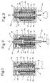
- the numeral 1 denotes a casing of an automatic threading machine.
- the casing 1 houses at least one unit of the automatic machine.
- Numeral 2 denotes an electric motor.
- the electric motor 2 is housed in the casing 1.
- the electric motor 2 is, for example, of the brushless type.
- the electric motor 2 comprises a rotor 3 designed to selectively rotate in both directions relative to the casing 1.
- the rotor 3 is housed in the casing 1 with interposition of bearings 2a, 2b in such a way as to allow the rotation.
- Numeral 3a denotes magnets of the rotor 3.
- Numeral 4 denotes an axis which in the example illustrated represents both an axis of rotation and an axis of symmetry of the rotor 3.
- the rotor 3 is hollow and inside forms a chamber 5 which extends along the axis 4.
- the chamber 5 has a circular cross-section in a plane perpendicular to the axis 4.
- the chamber 5 is partly closed at one end forming a cavity 6 having dimensions transversal to the axis 4 less than the rest of the chamber.
- Numeral 7 denotes a tool holder spindle on which a tool 8 (screw tap) is mounted threaded externally to perform the "tapping".
- the tool 8 has an opening threaded internally for performing the external threading of a component. More specifically, the opening extends along the axis 4 and it is formed by a lateral surface inside the tool. This internal lateral surface is threaded. In this way, the component to be threaded is at least partly inserted in the opening and the internal lateral surface works on the outside of the component so as to thread it.
- the tool holder spindle 7 is movable with a rotating movement about the axis 4, relative to the casing 1.
- the tool holder spindle 7 is movable with a translating movement along the above-mentioned axis 4, relative to the casing 1. More specifically, the tool holder spindle 7 can translate along the axis 4 relative to the rotor 3, preferably inside and relative to the chamber 5 of the rotor 3.
- Figures 1 to 3 illustrate three different positions of the tool holder spindle 7.
- the chamber 5 is suitable for housing the tool holder spindle at least partly.
- Figure 1 illustrates a configuration in which the tool holder spindle 7 is completely housed inside the chamber 5 of the rotor 3.
- the rotor 3 controls the rotating movement of the tool holder spindle 7 about the axis 4.
- the tool holder spindle 7 is supported by the rotor 3 and moves as one with it in the rotating movement about the axis 4.
- the tool holder spindle 7 is connected to the rotor 3 by a shape coupling able to prevent relative rotation about the axis 4 and allow the relative translation along the axis.
- the cavity 6 of the rotor 3 is a cavity for coupling with at least one portion 9 of the tool holder spindle 7. More specifically, the cavity 6 and the portion 9 of the tool holder spindle 7 have respective joined profiles which are suitable for drawing in rotation the tool holder spindle 7 about the axis 4 and for allowing the translation along the axis relative to the rotor 3.
- the cavity 6 of the rotor 3 and the portion 9 of the tool holder spindle 7 have, for example, a hexagonal profile in a plane perpendicular to the axis 4. Different profiles can be used to make the above-mentioned shape coupling.
- Numeral 10 denotes stator windings of the electric motor 2.
- the stator windings 10 arranged radially outside the rotor 3 and the chamber 5.
- the stator windings 10, the rotor 3 and the chamber 5 extend along the axis 4 for at least one shared stretch. More specifically, the stator windings 10, the rotor 3 and the chamber 5 are located inside the casing 1.
- a piston 11 is designed to slide in a sealed fashion inside the chamber 5 and to act on the tool holder spindle 7.
- the tool holder spindle 7 comprises the piston 11.
- the piston 11 has a relative external profile (facing the hollow rotor 3) shaped to match the internal profile of the hollow rotor 3 in such a way as to allow translation of the tool holder spindle 7 relative to the hollow rotor 3.
- the chamber 5 comprises means 12 for connection to a source of pressurised fluid 13 (not illustrated) designed to operate on the piston 11 and, consequently, on the tool holder spindle 7, for generating its translating motion along the axis 4 in at least one direction, preferably a direction 14 approaching a component to be threaded (not illustrated).
- the source of pressurised fluid is a source of compressed air.
- the piston 11 divides the chamber 5 into an upper chamber 5a (with reference to the arrangement of Figure 2 ) and a lower chamber 5b.
- the upper chamber 5a is equipped with connecting means 12.
- the lower chamber 5b comprises return means 15, preferably elastic, operating on the tool holder spindle 7 for generating the translating motion along the axis 4 in a direction moving away from the component to be threaded (direction 16).
- the return means comprise a spring positioned inside the chamber 5.
- the spring is wound around the tool holder spindle 7.
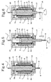
- the machine comprises a male and female screw coupling 17 between the tool holder spindle 7 and the housing casing 1.
- the male and female screw coupling is such as to generate the translating movement of the tool holder spindle 7 drawn in rotation by the rotor 3. Consequently, the male and female screw coupling replaces the source of pressurised fluid and the piston housed in a sealed manner in the chamber 5 illustrated in Figures 1 to 3 .
- the tool holder spindle 7 is threaded on its external surface (male screw) and slides inside a threaded bushing 18 (female screw 17).
- the threaded bushing 18 is integral with the casing 1.
- the portion 9 of the tool holder spindle 7 which couples with the cavity 6 is, for example, formed by a head of the spindle.
- the cavity 6 and the relative portion 9 of the tool holder spindle 7 (head) have respective joined profiles which are suitable for drawing in rotation the tool holder spindle 7 about the axis 4 and for allowing the translation along the axis of the tool holder spindle relative to the rotor 3.
- the chamber 5 has a hexagonal cross-section in a plane perpendicular to the axis 4 and the tool holder spindle 7 comprises the hexagonal-shaped head.
- Different profiles can be made to form the shape coupling between the rotor 3 and the tool holder spindle 7.
- the coupling between the head of the tool holder spindle 7 and the rotor 3 forms a shape coupling able to prevent relative rotation about the axis 4 of the rotor 3 and of the tool holder spindle 7 and allow the relative translation of the tool holder spindle 7 relative to the rotor 3 along the axis 4.
- the movement of the tool 8 is accomplished by direct transmission.
- Figures 1 to 3 correspond to three steps which alternate cyclically.
- the tool holder spindle 7 and, therefore, the tool 8 rotate.
- the source of pressurised fluid air
- the tool 8 is thus introduced, and the source of pressurised fluid is deactivated.
- the tool 8 makes the thread, rotated by the tool holder spindle 7.
- the motor and, therefore, the tool 8 rotate in opposite directions (after a specific electronic command).
- the tool 8 exits the thread and is returned to the initial position by the return spring and its direction of rotation is reversed, ready for a new processing cycle.
- the electric motor 2 is controlled by an electronic control unit which controls one or more of the following parameters: position of the tool holder spindle 7 (from data obtained by resolvers or encoders or Hall sensors etc., generally indicated in the drawings with the numeral 19), direction of rotation of the rotor 3, speed of rotation of the rotor 3, injection of any pressurised fluid for generating the translating motion of the tool holder spindle 7, motor torque.
- the electric motor 2 is controlled by an electronic card. More specifically, the control of the motor torque allows it to be understood when the tool 8 starts the threading operation as the motor torque increases at the moment.
- the electronic control counts the number of revolutions of the tool 8 with the data coming from resolvers or encoders or Hall sensors etc and, after performing the predetermined revolutions, at the end of the threading, the electronic control reverses the direction of rotation of the tool 8, extracting it at the maximum speed of revolution.
- the speed of rotation of the rotor 3 and, therefore, of the tool 8 is not fixed. During the threading, the speed of rotation is such as to not allow the threading parameters to be exceeded which, if exceeded, would adversely affect the service life of the tool 8. During the extraction the speed of rotation of the tool 8 is at its greatest to reduce the processing cycle time.
- the electric motor 2 and, therefore, the tool 8 rotate in opposite directions (after a specific electronic command).
- This rotation returns the tool 8 to the initial position by the male and female screw coupling 17.
- the tool holder spindle 7 stops. Once the tool holder spindle 7 has stopped, the electronic command reverses again the direction of rotation of the electric motor 2 and the tool 8 is ready for a new work cycle.
- the external threading of the tool holder spindle 7 can have a pitch equal to that of the tool 8. In this case, when the tool holder spindle 7 performs a certain number of revolutions, the tool 8 performs the same number of revolutions and the same translation.
- the external threading of the tool holder spindle 7 can have a pitch different to that of the tool 8.
- a compensating spring (not illustrated) is interposed between the tool holder spindle 7 and the tool 8.
- Figures 4 to 6 illustrate a position sensor 20 which informs the control card of the presence (or absence) of the tool holder spindle 7.
Landscapes
- Engineering & Computer Science (AREA)
- Mechanical Engineering (AREA)
- Connection Of Motors, Electrical Generators, Mechanical Devices, And The Like (AREA)
- Turning (AREA)
Claims (13)
- Automatische Gewindeschneidmaschine, umfassend:einen elektrischen Motor (2), umfassend einen Rotor (3), ausgestaltet, um sich selektiv in beide Richtungen zu drehen,eine Werkzeughalterspindel (7), die in der Lage ist, sich mit einer Drehbewegung um eine Achse (4) und mit einer Verschiebungsbewegung entlang der Achse (4) zu bewegen,wobei der Rotor (3) die Drehbewegung der Werkzeughalterspindel (7) um die Achse (4) steuert,wobei die Werkzeughalterspindel (7) vom Rotor (3) getragen wird und sich fest verbunden mit diesem in der Drehbewegung um die Achse (4) dreht, wobei sich der Rotor (3) des elektrischen Motors (2) um die Achse (4) dreht;wobei der Rotor (3) intern eine Kammer (5) aufweist, entlang derer die Werkzeughalterspindel (7) entlang der Achse (4) verschoben werden kann, und die geeignet ist, um zumindest teilweise die Werkzeughalterspindel (7) an mindestens einer Position aufzunehmen, die von der Werkzeughalterspindel (7) eingenommen wird;einen Kolben (11), ausgestaltet, um auf abgedichtete Weise in der Kammer (5) zu gleiten, der Mittel (12) zum Verbinden einer Quelle eines mit Druck beaufschlagten Fluids (13) umfasst, die ausgelegt sind, um auf den Kolben (11) und durch Mittel des Kolbens auf die Werkzeughalterspindel (7) zu wirken, um deren Verschiebungsbewegung entlang der Achse (4) in eine zur Komponente, deren Gewinde zu schneiden ist, hinführende Richtung (14) zu erzeugen;dadurch gekennzeichnet, dass der Kolben (11) die Kammer (5) in eine obere Kammer (5a) und eine untere Kammer (5b) teilt, wobei die obere Kammer (5a) mit Verbindungsmitteln (12) ausgestattet ist und die untere Kammer (5b) Rückführungsmittel (15) aufweist, die auf die Werkzeughalterspindel (7) wirken, um die Verschiebungsbewegung entlang der Achse (4) in eine von der Komponente, deren Gewinde zu schneiden ist,wegführende Richtung zu erzeugen; wobei die Rückführungsmittel (15) eine Feder aufweisen.
- Automatische Gewindeschneidmaschine nach Anspruch 1, wobei die Werkzeughalterspindel (7) mit dem Rotor (3) durch eine Formkupplung verbunden ist, in der Lage, die relative Drehung um die Achse (4) zu vermeiden und deren relative Verschiebung entlang der Achse (4) zu erlauben.
- Automatische Gewindeschneidmaschine nach Anspruch 2, wobei der Rotor (3) einen Hohlraum (6) für die Kupplung mit mindestens einem Abschnitt (9) der Werkzeughalterspindel (7) umfasst und wobei der Hohlraum (6) und der Abschnitt (9) der Werkzeughalterspindel (7) jeweilige verbundene Profile aufweisen, die geeignet sind, um die Werkzeughalterspindel (7) in Drehung um die Achse (4) zu versetzen und um der Werkzeughalterspindel (7) zu erlauben, sich entlang der Achse (4) relativ zum Rotor (3) zu verschieben.
- Automatische Gewindeschneidmaschine nach Anspruch 3, wobei der Hohlraum (6) des Rotors (3) und der Abschnitt (9) der Werkzeughalterspindel (7) ein sechseckiges Profil in einer lotrecht zur Achse (4) verlaufenden Ebene aufweisen.
- Automatische Gewindeschneidmaschine nach Anspruch 3 oder 4, wobei der Hohlraum (6) durch mindestens eine Strecke der Kammer (5) ausgebildet ist, die sich entlang der Achse (4) erstreckt.
- Automatische Gewindeschneidmaschine nach Anspruch 5, wobei der Hohlraum (6) Dimensionen aufweist, die quer zur Achse (4) ausgerichtet und kleiner als der Rest der Kammer (5) sind.
- Automatische Gewindeschneidmaschine nach einem der vorhergehenden Ansprüche, wobei der Rotor (3) hohl ist und innenseitig die Kammer (5) bildet, die sich entlang der Achse (4) erstreckt, entlang derer sich die Werkzeughalterspindel (7) verschieben kann.
- Automatische Gewindeschneidmaschine nach einem der vorhergehenden Ansprüche, wobei der elektrische Motor (2) Statorwicklungen (10) umfasst, die radial außerhalb des Rotors (3) und der Kammer (5) angeordnet sind, und wobei sich die Statorwicklungen (10), der Rotor (3) und die Kammer (5) entlang der Achse (4) auf mindestens einer gemeinsam genutzten Strecke erstrecken.
- Automatische Gewindeschneidmaschine nach einem der vorhergehenden Ansprüche, wobei die Rückführungsmittel eine Feder umfassen, die in der Kammer (5) positioniert und rund um die Werkzeughalterspindel (7) gewunden ist.
- Automatische Gewindeschneidmaschine nach einem der Ansprüche 1 bis 8, wobei der Kolben (11) und die Kammer (5) zusammen einen doppelt wirkenden Zylinder bilden, um die Verschiebungsbewegung entlang der Achse (4) abwechselnd in eine zur Komponente, deren Gewinde zu schneiden ist, hinführenden Richtung (14) und eine von dieser wegführende Richtung (16) zu erzeugen, wobei die Verbindungsmittel (12) eine zusätzliche Leitung umfassen, die eine Verbindung zwischen der Quelle des mit Druck beaufschlagten Fluids (13) und der unteren Kammer (5b) herstellt, um Letzterer das mit Druck beaufschlagte Fluid (13) zuzuführen.
- Automatische Gewindeschneidmaschine nach einem oder mehreren der vorhergehenden Ansprüche, wobei der elektrische Motor (2) über eine elektronische Steuereinheit gesteuert wird, die einen oder mehrere der folgenden Parameter steuert: Position der Werkzeughalterspindel (7), Drehrichtung des Rotors (3), Drehzahl des Rotors (3), Einspritzung eines beliebigen, mit Druck beaufschlagten Fluids (13), um die Verschiebungsbewegung der Werkzeughalterspindel (7) zu erzeugen, Drehmoment des Motors (2).
- Automatische Gewindeschneidmaschine nach einem oder mehreren der vorhergehenden Ansprüche, dadurch gekennzeichnet, dass sie ein Werkzeug (8) mit einem Außengewinde umfasst, das an der Werkzeughalterspindel (7) montiert ist, um ein Gewinde in einem Loch zu schneiden.
- Automatische Gewindeschneidmaschine nach einem der Ansprüche 1 bis 11, dadurch gekennzeichnet, dass sie ein Werkzeug (8) umfasst, das an der Werkzeughalterspindel (7) montiert ist und eine Öffnung mit einem Innengewinde umfasst, um ein Gewinde an der Außenseite einer Komponente zu schneiden.
Applications Claiming Priority (1)
| Application Number | Priority Date | Filing Date | Title |
|---|---|---|---|
| IT000069A ITVR20120069A1 (it) | 2012-04-10 | 2012-04-10 | Macchina automatica per la filettatura |
Publications (3)
| Publication Number | Publication Date |
|---|---|
| EP2650072A1 EP2650072A1 (de) | 2013-10-16 |
| EP2650072B1 EP2650072B1 (de) | 2014-09-03 |
| EP2650072B2 true EP2650072B2 (de) | 2017-06-14 |
Family
ID=46124677
Family Applications (1)
| Application Number | Title | Priority Date | Filing Date |
|---|---|---|---|
| EP13160115.5A Active EP2650072B2 (de) | 2012-04-10 | 2013-03-20 | Automatische Gewindeschneidmaschine |
Country Status (4)
| Country | Link |
|---|---|
| US (1) | US9296055B2 (de) |
| EP (1) | EP2650072B2 (de) |
| JP (1) | JP6133666B2 (de) |
| IT (1) | ITVR20120069A1 (de) |
Families Citing this family (3)
| Publication number | Priority date | Publication date | Assignee | Title |
|---|---|---|---|---|
| CN106141331A (zh) * | 2016-07-27 | 2016-11-23 | 太仓澄天机械有限公司 | 一种机械自动攻丝设备 |
| CN108436200B (zh) * | 2018-05-13 | 2023-09-01 | 陕西理工大学 | 大导程螺母的双电机伺服直驱螺旋挤压装置 |
| DE102018214583A1 (de) * | 2018-08-29 | 2020-03-05 | Sms Group Gmbh | Vorrichtung zum Anstellen eines Gegenstandes |
Family Cites Families (34)
| Publication number | Priority date | Publication date | Assignee | Title |
|---|---|---|---|---|
| US2563497A (en) * | 1951-08-07 | Motor control for rotary tool | ||
| US3124979A (en) * | 1964-03-17 | Tool support and drive | ||
| DE588987C (de) * | 1932-06-09 | 1933-11-30 | Richard Herrmann | Gewindeschneidmaschine mit elektromagnetischer Umkehrsteuerung |
| DE851711C (de) * | 1950-10-25 | 1952-10-06 | Walter Bovensmann | Gewindeschneidmaschine |
| CH277397A (de) * | 1951-05-07 | 1951-08-31 | Inventio Ag | Gewindeschneidmaschine. |
| US2863160A (en) * | 1955-04-14 | 1958-12-09 | Herbert C Ovshinsky | Threading tool spindle feed means reciprocable at a rate in excess of the lead of the threading tool |
| GB812872A (en) * | 1956-06-16 | 1959-05-06 | Stahlkontor Weser Gmbh Maschf | Thread-milling equipment |
| US3158883A (en) * | 1960-08-08 | 1964-12-01 | Laughter Corp | Tapping unit with means to advance spindle to work |
| DE1876823U (de) * | 1963-05-31 | 1963-08-01 | Scheer & Cie C F | Tiefeneinstellvorrichtung an stationaerem bohrmotor mit hohlwelle und verschiebbarer bohrspindel. |
| DE1528088B1 (de) * | 1965-03-13 | 1969-09-18 | Scheer & Cie C F | Bohrvorrichtung,insbesondere zur Holzbearbeitung |
| US3706506A (en) * | 1970-12-21 | 1972-12-19 | Kaufman Mfg Co | Metal cutting machines |
| US3838934A (en) * | 1973-03-02 | 1974-10-01 | R Petroff | Machine tool |
| JPS5620170Y2 (de) * | 1975-12-11 | 1981-05-13 | ||
| US4419032A (en) * | 1981-02-04 | 1983-12-06 | Thomas Flowers | Boring tool |
| US4934040A (en) * | 1986-07-10 | 1990-06-19 | Turchan Manuel C | Spindle driver for machine tools |
| KR950007694B1 (ko) * | 1988-03-28 | 1995-07-14 | 부라더 고교 가부시기가이샤 | 단축복합운동장치 |
| JPH02116406A (ja) * | 1988-10-24 | 1990-05-01 | Brother Ind Ltd | 工具ユニット |
| US5012144A (en) * | 1989-06-27 | 1991-04-30 | Pneumo Abex Corporation | Linear direct drive motor |
| JPH0398716A (ja) * | 1989-09-09 | 1991-04-24 | Brother Ind Ltd | 工作機械 |
| DE3930306A1 (de) * | 1989-09-11 | 1991-03-21 | Microtap Gmbh | Antriebsvorrichtung fuer eine werkzeugmaschine |
| DE4016480C2 (de) * | 1990-05-22 | 1994-07-14 | Gustav Weeke Maschinenbau Gmbh | Spindeleinheit für eine Bohr-Fräsmaschine |
| US5051631A (en) * | 1990-07-16 | 1991-09-24 | Spx Corporation | Electromagnetic solenoid valve with variable force motor |
| JP2593073Y2 (ja) * | 1991-06-25 | 1999-03-31 | 東芝機械株式会社 | 主軸頭に内蔵されたモータの冷却装置 |
| JPH0516064U (ja) * | 1991-08-23 | 1993-03-02 | 浦野 友春 | ネジ切刃具 |
| IT1310503B1 (it) * | 1999-09-30 | 2002-02-18 | Hsd Srl | Testa di foratura portamandrini per macchine utensili atte a lavorareper asportazione di truciolo dei pannelli. |
| DE10014270C1 (de) * | 2000-03-22 | 2001-06-07 | Glimpel Emuge Werk | Gewindeschneidapparat mit Drehrichtungsumkehr |
| WO2002069808A2 (en) * | 2000-11-06 | 2002-09-12 | Suros Surgical Systems, Inc. | Biopsy apparatus |
| ITPN20030002A1 (it) | 2003-01-22 | 2004-07-23 | Bonazzi Federico | Composizione cementizia di materiali isolanti di vario |
| ITPN20030020A1 (it) * | 2003-03-12 | 2004-09-13 | Bordignon Simone | Maschiatore elettromeccanico a comando elettronico. |
| DE10347423A1 (de) * | 2003-10-13 | 2005-05-19 | Otto Bihler Handels-Beteiligungs-Gmbh | Werkzeugtreiberaggregat, insbesondere für den Antrieb eines Gewindefertigungswerkzeugs in einer Gewindefertigungsvorrichtung |
| ITPN20050007A1 (it) | 2005-01-28 | 2005-04-29 | Sandro Morassut | Sistema di monitoraggio e controllo di apparecchiature industriali su mezzi mobili |
| ITPN20050071A1 (it) | 2005-10-12 | 2007-04-13 | Bordignon Alberto | Apparecchio maschiatore automatico perfezionato |
| DE102006032189A1 (de) * | 2006-07-12 | 2008-01-17 | Ima Klessmann Gmbh Holzbearbeitungssysteme | Spindeleinheit für ein mehrspindeliges Bohraggregat |
| JP2009248279A (ja) * | 2008-04-10 | 2009-10-29 | Honda Motor Co Ltd | ねじ加工方法及び同装置 |
-
2012
- 2012-04-10 IT IT000069A patent/ITVR20120069A1/it unknown
-
2013
- 2013-03-20 EP EP13160115.5A patent/EP2650072B2/de active Active
- 2013-04-09 US US13/859,402 patent/US9296055B2/en active Active
- 2013-04-09 JP JP2013081375A patent/JP6133666B2/ja active Active
Also Published As
| Publication number | Publication date |
|---|---|
| US9296055B2 (en) | 2016-03-29 |
| US20130266387A1 (en) | 2013-10-10 |
| JP6133666B2 (ja) | 2017-05-24 |
| EP2650072B1 (de) | 2014-09-03 |
| JP2013215881A (ja) | 2013-10-24 |
| ITVR20120069A1 (it) | 2013-10-11 |
| EP2650072A1 (de) | 2013-10-16 |
Similar Documents
| Publication | Publication Date | Title |
|---|---|---|
| CN105263648B (zh) | 冲压设备 | |
| EP2650072B2 (de) | Automatische Gewindeschneidmaschine | |
| CN104002173A (zh) | 伺服驱动电磁力锁紧换刀机械装置 | |
| CN103994124A (zh) | 一种齿轮齿条缸及具有其的夹紧装置 | |
| CN110666216B (zh) | 一种具有调节打孔深度的安全可靠性高的电动打孔设备 | |
| EP2682231B1 (de) | Hubkolben-servosteuerungsvorrichtung für die hauptwelle einer schleifzugvorrichtung | |
| CN201351645Y (zh) | 摆动液压油缸 | |
| CN201779228U (zh) | 一种新型机械传动机构 | |
| CN203062242U (zh) | 伺服攻钻机 | |
| CN202388000U (zh) | 钻床进刀用液压缸及自动进刀装置 | |
| CN106078302B (zh) | 电动打刀缸和用于电动打刀缸的编码器 | |
| CN103671890A (zh) | 电控变速箱执行器 | |
| US20170304919A1 (en) | Device for Positioning a Thread in a Workpiece | |
| CN103706840B (zh) | 方便在受限空间使用的镗削加工装置 | |
| US20040216290A1 (en) | Electric drive for a shaping die | |
| EP2383107B1 (de) | Elektrohydraulisch betriebener Pressenkopf mit reduziertem Stromverbrauch | |
| ITMO20130148A1 (it) | Apparato di punzonatura | |
| ITMO20130149A1 (it) | Apparato di punzonatura | |
| JPS5811463Y2 (ja) | 電動加工装置 | |
| KR20120010584A (ko) | 전기모터 작동식 실린더 | |
| CN102221074A (zh) | 一种新型机械传动机构 | |
| CN102011848A (zh) | 一种任意旋转与前进的复合运动机构 | |
| CN103831488A (zh) | 一种用于电火花机床的改进的机头移动驱动装置 | |
| CN104384553A (zh) | 镗沉割槽机构 | |
| CN101733434A (zh) | 一种自动钻床 |
Legal Events
| Date | Code | Title | Description |
|---|---|---|---|
| PUAI | Public reference made under article 153(3) epc to a published international application that has entered the european phase |
Free format text: ORIGINAL CODE: 0009012 |
|
| AK | Designated contracting states |
Kind code of ref document: A1 Designated state(s): AL AT BE BG CH CY CZ DE DK EE ES FI FR GB GR HR HU IE IS IT LI LT LU LV MC MK MT NL NO PL PT RO RS SE SI SK SM TR |
|
| AX | Request for extension of the european patent |
Extension state: BA ME |
|
| RAX | Requested extension states of the european patent have changed |
Extension state: ME Payment date: 20140328 Extension state: BA Payment date: 20140328 |
|
| RBV | Designated contracting states (corrected) |
Designated state(s): AL AT BE BG CH CY CZ DE DK EE ES FI FR GB GR HR HU IE IS IT LI LT LU LV MC MK MT NL NO PL PT RO RS SE SI SK SM TR |
|
| GRAP | Despatch of communication of intention to grant a patent |
Free format text: ORIGINAL CODE: EPIDOSNIGR1 |
|
| 17P | Request for examination filed |
Effective date: 20140328 |
|
| INTG | Intention to grant announced |
Effective date: 20140604 |
|
| GRAS | Grant fee paid |
Free format text: ORIGINAL CODE: EPIDOSNIGR3 |
|
| GRAA | (expected) grant |
Free format text: ORIGINAL CODE: 0009210 |
|
| AK | Designated contracting states |
Kind code of ref document: B1 Designated state(s): AL AT BE BG CH CY CZ DE DK EE ES FI FR GB GR HR HU IE IS IT LI LT LU LV MC MK MT NL NO PL PT RO RS SE SI SK SM TR |
|
| AX | Request for extension of the european patent |
Extension state: BA ME |
|
| REG | Reference to a national code |
Ref country code: GB Ref legal event code: FG4D |
|
| REG | Reference to a national code |
Ref country code: AT Ref legal event code: REF Ref document number: 685293 Country of ref document: AT Kind code of ref document: T Effective date: 20140915 Ref country code: CH Ref legal event code: EP |
|
| REG | Reference to a national code |
Ref country code: IE Ref legal event code: FG4D |
|
| REG | Reference to a national code |
Ref country code: DE Ref legal event code: R096 Ref document number: 602013000220 Country of ref document: DE Effective date: 20141016 |
|
| REG | Reference to a national code |
Ref country code: AT Ref legal event code: MK05 Ref document number: 685293 Country of ref document: AT Kind code of ref document: T Effective date: 20140903 |
|
| PG25 | Lapsed in a contracting state [announced via postgrant information from national office to epo] |
Ref country code: GR Free format text: LAPSE BECAUSE OF FAILURE TO SUBMIT A TRANSLATION OF THE DESCRIPTION OR TO PAY THE FEE WITHIN THE PRESCRIBED TIME-LIMIT Effective date: 20141204 Ref country code: SE Free format text: LAPSE BECAUSE OF FAILURE TO SUBMIT A TRANSLATION OF THE DESCRIPTION OR TO PAY THE FEE WITHIN THE PRESCRIBED TIME-LIMIT Effective date: 20140903 Ref country code: ES Free format text: LAPSE BECAUSE OF FAILURE TO SUBMIT A TRANSLATION OF THE DESCRIPTION OR TO PAY THE FEE WITHIN THE PRESCRIBED TIME-LIMIT Effective date: 20140903 Ref country code: NO Free format text: LAPSE BECAUSE OF FAILURE TO SUBMIT A TRANSLATION OF THE DESCRIPTION OR TO PAY THE FEE WITHIN THE PRESCRIBED TIME-LIMIT Effective date: 20141203 Ref country code: LT Free format text: LAPSE BECAUSE OF FAILURE TO SUBMIT A TRANSLATION OF THE DESCRIPTION OR TO PAY THE FEE WITHIN THE PRESCRIBED TIME-LIMIT Effective date: 20140903 Ref country code: FI Free format text: LAPSE BECAUSE OF FAILURE TO SUBMIT A TRANSLATION OF THE DESCRIPTION OR TO PAY THE FEE WITHIN THE PRESCRIBED TIME-LIMIT Effective date: 20140903 |
|
| REG | Reference to a national code |
Ref country code: NL Ref legal event code: VDEP Effective date: 20140903 |
|
| REG | Reference to a national code |
Ref country code: LT Ref legal event code: MG4D |
|
| PG25 | Lapsed in a contracting state [announced via postgrant information from national office to epo] |
Ref country code: CY Free format text: LAPSE BECAUSE OF FAILURE TO SUBMIT A TRANSLATION OF THE DESCRIPTION OR TO PAY THE FEE WITHIN THE PRESCRIBED TIME-LIMIT Effective date: 20140903 Ref country code: HR Free format text: LAPSE BECAUSE OF FAILURE TO SUBMIT A TRANSLATION OF THE DESCRIPTION OR TO PAY THE FEE WITHIN THE PRESCRIBED TIME-LIMIT Effective date: 20140903 Ref country code: RS Free format text: LAPSE BECAUSE OF FAILURE TO SUBMIT A TRANSLATION OF THE DESCRIPTION OR TO PAY THE FEE WITHIN THE PRESCRIBED TIME-LIMIT Effective date: 20140903 Ref country code: AT Free format text: LAPSE BECAUSE OF FAILURE TO SUBMIT A TRANSLATION OF THE DESCRIPTION OR TO PAY THE FEE WITHIN THE PRESCRIBED TIME-LIMIT Effective date: 20140903 Ref country code: LV Free format text: LAPSE BECAUSE OF FAILURE TO SUBMIT A TRANSLATION OF THE DESCRIPTION OR TO PAY THE FEE WITHIN THE PRESCRIBED TIME-LIMIT Effective date: 20140903 |
|
| PG25 | Lapsed in a contracting state [announced via postgrant information from national office to epo] |
Ref country code: NL Free format text: LAPSE BECAUSE OF FAILURE TO SUBMIT A TRANSLATION OF THE DESCRIPTION OR TO PAY THE FEE WITHIN THE PRESCRIBED TIME-LIMIT Effective date: 20140903 |
|
| REG | Reference to a national code |
Ref country code: FR Ref legal event code: PLFP Year of fee payment: 3 |
|
| PG25 | Lapsed in a contracting state [announced via postgrant information from national office to epo] |
Ref country code: RO Free format text: LAPSE BECAUSE OF FAILURE TO SUBMIT A TRANSLATION OF THE DESCRIPTION OR TO PAY THE FEE WITHIN THE PRESCRIBED TIME-LIMIT Effective date: 20140903 Ref country code: PT Free format text: LAPSE BECAUSE OF FAILURE TO SUBMIT A TRANSLATION OF THE DESCRIPTION OR TO PAY THE FEE WITHIN THE PRESCRIBED TIME-LIMIT Effective date: 20150105 Ref country code: EE Free format text: LAPSE BECAUSE OF FAILURE TO SUBMIT A TRANSLATION OF THE DESCRIPTION OR TO PAY THE FEE WITHIN THE PRESCRIBED TIME-LIMIT Effective date: 20140903 Ref country code: CZ Free format text: LAPSE BECAUSE OF FAILURE TO SUBMIT A TRANSLATION OF THE DESCRIPTION OR TO PAY THE FEE WITHIN THE PRESCRIBED TIME-LIMIT Effective date: 20140903 Ref country code: SK Free format text: LAPSE BECAUSE OF FAILURE TO SUBMIT A TRANSLATION OF THE DESCRIPTION OR TO PAY THE FEE WITHIN THE PRESCRIBED TIME-LIMIT Effective date: 20140903 Ref country code: IS Free format text: LAPSE BECAUSE OF FAILURE TO SUBMIT A TRANSLATION OF THE DESCRIPTION OR TO PAY THE FEE WITHIN THE PRESCRIBED TIME-LIMIT Effective date: 20150103 |
|
| REG | Reference to a national code |
Ref country code: DE Ref legal event code: R026 Ref document number: 602013000220 Country of ref document: DE |
|
| PG25 | Lapsed in a contracting state [announced via postgrant information from national office to epo] |
Ref country code: PL Free format text: LAPSE BECAUSE OF FAILURE TO SUBMIT A TRANSLATION OF THE DESCRIPTION OR TO PAY THE FEE WITHIN THE PRESCRIBED TIME-LIMIT Effective date: 20140903 |
|
| PLBI | Opposition filed |
Free format text: ORIGINAL CODE: 0009260 |
|
| 26 | Opposition filed |
Opponent name: OTTO BIHLER MASCHINENFABRIK GMBH & CO. KG Effective date: 20150528 |
|
| PLAX | Notice of opposition and request to file observation + time limit sent |
Free format text: ORIGINAL CODE: EPIDOSNOBS2 |
|
| PG25 | Lapsed in a contracting state [announced via postgrant information from national office to epo] |
Ref country code: DK Free format text: LAPSE BECAUSE OF FAILURE TO SUBMIT A TRANSLATION OF THE DESCRIPTION OR TO PAY THE FEE WITHIN THE PRESCRIBED TIME-LIMIT Effective date: 20140903 |
|
| PG25 | Lapsed in a contracting state [announced via postgrant information from national office to epo] |
Ref country code: LU Free format text: LAPSE BECAUSE OF FAILURE TO SUBMIT A TRANSLATION OF THE DESCRIPTION OR TO PAY THE FEE WITHIN THE PRESCRIBED TIME-LIMIT Effective date: 20150320 Ref country code: MC Free format text: LAPSE BECAUSE OF FAILURE TO SUBMIT A TRANSLATION OF THE DESCRIPTION OR TO PAY THE FEE WITHIN THE PRESCRIBED TIME-LIMIT Effective date: 20140903 |
|
| PLAF | Information modified related to communication of a notice of opposition and request to file observations + time limit |
Free format text: ORIGINAL CODE: EPIDOSCOBS2 |
|
| PG25 | Lapsed in a contracting state [announced via postgrant information from national office to epo] |
Ref country code: SI Free format text: LAPSE BECAUSE OF FAILURE TO SUBMIT A TRANSLATION OF THE DESCRIPTION OR TO PAY THE FEE WITHIN THE PRESCRIBED TIME-LIMIT Effective date: 20140903 |
|
| REG | Reference to a national code |
Ref country code: IE Ref legal event code: MM4A |
|
| PG25 | Lapsed in a contracting state [announced via postgrant information from national office to epo] |
Ref country code: IE Free format text: LAPSE BECAUSE OF NON-PAYMENT OF DUE FEES Effective date: 20150320 |
|
| PLBP | Opposition withdrawn |
Free format text: ORIGINAL CODE: 0009264 |
|
| REG | Reference to a national code |
Ref country code: FR Ref legal event code: PLFP Year of fee payment: 4 |
|
| PLAS | Information related to reply of patent proprietor to notice(s) of opposition deleted |
Free format text: ORIGINAL CODE: EPIDOSDOBS3 |
|
| PLBB | Reply of patent proprietor to notice(s) of opposition received |
Free format text: ORIGINAL CODE: EPIDOSNOBS3 |
|
| PLBB | Reply of patent proprietor to notice(s) of opposition received |
Free format text: ORIGINAL CODE: EPIDOSNOBS3 |
|
| PG25 | Lapsed in a contracting state [announced via postgrant information from national office to epo] |
Ref country code: BE Free format text: LAPSE BECAUSE OF FAILURE TO SUBMIT A TRANSLATION OF THE DESCRIPTION OR TO PAY THE FEE WITHIN THE PRESCRIBED TIME-LIMIT Effective date: 20140903 |
|
| REG | Reference to a national code |
Ref country code: CH Ref legal event code: PL |
|
| PG25 | Lapsed in a contracting state [announced via postgrant information from national office to epo] |
Ref country code: MT Free format text: LAPSE BECAUSE OF FAILURE TO SUBMIT A TRANSLATION OF THE DESCRIPTION OR TO PAY THE FEE WITHIN THE PRESCRIBED TIME-LIMIT Effective date: 20140903 |
|
| PG25 | Lapsed in a contracting state [announced via postgrant information from national office to epo] |
Ref country code: CH Free format text: LAPSE BECAUSE OF NON-PAYMENT OF DUE FEES Effective date: 20160331 Ref country code: LI Free format text: LAPSE BECAUSE OF NON-PAYMENT OF DUE FEES Effective date: 20160331 |
|
| REG | Reference to a national code |
Ref country code: FR Ref legal event code: PLFP Year of fee payment: 5 |
|
| PUAH | Patent maintained in amended form |
Free format text: ORIGINAL CODE: 0009272 |
|
| STAA | Information on the status of an ep patent application or granted ep patent |
Free format text: STATUS: PATENT MAINTAINED AS AMENDED |
|
| PG25 | Lapsed in a contracting state [announced via postgrant information from national office to epo] |
Ref country code: HU Free format text: LAPSE BECAUSE OF FAILURE TO SUBMIT A TRANSLATION OF THE DESCRIPTION OR TO PAY THE FEE WITHIN THE PRESCRIBED TIME-LIMIT; INVALID AB INITIO Effective date: 20130320 Ref country code: BG Free format text: LAPSE BECAUSE OF FAILURE TO SUBMIT A TRANSLATION OF THE DESCRIPTION OR TO PAY THE FEE WITHIN THE PRESCRIBED TIME-LIMIT Effective date: 20140903 |
|
| 27A | Patent maintained in amended form |
Effective date: 20170614 |
|
| AK | Designated contracting states |
Kind code of ref document: B2 Designated state(s): AL AT BE BG CH CY CZ DE DK EE ES FI FR GB GR HR HU IE IS IT LI LT LU LV MC MK MT NL NO PL PT RO RS SE SI SK SM TR |
|
| AX | Request for extension of the european patent |
Extension state: BA ME |
|
| REG | Reference to a national code |
Ref country code: DE Ref legal event code: R102 Ref document number: 602013000220 Country of ref document: DE |
|
| PG25 | Lapsed in a contracting state [announced via postgrant information from national office to epo] |
Ref country code: TR Free format text: LAPSE BECAUSE OF FAILURE TO SUBMIT A TRANSLATION OF THE DESCRIPTION OR TO PAY THE FEE WITHIN THE PRESCRIBED TIME-LIMIT Effective date: 20140903 |
|
| GBPC | Gb: european patent ceased through non-payment of renewal fee |
Effective date: 20170320 |
|
| PG25 | Lapsed in a contracting state [announced via postgrant information from national office to epo] |
Ref country code: GB Free format text: LAPSE BECAUSE OF NON-PAYMENT OF DUE FEES Effective date: 20170320 |
|
| REG | Reference to a national code |
Ref country code: FR Ref legal event code: PLFP Year of fee payment: 6 |
|
| PG25 | Lapsed in a contracting state [announced via postgrant information from national office to epo] |
Ref country code: SM Free format text: LAPSE BECAUSE OF FAILURE TO SUBMIT A TRANSLATION OF THE DESCRIPTION OR TO PAY THE FEE WITHIN THE PRESCRIBED TIME-LIMIT Effective date: 20140903 |
|
| PG25 | Lapsed in a contracting state [announced via postgrant information from national office to epo] |
Ref country code: MK Free format text: LAPSE BECAUSE OF FAILURE TO SUBMIT A TRANSLATION OF THE DESCRIPTION OR TO PAY THE FEE WITHIN THE PRESCRIBED TIME-LIMIT Effective date: 20140903 |
|
| PG25 | Lapsed in a contracting state [announced via postgrant information from national office to epo] |
Ref country code: AL Free format text: LAPSE BECAUSE OF FAILURE TO SUBMIT A TRANSLATION OF THE DESCRIPTION OR TO PAY THE FEE WITHIN THE PRESCRIBED TIME-LIMIT Effective date: 20140903 |
|
| REG | Reference to a national code |
Ref country code: DE Ref legal event code: R081 Ref document number: 602013000220 Country of ref document: DE Owner name: BORDIGNON S.R.L., IT Free format text: FORMER OWNER: BORDIGNON SIMONE S.R.L., ROSSANO VENETO, IT |
|
| PGFP | Annual fee paid to national office [announced via postgrant information from national office to epo] |
Ref country code: FR Payment date: 20230323 Year of fee payment: 11 |
|
| PGFP | Annual fee paid to national office [announced via postgrant information from national office to epo] |
Ref country code: IT Payment date: 20230321 Year of fee payment: 11 Ref country code: DE Payment date: 20230328 Year of fee payment: 11 |
|
| P01 | Opt-out of the competence of the unified patent court (upc) registered |
Effective date: 20230526 |