EP2650042B2 - Pollutant abatement system for gasoline vehicles - Google Patents
Pollutant abatement system for gasoline vehicles Download PDFInfo
- Publication number
- EP2650042B2 EP2650042B2 EP12164142.7A EP12164142A EP2650042B2 EP 2650042 B2 EP2650042 B2 EP 2650042B2 EP 12164142 A EP12164142 A EP 12164142A EP 2650042 B2 EP2650042 B2 EP 2650042B2
- Authority
- EP
- European Patent Office
- Prior art keywords
- twc
- gpf
- treatment system
- gasoline
- downstream
- Prior art date
- Legal status (The legal status is an assumption and is not a legal conclusion. Google has not performed a legal analysis and makes no representation as to the accuracy of the status listed.)
- Active
Links
Images


Classifications
-
- F—MECHANICAL ENGINEERING; LIGHTING; HEATING; WEAPONS; BLASTING
- F01—MACHINES OR ENGINES IN GENERAL; ENGINE PLANTS IN GENERAL; STEAM ENGINES
- F01N—GAS-FLOW SILENCERS OR EXHAUST APPARATUS FOR MACHINES OR ENGINES IN GENERAL; GAS-FLOW SILENCERS OR EXHAUST APPARATUS FOR INTERNAL-COMBUSTION ENGINES
- F01N3/00—Exhaust or silencing apparatus having means for purifying, rendering innocuous, or otherwise treating exhaust
- F01N3/02—Exhaust or silencing apparatus having means for purifying, rendering innocuous, or otherwise treating exhaust for cooling, or for removing solid constituents of, exhaust
- F01N3/021—Exhaust or silencing apparatus having means for purifying, rendering innocuous, or otherwise treating exhaust for cooling, or for removing solid constituents of, exhaust by means of filters
- F01N3/033—Exhaust or silencing apparatus having means for purifying, rendering innocuous, or otherwise treating exhaust for cooling, or for removing solid constituents of, exhaust by means of filters in combination with other devices
- F01N3/035—Exhaust or silencing apparatus having means for purifying, rendering innocuous, or otherwise treating exhaust for cooling, or for removing solid constituents of, exhaust by means of filters in combination with other devices with catalytic reactors
-
- B—PERFORMING OPERATIONS; TRANSPORTING
- B01—PHYSICAL OR CHEMICAL PROCESSES OR APPARATUS IN GENERAL
- B01D—SEPARATION
- B01D53/00—Separation of gases or vapours; Recovering vapours of volatile solvents from gases; Chemical or biological purification of waste gases, e.g. engine exhaust gases, smoke, fumes, flue gases, aerosols
- B01D53/34—Chemical or biological purification of waste gases
- B01D53/92—Chemical or biological purification of waste gases of engine exhaust gases
- B01D53/94—Chemical or biological purification of waste gases of engine exhaust gases by catalytic processes
- B01D53/9445—Simultaneously removing carbon monoxide, hydrocarbons or nitrogen oxides making use of three-way catalysts [TWC] or four-way-catalysts [FWC]
- B01D53/945—Simultaneously removing carbon monoxide, hydrocarbons or nitrogen oxides making use of three-way catalysts [TWC] or four-way-catalysts [FWC] characterised by a specific catalyst
-
- B—PERFORMING OPERATIONS; TRANSPORTING
- B01—PHYSICAL OR CHEMICAL PROCESSES OR APPARATUS IN GENERAL
- B01D—SEPARATION
- B01D53/00—Separation of gases or vapours; Recovering vapours of volatile solvents from gases; Chemical or biological purification of waste gases, e.g. engine exhaust gases, smoke, fumes, flue gases, aerosols
- B01D53/34—Chemical or biological purification of waste gases
- B01D53/92—Chemical or biological purification of waste gases of engine exhaust gases
- B01D53/94—Chemical or biological purification of waste gases of engine exhaust gases by catalytic processes
- B01D53/9445—Simultaneously removing carbon monoxide, hydrocarbons or nitrogen oxides making use of three-way catalysts [TWC] or four-way-catalysts [FWC]
- B01D53/9454—Simultaneously removing carbon monoxide, hydrocarbons or nitrogen oxides making use of three-way catalysts [TWC] or four-way-catalysts [FWC] characterised by a specific device
-
- B—PERFORMING OPERATIONS; TRANSPORTING
- B01—PHYSICAL OR CHEMICAL PROCESSES OR APPARATUS IN GENERAL
- B01J—CHEMICAL OR PHYSICAL PROCESSES, e.g. CATALYSIS OR COLLOID CHEMISTRY; THEIR RELEVANT APPARATUS
- B01J23/00—Catalysts comprising metals or metal oxides or hydroxides, not provided for in group B01J21/00
- B01J23/38—Catalysts comprising metals or metal oxides or hydroxides, not provided for in group B01J21/00 of noble metals
- B01J23/40—Catalysts comprising metals or metal oxides or hydroxides, not provided for in group B01J21/00 of noble metals of the platinum group metals
- B01J23/44—Palladium
-
- B—PERFORMING OPERATIONS; TRANSPORTING
- B01—PHYSICAL OR CHEMICAL PROCESSES OR APPARATUS IN GENERAL
- B01J—CHEMICAL OR PHYSICAL PROCESSES, e.g. CATALYSIS OR COLLOID CHEMISTRY; THEIR RELEVANT APPARATUS
- B01J23/00—Catalysts comprising metals or metal oxides or hydroxides, not provided for in group B01J21/00
- B01J23/38—Catalysts comprising metals or metal oxides or hydroxides, not provided for in group B01J21/00 of noble metals
- B01J23/40—Catalysts comprising metals or metal oxides or hydroxides, not provided for in group B01J21/00 of noble metals of the platinum group metals
- B01J23/46—Ruthenium, rhodium, osmium or iridium
- B01J23/462—Ruthenium
-
- B—PERFORMING OPERATIONS; TRANSPORTING
- B01—PHYSICAL OR CHEMICAL PROCESSES OR APPARATUS IN GENERAL
- B01J—CHEMICAL OR PHYSICAL PROCESSES, e.g. CATALYSIS OR COLLOID CHEMISTRY; THEIR RELEVANT APPARATUS
- B01J35/00—Catalysts, in general, characterised by their form or physical properties
- B01J35/19—Catalysts containing parts with different compositions
-
- B—PERFORMING OPERATIONS; TRANSPORTING
- B01—PHYSICAL OR CHEMICAL PROCESSES OR APPARATUS IN GENERAL
- B01J—CHEMICAL OR PHYSICAL PROCESSES, e.g. CATALYSIS OR COLLOID CHEMISTRY; THEIR RELEVANT APPARATUS
- B01J37/00—Processes, in general, for preparing catalysts; Processes, in general, for activation of catalysts
- B01J37/02—Impregnation, coating or precipitation
- B01J37/03—Precipitation; Co-precipitation
- B01J37/038—Precipitation; Co-precipitation to form slurries or suspensions, e.g. a washcoat
-
- F—MECHANICAL ENGINEERING; LIGHTING; HEATING; WEAPONS; BLASTING
- F01—MACHINES OR ENGINES IN GENERAL; ENGINE PLANTS IN GENERAL; STEAM ENGINES
- F01N—GAS-FLOW SILENCERS OR EXHAUST APPARATUS FOR MACHINES OR ENGINES IN GENERAL; GAS-FLOW SILENCERS OR EXHAUST APPARATUS FOR INTERNAL-COMBUSTION ENGINES
- F01N13/00—Exhaust or silencing apparatus characterised by constructional features
- F01N13/009—Exhaust or silencing apparatus characterised by constructional features having two or more separate purifying devices arranged in series
-
- F—MECHANICAL ENGINEERING; LIGHTING; HEATING; WEAPONS; BLASTING
- F01—MACHINES OR ENGINES IN GENERAL; ENGINE PLANTS IN GENERAL; STEAM ENGINES
- F01N—GAS-FLOW SILENCERS OR EXHAUST APPARATUS FOR MACHINES OR ENGINES IN GENERAL; GAS-FLOW SILENCERS OR EXHAUST APPARATUS FOR INTERNAL-COMBUSTION ENGINES
- F01N3/00—Exhaust or silencing apparatus having means for purifying, rendering innocuous, or otherwise treating exhaust
- F01N3/08—Exhaust or silencing apparatus having means for purifying, rendering innocuous, or otherwise treating exhaust for rendering innocuous
- F01N3/10—Exhaust or silencing apparatus having means for purifying, rendering innocuous, or otherwise treating exhaust for rendering innocuous by thermal or catalytic conversion of noxious components of exhaust
- F01N3/101—Three-way catalysts
-
- F—MECHANICAL ENGINEERING; LIGHTING; HEATING; WEAPONS; BLASTING
- F01—MACHINES OR ENGINES IN GENERAL; ENGINE PLANTS IN GENERAL; STEAM ENGINES
- F01N—GAS-FLOW SILENCERS OR EXHAUST APPARATUS FOR MACHINES OR ENGINES IN GENERAL; GAS-FLOW SILENCERS OR EXHAUST APPARATUS FOR INTERNAL-COMBUSTION ENGINES
- F01N3/00—Exhaust or silencing apparatus having means for purifying, rendering innocuous, or otherwise treating exhaust
- F01N3/08—Exhaust or silencing apparatus having means for purifying, rendering innocuous, or otherwise treating exhaust for rendering innocuous
- F01N3/10—Exhaust or silencing apparatus having means for purifying, rendering innocuous, or otherwise treating exhaust for rendering innocuous by thermal or catalytic conversion of noxious components of exhaust
- F01N3/18—Exhaust or silencing apparatus having means for purifying, rendering innocuous, or otherwise treating exhaust for rendering innocuous by thermal or catalytic conversion of noxious components of exhaust characterised by methods of operation; Control
- F01N3/20—Exhaust or silencing apparatus having means for purifying, rendering innocuous, or otherwise treating exhaust for rendering innocuous by thermal or catalytic conversion of noxious components of exhaust characterised by methods of operation; Control specially adapted for catalytic conversion
- F01N3/206—Adding periodically or continuously substances to exhaust gases for promoting purification, e.g. catalytic material in liquid form, NOx reducing agents
-
- B—PERFORMING OPERATIONS; TRANSPORTING
- B01—PHYSICAL OR CHEMICAL PROCESSES OR APPARATUS IN GENERAL
- B01D—SEPARATION
- B01D2255/00—Catalysts
- B01D2255/10—Noble metals or compounds thereof
- B01D2255/102—Platinum group metals
-
- B—PERFORMING OPERATIONS; TRANSPORTING
- B01—PHYSICAL OR CHEMICAL PROCESSES OR APPARATUS IN GENERAL
- B01D—SEPARATION
- B01D2255/00—Catalysts
- B01D2255/10—Noble metals or compounds thereof
- B01D2255/102—Platinum group metals
- B01D2255/1023—Palladium
-
- B—PERFORMING OPERATIONS; TRANSPORTING
- B01—PHYSICAL OR CHEMICAL PROCESSES OR APPARATUS IN GENERAL
- B01D—SEPARATION
- B01D2255/00—Catalysts
- B01D2255/10—Noble metals or compounds thereof
- B01D2255/102—Platinum group metals
- B01D2255/1025—Rhodium
-
- B—PERFORMING OPERATIONS; TRANSPORTING
- B01—PHYSICAL OR CHEMICAL PROCESSES OR APPARATUS IN GENERAL
- B01D—SEPARATION
- B01D2255/00—Catalysts
- B01D2255/90—Physical characteristics of catalysts
- B01D2255/904—Multiple catalysts
-
- B—PERFORMING OPERATIONS; TRANSPORTING
- B01—PHYSICAL OR CHEMICAL PROCESSES OR APPARATUS IN GENERAL
- B01D—SEPARATION
- B01D2255/00—Catalysts
- B01D2255/90—Physical characteristics of catalysts
- B01D2255/915—Catalyst supported on particulate filters
- B01D2255/9155—Wall flow filters
-
- B—PERFORMING OPERATIONS; TRANSPORTING
- B01—PHYSICAL OR CHEMICAL PROCESSES OR APPARATUS IN GENERAL
- B01D—SEPARATION
- B01D2255/00—Catalysts
- B01D2255/90—Physical characteristics of catalysts
- B01D2255/92—Dimensions
- B01D2255/9205—Porosity
-
- B—PERFORMING OPERATIONS; TRANSPORTING
- B01—PHYSICAL OR CHEMICAL PROCESSES OR APPARATUS IN GENERAL
- B01J—CHEMICAL OR PHYSICAL PROCESSES, e.g. CATALYSIS OR COLLOID CHEMISTRY; THEIR RELEVANT APPARATUS
- B01J21/00—Catalysts comprising the elements, oxides, or hydroxides of magnesium, boron, aluminium, carbon, silicon, titanium, zirconium, or hafnium
- B01J21/02—Boron or aluminium; Oxides or hydroxides thereof
- B01J21/04—Alumina
-
- B—PERFORMING OPERATIONS; TRANSPORTING
- B01—PHYSICAL OR CHEMICAL PROCESSES OR APPARATUS IN GENERAL
- B01J—CHEMICAL OR PHYSICAL PROCESSES, e.g. CATALYSIS OR COLLOID CHEMISTRY; THEIR RELEVANT APPARATUS
- B01J23/00—Catalysts comprising metals or metal oxides or hydroxides, not provided for in group B01J21/00
- B01J23/38—Catalysts comprising metals or metal oxides or hydroxides, not provided for in group B01J21/00 of noble metals
- B01J23/40—Catalysts comprising metals or metal oxides or hydroxides, not provided for in group B01J21/00 of noble metals of the platinum group metals
-
- B—PERFORMING OPERATIONS; TRANSPORTING
- B01—PHYSICAL OR CHEMICAL PROCESSES OR APPARATUS IN GENERAL
- B01J—CHEMICAL OR PHYSICAL PROCESSES, e.g. CATALYSIS OR COLLOID CHEMISTRY; THEIR RELEVANT APPARATUS
- B01J35/00—Catalysts, in general, characterised by their form or physical properties
- B01J35/50—Catalysts, in general, characterised by their form or physical properties characterised by their shape or configuration
- B01J35/56—Foraminous structures having flow-through passages or channels, e.g. grids or three-dimensional [3D] monoliths
-
- F—MECHANICAL ENGINEERING; LIGHTING; HEATING; WEAPONS; BLASTING
- F01—MACHINES OR ENGINES IN GENERAL; ENGINE PLANTS IN GENERAL; STEAM ENGINES
- F01N—GAS-FLOW SILENCERS OR EXHAUST APPARATUS FOR MACHINES OR ENGINES IN GENERAL; GAS-FLOW SILENCERS OR EXHAUST APPARATUS FOR INTERNAL-COMBUSTION ENGINES
- F01N2250/00—Combinations of different methods of purification
- F01N2250/02—Combinations of different methods of purification filtering and catalytic conversion
-
- F—MECHANICAL ENGINEERING; LIGHTING; HEATING; WEAPONS; BLASTING
- F01—MACHINES OR ENGINES IN GENERAL; ENGINE PLANTS IN GENERAL; STEAM ENGINES
- F01N—GAS-FLOW SILENCERS OR EXHAUST APPARATUS FOR MACHINES OR ENGINES IN GENERAL; GAS-FLOW SILENCERS OR EXHAUST APPARATUS FOR INTERNAL-COMBUSTION ENGINES
- F01N2340/00—Dimensional characteristics of the exhaust system, e.g. length, diameter or volume of the exhaust apparatus; Spatial arrangements of exhaust apparatuses
- F01N2340/02—Distance of the exhaust apparatus to the engine or between two exhaust apparatuses
-
- F—MECHANICAL ENGINEERING; LIGHTING; HEATING; WEAPONS; BLASTING
- F01—MACHINES OR ENGINES IN GENERAL; ENGINE PLANTS IN GENERAL; STEAM ENGINES
- F01N—GAS-FLOW SILENCERS OR EXHAUST APPARATUS FOR MACHINES OR ENGINES IN GENERAL; GAS-FLOW SILENCERS OR EXHAUST APPARATUS FOR INTERNAL-COMBUSTION ENGINES
- F01N2340/00—Dimensional characteristics of the exhaust system, e.g. length, diameter or volume of the exhaust apparatus; Spatial arrangements of exhaust apparatuses
- F01N2340/06—Arrangement of the exhaust apparatus relative to the turbine of a turbocharger
-
- F—MECHANICAL ENGINEERING; LIGHTING; HEATING; WEAPONS; BLASTING
- F01—MACHINES OR ENGINES IN GENERAL; ENGINE PLANTS IN GENERAL; STEAM ENGINES
- F01N—GAS-FLOW SILENCERS OR EXHAUST APPARATUS FOR MACHINES OR ENGINES IN GENERAL; GAS-FLOW SILENCERS OR EXHAUST APPARATUS FOR INTERNAL-COMBUSTION ENGINES
- F01N2510/00—Surface coverings
- F01N2510/06—Surface coverings for exhaust purification, e.g. catalytic reaction
- F01N2510/068—Surface coverings for exhaust purification, e.g. catalytic reaction characterised by the distribution of the catalytic coatings
-
- F—MECHANICAL ENGINEERING; LIGHTING; HEATING; WEAPONS; BLASTING
- F01—MACHINES OR ENGINES IN GENERAL; ENGINE PLANTS IN GENERAL; STEAM ENGINES
- F01N—GAS-FLOW SILENCERS OR EXHAUST APPARATUS FOR MACHINES OR ENGINES IN GENERAL; GAS-FLOW SILENCERS OR EXHAUST APPARATUS FOR INTERNAL-COMBUSTION ENGINES
- F01N3/00—Exhaust or silencing apparatus having means for purifying, rendering innocuous, or otherwise treating exhaust
- F01N3/08—Exhaust or silencing apparatus having means for purifying, rendering innocuous, or otherwise treating exhaust for rendering innocuous
- F01N3/10—Exhaust or silencing apparatus having means for purifying, rendering innocuous, or otherwise treating exhaust for rendering innocuous by thermal or catalytic conversion of noxious components of exhaust
-
- Y—GENERAL TAGGING OF NEW TECHNOLOGICAL DEVELOPMENTS; GENERAL TAGGING OF CROSS-SECTIONAL TECHNOLOGIES SPANNING OVER SEVERAL SECTIONS OF THE IPC; TECHNICAL SUBJECTS COVERED BY FORMER USPC CROSS-REFERENCE ART COLLECTIONS [XRACs] AND DIGESTS
- Y02—TECHNOLOGIES OR APPLICATIONS FOR MITIGATION OR ADAPTATION AGAINST CLIMATE CHANGE
- Y02A—TECHNOLOGIES FOR ADAPTATION TO CLIMATE CHANGE
- Y02A50/00—TECHNOLOGIES FOR ADAPTATION TO CLIMATE CHANGE in human health protection, e.g. against extreme weather
- Y02A50/20—Air quality improvement or preservation, e.g. vehicle emission control or emission reduction by using catalytic converters
-
- Y—GENERAL TAGGING OF NEW TECHNOLOGICAL DEVELOPMENTS; GENERAL TAGGING OF CROSS-SECTIONAL TECHNOLOGIES SPANNING OVER SEVERAL SECTIONS OF THE IPC; TECHNICAL SUBJECTS COVERED BY FORMER USPC CROSS-REFERENCE ART COLLECTIONS [XRACs] AND DIGESTS
- Y02—TECHNOLOGIES OR APPLICATIONS FOR MITIGATION OR ADAPTATION AGAINST CLIMATE CHANGE
- Y02T—CLIMATE CHANGE MITIGATION TECHNOLOGIES RELATED TO TRANSPORTATION
- Y02T10/00—Road transport of goods or passengers
- Y02T10/10—Internal combustion engine [ICE] based vehicles
- Y02T10/12—Improving ICE efficiencies
Definitions
- the present invention is directed to a pollutant abatement system for vehicles powered by a gasoline combustion engine, in particular a gasoline direct injection engine (GDI).
- GDI gasoline direct injection engine
- this invention is concerned with a process of efficiently mitigating noxious compounds in the exhaust of such engines by applying the inventive abatement system to fulfill future legislative exhaust regulations.
- Exhaust gases from internal combustion engines operated with a predominantly stoichiometric air/fuel mixture like e.g. port-fuel injection (PFI) engines, are cleaned according to conventional methods with the aid of three-way catalytic converters. These are capable of converting the three essentially gaseous pollutants of the engine, specifically hydrocarbons, carbon monoxide, and nitrogen oxides, simultaneously to harmless components. Apart from the gaseous hydrocarbon (HC), carbon monoxide (CO) and nitrogen oxide (NOx) pollutants, the exhaust gas of gasoline engines also contains little ultrafine particulate matter (PM), which results from the incomplete combustion of the fuel and consists essentially of soot.
- PM ultrafine particulate matter
- GDI gasoline direct injection
- a concern related to GDI vehicles is the mentioned particle emission originating from this engine type, especially due to the relatively small particle sizes and therefore potentially more hazardous nature of these particles.
- Euro 5b emission legislation stage in the beginning of 2011 all new registered Diesel passenger cars have to comply with a particulate mass limit of 4.5 mg/km as well as with a solid particle number limit of 6x10 11 #/km (table 1).
- the introduction of a particle number limit for gasoline vehicles was postponed to the Euro 6 emission legislation stage which will come into effect September 2014. It is anticipated that the limits for spark ignited vehicles will be the same as those for compression ignited vehicles to arrive at technology-neutral emission legislation.
- Gasoline vehicles with port-fuel injection usually comply with the proposed particle emission target of 600 billion particles per kilometer.
- a study by Braisher et al. revealed that particle number emissions by direct injection vehicles were over a magnitude higher than with port-fuel injection vehicles with a large portion of the particles being emitted during the cold start of the driving cycle ( Braisher, M., Stone, R., Price, P., "Particle Number Emissions from a Range of European Vehicles," SAE Technical Paper 2010-01-0786, 2010 , doi: 10.4271/2010-01-0786). Particulate mass emissions exhibited the same trend.
- Catalytic systems have already been proposed which try to efficiently cope with all of the pollutants emitted by GDI engines.
- these systems are designed in a layout in which a close-coupled TWC is followed by a wall-flow filter (catalyzed gasoline particulate filter; GPF).
- GPF catalyzed gasoline particulate filter
- the wall-flow filter carries a catalytic functionality, e.g. a further TWC.
- the US20100293929 deals with exhaust gas emission aftertreatment systems for spark ignition engines.
- Various embodiments of the system mentioned here comprise both a close coupled TWC device, and an underfloor treatment device.
- the underfloor treatment device may either have TWC or NOx reduction functionality.
- the system can embrace a wall-flow TWC coated filter element (8).
- the TWC catalyst formulation on the filter is operable to reduce particulate matter, as well as the gases treated by conventional TWC devices. So the wall-flow filter is able to reduce HC, CO, NOx when its light off temperature is reached, and effectively reduce particulate matter emissions under all operating conditions.
- no more details with regard to the content of the close-coupled TWC and the TWC coated filter are given in this disclosure.
- US20110252773 discloses an exhaust system suitable for use in conjunction with gasoline engines to capture particulates in addition to reducing gaseous emissions such as hydrocarbons, nitrogen oxides, and carbon monoxide.
- the TWC coated particulate filter has washcoat loadings in the range of at least 1 to 4 g/in 3 to minimize backpressure penalties.
- the porosity of the coated filter may be in the range of 55 to 70% and may comprise certain mean pore size distributions.
- the catalyzed filter may need to be used in conjunction with a second TWC in order to meet regulations and car manufacturer requirements ( Fig. 1 ). However, the upstream TWC may be smaller than otherwise needed because of the downstream TWC coated particulate filter or may even be omitted if the filter provides full TWC functionality.
- the catalyzed particulate filter may comprise a zoned layout, in which the upstream zone comprises the palladium component in an amount that is greater than the amount of the palladium component in the downstream zone. It is said that the catalyzed filter should contain between 2-100 g/ft 3 palladium in the upstream zone and 1-20 g/ft 3 palladium in the downstream zone.
- the systems tested in this application comprise precious metal loadings in the TWC and the catalyzed filter of ⁇ 30g/ft 3 .
- the palladium to rhodium ratios are in each case 27/3 for both catalytic devices.
- the US20110158871 concerns an exhaust system for a vehicular positive ignition internal combustion engine.
- the system comprises a three-way catalyst washcoat disposed on a substrate monolith located upstream of the filter, which is also coated with a TWC washcoat.
- the upstream device comprises equally or less than 75% of the total mass of the three-way catalyst washcoat in the exhaust system.
- the behaviour of the wall-flow filter was examined in view of the mean pore size of the filter substrate and its washcoat loading.
- the close-coupled TWC comprises a TWC-washcoat like the downstream TWC coated ceramic wall-flow filter.
- the wall-flow filter substrate comprises e.g. a Pd-Rh-ratio of 16:1 at a loading of 85 g/ft 3 .
- the close-coupled TWC was coated with an identical loading.
- the present invention concerns a gasoline engine exhaust treatment system comprising a close-coupled three-way catalyst (TWC), which is disposed on a flow through substrate, and a downstream catalyzed gasoline wall-flow particulate filter (GPF).
- TWC close-coupled three-way catalyst
- GPF downstream catalyzed gasoline wall-flow particulate filter
- This system is characterized by a certain ratio of precious metal content of the close-coupled TWC compared to the downstream catalyzed gasoline particulate filter.
- the amount of platinum group metals in the TWC exceeds the amount of platinum group metals in the GPF by a factor of at least 5, wherein both devices comprise platinum group metals Pd and Rh.
- This system is able to dispense with the objectives mentioned above in a relatively easy but nonetheless surprising fashion.
- Both the upstream TWC and the downstream GPF advantageously comprise mixtures of the precious metals palladium and rhodium with platinum.
- Other precious metals e.g. iridium, rhenium, ruthenium, silver, gold may also be present. However, if present the latter PGMs are contained in less amounts compared to palladium and rhodium, respectively. It is most preferred that the platinum group metals present in the upstream TWC and the downstream GPF are palladium and rhodium only.
- the ratio of platinum group metals in the upstream TWC and the downstream GPF is at least 6, more preferred at least 7, still further preferred at least 8 or 9, and ultimately preferred at least 10. This is in particular preferred if the platinum group metals involved in the system are Pd and Rh only.
- the platinum group metal content of the downstream gasoline particulate filter helps to accelerate the combustion of the soot accumulated in the filter.
- an upper limit of the ratio of TWC vs. GPF in platinum group metals is drawn by the fact that the GPF should still comprise a beneficial TWC functionality which is sufficient to supplement the functionality of the upstream TWC in an economic and ecological manner, and still should show the ability to accelerate burning off soot particles. It is obvious that in this connection also the amount of platinum group metals in the upstream TWC should be balanced by cost factors and the efficiency in mitigating noxious exhaust pollutants via the inventive system.
- this factor may heavily depend on the kind of engine involved and the composition of its exhaust gas, as well as the extent in which the PGMs are effective on the devices in question (e.g. decrease of activity through aging, support used etc.).
- the skilled worker will know how to find the upper limit for the platinum group metal ratio according to the above mentioned parameters. However, this upper limit varies advantageously between 10-23 with preference between 15-20, and most preferably between 16-19.
- the amounts of platinum group metals, e.g. Pd and Rh, on the upstream TWC varies advantageously between 20-200 g/ft 3 , more preferably between 25-120 g/ft 3 , and most preferably around 30-80 g/ft 3 .
- the downstream GPF contrarily shows platinum group metal contents of preferably 2-20 g/ft 3 , more preferably 2-15 g/ft 3 , and most preferably around 2-10 g/ft 3 .
- the platinum group metals in the upstream TWC are present in certain ratio to each other.
- the upstream TWC has a weight ratio of Pd to Rh which varies between 8-40:1, preferably between 10-25:1, and most preferably around 11-19:1.
- the downstream GPF carrying less high a concentration of platinum group metals likewise comprises certain ratios of these platinum group metals.
- the downstream GPF shows a weight ratio of Pd to Rh between 1-10:1, preferably between 1-5:1, and most preferably around 1-3:1.
- the present invention provides for an exhaust treatment system for gasoline direct injection engines.
- the system comprises a TWC device followed by a GPF which is also coated with a catalyst comprising TWC functionality.
- the TWC is - according to the invention - positioned in an upstream part of the exhaust system.
- the TWC device is located in a so-called close-coupled position. This means that the close coupled emission treatment device is positioned near the exhaust output of the exhaust manifold, the engine exhaust output itself or the turbo charger. That is to say that the TWC is preferably located ca. 2-40 cm downstream of the engine, more preferably ca. 5-30 cm and most preferably 5-20 cm away from the respective exhaust output/ turbo charger.
- vehicles have an engine compartment containing the engine and related subsystems and devices, including the close-coupled emission treatment device mentioned above.
- the firewall at the floor of the vehicle separates the engine compartment and driver/passenger compartment from the subfloor subsystems and devices.
- the latter is nominating an underfloor or underbody position of a device if the device is positioned under said vehicle's floor.
- the downstream GPF is located in such an underfloor position.
- the downstream GPF of the invention is, therefore, in fluid communication with the upstream TWC being associated with the engine, turbo charger or manifold output, so that the exhaust gases produced by the direct injection engine are first conveyed through the TWC device, preferably located in a close-coupled position, and then carried through an exhaust pipe to the downstream GPF, preferably positioned in an underfloor location.
- an optimal distance exists between the TWC and the GPF. This distance depends strongly on several aspects, e.g. the engine involved and the system parameters, like activity of TWC vs. GPF.
- the GPF is located 60-150 cm downstream of said output. Most preferably the distance between said output and the GPF inlet is 60-120 cm.
- All, some, or only one of the platinum group metals which are applied to the upstream TWC and/or the downstream GPF can be equally distributed over the respective device, can be present thereon in a zoned layout, or may be arranged in a layered manner.
- the upstream TWC shows a zoned layout with regard to all, some, or only one of the platinum group metals located on it.
- the palladium content can be distributed over the upstream TWC in a non-uniform manner, while advantageously the rhodium content is equally distributed over the entire device. That is to say that only the upstream TWC has a Pd-zoning. More preferably, the palladium content in an inlet zone of the upstream TWC is higher than the palladium content in an outlet zone of the upstream TWC.
- the weight ratio of this palladium content should lie within the limits of 2-10:1, preferably 3-7:1and most preferably around 4-5:1.
- the inlet zone is located from the entrance of the device to less then the total length of it to the outlet.
- the outlet zone is located from the outlet of the device to less then the total length of it to the inlet. Both zones may overlap each other or may be arranged with or without a gap between them.
- the inlet zone has a relative length compared to the substrate of 1/5 - 1/2, more preferably 1/5 - 1/3 and most preferably 1/5 - 1/4.
- the outlet zone has preferably the same length like the inlet zone. In a most preferred embodiment both zones have a length of 7-8 cm and provide for a difference in Pd-loading of 4-5:1 between the respective zones.
- the pores and the porosity of the catalyzed gasoline particulate filter becomes important in that an advantageous balance has to be found between filtering efficiency and backpressure penalty.
- the TWC functionality being present on the filter may give rise to even more backpressure if applied to the filter with a disadvantageous washcoat. It has been found that the backpressure problem can be overcome by choosing specifically optimized washcoat having three-way functionality on GPFs comprising adapted porosities and mean pore sizes.
- the mean pore size of the walls of the GPFs according to this invention may show a rather large mean pore size of > 14 or even > 20 ⁇ m (SAE2007010921). At least the adopted pore sizes seem to be in conflict with recommendations given in the literature (SAE2011010814). Due to the fact that washcoats having appropriately sized particles more or less intrude into the pores of the GPF-walls they help to catch soot but prevent building up backpressure. In a more preferred aspect the mean pore size of the GPF is between 14-25, more preferably between 15-21. The amount of washcoat present on or in the GPF can be properly determined according to the teaching of US20110252773 with respect to above mentioned topics.
- the washcoat is not covering the walls of the GPF according to the invention but is located in the pores themselves.
- the washcoat particles have to be smaller than the mean pore size of the filter. It is, therefore, advantageous if the particle size of particles in the washcoat is less than the mean pore size of the GPF involved.
- the particle size of the washcoat is therefore between 0.1-20 ⁇ m, more preferably between 0.1-15 ⁇ m and most preferably between 0.1-10 ⁇ m.
- the gasoline wall-flow particulate filter involved has a certain porosity. Not only mean pore sizes of the instant GPF are crucial for balancing the backpressure penalty. Also the amount of pores determines the backpressure of a wall-flow filter.
- the gasoline wail-flow particulate filter according to the present invention has a porous wall structure comprising porosities between 45%-75%, preferably the porous structure has a porosity between 55%-70%, and most preferably between 60%-65%.
- a very preferred aspect of the present invention is directed to a gasoline direct injection engine exhaust treatment system comprising a close-coupled three-way catalyst (TWC), e.g. with Pd-zoning, and a downstream TWC-catalyzed gasoline particulate filter (GPF), wherein the mean pore size of the wall-flow particulate filter is around 18-22 ⁇ m, the size of particles in the washcoat applied to the filter is between 1-7 ⁇ m, and the porosity of the filter lies around 60-70%.
- TWC close-coupled three-way catalyst
- GPF gasoline particulate filter
- the present invention is directed to a process for the abatement of noxious pollutants emitted by gasoline engines, wherein the exhaust gas is contacted with a system according to the invention. It is to be understood by those skilled in the art that all the preferred and advantageously mentioned aspects and embodiments of the inventive system also readily apply mutatis mutandis to the present process.
- the TWC catalyst composites are disposed on a substrate.
- the substrate is honeycomb flow through substrate of those materials typically used for preparing catalysts, and will preferably comprise a ceramic or metal honeycomb structure.
- a suitable substrate is a monolithic substrate of the type having fine, parallel gas flow passages extending there through from an inlet or an outlet face of the substrate, such that passages are open to fluid flow there through (referred to as honeycomb flow through substrates).
- the passages which are essentially straight paths from their fluid inlet to their fluid outlet, are defined by walls on which the catalytic material is coated as a washcoat so that the gases flowing through the passages contact the catalytic material.
- the flow passages of the monolithic substrate are thin-walled channels, which can be of any suitable cross-sectional shape and size such as trapezoidal, rectangular, square, sinusoidal, hexagonal, oval, circular, etc.
- Such structures may contain from about 60 - 900 or more gas inlet openings (i.e., cells) per square inch of cross section.
- the ceramic substrate may be made of any suitable refractory material, e.g., cordierite, cordierite-alumina, silicon nitride, zircon mullite, spodumene, alumina-silica magnesia, zircon silicate, sillimanite, a magnesium silicate, zircon, petalite, alumina, an aluminosilicate and the like.
- the substrates useful for the catalyst composite of the present invention may also be metallic in nature and be composed of one or more metals or metal alloys.
- the metallic substrates may be employed in various shapes such as corrugated sheet or monolithic form.
- Preferred metallic supports include the heat resistant metals and metal alloys such as titanium and stainless steel as well as other alloys in which iron is a substantial or major component.
- Such alloys may contain one or more of nickel, chromium, and/or aluminum, and the total amount of these metals may advantageously comprise at least about 15 wt % of the alloy, e.g., about 10 - 25 wt % of chromium, about 3 - 8 wt % of aluminum and up to about 20 wt % of nickel.
- the alloys may also contain small or trace amounts of one or more other metals such as manganese, copper, vanadium, titanium and the like.
- the surface of the metal substrates may be oxidized at high temperatures, e.g., about 1000°C and higher, to improve the resistance to corrosion of the alloys by forming an oxide layer on the surfaces of the substrates. Such high temperature-induced oxidation may enhance the adherence of the refractory metal oxide support and catalytically promoting metal components to the substrate.
- one or more catalyst compositions may be deposited on an open cell foam substrate. Such substrates are well known in the art, and are typically formed of refractory ceramic or metallic materials.
- a treatment system comprising a wall-flow particulate filter which is specially adapted to the treatment of gasoline engine exhaust gas streams, in particular those originating from direct injection gasoline engines.
- any wall-flow filter substrate may be used in the present invention, provided that it allows the effective filtering of particulate matter contained in gasoline engine exhaust gas streams.
- a so called gasoline particulate filter is used as the filter substrate, wherein, according to the present invention, reference to a particulate trap means a filter so sized and configured to trap particulates generated by the combustion reactions in the gasoline engine, preferably in gasoline engines with direct injection technologies.
- the GPF-substrate is a wall-flow monolith or wall-flow filter, and more preferably a wall-flow filter having a honeycomb structure.
- Useful wall-flow substrates include those having a plurality of fine, substantially parallel gas flow passages extending along the longitudinal axis of the substrate. Preferably, each passage is blocked at one end of the substrate body, with alternate passages blocked at opposite end-faces.
- U.S. Pat. No. 4,329,162 is incorporated herein by reference with respect to the disclosure of suitable wall-flow substrates which may be used according to the present invention.
- the particulate filter substrate may be conceived of any material or combination of materials allowing for the filtering of particulate matter contained in gasoline engine exhaust gas without impeding the function of a gasoline engine in fluid communication with the particulate filter.
- porous materials are preferably used as the substrate material, in particular ceramic-like materials such as cordierite, alpha-alumina, silicon carbide, aluminum titanate, silicon nitride, zirconia, mullite, spodumene, alumina-silica-magnesia and zirconium silicate, as well as porous refractory metals and oxides thereof.
- refractory metal refers to one or more metals selected from the group consisting of Ti, Zr, Hf, V, Nb, Ta, Cr, Mo, W, and Re.
- the particulate filter substrate may also be formed of ceramic fiber composite materials.
- the particulate filter substrate is preferably formed from cordierite, silicon carbide, and/or from aluminum titanate. In general, materials are preferred which are able to withstand the high temperatures to which a particulate filter is exposed to when used in the treatment of gasoline engine exhaust gas.
- the particulate filter comprises preferably a particulate filter substrate, a first layer disposed on or in the one surface of the filter substrate which, and optionally a second layer disposed on or in the one surface of the filter substrate.
- the coating is arranged entirely or at least predominately within the porous walls of the wall flow filter substrate.
- the gasoline wall-flow particulate filter and the upstream TWC are coated with an appropriate washcoat carrying a catalyst comprising three-way functionality.
- the washcoat of both devices may be the same or different ones.
- any TWC washcoat may be employed in the treatment system, provided that effective treatment of gasoline engine exhaust gas may be realized.
- Appropriate TWC washcoats in single layer or multilayer design can be found e.g. in EP1974810B1 PCT/EP2011/070541 , EP1974809B1 , or PCT/EP2011/070539 .
- TWC catalysts are employed which comprise platinum group metals Rh and Pd, more preferably they comprise Pd and Rh only.
- the TWC washcoat comprises a catalyst composed out of a metal oxide support material, said support material preferably being selected from the group consisting of alumina, zirconia, zirconia-alumina, barium oxide-alumina, lanthana-alumina, lanthana-zirconia-alumina, and mixtures thereof.
- the metal oxide support material is gamma-alumina.
- the support material is doped with a rare-earth, alkaline earth or refractory metal oxide in an amount preferably ranging from 0.01 to 30 wt.-%, more preferably from 0.05 to 15 wt.-%, even more preferably from 0.1 to 10 wt.-%.
- the rare-earth, alkaline earth or refractory metal oxide is preferably selected from the group consisting of ceria, lanthana, praseodymia, neodymia, barium oxide, strontium oxide, zirconia and mixtures thereof, wherein the rare-earth, alkaline earth or refractory metal oxide is preferably lanthana, barium oxide and/or zirconia.
- the metal oxide support material is gamma-alumina which is preferably doped with a rare-earth, alkaline earth or refractory metal oxide, more preferably with lanthana, barium oxide and/or zirconia.
- the TWC catalyst according to the present invention preferably comprises an oxygen storage component (OSC), said OSC preferably being selected from the group consisting of ceria, praseodymia and mixtures thereof and mixtures of those materials with other metal oxides, more preferably from the group consisting of ceria-zirconia-, ceria-zirconia-lanthana-, ceria-zirconia-neodymia-, ceria-zirconia-praseodymia, ceria-zirconia-yttria-, ceria-zirconia-lanthana-neodymia-, ceria-zirconia-lanthana-praseodymia- or ceria-zirconia-lanthana-yttria-mixtures.
- OSC oxygen storage component
- the catalyst composite can be readily washcoated on a carrier.
- a carrier for a first layer of a specific washcoat, finely divided particles of a high surface area metal oxide such as gamma alumina are slurried in an appropriate vehicle, e.g., water.
- an appropriate vehicle e.g., water.
- platinum group metals e.g., palladium, rhodium, platinum, and/or combinations of the same
- stabilizers and/or promoters such components may be incorporated in the slurry as a mixture of water soluble or water-dispersible compounds or complexes.
- the component in question is utilized in the form of a compound or complex to achieve dispersion of the component on the metal oxide support, e.g. activated alumina, like gamma alumina.
- the term "component” means any compound, complex, or the like which, upon calcination or use thereof, decomposes or otherwise converts to a catalytically active form, usually the metal or the metal oxide. This applies accordingly to all platinum group elements used alone or in combination with one another according to the present invention.
- Water-soluble compounds or water-dispersible compounds or complexes of the metal component may be used as long as the liquid medium used to impregnate or deposit the metal component onto the refractory metal oxide support particles does not adversely react with the metal or its compound or its complex or other components which may be present in the catalyst composition and is capable of being removed from the metal component by volatilization or decomposition upon heating and/or application of a vacuum. In some cases, the completion of removal of the liquid may not take place until the catalyst is placed into use and subjected to the high temperatures encountered during operation. Generally, both from the point of view of economics and environmental aspects, aqueous solutions of soluble compounds or complexes of the precious metals are utilized.
- suitable compounds are palladium nitrate or rhodium nitrate.
- any conceivable method may be employed for the production of the treatment system according to the present invention (for GPF: US2009129995 , EP1789191 , WO2006021336 ).
- the catalyst slurry may permeate the walls of the substrate.
- permeate when used to describe the dispersion of the catalyst slurry on the substrate, means that the catalyst composition is dispersed throughout the wall of the substrate.
- the coated substrates are dried typically at about 100°C, and calcined at a higher temperature (e.g., 300 to 450° C. and up to 550° C.). After calcining, the catalyst loading can be determined through calculation of the coated and uncoated weights of the substrate. As will be apparent to those of skill in the art, the catalyst loading can be modified by altering the solids content of the coating slurry. Alternatively, repeated immersions of the substrate in the coating slurry can be conducted, followed by removal of the excess slurry as described above.
- the catalyst composites of the present invention may be formed in a single layer or multiple layers or zones. In some instances, it may be suitable to prepare one slurry of catalytic material and use this slurry to form multiple layers on the carrier.
- the composites can be readily prepared by processes well known in the prior art. A representative process is set forth below.
- the term "washcoat” has its usual meaning in the art of a thin, adherent coating of a catalytic or other material applied to a substrate carrier material, such as a honeycomb-type carrier member, which is sufficiently porous to permit the passage there through of the gas stream being treated.
- catalysts or functionalities can be associated with the present system, like e.g. SCR functionality and/or OSC functionality and/or NSC functionality etc. ( US20110158871 ; US20090193796 ).
- Emission analyzers were used to measure the gaseous emission CO, CO 2 , NOx, THC and O 2 .
- Exhaust gas sensors are located 2" before (2) and after (4) the TWC and after the GPF (6).
- Thermocouples and pressure sensor were located in similar positions for temperature and back pressure measurement.
- Additional lambda sensors were used to measure air-fuel ratio.
- a Horiba MEXA1000 was used to measure particulate number according to PMP. As particulate number PN was measured undiluted after the GPF the additional dilution step from MEXA1000 was used. The instrument was able to provide time-resolved particle number data.
- the Reference system used a 101.6mm diameter substrate by 152mm in length (3).
- the cell density is 600 cpsi.
- Comparative Examples 1 and Example 2 used the same Reference TWC catalyst technology but with a slightly different PGM loading ((3) and (9)) with an uncatalyzed (5) and catalyzed (8) GPF device, respectively, in the underfloor location.
- Example 3 used a PGM zoned TWC catalyst (9) with a catalyzed GPF (8). All GPF substrates are made of cordierite material with a 65% porosity and a large mean pore size of about 20 ⁇ m.
- Substrate dimensions are 118.4mm in diameter by 152mm in length.
- Cell density and wall thickness are 300 cpsi with 12mil wall thickness.
- the filter substrates were coated with washcoat slurry having a three-way functional composition specifically optimized for usage in GPFs.
- the precious metal loadings of both close-coupled TWC and underbody GPF can be found in Table 2. All systems with catalyzed GPF that were evaluated in this study have lower precious metal costs than the Reference system. All systems were aged in parallel after a fuel-cut aging procedure with a bed temperature of 1030 °C inside the close coupled TWC catalyst. Table 2 - Precious metal loadings and costs of systems shown in Figure 1.
- a 1.4L GDI vehicle was chosen: It was a 2005 MY 1.4 L direct injection engine with turbo charger. The engine is calibrated for Euro 4 emissions and used a production 1.251 close-coupled catalyst. This engine was installed on a high dynamic engine bench equipped with a CVS system for bag analysis, three online analyzer lines (raw gas, after TWC and after GPF) for gaseous emission components and a particulate counter (Horiba MEXA 1000) that was used in undiluted exhaust after the GPF. To measure according to PMP it uses also the additional dilution step. All results shown from the high dynamic engine bench are average values of at least five tests.
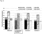
- the particle number emissions measured in the European Driving Cycle of the four exhaust systems described in Figure 1 are shown in Figure 2 .
- the particulate number emissions profile of the TWC only reference system is identical to the raw emissions of the vehicle. There is no measurable particle number abatement from the three-way catalyst on a flow-through substrate. Comparative Examples 1, Example 2 to 3 equipped with Gasoline Particulate Filters reduce the amount of emitted particles drastically.
- Figure 2 summarizes the particle emissions and the filtration efficiency.
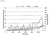
- the particulate emission profile over the NEDC for all systems is shown in Figure 3 .
- the filtration efficiency of each aftertreatment system was calculated proportional to the measurements at the engine-out. Each value represents the average from five NEDC tests.
- Comparative Example 1 With the chosen cordierite type filter the filtration efficiency of Comparative Example 1 is 88% resulting in emission of 1.7 x 10 11 #/km. By applying a washcoat to the filter the filtration efficiency increased to 99% and 99% for Example 2 and Example 3 resulting in 1.4 x 10 10 #/km and 1.2 x 10 10 #/km respectively. Both systems safely meet the proposed limits.
Landscapes
- Chemical & Material Sciences (AREA)
- Engineering & Computer Science (AREA)
- Chemical Kinetics & Catalysis (AREA)
- Combustion & Propulsion (AREA)
- Materials Engineering (AREA)
- Organic Chemistry (AREA)
- Health & Medical Sciences (AREA)
- Mechanical Engineering (AREA)
- General Engineering & Computer Science (AREA)
- Oil, Petroleum & Natural Gas (AREA)
- Biomedical Technology (AREA)
- Environmental & Geological Engineering (AREA)
- Analytical Chemistry (AREA)
- General Chemical & Material Sciences (AREA)
- Toxicology (AREA)
- Exhaust Gas After Treatment (AREA)
- Processes For Solid Components From Exhaust (AREA)
- Exhaust Gas Treatment By Means Of Catalyst (AREA)
- Catalysts (AREA)
- Filtering Of Dispersed Particles In Gases (AREA)
Priority Applications (11)
| Application Number | Priority Date | Filing Date | Title |
|---|---|---|---|
| EP12164142.7A EP2650042B2 (en) | 2012-04-13 | 2012-04-13 | Pollutant abatement system for gasoline vehicles |
| EP13714941.5A EP2836288A1 (en) | 2012-04-13 | 2013-04-10 | Pollutant abatement system for gasoline vehicles |
| KR1020147028510A KR102107978B1 (ko) | 2012-04-13 | 2013-04-10 | 가솔린 차량용 오염물 감소 시스템 |
| CN201380019630.7A CN104661730B (zh) | 2012-04-13 | 2013-04-10 | 用于汽油车辆的污染物减少系统 |
| RU2014145429A RU2618685C2 (ru) | 2012-04-13 | 2013-04-10 | Система нейтрализации вредных выбросов для транспортных средств с бензиновыми двигателями |
| JP2015504933A JP2015528868A (ja) | 2012-04-13 | 2013-04-10 | ガソリン車用の汚染物質低減装置 |
| BR112014024554-1A BR112014024554B1 (pt) | 2012-04-13 | 2013-04-10 | sistema de tratamento de exaustão de motor a gasolina |
| US14/389,716 US9581063B2 (en) | 2012-04-13 | 2013-04-10 | Pollutant abatement system for gasoline vehicles |
| PCT/EP2013/057432 WO2013153081A1 (en) | 2012-04-13 | 2013-04-10 | Pollutant abatement system for gasoline vehicles |
| JP2017233220A JP6785749B2 (ja) | 2012-04-13 | 2017-12-05 | ガソリン車用の汚染物質低減装置 |
| JP2019136977A JP2020008022A (ja) | 2012-04-13 | 2019-07-25 | ガソリン車用の汚染物質低減装置 |
Applications Claiming Priority (1)
| Application Number | Priority Date | Filing Date | Title |
|---|---|---|---|
| EP12164142.7A EP2650042B2 (en) | 2012-04-13 | 2012-04-13 | Pollutant abatement system for gasoline vehicles |
Publications (3)
| Publication Number | Publication Date |
|---|---|
| EP2650042A1 EP2650042A1 (en) | 2013-10-16 |
| EP2650042B1 EP2650042B1 (en) | 2014-11-26 |
| EP2650042B2 true EP2650042B2 (en) | 2020-09-02 |
Family
ID=45937116
Family Applications (2)
| Application Number | Title | Priority Date | Filing Date |
|---|---|---|---|
| EP12164142.7A Active EP2650042B2 (en) | 2012-04-13 | 2012-04-13 | Pollutant abatement system for gasoline vehicles |
| EP13714941.5A Withdrawn EP2836288A1 (en) | 2012-04-13 | 2013-04-10 | Pollutant abatement system for gasoline vehicles |
Family Applications After (1)
| Application Number | Title | Priority Date | Filing Date |
|---|---|---|---|
| EP13714941.5A Withdrawn EP2836288A1 (en) | 2012-04-13 | 2013-04-10 | Pollutant abatement system for gasoline vehicles |
Country Status (8)
| Country | Link |
|---|---|
| US (1) | US9581063B2 (enExample) |
| EP (2) | EP2650042B2 (enExample) |
| JP (3) | JP2015528868A (enExample) |
| KR (1) | KR102107978B1 (enExample) |
| CN (1) | CN104661730B (enExample) |
| BR (1) | BR112014024554B1 (enExample) |
| RU (1) | RU2618685C2 (enExample) |
| WO (1) | WO2013153081A1 (enExample) |
Families Citing this family (64)
| Publication number | Priority date | Publication date | Assignee | Title |
|---|---|---|---|---|
| GB201207313D0 (en) | 2012-04-24 | 2012-06-13 | Johnson Matthey Plc | Filter substrate comprising three-way catalyst |
| GB2513364B (en) | 2013-04-24 | 2019-06-19 | Johnson Matthey Plc | Positive ignition engine and exhaust system comprising catalysed zone-coated filter substrate |
| GB201302686D0 (en) * | 2013-02-15 | 2013-04-03 | Johnson Matthey Plc | Filter comprising three-way catalyst |
| US9511350B2 (en) | 2013-05-10 | 2016-12-06 | Clean Diesel Technologies, Inc. (Cdti) | ZPGM Diesel Oxidation Catalysts and methods of making and using same |
| US9216383B2 (en) | 2013-03-15 | 2015-12-22 | Clean Diesel Technologies, Inc. | System and method for two and three way ZPGM catalyst |
| US9227177B2 (en) | 2013-03-15 | 2016-01-05 | Clean Diesel Technologies, Inc. | Coating process of Zero-PGM catalysts and methods thereof |
| US9511353B2 (en) | 2013-03-15 | 2016-12-06 | Clean Diesel Technologies, Inc. (Cdti) | Firing (calcination) process and method related to metallic substrates coated with ZPGM catalyst |
| US9259716B2 (en) | 2013-03-15 | 2016-02-16 | Clean Diesel Technologies, Inc. | Oxidation catalyst systems compositions and methods thereof |
| US9511355B2 (en) | 2013-11-26 | 2016-12-06 | Clean Diesel Technologies, Inc. (Cdti) | System and methods for using synergized PGM as a three-way catalyst |
| GB2512648B (en) | 2013-04-05 | 2018-06-20 | Johnson Matthey Plc | Filter substrate comprising three-way catalyst |
| EP3753625A1 (en) * | 2013-04-24 | 2020-12-23 | Johnson Matthey Public Limited Company | Filter substrate comprising zone-coated catalyst washcoat |
| DE102013210270A1 (de) | 2013-06-03 | 2014-12-04 | Umicore Ag & Co. Kg | Dreiwegkatalysator |
| US9545626B2 (en) | 2013-07-12 | 2017-01-17 | Clean Diesel Technologies, Inc. | Optimization of Zero-PGM washcoat and overcoat loadings on metallic substrate |
| US8853121B1 (en) | 2013-10-16 | 2014-10-07 | Clean Diesel Technology Inc. | Thermally stable compositions of OSM free of rare earth metals |
| US9511358B2 (en) | 2013-11-26 | 2016-12-06 | Clean Diesel Technologies, Inc. | Spinel compositions and applications thereof |
| FR3018310B1 (fr) * | 2014-03-04 | 2020-07-31 | Peugeot Citroen Automobiles Sa | Catalyseur trois voies |
| DE102014204682A1 (de) | 2014-03-13 | 2015-10-01 | Umicore Ag & Co. Kg | Katalysatorsystem zur Reduzierung von Schadgasen aus Benzinverbrennungsmotoren |
| JP2016142139A (ja) * | 2015-01-30 | 2016-08-08 | 株式会社デンソー | 排出ガス浄化装置 |
| GB2546164A (en) * | 2015-09-30 | 2017-07-12 | Johnson Matthey Plc | Gasoline particulate filter |
| CN108367224B (zh) | 2015-12-09 | 2022-04-29 | 康宁股份有限公司 | 多孔陶瓷材料、过滤器和制品 |
| JP7305536B2 (ja) | 2016-08-05 | 2023-07-10 | ビーエーエスエフ コーポレーション | ガソリンエンジン排出処理システムのための、単金属ロジウム含有四元変換触媒 |
| CN109477408A (zh) | 2016-08-05 | 2019-03-15 | 巴斯夫公司 | 用于汽油发动机排放物处理系统的四效转化催化剂 |
| DE102016114901A1 (de) * | 2016-08-11 | 2018-02-15 | Volkswagen Aktiengesellschaft | Diagnoseverfahren und Vorrichtung zur Überprüfung der Funktionsfähigkeit einer Komponente zur Abgasnachbehandlung |
| EP3505244B1 (en) | 2016-08-26 | 2021-09-22 | N.E. Chemcat Corporation | Honeycomb structure, honeycomb structure type catalyst, and production methods therefor |
| GB2554656A (en) * | 2016-09-30 | 2018-04-11 | Jaguar Land Rover Ltd | Exhaust gas treatment apparatus |
| CN106762040A (zh) * | 2017-01-03 | 2017-05-31 | 宁波吉利罗佑发动机零部件有限公司 | 一种应用于汽油发动机的排放后处理系统及处理方法 |
| US20180230874A1 (en) * | 2017-02-11 | 2018-08-16 | Ultra Emissions Technologies Limited | Dual stage internal combustion engine aftertreatment system using common radiator cooling fluid circuits for exhaust gas intercooling and charger-driven ejector |
| US10774720B2 (en) * | 2017-02-11 | 2020-09-15 | Tecogen, Inc. | NOx reduction without urea using a dual stage catalyst system with intercooling in vehicle gasoline engines |
| JP2020509284A (ja) * | 2017-02-11 | 2020-03-26 | テコジェン インク.Techogen Inc. | 排気ガス中間冷却およびチャージャ駆動式空気噴出装置を使用する2段内燃エンジン後処理システム |
| US10265684B2 (en) | 2017-05-04 | 2019-04-23 | Cdti Advanced Materials, Inc. | Highly active and thermally stable coated gasoline particulate filters |
| CN109144022B (zh) * | 2017-06-19 | 2022-09-20 | 汽车交通工程有限公司 | 用于检验车辆的控制器的软件的方法和设备 |
| DE102017113366A1 (de) * | 2017-06-19 | 2018-12-20 | Volkswagen Aktiengesellschaft | Abgasnachbehandlungssystem sowie Verfahren zur Abgasnachbehandlung eines Verbrennungsmotors |
| FR3069889B1 (fr) * | 2017-08-01 | 2019-08-09 | Psa Automobiles Sa | Ligne d’echappement comportant un catalyseur trois voies et un filtre a particules essence |
| WO2019055040A1 (en) * | 2017-09-18 | 2019-03-21 | Ford Global Technologies, Llc | CATALYST FOR CONTROLLING THE EMISSIONS OF MOTOR VEHICLES |
| EP3505246B1 (de) | 2017-12-19 | 2019-10-23 | Umicore Ag & Co. Kg | Katalytisch aktives partikelfilter |
| EP3505245B1 (de) | 2017-12-19 | 2019-10-23 | Umicore Ag & Co. Kg | Katalytisch aktives partikelfilter |
| EP3501648B1 (de) * | 2017-12-19 | 2023-10-04 | Umicore Ag & Co. Kg | Katalytisch aktives partikelfilter |
| JP2019118857A (ja) * | 2017-12-28 | 2019-07-22 | トヨタ自動車株式会社 | 排ガス浄化触媒 |
| DE102018003961A1 (de) * | 2018-05-17 | 2019-11-21 | Daimler Ag | Verbrennungskraftmaschine für ein Kraftfahrzeug, insbesondere für einen Kraftwagen, sowie Verfahren zum Betreiben einer solchen Verbrennungskraftmachine |
| EP3639919B1 (en) | 2018-10-18 | 2025-07-09 | Umicore AG & Co. KG | Exhaust gas purification system for a gasoline engine |
| EP3639922B1 (en) | 2018-10-18 | 2020-09-16 | Umicore Ag & Co. Kg | Exhaust gas purification system for a gasoline engine |
| EP3639921B1 (en) * | 2018-10-18 | 2025-07-09 | Umicore AG & Co. KG | Exhaust gas purification system for a gasoline engine |
| EP3639920B1 (en) | 2018-10-18 | 2020-09-16 | Umicore Ag & Co. Kg | Exhaust gas purification system for a gasoline engine |
| EP3639907B1 (en) | 2018-10-18 | 2025-03-26 | Umicore AG & Co. KG | Exhaust gas purification system for a gasoline engine |
| EP3639909A1 (en) * | 2018-10-18 | 2020-04-22 | Umicore Ag & Co. Kg | Exhaust gas purification system for a gasoline engine |
| EP3639908B1 (en) * | 2018-10-18 | 2024-04-17 | Umicore Ag & Co. Kg | Exhaust gas purification system for a gasoline engine |
| DE102019100099B4 (de) | 2019-01-04 | 2022-09-08 | Umicore Ag & Co. Kg | Verfahren zur Herstellung von katalytisch aktiven Wandflussfiltern, katalytisch aktiver Wandflussfilter und dessen Verwendung |
| DE102019100107A1 (de) | 2019-01-04 | 2020-07-09 | Umicore Ag & Co. Kg | Katalytisch aktives Filtersubstrat und Verfahren zur Herstellung sowie deren Verwendung |
| DE102019100097B4 (de) | 2019-01-04 | 2021-12-16 | Umicore Ag & Co. Kg | Verfahren zur Herstellung von katalytisch aktiven Wandflussfiltern |
| DE102019101487A1 (de) * | 2019-01-22 | 2020-07-23 | Volkswagen Aktiengesellschaft | Anordnung von mindestens zwei motornahen Abgasanlagenkomponenten für eine Brennkraftmaschine eines Kraftfahrzeugs sowie Kraftfahrzeug |
| US12025041B2 (en) | 2019-02-21 | 2024-07-02 | Johnson Matthey Public Limited Company | Catalytic article and the use thereof for the treatment of an exhaust gas |
| WO2020200398A1 (de) | 2019-03-29 | 2020-10-08 | Umicore Ag & Co. Kg | Katalytisch aktives partikelfilter |
| JP7466535B2 (ja) * | 2019-05-31 | 2024-04-12 | 三井金属鉱業株式会社 | 排ガス浄化用触媒及び該排ガス浄化用触媒を用いた排ガス浄化システム |
| US11167272B2 (en) * | 2019-07-15 | 2021-11-09 | Ford Global Technologies, Llc | Exhaust treatment system including nickel-containing catalyst |
| CN110743542A (zh) * | 2019-10-22 | 2020-02-04 | 浙江达峰汽车技术有限公司 | 一种汽油机颗粒物过滤载体用催化剂涂层及其制备方法 |
| EP4091702A4 (en) * | 2020-01-14 | 2023-06-21 | Mitsui Mining & Smelting Co., Ltd. | EMISSION CONTROL SYSTEM |
| DE102020131366A1 (de) | 2020-11-26 | 2022-06-02 | Umicore Ag & Co. Kg | Abgasreinigungssystem für stöchiometrisch betriebene Verbrennungsmotoren |
| DE102021107129A1 (de) | 2021-03-23 | 2022-09-29 | Umicore Ag & Co. Kg | Partikelfilter für Benzinmotorenabgas |
| DE102021112955A1 (de) | 2021-05-19 | 2022-11-24 | Umicore Ag & Co. Kg | Beschichtungsprozess für einen Wandflussfilter |
| DE102021118801A1 (de) * | 2021-07-21 | 2023-01-26 | Umicore Ag & Co. Kg | Abgasreinigungssystem zur Reinigung von Abgasen von Benzinmotoren |
| DE102021118802A1 (de) * | 2021-07-21 | 2023-01-26 | Umicore Ag & Co. Kg | Abgasreinigungssystem zur Reinigung von Abgasen von Benzinmotoren |
| DE102021118803A1 (de) | 2021-07-21 | 2023-01-26 | Umicore Ag & Co. Kg | Abgasreinigungssystem zur Reinigung von Abgasen von Benzinmotoren |
| KR20250049541A (ko) * | 2022-07-04 | 2025-04-11 | 바스프 모바일 에미션스 카탈리스츠 엘엘씨 | 가솔린 엔진을 빠져나가는 배기 가스 스트림을 처리하기 위한 배기 가스 처리 시스템 |
| WO2024023487A1 (en) | 2022-07-28 | 2024-02-01 | Johnson Matthey Public Limited Company | Catalytic filter for gasoline engine exhaust treatment |
Citations (7)
| Publication number | Priority date | Publication date | Assignee | Title |
|---|---|---|---|---|
| ZA904363B (en) † | 1989-06-24 | 1991-03-27 | Degussa | Process for the regeneration of soot filters on diesel engines |
| WO2002018753A1 (en) † | 2000-08-29 | 2002-03-07 | Johnson Matthey Public Limited Company | Exhaust system for lean-burn engines |
| US20090087365A1 (en) † | 2007-09-27 | 2009-04-02 | Raoul Klingmann | Removal of particulates from the exhaust gas of internal combustion engines operated with a predominantly stoichiometric air/fuel mixture |
| US20090193796A1 (en) † | 2008-02-05 | 2009-08-06 | Basf Catalysts Llc | Gasoline engine emissions treatment systems having particulate traps |
| US20100275579A1 (en) † | 2007-09-28 | 2010-11-04 | Umicore Ag & Co Kg | Removal of particulates from the exhaust gas of internal combustion engines operated with a predominantly stoichiometric air/fuel mixture |
| WO2011015615A1 (en) † | 2009-08-05 | 2011-02-10 | Basf Se | Treatment system for gasoline engine exhaust gas |
| WO2011133503A2 (en) † | 2010-04-19 | 2011-10-27 | Basf Corporation | Gasoline engine emissions treatment systems having gasoline particulate filters |
Family Cites Families (26)
| Publication number | Priority date | Publication date | Assignee | Title |
|---|---|---|---|---|
| US4329162A (en) | 1980-07-03 | 1982-05-11 | Corning Glass Works | Diesel particulate trap |
| US6047544A (en) * | 1997-08-20 | 2000-04-11 | Nissan Motor Co., Ltd. | Engine exhaust gas purification catalyst and exhaust gas purifier |
| JP3419310B2 (ja) * | 1998-06-17 | 2003-06-23 | 日産自動車株式会社 | 内燃機関の排気浄化装置 |
| US6540968B1 (en) * | 1999-05-19 | 2003-04-01 | Ford Global Technologies, Inc. | Low-precious metal/high-rare earth oxide catalysts |
| US20050188605A1 (en) * | 2000-08-01 | 2005-09-01 | Valentine James M. | Reduced-emissions combustion utilizing multiple-component metallic combustion catalyst |
| JP3715211B2 (ja) * | 2000-09-07 | 2005-11-09 | 本田技研工業株式会社 | 内燃機関の排気浄化装置 |
| JP2004176589A (ja) * | 2002-11-26 | 2004-06-24 | Toyota Motor Corp | 排ガス浄化装置 |
| DE10257113A1 (de) * | 2002-12-05 | 2004-06-24 | Emitec Gesellschaft Für Emissionstechnologie Mbh | Partikelfalle mit beschichteter Faserlage |
| GB0304939D0 (en) * | 2003-03-05 | 2003-04-09 | Johnson Matthey Plc | Light-duty diesel engine and a particulate filter therefor |
| DE102004036478B4 (de) * | 2003-07-30 | 2007-07-19 | Mitsubishi Jidosha Kogyo K.K. | Abgasemissionen entfernende Katalysatorvorrichtung |
| JP4503304B2 (ja) * | 2004-01-29 | 2010-07-14 | 株式会社キャタラー | 排ガス浄化用触媒 |
| DE102004040548A1 (de) | 2004-08-21 | 2006-02-23 | Umicore Ag & Co. Kg | Verfahren zum Beschichten eines Wandflußfilters mit feinteiligen Feststoffen und damit erhaltenes Partikelfilter und seine Verwendung |
| JP2006075724A (ja) * | 2004-09-09 | 2006-03-23 | Toyota Motor Corp | 排ガス浄化用触媒 |
| JP4677884B2 (ja) * | 2004-12-27 | 2011-04-27 | 日産自動車株式会社 | 排気浄化装置 |
| EP1974809B1 (de) | 2007-03-19 | 2010-09-29 | Umicore AG & Co. KG | Doppelschichtiger Dreiweg-Katalysator |
| EP1974810B1 (de) | 2007-03-19 | 2010-08-18 | Umicore AG & Co. KG | Palladium-Rhodium Einfachschicht Katalysator |
| JP2010053712A (ja) * | 2008-08-26 | 2010-03-11 | Toyota Motor Corp | 内燃機関の排気浄化装置 |
| GB0903262D0 (en) | 2009-02-26 | 2009-04-08 | Johnson Matthey Plc | Filter |
| JP2010255615A (ja) * | 2009-03-30 | 2010-11-11 | Nissan Motor Co Ltd | 排ガス浄化用繊維フィルタ、ディーゼルエンジン用排ガス浄化システム及びガソリンエンジン用排ガス浄化システム |
| US8522536B2 (en) | 2009-05-21 | 2013-09-03 | Southwest Research Institute | Exhaust aftertreatment systems for gasoline and alternative-fueled engines, with reduction of HC, CO, NOx, and PM |
| CN110043350A (zh) * | 2009-12-24 | 2019-07-23 | 约翰逊马西有限公司 | 用于车辆正点火内燃发动机的排气系统 |
| JP5674092B2 (ja) * | 2010-07-09 | 2015-02-25 | 三井金属鉱業株式会社 | 排気ガス浄化用触媒及びその製造方法 |
| JP5405538B2 (ja) * | 2010-09-01 | 2014-02-05 | 日本碍子株式会社 | ハニカム構造体 |
| US8557204B2 (en) | 2010-11-22 | 2013-10-15 | Umicore Ag & Co. Kg | Three-way catalyst having an upstream single-layer catalyst |
| US8323599B2 (en) | 2010-11-22 | 2012-12-04 | Umicore Ag & Co. Kg | Three-way catalyst having an upstream multi-layer catalyst |
| US20140086803A1 (en) * | 2012-09-27 | 2014-03-27 | International Engine Intellectual Property Company, Llc | Nox reduction |
-
2012
- 2012-04-13 EP EP12164142.7A patent/EP2650042B2/en active Active
-
2013
- 2013-04-10 BR BR112014024554-1A patent/BR112014024554B1/pt active IP Right Grant
- 2013-04-10 US US14/389,716 patent/US9581063B2/en active Active
- 2013-04-10 JP JP2015504933A patent/JP2015528868A/ja active Pending
- 2013-04-10 RU RU2014145429A patent/RU2618685C2/ru active
- 2013-04-10 EP EP13714941.5A patent/EP2836288A1/en not_active Withdrawn
- 2013-04-10 KR KR1020147028510A patent/KR102107978B1/ko active Active
- 2013-04-10 CN CN201380019630.7A patent/CN104661730B/zh active Active
- 2013-04-10 WO PCT/EP2013/057432 patent/WO2013153081A1/en not_active Ceased
-
2017
- 2017-12-05 JP JP2017233220A patent/JP6785749B2/ja active Active
-
2019
- 2019-07-25 JP JP2019136977A patent/JP2020008022A/ja not_active Ceased
Patent Citations (7)
| Publication number | Priority date | Publication date | Assignee | Title |
|---|---|---|---|---|
| ZA904363B (en) † | 1989-06-24 | 1991-03-27 | Degussa | Process for the regeneration of soot filters on diesel engines |
| WO2002018753A1 (en) † | 2000-08-29 | 2002-03-07 | Johnson Matthey Public Limited Company | Exhaust system for lean-burn engines |
| US20090087365A1 (en) † | 2007-09-27 | 2009-04-02 | Raoul Klingmann | Removal of particulates from the exhaust gas of internal combustion engines operated with a predominantly stoichiometric air/fuel mixture |
| US20100275579A1 (en) † | 2007-09-28 | 2010-11-04 | Umicore Ag & Co Kg | Removal of particulates from the exhaust gas of internal combustion engines operated with a predominantly stoichiometric air/fuel mixture |
| US20090193796A1 (en) † | 2008-02-05 | 2009-08-06 | Basf Catalysts Llc | Gasoline engine emissions treatment systems having particulate traps |
| WO2011015615A1 (en) † | 2009-08-05 | 2011-02-10 | Basf Se | Treatment system for gasoline engine exhaust gas |
| WO2011133503A2 (en) † | 2010-04-19 | 2011-10-27 | Basf Corporation | Gasoline engine emissions treatment systems having gasoline particulate filters |
Non-Patent Citations (6)
| Title |
|---|
| B. WILLIAMSON ET AL: "Palladium/Rhodium dual catalyst LEV2 and Bin close-coupled emission solutions", SAE TECHNICAL PAPER SERIES 2007-01-1263, 16 April 2007 (2007-04-16) † |
| D. BALL ET AL: "Effect of substrate diameter and cell density FTP performance", SAE TECHNICAL PAPER SERIES 2007-01-1265, 16 April 2009 (2009-04-16) † |
| extract of the Oxford English Dictionary. The Oxford Paperback Dictionary compiled by J.M.Hawkins, 3rd edition, page 24. † |
| HECK, RONALD: "Catalytic air pollution control-Commercial technology", 2009, article "chapter 6" † |
| P.J.ANDERSEN ET AL: "Development and system application of an ultra low loaded precious metal catalyst technology on LEV2 vehicles", SAE TECHNICAL PAPER SERIES 2004-01-1271, 8 March 2004 (2004-03-08) † |
| RICHTER, J. ET AL: "Application of catalyzed gasoline particulate filters to GDI vehicles", SAE PAPER 2012-01-1244, 16 April 2012 (2012-04-16) † |
Also Published As
| Publication number | Publication date |
|---|---|
| KR20150008382A (ko) | 2015-01-22 |
| RU2618685C2 (ru) | 2017-05-10 |
| BR112014024554B1 (pt) | 2021-05-04 |
| RU2014145429A (ru) | 2016-06-10 |
| US20150107228A1 (en) | 2015-04-23 |
| EP2650042B1 (en) | 2014-11-26 |
| CN104661730A (zh) | 2015-05-27 |
| CN104661730B (zh) | 2016-10-26 |
| JP6785749B2 (ja) | 2020-11-18 |
| EP2836288A1 (en) | 2015-02-18 |
| US9581063B2 (en) | 2017-02-28 |
| KR102107978B1 (ko) | 2020-05-08 |
| EP2650042A1 (en) | 2013-10-16 |
| JP2020008022A (ja) | 2020-01-16 |
| JP2018035808A (ja) | 2018-03-08 |
| WO2013153081A1 (en) | 2013-10-17 |
| JP2015528868A (ja) | 2015-10-01 |
Similar Documents
| Publication | Publication Date | Title |
|---|---|---|
| EP2650042B2 (en) | Pollutant abatement system for gasoline vehicles | |
| US11865497B2 (en) | Monometallic rhodium-containing four-way conversion catalysts for gasoline engine emissions treatment systems | |
| EP2611535B1 (en) | Catalyst for gasoline lean burn engines with improved no oxidation activity | |
| KR101830995B1 (ko) | 개량된 촉매화 매연 필터 | |
| EP2969205B1 (en) | Zoned catalyst for diesel applications | |
| US9242242B2 (en) | Catalyst for gasoline lean burn engines with improved NO oxidation activity | |
| US8568675B2 (en) | Palladium-supported catalyst composites | |
| US20210283580A1 (en) | TWC SYSTEM FOR FUEL CUT NOx CONTROL | |
| WO2010118125A2 (en) | Zoned catalysts for diesel applications | |
| MX2012012128A (es) | Sistemas de tratamiento de emisiones de motor a gasolina con filtros de particulas. | |
| EP4522332A1 (en) | Zoned three-way conversion catalysts comprising platinum, palladium, and rhodium | |
| CN120018896A (zh) | 包括三效催化剂的排气后处理系统 |
Legal Events
| Date | Code | Title | Description |
|---|---|---|---|
| PUAI | Public reference made under article 153(3) epc to a published international application that has entered the european phase |
Free format text: ORIGINAL CODE: 0009012 |
|
| AK | Designated contracting states |
Kind code of ref document: A1 Designated state(s): AL AT BE BG CH CY CZ DE DK EE ES FI FR GB GR HR HU IE IS IT LI LT LU LV MC MK MT NL NO PL PT RO RS SE SI SK SM TR |
|
| AX | Request for extension of the european patent |
Extension state: BA ME |
|
| 17P | Request for examination filed |
Effective date: 20140313 |
|
| RBV | Designated contracting states (corrected) |
Designated state(s): AL AT BE BG CH CY CZ DE DK EE ES FI FR GB GR HR HU IE IS IT LI LT LU LV MC MK MT NL NO PL PT RO RS SE SI SK SM TR |
|
| REG | Reference to a national code |
Ref country code: DE Ref legal event code: R079 Ref document number: 602012003936 Country of ref document: DE Free format text: PREVIOUS MAIN CLASS: B01D0053940000 Ipc: B01J0037030000 |
|
| GRAP | Despatch of communication of intention to grant a patent |
Free format text: ORIGINAL CODE: EPIDOSNIGR1 |
|
| RIC1 | Information provided on ipc code assigned before grant |
Ipc: B01J 23/46 20060101ALI20140602BHEP Ipc: B01D 53/94 20060101ALI20140602BHEP Ipc: B01J 21/04 20060101ALI20140602BHEP Ipc: B01J 35/04 20060101ALI20140602BHEP Ipc: B01J 23/40 20060101ALI20140602BHEP Ipc: B01J 35/00 20060101ALI20140602BHEP Ipc: B01J 23/44 20060101ALI20140602BHEP Ipc: B01J 37/03 20060101AFI20140602BHEP Ipc: F01N 13/02 20100101ALI20140602BHEP Ipc: F01N 3/10 20060101ALI20140602BHEP Ipc: F01N 3/035 20060101ALI20140602BHEP |
|
| INTG | Intention to grant announced |
Effective date: 20140703 |
|
| GRAS | Grant fee paid |
Free format text: ORIGINAL CODE: EPIDOSNIGR3 |
|
| GRAA | (expected) grant |
Free format text: ORIGINAL CODE: 0009210 |
|
| AK | Designated contracting states |
Kind code of ref document: B1 Designated state(s): AL AT BE BG CH CY CZ DE DK EE ES FI FR GB GR HR HU IE IS IT LI LT LU LV MC MK MT NL NO PL PT RO RS SE SI SK SM TR |
|
| REG | Reference to a national code |
Ref country code: GB Ref legal event code: FG4D |
|
| REG | Reference to a national code |
Ref country code: CH Ref legal event code: EP |
|
| REG | Reference to a national code |
Ref country code: AT Ref legal event code: REF Ref document number: 697860 Country of ref document: AT Kind code of ref document: T Effective date: 20141215 |
|
| REG | Reference to a national code |
Ref country code: IE Ref legal event code: FG4D |
|
| REG | Reference to a national code |
Ref country code: DE Ref legal event code: R096 Ref document number: 602012003936 Country of ref document: DE Effective date: 20150108 |
|
| REG | Reference to a national code |
Ref country code: NL Ref legal event code: VDEP Effective date: 20141126 |
|
| REG | Reference to a national code |
Ref country code: AT Ref legal event code: MK05 Ref document number: 697860 Country of ref document: AT Kind code of ref document: T Effective date: 20141126 |
|
| REG | Reference to a national code |
Ref country code: LT Ref legal event code: MG4D |
|
| PG25 | Lapsed in a contracting state [announced via postgrant information from national office to epo] |
Ref country code: NO Free format text: LAPSE BECAUSE OF FAILURE TO SUBMIT A TRANSLATION OF THE DESCRIPTION OR TO PAY THE FEE WITHIN THE PRESCRIBED TIME-LIMIT Effective date: 20150226 Ref country code: PT Free format text: LAPSE BECAUSE OF FAILURE TO SUBMIT A TRANSLATION OF THE DESCRIPTION OR TO PAY THE FEE WITHIN THE PRESCRIBED TIME-LIMIT Effective date: 20150326 Ref country code: NL Free format text: LAPSE BECAUSE OF FAILURE TO SUBMIT A TRANSLATION OF THE DESCRIPTION OR TO PAY THE FEE WITHIN THE PRESCRIBED TIME-LIMIT Effective date: 20141126 Ref country code: LT Free format text: LAPSE BECAUSE OF FAILURE TO SUBMIT A TRANSLATION OF THE DESCRIPTION OR TO PAY THE FEE WITHIN THE PRESCRIBED TIME-LIMIT Effective date: 20141126 Ref country code: IS Free format text: LAPSE BECAUSE OF FAILURE TO SUBMIT A TRANSLATION OF THE DESCRIPTION OR TO PAY THE FEE WITHIN THE PRESCRIBED TIME-LIMIT Effective date: 20150326 Ref country code: ES Free format text: LAPSE BECAUSE OF FAILURE TO SUBMIT A TRANSLATION OF THE DESCRIPTION OR TO PAY THE FEE WITHIN THE PRESCRIBED TIME-LIMIT Effective date: 20141126 Ref country code: FI Free format text: LAPSE BECAUSE OF FAILURE TO SUBMIT A TRANSLATION OF THE DESCRIPTION OR TO PAY THE FEE WITHIN THE PRESCRIBED TIME-LIMIT Effective date: 20141126 |
|
| PG25 | Lapsed in a contracting state [announced via postgrant information from national office to epo] |
Ref country code: AT Free format text: LAPSE BECAUSE OF FAILURE TO SUBMIT A TRANSLATION OF THE DESCRIPTION OR TO PAY THE FEE WITHIN THE PRESCRIBED TIME-LIMIT Effective date: 20141126 Ref country code: RS Free format text: LAPSE BECAUSE OF FAILURE TO SUBMIT A TRANSLATION OF THE DESCRIPTION OR TO PAY THE FEE WITHIN THE PRESCRIBED TIME-LIMIT Effective date: 20141126 Ref country code: SE Free format text: LAPSE BECAUSE OF FAILURE TO SUBMIT A TRANSLATION OF THE DESCRIPTION OR TO PAY THE FEE WITHIN THE PRESCRIBED TIME-LIMIT Effective date: 20141126 Ref country code: GR Free format text: LAPSE BECAUSE OF FAILURE TO SUBMIT A TRANSLATION OF THE DESCRIPTION OR TO PAY THE FEE WITHIN THE PRESCRIBED TIME-LIMIT Effective date: 20150227 Ref country code: CY Free format text: LAPSE BECAUSE OF FAILURE TO SUBMIT A TRANSLATION OF THE DESCRIPTION OR TO PAY THE FEE WITHIN THE PRESCRIBED TIME-LIMIT Effective date: 20141126 Ref country code: LV Free format text: LAPSE BECAUSE OF FAILURE TO SUBMIT A TRANSLATION OF THE DESCRIPTION OR TO PAY THE FEE WITHIN THE PRESCRIBED TIME-LIMIT Effective date: 20141126 Ref country code: HR Free format text: LAPSE BECAUSE OF FAILURE TO SUBMIT A TRANSLATION OF THE DESCRIPTION OR TO PAY THE FEE WITHIN THE PRESCRIBED TIME-LIMIT Effective date: 20141126 |
|
| PG25 | Lapsed in a contracting state [announced via postgrant information from national office to epo] |
Ref country code: SK Free format text: LAPSE BECAUSE OF FAILURE TO SUBMIT A TRANSLATION OF THE DESCRIPTION OR TO PAY THE FEE WITHIN THE PRESCRIBED TIME-LIMIT Effective date: 20141126 Ref country code: EE Free format text: LAPSE BECAUSE OF FAILURE TO SUBMIT A TRANSLATION OF THE DESCRIPTION OR TO PAY THE FEE WITHIN THE PRESCRIBED TIME-LIMIT Effective date: 20141126 Ref country code: DK Free format text: LAPSE BECAUSE OF FAILURE TO SUBMIT A TRANSLATION OF THE DESCRIPTION OR TO PAY THE FEE WITHIN THE PRESCRIBED TIME-LIMIT Effective date: 20141126 Ref country code: CZ Free format text: LAPSE BECAUSE OF FAILURE TO SUBMIT A TRANSLATION OF THE DESCRIPTION OR TO PAY THE FEE WITHIN THE PRESCRIBED TIME-LIMIT Effective date: 20141126 Ref country code: RO Free format text: LAPSE BECAUSE OF FAILURE TO SUBMIT A TRANSLATION OF THE DESCRIPTION OR TO PAY THE FEE WITHIN THE PRESCRIBED TIME-LIMIT Effective date: 20141126 |
|
| REG | Reference to a national code |
Ref country code: DE Ref legal event code: R026 Ref document number: 602012003936 Country of ref document: DE |
|
| PLBI | Opposition filed |
Free format text: ORIGINAL CODE: 0009260 |
|
| PG25 | Lapsed in a contracting state [announced via postgrant information from national office to epo] |
Ref country code: PL Free format text: LAPSE BECAUSE OF FAILURE TO SUBMIT A TRANSLATION OF THE DESCRIPTION OR TO PAY THE FEE WITHIN THE PRESCRIBED TIME-LIMIT Effective date: 20141126 |
|
| 26 | Opposition filed |
Opponent name: JOHNSON MATTHEY PUBLIC LIMITED COMPANY Effective date: 20150826 |
|
| PLAX | Notice of opposition and request to file observation + time limit sent |
Free format text: ORIGINAL CODE: EPIDOSNOBS2 |
|
| PG25 | Lapsed in a contracting state [announced via postgrant information from national office to epo] |
Ref country code: LU Free format text: LAPSE BECAUSE OF FAILURE TO SUBMIT A TRANSLATION OF THE DESCRIPTION OR TO PAY THE FEE WITHIN THE PRESCRIBED TIME-LIMIT Effective date: 20150413 Ref country code: MC Free format text: LAPSE BECAUSE OF FAILURE TO SUBMIT A TRANSLATION OF THE DESCRIPTION OR TO PAY THE FEE WITHIN THE PRESCRIBED TIME-LIMIT Effective date: 20141126 |
|
| REG | Reference to a national code |
Ref country code: CH Ref legal event code: PL |
|
| PLAF | Information modified related to communication of a notice of opposition and request to file observations + time limit |
Free format text: ORIGINAL CODE: EPIDOSCOBS2 |
|
| REG | Reference to a national code |
Ref country code: IE Ref legal event code: MM4A |
|
| PG25 | Lapsed in a contracting state [announced via postgrant information from national office to epo] |
Ref country code: CH Free format text: LAPSE BECAUSE OF NON-PAYMENT OF DUE FEES Effective date: 20150430 Ref country code: LI Free format text: LAPSE BECAUSE OF NON-PAYMENT OF DUE FEES Effective date: 20150430 |
|
| PG25 | Lapsed in a contracting state [announced via postgrant information from national office to epo] |
Ref country code: SI Free format text: LAPSE BECAUSE OF FAILURE TO SUBMIT A TRANSLATION OF THE DESCRIPTION OR TO PAY THE FEE WITHIN THE PRESCRIBED TIME-LIMIT Effective date: 20141126 |
|
| REG | Reference to a national code |
Ref country code: FR Ref legal event code: PLFP Year of fee payment: 5 |
|
| PLBB | Reply of patent proprietor to notice(s) of opposition received |
Free format text: ORIGINAL CODE: EPIDOSNOBS3 |
|
| PG25 | Lapsed in a contracting state [announced via postgrant information from national office to epo] |
Ref country code: IE Free format text: LAPSE BECAUSE OF NON-PAYMENT OF DUE FEES Effective date: 20150413 |
|
| PG25 | Lapsed in a contracting state [announced via postgrant information from national office to epo] |
Ref country code: MT Free format text: LAPSE BECAUSE OF FAILURE TO SUBMIT A TRANSLATION OF THE DESCRIPTION OR TO PAY THE FEE WITHIN THE PRESCRIBED TIME-LIMIT Effective date: 20141126 |
|
| REG | Reference to a national code |
Ref country code: FR Ref legal event code: PLFP Year of fee payment: 6 |
|
| PG25 | Lapsed in a contracting state [announced via postgrant information from national office to epo] |
Ref country code: SM Free format text: LAPSE BECAUSE OF FAILURE TO SUBMIT A TRANSLATION OF THE DESCRIPTION OR TO PAY THE FEE WITHIN THE PRESCRIBED TIME-LIMIT Effective date: 20141126 Ref country code: BG Free format text: LAPSE BECAUSE OF FAILURE TO SUBMIT A TRANSLATION OF THE DESCRIPTION OR TO PAY THE FEE WITHIN THE PRESCRIBED TIME-LIMIT Effective date: 20141126 Ref country code: HU Free format text: LAPSE BECAUSE OF FAILURE TO SUBMIT A TRANSLATION OF THE DESCRIPTION OR TO PAY THE FEE WITHIN THE PRESCRIBED TIME-LIMIT; INVALID AB INITIO Effective date: 20120413 |
|
| PG25 | Lapsed in a contracting state [announced via postgrant information from national office to epo] |
Ref country code: TR Free format text: LAPSE BECAUSE OF FAILURE TO SUBMIT A TRANSLATION OF THE DESCRIPTION OR TO PAY THE FEE WITHIN THE PRESCRIBED TIME-LIMIT Effective date: 20141126 |
|
| PG25 | Lapsed in a contracting state [announced via postgrant information from national office to epo] |
Ref country code: BE Free format text: LAPSE BECAUSE OF FAILURE TO SUBMIT A TRANSLATION OF THE DESCRIPTION OR TO PAY THE FEE WITHIN THE PRESCRIBED TIME-LIMIT Effective date: 20141126 |
|
| APBM | Appeal reference recorded |
Free format text: ORIGINAL CODE: EPIDOSNREFNO |
|
| APBP | Date of receipt of notice of appeal recorded |
Free format text: ORIGINAL CODE: EPIDOSNNOA2O |
|
| APAH | Appeal reference modified |
Free format text: ORIGINAL CODE: EPIDOSCREFNO |
|
| APBM | Appeal reference recorded |
Free format text: ORIGINAL CODE: EPIDOSNREFNO |
|
| APBP | Date of receipt of notice of appeal recorded |
Free format text: ORIGINAL CODE: EPIDOSNNOA2O |
|
| REG | Reference to a national code |
Ref country code: FR Ref legal event code: PLFP Year of fee payment: 7 |
|
| PG25 | Lapsed in a contracting state [announced via postgrant information from national office to epo] |
Ref country code: MK Free format text: LAPSE BECAUSE OF FAILURE TO SUBMIT A TRANSLATION OF THE DESCRIPTION OR TO PAY THE FEE WITHIN THE PRESCRIBED TIME-LIMIT Effective date: 20141126 |
|
| PLBP | Opposition withdrawn |
Free format text: ORIGINAL CODE: 0009264 |
|
| PG25 | Lapsed in a contracting state [announced via postgrant information from national office to epo] |
Ref country code: AL Free format text: LAPSE BECAUSE OF FAILURE TO SUBMIT A TRANSLATION OF THE DESCRIPTION OR TO PAY THE FEE WITHIN THE PRESCRIBED TIME-LIMIT Effective date: 20141126 |
|
| APBQ | Date of receipt of statement of grounds of appeal recorded |
Free format text: ORIGINAL CODE: EPIDOSNNOA3O |
|
| APBU | Appeal procedure closed |
Free format text: ORIGINAL CODE: EPIDOSNNOA9O |
|
| PUAH | Patent maintained in amended form |
Free format text: ORIGINAL CODE: 0009272 |
|
| STAA | Information on the status of an ep patent application or granted ep patent |
Free format text: STATUS: PATENT MAINTAINED AS AMENDED |
|
| 27A | Patent maintained in amended form |
Effective date: 20200902 |
|
| AK | Designated contracting states |
Kind code of ref document: B2 Designated state(s): AL AT BE BG CH CY CZ DE DK EE ES FI FR GB GR HR HU IE IS IT LI LT LU LV MC MK MT NL NO PL PT RO RS SE SI SK SM TR |
|
| REG | Reference to a national code |
Ref country code: DE Ref legal event code: R102 Ref document number: 602012003936 Country of ref document: DE |
|
| PGFP | Annual fee paid to national office [announced via postgrant information from national office to epo] |
Ref country code: DE Payment date: 20250305 Year of fee payment: 14 |
|
| PGFP | Annual fee paid to national office [announced via postgrant information from national office to epo] |
Ref country code: GB Payment date: 20260219 Year of fee payment: 15 |
|
| PGFP | Annual fee paid to national office [announced via postgrant information from national office to epo] |
Ref country code: IT Payment date: 20260320 Year of fee payment: 15 |
|
| PGFP | Annual fee paid to national office [announced via postgrant information from national office to epo] |
Ref country code: FR Payment date: 20260309 Year of fee payment: 15 |